Sign In
Upload
Manuals
Brands
AUMA Manuals
Controller
Aumatic ACExC 01.1
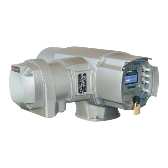
User Manuals: AUMA Aumatic ACExC 01.1 Controls
Manuals and User Guides for AUMA Aumatic ACExC 01.1 Controls. We have
7
AUMA Aumatic ACExC 01.1 Controls manuals available for free PDF download: Manual, Operation Instructions Manual, Short Instructions
AUMA Aumatic ACExC 01.1 Manual (112 pages)
Actuator controls
Brand:
AUMA
| Category:
Control Unit
| Size: 0 MB
Table of Contents
Table of Contents
2
1 Safety Instructions
5
General Notes Regarding Safety
5
Range of Application
6
Warnings and Symbols
6
2 Identification
7
Name Plate
7
Short Description
8
3 Operation
9
Local Operation
9
Operation from REMOTE
9
Menu Navigation Via Push Buttons (for Settings and Indications)
10
Short Overview: Functions of the Push Buttons
10
Structural Design and Navigation
11
Operation and Setting Via AUMA COM-AC Programming Software
12
Operation Setting Via COM-AC
12
Password Change
13
Language Change in the Display
14
LCD Contrast Setting of the Display (Applies Only to Controls with Green Display)
14
4 Indications
15
Status Indications in the Display
15
Status Indication S0/S6 - Operation
15
Status Indication S4 - Torque
16
Torque Indication: Edit
16
Electronic Name Plate
17
Display Indication: Enable View
17
Electronic Name Plate: View
17
Indication Lights/Leds
19
Standard Indication
19
Configuration of the Signals: View/Edit
20
Blinking Behaviour of Indication Lights/Leds: View/Edit
21
5 Signals
22
Signals Via Fieldbus
22
Configuration for Process Representation Input: View
22
Configuration of Adjustable (User-Definable) Signals: View
23
Configuration of Fault Signals: View
25
Percent/Per Mil Coding for Transmission Values: View
26
Feedback Via Output Contacts (Binary) - (Option)
27
Configuration for Output Contacts 1 to 5: View/Edit
27
Configuration for Alarm Contacts (Collective Fault Signal): View/Edit
29
Output Contacts 1 to 5: Use as Running Indication (Blinker)
30
Feedback Signals (Analogue) - (Option)
31
Position Transmitter/Actual Position Source (E2): View
31
Source of the Torque Signal E6: View
32
Feedback Signals (Configuration) Via Analogue Output 1: View
32
Feedback Signals (Configuration) Via Analogue Output 2: View
34
Signal Range at the Analogue Output 2: View/Edit
34
6 Operation Mode
35
Operation Mode off
35
Operation Mode LOCAL
36
Push-To-Run Operation or Self-Retaining: Set for Operation Mode LOCAL
36
Operation Mode REMOTE
37
Push-To-Run Operation or Self-Retaining: Set for Operation Mode REMOTE
37
Operation Mode EMERGENCY
38
Operation Mode (Type of Duty) Activation for an EMERGENCY Operation
38
EMERGENCY Operation: Switch on or Off/Signal Behaviour Definition
39
Actuator Behaviour Definition in Case of an EMERGENCY Operation
39
EMERGENCY Position Definition
40
Motor Protection And/Or Torque Switching: By-Pass
40
Operation Mode FAILURE
41
Failure Behaviour: Switch on or off
41
Source for Initiation (Failure Source): Set for Failure Operation
42
Actuator Reaction (Failure Position): Set on Loss of Signal
42
Preset Position Definition
43
Failure Delay Time Setting
43
Failure Behaviour on Bus Communication Loss
44
7 Functions
45
Type of Seating: Check/Edit End Positions
45
Torque Switching: Check/Set
46
Limit Switching Setting
47
Intermediate Positions (Option)
48
Display Indication: Enable View
48
Intermediate Positions: Switch on or off
49
Intermediate Position Definition
49
Operation Behaviour = Actuator Behaviour Definition
50
Intermediate Positions: Set the Signalling
50
Intermediate Positions with Multiport Valve Function (Option)
52
Check: Multiport Valve Function Availablequestion
52
Check: Positioner Active
53
Display Indication: Enable View
53
Intermediate Positions: Switch on or off
53
Intermediate Position Setting
53
Operation Behaviour = Actuator Behaviour Definition
54
Intermediate Positions Signalling
54
Intermediate Positions in LOCAL: Direct Approach Without Stopping
54
Positioner (Operation Mode SETPOINT MODE)
55
Adaptive Behaviour: Switch on or off
55
Overrun (Inner Dead Band): Set Manually
56
Max. Error Variable (Outer Dead Band): Set Manually
57
Dead Time Setting
57
Closing Fully/Opening Fully (End Position Tolerance for Setpoint E1)
58
Open-Close Duty (REMOTE MODE) and Modulating Duty (SETPOINT MODE) Selection
58
Source of Setpoint E1: View
59
Input Range of Setpoint 1: View/Edit
60
Process Controller (Option)
61
Setting Procedure
62
Process Controller Activation (Check: Process Controller Available?)
62
Proportional Gain Kp Setting
63
Reset Time Ti Setting
63
Rate Time Td Setting
64
Derivative Gain Kd Setting
64
Internal Process Setpoint Setting
65
Behaviour on Loss of the Process Setpoint (Wire Break Monitoring)
66
Inverse Operation Setting
66
Travel Limitation
67
Reaction Monitoring Setting
68
Input Range of Process Setpoint E1: View
69
Input Range of Process Variable E4: View/Edit
69
Stepping Mode (Option)
70
Display Indication: Enable View
70
Stepping Mode: Switch on or off
71
Stepping Range Setting (Start and End of Stepping Mode)
71
ON and off Times Setting
72
Local Controls Enable Function (Option)
73
Selector Switch Functions: Enable/Disable
73
EMERGENCY STOP Function (Option)
75
Description of the Functions
75
Feedback Signals on the Display
76
Feedback Signals Setting Via Output Contacts
76
Feedback Signal Setting Via Leds
76
Profibus DP Interface (Option)
77
Bus Address Setting (Slaveaddress)
77
Redundant Bus Connection with Component Redundancy (Option)
78
Configuration Check for the Second Fieldbus Interface
78
Second Fieldbus Interface Setting
78
Profibus DP-V1 Services (Option)
79
External Inputs for Bus (Option)
80
Signals Assignation for Operation Commands
80
Combination Fieldbus/Standard Interface (Option)
83
Monitoring and Failure Functions
84
Torque Monitoring
84
Motor Protection (Thermal Monitoring)
85
Monitoring of the Max. Number of Starts Per Hour and Max. Running Time Per Hour
86
Operating Time Monitoring
88
Reaction Monitoring
89
Phase Failure Monitoring
90
8 Corrective Action
91
Fault Indications and Warning Indications
91
Status Indication S0 - Faults and Warnings
91
Status Indication S1 - Fault
92
Status Indication S2 - Warnings
92
Status Indication S3 - Causes for Not Ready Remote
94
Diagnostics
95
Operating Data Logging
95
Diagnostic Indications (D) Via the Display
97
Troubleshooting
107
Problems with Position Feedback/Indication E2 (from Actuator)
107
Display Hardly Readable or Illegible
107
Actuator Does Not Run
107
Actuator Does Only Operate from Local
107
Actuator Is Not Switched off by Limit Seating in Direction CLOSE or OPEN
107
Index
108
Parameter Index and Indications on the Display
109
Addresses
110
Advertisement
AUMA Aumatic ACExC 01.1 Manual (96 pages)
Actuator controls
Brand:
AUMA
| Category:
Controller
| Size: 0 MB
Table of Contents
Table of Contents
2
1 Safety Instructions
5
General Notes on Safety
5
Range of Application
6
Warnings and Symbols
6
2 Identification
7
Name Plate
7
Short Description
8
3 Operation
9
Local Operation
9
Operation from REMOTE
9
Menu Navigation Via Push Buttons (for Settings and Indications)
10
Short Overview: Functions of the Push Buttons
10
Structural Design and Navigation
11
Operation and Setting Via AUMA COM-AC Programming Software
12
Operation Setting Via COM-AC
12
Password Change
13
Language Change in the Display
14
LCD Contrast Setting of the Display (Applies Only to Controls with Green Display)
14
4 Indications
15
Status Indications in the Display
15
Status Indication S0/S6 - Operation
15
Status Indication S4 - Torque
16
Torque Indication: Edit
16
Electronic Name Plate
17
Display Indication: Enable View
17
Electronic Name Plate: View
17
Indication Lights/Leds
19
Standard Indication
19
Configuration of the Signals: View/Edit
20
Blinking Behaviour of Indication Lights/Leds: View/Edit
21
5 Signals
22
Signals Via Fieldbus
22
Configuration of Adjustable (User-Definable) Signals
22
Feedback Via Output Contacts (Binary) - (Option)
23
Configuration for Output Contacts 1 to 5: View/Edit
23
Configuration Alarm Contacts (Collective Fault Signal): View/Edit
25
Output Contacts 1 to 5: Use as Running Indication (Blinker)
26
Feedback Signals (Analogue) - (Option)
27
Position Transmitter/Actual Position Source (E2): View
27
Source of the Torque Signal E6: View
28
Feedback Signals (Configuration) Via Analogue Output 1: View
28
Signal Range at the Analogue Output 1: View/Edit
29
Feedback Signals (Configuration) Via Analogue Output 2: View
30
Signal Range at the Analogue Output 2: View/Edit
30
6 Operation Mode
31
Operation Mode off
31
Operation Mode LOCAL
32
Push-To-Run Operation or Self-Retaining: Set for the Operation Mode LOCAL
32
Operation Mode REMOTE
33
Push-To-Run Operation or Self-Retaining: Set for Operation Mode REMOTE
33
Operation Mode EMERGENCY
34
Operation Mode (Type of Duty) Activation for an Emergency Operation
34
EMERGENCY Operation: Switch on or Off/Signal Behaviour Definition
35
Actuator Behaviour Definition in Case of an Emergency Operation
35
EMERGENCY Position Definition
36
Motor Protection And/Or Torque Switching: By-Pass
36
Fault State Behaviour in Case of Bus Communication Loss
37
Failure Behaviour in Case of Analogue Signal Loss (Option)
37
7 Functions
40
Type of Seating: Check/Edit End Positions
40
Torque Switching: Check/Set
41
Limit Switching Setting
42
Intermediate Positions (Option)
43
Display Indication: Enable View
43
Intermediate Positions: Switch on or off
44
Intermediate Position Definition
44
Operation Behaviour = Actuator Behaviour Definition
45
Intermediate Positions: Set the Signalling
45
Intermediate Positions with Multiport Valve Function (Option)
47
Check: Multiport Valve Function Available
47
Check: Positioner Active
48
Display Indication: Enable View
48
Intermediate Positions: Switch on or off
48
Intermediate Position Setting
48
Operation Behaviour = Actuator Behaviour Definition
49
Intermediate Positions Signalling
49
Intermediate Positions in LOCAL: Direct Approach Without Stopping
49
Positioner (Operation Mode SETPOINT MODE)
50
Adaptive Behaviour: Switch on or off
50
Overrun (Inner Dead Band): Set Manually
51
Max. Error Variable (Outer Dead Band): Set Manually
52
Dead Time Setting
52
Closing Fully/Opening Fully (End Position Tolerance for Setpoint E1)
53
Open-Close Duty (REMOTE) or Modulating Duty (SETPOINT) Selection
53
Source of Setpoint E1: View
54
Input Range of Setpoint 1: View/Edit
55
Stepping Mode (Option)
56
Display Indication: Enable View
56
Stepping Mode: Switch on or off
57
Stepping Range Setting (Start and End of Stepping Mode)
57
ON and off Times Setting
58
Local Controls Enable Function (Option)
59
Selector Switch Functions: Enable/Disable
59
EMERGENCY STOP Function (Option)
60
Description of the Functions
60
Feedback Signals on the Display
61
Feedback Signals Setting Via Output Contacts
61
Feedback Signal Setting Via Leds
61
AUMA Aumatic ACExC 01.1 Operation Instructions Manual (88 pages)
Multi-turn actuator
Brand:
AUMA
| Category:
Controller
| Size: 2 MB
Table of Contents
Table of Contents
2
1 Safety Instructions
4
General Notes on Safety
4
Range of Application
5
Warnings and Notes
6
Further References and Symbols
6
2 Identification
7
Name Plate
7
Short Description
9
3 Transport, Storage and Packaging
10
Transport
10
Storage
10
Packaging
10
4 Assembly
11
Handwheel Fitting
11
Multi-Turn Actuator Mounting to Valve/Gearbox
12
Output Drive Types B1, B2, B3, B4, B, and E
12
Output Drive Type a
13
Accessories (Option)
15
Protection Tube for Rising Valve Stem
15
Mounting Positions of the Local Controls
16
5 Electrical Connection
17
General Notes
17
Connecting Via Plug/Socket Connector with Screw-Type Terminals (KP, KPH)
19
Connecting Via Plug/Socket Connector with Spring Cage Terminals (KES)
23
Accessories for Electrical Connection (Option)
26
Controls Mounted to Wall Bracket
26
Parking Frame
27
Protection Cover
27
Ground Connection, External
27
6 Operation
28
Manual Operation
28
Motor Operation
29
Local Operation
29
Operation from REMOTE
29
Menu Navigation Via Push Buttons (for Settings and Indications)
30
Short Overview: Functions of the Push Buttons
30
Structural Design and Navigation
31
Language Change in the Display
32
7 Indications
34
Status Indications in the Display
34
Status Indication S0/S6 - Operation
34
Status Indication S4 - Torque
35
Indication Lights/Leds
36
Mechanical Position Indicator/Running Indication (Option)
36
8 Signals
37
Signals Via Fieldbus
37
Feedback Via Output Contacts (Binary) - (Option)
37
Feedback Signals (Analogue) - (Option)
37
9 Commissioning
38
Type of Seating: Check/Edit for End Positions
39
Torque Switching: Check/Set
42
Limit Switching Setting
45
Bus Address Setting (Slaveaddress)
48
Test Run
51
Rotational Direction Check
51
Limit Switching Check
52
Switch Compartment: Open
53
Mechanical Position Indicator Setting (Option)
53
Gear Stage of the Reduction Gearing: Test/Set
54
Switch Compartment: Close
56
10 Corrective Action
57
Faults During Commissioning
57
Mechanical Position Indicator
57
Fault in End Position (Overrun Not Considered)
57
Push Buttons Do Not React
57
Fault Indications and Warning Indications
58
Status Display S0 - Faults and Warnings
58
Status Indication S1 - Faults
59
Status Indication S2 - Warnings
60
Status Indication S3 - Causes for Not Ready Remote
62
Fuses
63
Fuses Within the Actuator Controls
63
Motor Protection (Thermal Monitoring)
64
11 Servicing and Maintenance
65
Preventive Measures for Servicing and Safe Operation
65
Disconnection from the Mains
66
Maintenance
67
Disposal and Recycling
68
12 Spare Parts List
70
Multi-Turn Actuator Saexc 07.1 - Saexc 16.1/Sarexc 07.1 - Sarexc
70
Controls Acexc 01.1 with Ex-Plug/Socket Connector with Terminal Board (KP, KPH)
72
Controls Acexc 01.1 with Ex-Plug-In Terminal Connection (KES)
74
13 Technical Data
76
14 Certificates
81
Declaration of Conformity and Declaration of Incorporation
81
PTB Certificate
82
Index
85
Addresses
86
Advertisement
AUMA Aumatic ACExC 01.1 Operation Instructions Manual (68 pages)
Actuator controls.
Brand:
AUMA
| Category:
Controller
| Size: 0 MB
Table of Contents
Table of Contents
2
1 Safety Instructions
4
Range of Application
4
Commissioning (Electrical Connection)
4
Maintenance
4
Warnings and Notes
4
2 Short Description
4
3 Transport and Storage
5
4 General Information about Devicenet
5
Devicenet Cable
6
Devicenet Topology
6
Devicenet Communication
7
Devicenet Object Model
7
Protection Functions
8
5 Technical Data
9
6 AUMATIC Devicenet Design
13
7 Electrical Connection
14
Power Supply (Standard)
14
Remote Position Transmitter
14
AUMATIC on Wall Bracket
14
Fitting of the Connection Housing
15
Test Run
15
Check Limit and Torque Switching
15
Bus Connection (Standard)
15
Mains and Bus Connection for Explosion-Proof Version
17
Bus Cables
19
Setting the Devicenet Address and the Baud Rate Via the Local Controls
20
Further Parameters of the Devicenet Interface
23
8 Commissioning with Controls Introduction
24
Functions of the AUMATIC with Devicenet
24
Setting of the Devicenet Interface of the AUMATIC
24
Communication Model
24
Object Model of the AUMATIC
24
List of Objects Available in the AUMATIC
25
Bus Access
25
Explicit Messages
25
Poll I/O Connection
25
Configuration of the Poll I/O Connection Via the Local Controls
25
Configuration of the Poll I/O Connection Via the Devicenet Configuration Tool
25
9 Poll I/O Data Interface of the AUMATIC
26
Description of the Input Data
26
Detailed Description of the Input Data
31
Description of the Output Data
33
Detailed Description of the Output Data
34
10 Operation Parameters of the Actuator
35
11 Description of Actuator Functions
39
Operation Commands for OPEN / CLOSE Operation
39
Positioner
40
Stepping Mode
40
12 Safety Function
40
13 Release Function of the Local Controls (Option)
41
14 Additional Control Inputs (Option)
42
15 Combination Fieldbus / Standard Interface (Option)
44
16 EMERGENCY STOP Function (Option)
45
17 Redundant Bus Connection with Component Redundancy (Option)
47
Settings for the Redundant Devicenet Interface 2 (Component Redundancy)
47
External Change-Over of the Communication Channels
48
Details of the Change-Over
48
18 Indication and Programming of the AUMATIC
49
Software Parameters of the Devicenet Interface
49
Menu Indications
49
19 Description Via Devicenet Interface
52
Assignment of the Customer Inputs of the Devicenet Interface (Option)
53
Devicenet Connection Assignment
53
20 Trouble Shooting and Corrective Actions
54
Optical Signals During Operation
54
Status Indications in the Display
55
Devicenet Diagnosis Indication in the Display
55
Offline Connection Set of the AUMATIC
56
Reset of the AUMATIC to the Factory Settings
56
Actuator Can Not be Controlled Via Devicenet
57
21 Appendix A EDS File
59
22 Appendix B Standard Wiring Diagram
60
Legend to Standard Wiring Diagram
61
23 Appendix C Proposed Wiring Diagrams
62
24 Appendix D Literature References
65
25 Appendix E Connection of the Screen for AUMATIC Acexc
65
Index
67
Addresses of AUMA Offices and Representatives
68
AUMA Aumatic ACExC 01.1 Manual (48 pages)
Actuator controls
Brand:
AUMA
| Category:
Controller
| Size: 0 MB
Table of Contents
Table of Contents
2
Process Representation Input Arrangement
2
Process Representation Input Arrangement
3
1 Safety Instructions
4
General Notes Regarding Safety
4
Range of Application
5
Warnings and Symbols
5
2 General Information about Profibus DP
6
Basic Characteristics
6
Basic Functions of Profibus DP
7
Transfer Mode
7
Bus Access
7
Communication
7
Functionality
7
Protection Functions
7
Device Types
7
3 Commissioning
8
Introduction
8
Parameter Setting
8
Configuring the Profibus DP Interface of the AUMATIC
8
Communication Start-Up
9
AUMA User Parameters (AUMA Specific Parameters)
10
Process Representation Input (User Parameter 1)
10
Settable (User Definable) Signals (User Parameters 2 to 8 and 11 to 34)
10
Alarm Contacts/Collective Fault Signal (User Parameter 9)
12
Percent/Per Mil Coding for Transmission Values (User Parameter 10)
13
Profibus DP-V1 Services (Option)
14
4 Description of the Data Interface
15
Input Data (Process Representation Input) - Signals
15
Process Representation Input Arrangement 1 (Default Process Representation)
15
Process Representation Input Arrangement
18
Signal Description Within Process Representation Input Arrangement 1 (Default Process Representation)
19
Output Data (Process Representation Output)
28
4.2.1 Description of the Output Data
28
5 Description of the Profibus DP Board
33
Displays (Optical Signals)
33
Connections
34
5.2.1 Profibus DP Bus Connection
34
Customer Inputs (Option)
34
Redundant Bus Connection with Component Redundancy (Option)
35
6 Corrective Actions
36
Fault Indications and Warning Indications
36
Diagnostics
36
Troubleshooting
36
6.3.1 Measuring the Profibus Signals Using an Oscilloscope
39
7 Technical Data
40
8 Appendix - Proposed External Wiring Diagram
41
Connecting External Sensors, 2-Wire Technology
41
Connecting External Sensors, 3-Wire Technology
42
Connecting External Sensors, 4-Wire Technology
43
Index
45
Addresses
46
AUMA Aumatic ACExC 01.1 Operation Instructions Manual (20 pages)
Actuator controls
Brand:
AUMA
| Category:
Control Unit
| Size: 1 MB
Table of Contents
Table of Contents
2
Process Representation Input Arrangement
2
Process Representation Input Arrangement
3
Safety Instructions
4
Range of Application
4
Commissioning (Electrical Connection)
4
Maintenance
4
Warnings and Notes
4
Short Description
4
Process Representation Input Arrangement
4
Transport and Storage
5
General Information about Profibus DP
5
Basic Characteristics
5
Basic Functions of Profibus DP
6
Transfer Mode
6
Bus Access
6
Communication
6
Functionality
6
Protection Functions
6
Device Types
6
Technical Data
7
Design AUMATIC Profibus DP
11
Electrical Connection
12
Power Supply (Standard)
12
Remote Position Transmitter
12
AUMATIC on Wall Bracket
12
Fitting of the Connection Housing
13
Test Run
13
Bus Connection (Standard)
13
Mains and Bus Connection for Explosion-Proof Version
15
Bus Cables
17
Setting the Profibus DP Address Via Local Controls
18
Commissioning with Controls
20
Introduction
20
Programming
20
Configuration of the Profibus DP Interface of the AUMATIC
20
AUMA Aumatic ACExC 01.1 Short Instructions (16 pages)
Actuator controls, Profibus DP
Brand:
AUMA
| Category:
Control Unit
| Size: 0 MB
Table of Contents
Table of Contents
2
1 Safety Instructions
3
Range of Application
3
Commissioning (Electrical Connection)
3
Maintenance
3
Warnings and Notes
3
2 Short Description
3
3 Electrical Connection
4
Power Supply (Standard)
4
Remote Position Transmitter
4
AUMATIC on Wall Bracket
4
Fitting of the Connection Housing
5
Test Run
5
Bus Connection (Standard)
5
Mains and Bus Connection for Explosion-Proof Version
7
Bus Cables
9
Setting the Profibus DP Address Via Local Controls
10
4 Redundant Bus Connection with Component Redundancy (Option)
12
Settings for the Redundant Profibus Interface 2 (Component Redundancy)
12
5 Description Profibus DP Interface
13
Status Indications in the Display
13
Assignment of the Customer Inputs of the Profibus DP Interface (Option)
14
Assignment of the Profibus DP Connection
14
6 Appendix A Connection of the Screen for AUMATIC Acexc
15
Advertisement
Related Products
AUMA ACExC 01.2 KT/KM
AUMA AUMATIC AC 01.2
AUMA Aumatic AC 01.1
AUMA ACV 01.2 01.2
AUMA AC 01.2 Profinet
AUMA ACT 01.2
AUMA AC 01.2-SIL
AUMA AC 01.2-22X
AUMA AC 01.2-22Y
AUMA AC 01.2 01.2
AUMA Categories
Controller
Industrial Equipment
Control Unit
Control Systems
Valve Positioners
More AUMA Manuals
Login
Sign In
OR
Sign in with Facebook
Sign in with Google
Upload manual
Upload from disk
Upload from URL