AUMA SA Series Operating Instructions Manual
Multi-turn actuators
Hide thumbs
Also See for SA Series:
- Operation instructions manual (100 pages) ,
- Manual (52 pages) ,
- Operation instructions manual (48 pages)
Table of Contents
Advertisement
Advertisement
Table of Contents

Related Manuals for AUMA SA Series


Summary of Contents for AUMA SA Series
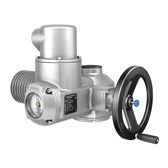
- Page 1 Multi-turn actuators SA 07.2 SA 16.2 SAR 07.2 SAR 16.2 Control unit: electronic (MWG) with actuator controls AC 01.2 Non-Intrusive Control Parallel Profibus DP Profinet Modbus RTU Modbus TCP/IP EtherNet/IP Foundation Fieldbus HART Operation instructions Assembly and commissioning...
-
Page 2: Table Of Contents
SA 07.2 SA 16.2 / SAR 07.2 SAR 16.2 Control unit: electronic (MWG) Table of contents AC 01.2 Non-Intrusive EtherNet/IP Read operation instructions first. Observe safety instructions. These operation instructions are part of the product. Store operation instructions during product life. Pass on instructions to any subsequent user or owner of the product. - Page 3 SA 07.2 SA 16.2 / SAR 07.2 SAR 16.2 Control unit: electronic (MWG) AC 01.2 Non-Intrusive EtherNet/IP Table of contents 5.3.3. Terminal compartment (for mains connection): close 5.3.4. Fieldbus terminal compartment: open 5.3.5. Industrial Ethernet cable: connect 5.3.6. Fieldbus terminal compartment: close 5.4.
- Page 4 SA 07.2 SA 16.2 / SAR 07.2 SAR 16.2 Control unit: electronic (MWG) Table of contents AC 01.2 Non-Intrusive EtherNet/IP 9.6.2. Direction of rotation at hollow shaft/stem: check 9.6.3. Limit switching: check Commissioning (settings/options in the actuator)............. 10.1. Switch compartment: open/close 10.2.
-
Page 5: Safety Instructions
SA 07.2 SA 16.2 / SAR 07.2 SAR 16.2 Control unit: electronic (MWG) AC 01.2 Non-Intrusive EtherNet/IP Safety instructions Safety instructions 1.1. Prerequisites for the safe handling of the product The end user or the contractor must ensure that all legal requirements, directives, Standards/directives guidelines, national regulations and recommendations with respect to assembly, electrical connection, commissioning and operation are met at the place of installation. -
Page 6: Applications In Ex Zone 22 (Option)
SA 07.2 SA 16.2 / SAR 07.2 SAR 16.2 Control unit: electronic (MWG) Safety instructions AC 01.2 Non-Intrusive EtherNet/IP Service lifts according to EN 81-1/A1 Escalators Continuous duty Buried service Continuous submersion (observe enclosure protection) Potentially explosive areas, with the exception of zone 22 Radiation exposed areas in nuclear power plants No liability can be assumed for inappropriate or unintended use. -
Page 7: Warnings And Notes
SA 07.2 SA 16.2 / SAR 07.2 SAR 16.2 Control unit: electronic (MWG) AC 01.2 Non-Intrusive EtherNet/IP Safety instructions 1.4. Warnings and notes The following warnings draw special attention to safety-relevant procedures in these operation instructions, each marked by the appropriate signal word (DANGER, WARNING, CAUTION, NOTICE). -
Page 8: Identification
SA 07.2 SA 16.2 / SAR 07.2 SAR 16.2 Control unit: electronic (MWG) Identification AC 01.2 Non-Intrusive EtherNet/IP Identification 2.1. Name plate Figure 1: Arrangement of name plates Actuator name plate Actuator controls name plate Motor name plate Additional plate, e.g. KKS plate (Power Plant Classification System) Actuator name plate Figure 2: Actuator name plate (example) (= manufacturer logo);... - Page 9 SA 07.2 SA 16.2 / SAR 07.2 SAR 16.2 Control unit: electronic (MWG) AC 01.2 Non-Intrusive EtherNet/IP Identification Actuator controls name plate Figure 3: Name plate for actuator controls (example) Type designation Order number Serial number Actuator terminal plan Actuator controls terminal plan Mains voltage AUMA power class for switchgear Permissible ambient temperature...
- Page 10 SA 07.2 SA 16.2 / SAR 07.2 SAR 16.2 Control unit: electronic (MWG) Identification AC 01.2 Non-Intrusive EtherNet/IP Descriptions referring to name plate indications Type designation Figure 5: Type designation (example) Type and size of actuator Flange size Type and size These instructions apply to the following devices types and sizes: SA..= Type = Multi-turn actuator for open-close duty Sizes and generation: 07.2, 07.6, 10.2, 14.2, 14.6, 16.2...
-
Page 11: Short Description
SA 07.2 SA 16.2 / SAR 07.2 SAR 16.2 Control unit: electronic (MWG) AC 01.2 Non-Intrusive EtherNet/IP Identification Figure 6: Link to AUMA Assistant App: For further Service & Support, software/apps/... refer to www.auma.com. 2.2. Short description AUMA multi-turn actuators SA 07.2 SA 16.2/SAR 07.2 SAR 16.2 are driven by an electric motor and are capable of withstanding thrust in combination with output... -
Page 12: Transport And Storage
SA 07.2 SA 16.2 / SAR 07.2 SAR 16.2 Control unit: electronic (MWG) Transport and storage AC 01.2 Non-Intrusive EtherNet/IP Transport and storage 3.1. Transport For transport to place of installation, use sturdy packaging. Actuator and actuator controls Hovering load! Death or serious injury. - Page 13 SA 07.2 SA 16.2 / SAR 07.2 SAR 16.2 Control unit: electronic (MWG) AC 01.2 Non-Intrusive EtherNet/IP Transport and storage Table 5: Weights for multi-turn actuators SA 07.2 SA 16.2 / SAR 07.2 SAR 16.2 with 3-phase AC motors Type designation Motor type Weight Actuator...
-
Page 14: Storage
SA 07.2 SA 16.2 / SAR 07.2 SAR 16.2 Control unit: electronic (MWG) Transport and storage AC 01.2 Non-Intrusive EtherNet/IP Table 7: Weights for multi-turn actuators SA 07.2 SA 16.2 / SAR 07.2 SAR 16.2 With DC motors Type designation Motor type Weight Actuator... - Page 15 SA 07.2 SA 16.2 / SAR 07.2 SAR 16.2 Control unit: electronic (MWG) AC 01.2 Non-Intrusive EtherNet/IP Transport and storage Risk of damage due to excessively low temperatures! Actuator controls may only be stored permanently down to 30 °C. On request, actuators controls may be transported in specific cases and for short duration at temperatures down to 60 °C.
-
Page 16: Assembly
SA 07.2 SA 16.2 / SAR 07.2 SAR 16.2 Control unit: electronic (MWG) Assembly AC 01.2 Non-Intrusive EtherNet/IP Assembly 4.1. Mounting position When using grease as lubricant, the product described herein can be operated in any mounting position. When using oil instead of grease within the actuator gear housing, perpendicular mounting position is specified whereby the flange is pointing downward. -
Page 17: Handwheel Fitting
SA 07.2 SA 16.2 / SAR 07.2 SAR 16.2 Control unit: electronic (MWG) AC 01.2 Non-Intrusive EtherNet/IP Assembly Figure 9: Output drive type B Flange multi-turn actuator (e.g. F07) Hollow shaft Output drive sleeve (illustration examples) [3] B/B1/B2 and [3]* B3/B4/E, respectively with bore and keyway Gearbox/valve shaft with parallel key Spigot at valve flanges should be loose fit. -
Page 18: Multi-Turn Actuator: Mount To Valve/Gearbox
SA 07.2 SA 16.2 / SAR 07.2 SAR 16.2 Control unit: electronic (MWG) Assembly AC 01.2 Non-Intrusive EtherNet/IP Slip handwheel [3] onto input shaft. Secure handwheel [3] with retaining ring [4]. Information: The retaining ring [4] (together with these operation instructions) is stored in a weatherproof bag, which is attached to the device prior to delivery. -
Page 19: Multi-Turn Actuator With Output Drive Type A: Mount
SA 07.2 SA 16.2 / SAR 07.2 SAR 16.2 Control unit: electronic (MWG) AC 01.2 Non-Intrusive EtherNet/IP Assembly Re-insert stem nut [1] with axial needle roller bearings [2] into output drive. Screw in spigot ring [3] until it is firm against the shoulder. 4.4.2. -
Page 20: Multi-Turn Actuator With Output Drive Type B: Mount
SA 07.2 SA 16.2 / SAR 07.2 SAR 16.2 Control unit: electronic (MWG) Assembly AC 01.2 Non-Intrusive EtherNet/IP 11. Tighten fastening screws [5] between valve and output drive type A crosswise applying a torque according to table. 4.4.3. Multi-turn actuator with output drive type B: mount Figure 13: Mounting output drive types B Multi-turn actuator Valve/gearbox... -
Page 21: Accessories For Assembly
SA 07.2 SA 16.2 / SAR 07.2 SAR 16.2 Control unit: electronic (MWG) AC 01.2 Non-Intrusive EtherNet/IP Assembly 4.5. Accessories for assembly 4.5.1. Stem protection tube for rising valve stem Figure 14: Assembly of the stem protection tube Protective cap for stem protection tube (fitted) [1]* Option: Protective cap made of steel (screwed) Stem protection tube... -
Page 22: Mounting Positions Of Local Controls
SA 07.2 SA 16.2 / SAR 07.2 SAR 16.2 Control unit: electronic (MWG) Assembly AC 01.2 Non-Intrusive EtherNet/IP 4.6. Mounting positions of local controls Figure 16: Mounting positions The mounting position of the local controls is implemented according to the order. If, after mounting the actuator to the valve or the gearbox on site, the local controls are in an unfavourable position, the mounting position can be changed at a later date. -
Page 23: Electrical Connection
SA 07.2 SA 16.2 / SAR 07.2 SAR 16.2 Control unit: electronic (MWG) AC 01.2 Non-Intrusive EtherNet/IP Electrical connection Electrical connection 5.1. Basic information Electric shock due to presence of hazardous voltage! Failure to observe this warning can result in death, serious injury, or property damage. The electrical connection must be carried out exclusively by suitably qualified personnel. - Page 24 SA 07.2 SA 16.2 / SAR 07.2 SAR 16.2 Control unit: electronic (MWG) Electrical connection AC 01.2 Non-Intrusive EtherNet/IP Table 13: Current consumption of actuator controls Mains voltage Max. current consumption Permissible variation of the mains voltage ±10 % ±30 % 100 to 120 V AC 750 mA 1,000 mA...
-
Page 25: Overview Of Auma Electrical Connections
SA 07.2 SA 16.2 / SAR 07.2 SAR 16.2 Control unit: electronic (MWG) AC 01.2 Non-Intrusive EtherNet/IP Electrical connection Network cables are sensitive to interference. Motor cables are interference sources. Cable installation in ac- cordance with EMC Lay cables being susceptible to interference or sources of interference at the highest possible distance from each other. -
Page 26: Sj Electrical Connection (Auma Plug/Socket Connector)
SA 07.2 SA 16.2 / SAR 07.2 SAR 16.2 Control unit: electronic (MWG) Electrical connection AC 01.2 Non-Intrusive EtherNet/IP 5.3. SJ electrical connection (AUMA plug/socket connector) Figure 18: SJ electrical connection Terminal compartment (in cover) [1A] Cable entries for mains connection (power and control contacts) [1B] Cable entries for fieldbus cables Socket carrier with screw-type terminals... -
Page 27: Terminal Compartment (For Mains Connection): Open
SA 07.2 SA 16.2 / SAR 07.2 SAR 16.2 Control unit: electronic (MWG) AC 01.2 Non-Intrusive EtherNet/IP Electrical connection 5.3.1. Terminal compartment (for mains connection): open Figure 19: Open mains terminal compartment Connection housing Screws for frame O-ring Screws for socket carrier Socket carrier Cable entries for mains connection (power and control contacts) Blanking plug... -
Page 28: Cable Connection
SA 07.2 SA 16.2 / SAR 07.2 SAR 16.2 Control unit: electronic (MWG) Electrical connection AC 01.2 Non-Intrusive EtherNet/IP 5.3.2. Cable connection Table 20: Terminal cross sections and terminal tightening torques Designation Terminal cross sections Tightening torques Power contacts 6 mm (flexible) 1.5 Nm (U1, V1, W1, U2, V2, W2) -
Page 29: Terminal Compartment (For Mains Connection): Close
SA 07.2 SA 16.2 / SAR 07.2 SAR 16.2 Control unit: electronic (MWG) AC 01.2 Non-Intrusive EtherNet/IP Electrical connection 5.3.3. Terminal compartment (for mains connection): close Figure 22: Close mains terminal compartment Connection housing Screws for frame O-ring Screws for socket carrier Socket carrier Cable gland (not included in delivery) Blanking plug... -
Page 30: Fieldbus Terminal Compartment: Open
SA 07.2 SA 16.2 / SAR 07.2 SAR 16.2 Control unit: electronic (MWG) Electrical connection AC 01.2 Non-Intrusive EtherNet/IP 5.3.4. Fieldbus terminal compartment: open Figure 23: Open cover to fieldbus terminal compartment Cover (fieldbus terminal compartment) Screws for cover O-ring Cable entries for fieldbus cables Blanking plug For connecting the Industrial Ethernet cable within the AUMA plug/socket connector,... -
Page 31: Fieldbus Terminal Compartment: Close
SA 07.2 SA 16.2 / SAR 07.2 SAR 16.2 Control unit: electronic (MWG) AC 01.2 Non-Intrusive EtherNet/IP Electrical connection Figure 25: EtherNet/IP module RJ-45 plug-in socket for connecting the Industrial Ethernet cable Power supply For connecting cables to RJ-45 connectors, proceed in compliance with the Cable connection connector manufacturer specifications. -
Page 32: Compact Version Sf Electrical Connection For Ethernet/Ip
SA 07.2 SA 16.2 / SAR 07.2 SAR 16.2 Control unit: electronic (MWG) Electrical connection AC 01.2 Non-Intrusive EtherNet/IP 5.4. Compact version SF electrical connection for EtherNet/IP Figure 27: SF electrical connection Terminal compartment (with cover) [1A] Cable entries for mains connection (pins for motors and pins for controls) [1B] Cable entries for network cables Socket carrier with screw-type terminals... -
Page 33: Terminal Compartment (For Mains Connection): Open
SA 07.2 SA 16.2 / SAR 07.2 SAR 16.2 Control unit: electronic (MWG) AC 01.2 Non-Intrusive EtherNet/IP Electrical connection 5.4.1. Terminal compartment (for mains connection): open Figure 28: Open mains terminal compartment Connection housing Screws for frame O-ring Screws for socket carrier Socket carrier Cable entries for mains connection (pins for motors and pins for controls) Blanking plug... -
Page 34: Cable Connection
SA 07.2 SA 16.2 / SAR 07.2 SAR 16.2 Control unit: electronic (MWG) Electrical connection AC 01.2 Non-Intrusive EtherNet/IP 5.4.2. Cable connection Table 22: Terminal cross sections and terminal tightening torques Designation Terminal cross sections Tightening torques Power contacts 6 mm (flexible) 1.5 Nm (U1, V1, W1, U2, V2, W2) -
Page 35: Terminal Compartment (For Mains Connection): Close
SA 07.2 SA 16.2 / SAR 07.2 SAR 16.2 Control unit: electronic (MWG) AC 01.2 Non-Intrusive EtherNet/IP Electrical connection 5.4.3. Terminal compartment (for mains connection): close Figure 31: Close mains terminal compartment Connection housing Screws for connection housing O-ring Screws for socket carrier Socket carrier Cable gland (not included in scope of delivery) Blanking plug... -
Page 36: Industrial Ethernet Cable: Connect
SA 07.2 SA 16.2 / SAR 07.2 SAR 16.2 Control unit: electronic (MWG) Electrical connection AC 01.2 Non-Intrusive EtherNet/IP 5.4.4. Industrial Ethernet cable: connect M12 connector for connecting the Industrial Ethernet cable M12 port Remove protective cap. Cable connection Connect M12 connector [1] to M12 port for Ethernet cable [2]. Tighten cap nut. -
Page 37: Parking Frame
SA 07.2 SA 16.2 / SAR 07.2 SAR 16.2 Control unit: electronic (MWG) AC 01.2 Non-Intrusive EtherNet/IP Electrical connection The wall bracket allows separate mounting of actuator controls and actuator. Application If the actuator cannot be accessed safely. If the actuator is subjected to high temperatures. In case of heavy vibration of the valve. -
Page 38: External Earth Connection
SA 07.2 SA 16.2 / SAR 07.2 SAR 16.2 Control unit: electronic (MWG) Electrical connection AC 01.2 Non-Intrusive EtherNet/IP 5.5.3. External earth connection Figure 34: Earth connection for multi-turn actuator External earth connection (U-bracket) for connection to equipotential compensation. Application Table 23: Terminal cross sections and earth connection tightening torques Conductor type... -
Page 39: Operation
SA 07.2 SA 16.2 / SAR 07.2 SAR 16.2 Control unit: electronic (MWG) AC 01.2 Non-Intrusive EtherNet/IP Operation Operation 6.1. Manual operation The handwheel allows actuator operation even in case of power failure. However, handwheel operation is only provided for occasional manual valve operation. Manual operation is automatically disengaged when motor is started again. -
Page 40: Motor Operation
SA 07.2 SA 16.2 / SAR 07.2 SAR 16.2 Control unit: electronic (MWG) Operation AC 01.2 Non-Intrusive EtherNet/IP Figure 36: Handwheel without/with overload protection Handwheel without overload protection (standard) Handwheel with overload protection/safety hub (option) 6.2. Motor operation Perform all commissioning settings and the test run prior to motor operation. Valve damage due to incorrect basic setting! Prior to electrical operation of the actuator, the basic settings i.e. -
Page 41: Actuator Operation From Remote
SA 07.2 SA 16.2 / SAR 07.2 SAR 16.2 Control unit: electronic (MWG) AC 01.2 Non-Intrusive EtherNet/IP Operation Hot surfaces, e.g. possibly caused by high ambient temperatures or strong direct sunlight! Danger of burns Verify surface temperature and wear protective gloves. Set selector switch [5] to position Local control (LOCAL). -
Page 42: Menu Layout And Navigation
SA 07.2 SA 16.2 / SAR 07.2 SAR 16.2 Control unit: electronic (MWG) Operation AC 01.2 Non-Intrusive EtherNet/IP Figure 38: [1 4] Push buttons or navigation support Selector switch Display Table 25: Important push button functions for menu navigation Push buttons Navigation sup- Functions port on display... -
Page 43: User Level, Password
SA 07.2 SA 16.2 / SAR 07.2 SAR 16.2 Control unit: electronic (MWG) AC 01.2 Non-Intrusive EtherNet/IP Operation Figure 40: Marking with ID ID starts with = status menu ID starts with = main menu It is possible to select between status menu S and main menu M: Group selection For this, set selector switch to 0 (OFF), hold down push button C for approx. -
Page 44: Password Entry
SA 07.2 SA 16.2 / SAR 07.2 SAR 16.2 Control unit: electronic (MWG) Operation AC 01.2 Non-Intrusive EtherNet/IP Table 26: User levels and authorisations Designation (user level) Authorisation/password Observer (1) Verify settings No password required Operator (2) Change settings Default factory password: 0000 Maintenance (3) Reserved for future extensions Specialist (4) -
Page 45: Language In The Display
SA 07.2 SA 16.2 / SAR 07.2 SAR 16.2 Control unit: electronic (MWG) AC 01.2 Non-Intrusive EtherNet/IP Operation Select parameter Change passwords either: Change passwords click via the menu to parameter, or via direct display: press and enter ID M0229 Display indicates: ▶... - Page 46 SA 07.2 SA 16.2 / SAR 07.2 SAR 16.2 Control unit: electronic (MWG) Operation AC 01.2 Non-Intrusive EtherNet/IP Enter password (→ enter password). Display indicates: ▶ Language and Save (bottom row) Language selection 10. Select new language via Up ▲ Down ▼ resulting in the following significations: black triangle: ▶...
-
Page 47: Indications
SA 07.2 SA 16.2 / SAR 07.2 SAR 16.2 Control unit: electronic (MWG) AC 01.2 Non-Intrusive EtherNet/IP Indications Indications 7.1. Indications during commissioning When switching on the power supply, all LEDs on the local controls illuminate for LED test approx. 1 second. This optical feedback indicates that the voltage supply is connected to the controls and all LEDs are operable. -
Page 48: Feedback Indications From Actuator And Valve
SA 07.2 SA 16.2 / SAR 07.2 SAR 16.2 Control unit: electronic (MWG) Indications AC 01.2 Non-Intrusive EtherNet/IP Figure 48: Information in the status bar (top) Operation mode Error symbol (only for faults and warnings) ID number: S = Status page If further details or information are available with reference to the display, the following Navigation support indications Details or More appear in the navigation support (bottom display row). - Page 49 SA 07.2 SA 16.2 / SAR 07.2 SAR 16.2 Control unit: electronic (MWG) AC 01.2 Non-Intrusive EtherNet/IP Indications Figure 52: Torque allows to select the unit displayed (percent %, Newton metre Nm Select unit The push button or "foot-pound" ft-lb Figure 53: Units of torque 100 % indication equals the max.
-
Page 50: Status Indications According To Auma Classification
SA 07.2 SA 16.2 / SAR 07.2 SAR 16.2 Control unit: electronic (MWG) Indications AC 01.2 Non-Intrusive EtherNet/IP Figure 55: Indication for setpoint control (positioner) Position setpoint Actual position value The pivot points and their operation behaviour (operation profile) are shown on the Pivot point axis pivot point axis by means of symbols. -
Page 51: Status Indications According To Namur Recommendation
SA 07.2 SA 16.2 / SAR 07.2 SAR 16.2 Control unit: electronic (MWG) AC 01.2 Non-Intrusive EtherNet/IP Indications Not ready REMOTE (S0006) The S0006 display shows indications of the Not ready REMOTE group. If such an indication has occurred, the display shows S0006: the number of indications occurred a blinking crossbar after approx. - Page 52 SA 07.2 SA 16.2 / SAR 07.2 SAR 16.2 Control unit: electronic (MWG) Indications AC 01.2 Non-Intrusive EtherNet/IP Figure 61: Function check For further information, please also refer to <Corrective action>. Maintenance required (S0010) The S0010 indication shows maintenance indications according to NAMUR recommendation NE 107.
-
Page 53: Indication Lights Of Local Controls
SA 07.2 SA 16.2 / SAR 07.2 SAR 16.2 Control unit: electronic (MWG) AC 01.2 Non-Intrusive EtherNet/IP Indications 7.3. Indication lights of local controls Figure 64: Arrangement and signification of indication lights Marking with symbols (standard) Marking with figures 1 6 (option) End position CLOSED reached (blinking: operation in direction CLOSE) 2 Tc Torque fault CLOSE... -
Page 54: Optional Indications
SA 07.2 SA 16.2 / SAR 07.2 SAR 16.2 Control unit: electronic (MWG) Indications AC 01.2 Non-Intrusive EtherNet/IP 7.4. Optional indications 7.4.1. Mechanical position indication (self-adjusting) Figure 65: Mechanical position indicator End position OPEN reached End position CLOSED reached Independent of power supply Characteristics Used as running indication: Indicator disc (with arrow ) rotates during actu-... -
Page 55: Signals (Output Signals)
SA 07.2 SA 16.2 / SAR 07.2 SAR 16.2 Control unit: electronic (MWG) AC 01.2 Non-Intrusive EtherNet/IP Signals (output signals) Signals (output signals) 8.1. Status signals via output contacts (digital outputs) Output contacts are only available if a parallel interface is provided in addition to the Conditions communication interface. -
Page 56: Commissioning (Basic Settings)
SA 07.2 SA 16.2 / SAR 07.2 SAR 16.2 Control unit: electronic (MWG) Commissioning (basic settings) AC 01.2 Non-Intrusive EtherNet/IP Commissioning (basic settings) Set selector switch to position 0 (OFF). Information: The selector switch is not a mains switch. When positioned to 0 (OFF), the actuator cannot be operated. -
Page 57: Torque Switching: Set
SA 07.2 SA 16.2 / SAR 07.2 SAR 16.2 Control unit: electronic (MWG) AC 01.2 Non-Intrusive EtherNet/IP Commissioning (basic settings) Up ▲ Down ▼ to select user: User login Information: Required user level: Specialist (4) or higher The symbols have the following meaning: black triangle: ▶... -
Page 58: Limit Switching: Set
SA 07.2 SA 16.2 / SAR 07.2 SAR 16.2 Control unit: electronic (MWG) Commissioning (basic settings) AC 01.2 Non-Intrusive EtherNet/IP Press Ok. Display shows the set value. The bottom row indicates: Edit Esc Press Edit. Display indicates: Specialist (4) → continue with step 7 in bottom row Up ▲... - Page 59 SA 07.2 SA 16.2 / SAR 07.2 SAR 16.2 Control unit: electronic (MWG) AC 01.2 Non-Intrusive EtherNet/IP Commissioning (basic settings) Limit switching M0010 Set end pos.CLOSED? M0084 Set end pos. OPEN? M0085 Set selector switch to position 0 (OFF). Select main menu Press push button C and hold it down for approx.
-
Page 60: Connection Between Ethernet/Ip Module And Computer: Check
SA 07.2 SA 16.2 / SAR 07.2 SAR 16.2 Control unit: electronic (MWG) Commissioning (basic settings) AC 01.2 Non-Intrusive EtherNet/IP 10. Press Yes to confirm new end position. Confirm new end posi- tion Display indicates: End pos. CLOSED set! The left LED is illuminated (standard version) and thus indicates that the end position CLOSED setting is complete. -
Page 61: Ethernet/Ip Module Configuration
SA 07.2 SA 16.2 / SAR 07.2 SAR 16.2 Control unit: electronic (MWG) AC 01.2 Non-Intrusive EtherNet/IP Commissioning (basic settings) Start the Windows Desktop App “command prompt” at computer and enter the ping 192.168.255.1 command. If responses are sent: Connection between module and computer is If no responses are sent: Check whether module and computer are connected to the same subnet. - Page 62 SA 07.2 SA 16.2 / SAR 07.2 SAR 16.2 Control unit: electronic (MWG) Commissioning (basic settings) AC 01.2 Non-Intrusive EtherNet/IP Select the interface card in the next window and confirm with Select. Now, the software searches for the EtherNet/IP module. Should the scan fail, either the Windows firewall or the antivirus software might have Information to be deactivated.
-
Page 63: Test Run
SA 07.2 SA 16.2 / SAR 07.2 SAR 16.2 Control unit: electronic (MWG) AC 01.2 Non-Intrusive EtherNet/IP Commissioning (basic settings) Confirm reboot with OK. The process is started. After rebooting, the settings are saved and active. 9.6. Test run Only perform test run only once all settings previously described have been performed. - Page 64 SA 07.2 SA 16.2 / SAR 07.2 SAR 16.2 Control unit: electronic (MWG) Commissioning (basic settings) AC 01.2 Non-Intrusive EtherNet/IP Switch on actuator in direction CLOSE and observe the direction of rotation on the mechanical position indication: For self-adjusting mechanical position indication: The direction of rotation is correct if the actuator operates in direction CLOSE and arrow turns clockwise in direction CLOSE (symbol...
-
Page 65: Direction Of Rotation At Hollow Shaft/Stem: Check
SA 07.2 SA 16.2 / SAR 07.2 SAR 16.2 Control unit: electronic (MWG) AC 01.2 Non-Intrusive EtherNet/IP Commissioning (basic settings) 9.6.2. Direction of rotation at hollow shaft/stem: check Figure 69: Direction of rotation of the hollow shaft/stem for operation in direction CLOSE (“clockwise closing”... - Page 66 SA 07.2 SA 16.2 / SAR 07.2 SAR 16.2 Control unit: electronic (MWG) Commissioning (basic settings) AC 01.2 Non-Intrusive EtherNet/IP Operate actuator using push buttons OPEN, STOP, CLOSE. The limit switching is set correctly if (default indication): the yellow indication light/LED1 is illuminated in end position CLOSED the green indication light/LED5 is illuminated in end position OPEN the indication lights go out after travelling into opposite direction.
-
Page 67: Commissioning (Settings/Options In The Actuator)
SA 07.2 SA 16.2 / SAR 07.2 SAR 16.2 Control unit: electronic (MWG) AC 01.2 Non-Intrusive EtherNet/IP Commissioning (settings/options in the actuator) Commissioning (settings/options in the actuator) For actuators without mechanical position indicator (cover without indicator glass), no settings are required within the actuator when commissioning. Figure 70: Mechanical position indicator (self-adjusting) When equipped with the self-adjusting mechanical position indication, the position indication automatically adjusts upon the initial operation (e.g. -
Page 68: Mechanical Position Indicator (Self-Adjusting)
SA 07.2 SA 16.2 / SAR 07.2 SAR 16.2 Control unit: electronic (MWG) Commissioning (settings/options in the actuator) AC 01.2 Non-Intrusive EtherNet/IP Loosen screws [2] and remove cover [1] from the switch compartment. Open Clean sealing faces of housing and cover. Close Check whether O-ring [3] is in good condition, replace if damaged. -
Page 69: Gear Stage Of The Reduction Gearing: Test/Set
SA 07.2 SA 16.2 / SAR 07.2 SAR 16.2 Control unit: electronic (MWG) AC 01.2 Non-Intrusive EtherNet/IP Commissioning (settings/options in the actuator) Move actuator to end position OPEN. The arrow rotates in direction OPEN driving the indicator disc with symbol (OPEN) until the actuator stops in position OPEN. -
Page 70: Mechanical Position Indication Via Indicator Mark (Not Self-Adjusting)
SA 07.2 SA 16.2 / SAR 07.2 SAR 16.2 Control unit: electronic (MWG) Commissioning (settings/options in the actuator) AC 01.2 Non-Intrusive EtherNet/IP To modify settings, lift the lever at the reduction gearing and engage at the se- lected stage. Figure 76: Set reduction gearing 10.3. -
Page 71: Gear Stage Of The Reduction Gearing: Test/Set
SA 07.2 SA 16.2 / SAR 07.2 SAR 16.2 Control unit: electronic (MWG) AC 01.2 Non-Intrusive EtherNet/IP Commissioning (settings/options in the actuator) Hold lower indicator disc in position and turn upper disc with symbol (OPEN) until it is in alignment with the mark on the cover. - Page 72 SA 07.2 SA 16.2 / SAR 07.2 SAR 16.2 Control unit: electronic (MWG) Commissioning (settings/options in the actuator) AC 01.2 Non-Intrusive EtherNet/IP Refer to table and check if turns/stroke of the actuator correspond to the setting of the reduction gearing (stages 1 9). If the setting is not correct: continue with step 3.
- Page 73 SA 07.2 SA 16.2 / SAR 07.2 SAR 16.2 Control unit: electronic (MWG) AC 01.2 Non-Intrusive EtherNet/IP Commissioning (settings/options in the actuator) Figure 78: Control unit with reduction gearing Screw Crown wheel...
-
Page 74: Corrective Action
SA 07.2 SA 16.2 / SAR 07.2 SAR 16.2 Control unit: electronic (MWG) Corrective action AC 01.2 Non-Intrusive EtherNet/IP Corrective action 11.1. Faults during commissioning Table 31: Faults during operation/commissioning Fault Description/cause Remedy Mechanical position indicator cannot Reduction gearing is not suitable for turns/stroke Set gear stage of the reduction gearing. - Page 75 SA 07.2 SA 16.2 / SAR 07.2 SAR 16.2 Control unit: electronic (MWG) AC 01.2 Non-Intrusive EtherNet/IP Corrective action Faults and warnings via status indications in the display Indication on display Description/cause Remedy S0009 Collective signal 08: For indicated value > 0: Press push button Indication according to NAMUR recommendation tails.
- Page 76 SA 07.2 SA 16.2 / SAR 07.2 SAR 16.2 Control unit: electronic (MWG) Corrective action AC 01.2 Non-Intrusive EtherNet/IP Warnings and Out of specification Indication on display Description/cause Remedy PVST abort Partial Valve Stroke Test (PVST) was aborted or Perform RESET or restart PVST. could not be started.
- Page 77 SA 07.2 SA 16.2 / SAR 07.2 SAR 16.2 Control unit: electronic (MWG) AC 01.2 Non-Intrusive EtherNet/IP Corrective action Faults and Failure Indication on display Description/cause Remedy Mains quality Due to insufficient mains quality, the controls cannot Check mains voltage. detect the phase sequence (sequence of phase For 3-phase/1-phase AC current, the permiss- conductors L1, L2 and L3) within the pre-set time...
-
Page 78: Fuses
SA 07.2 SA 16.2 / SAR 07.2 SAR 16.2 Control unit: electronic (MWG) Corrective action AC 01.2 Non-Intrusive EtherNet/IP Table 35: Not ready REMOTE and Function check (collective signal 04) Indication on display Description/cause Remedy Wrong oper. cmd Collective signal 13: Check operation commands (reset/clear all op- eration commands and send one operation Possible causes:... -
Page 79: Fuse Replacement
SA 07.2 SA 16.2 / SAR 07.2 SAR 16.2 Control unit: electronic (MWG) AC 01.2 Non-Intrusive EtherNet/IP Corrective action Table 37: Secondary fuses F3 (internal 24 V DC supply) G fuse according to IEC 60127-2/III AUMA art. no. Size 5 x 20 mm Voltage output (power supply unit) = 24 V 2.0 A T;... -
Page 80: Test/Replace Fuses
SA 07.2 SA 16.2 / SAR 07.2 SAR 16.2 Control unit: electronic (MWG) Corrective action AC 01.2 Non-Intrusive EtherNet/IP 11.3.2.2. Test/replace fuses F3/F4 Loosen screws [1] and remove cover [2] on the rear of the actuator controls. Figure 80: Check fuses. The power supply unit has measurement points (solder pins) allowing to perform a resistance (continuity) measurement: Table 39:... -
Page 81: Servicing And Maintenance
SA 07.2 SA 16.2 / SAR 07.2 SAR 16.2 Control unit: electronic (MWG) AC 01.2 Non-Intrusive EtherNet/IP Servicing and maintenance Servicing and maintenance Damage caused by inappropriate maintenance! Servicing and maintenance must be carried out exclusively by suitably qualified personnel having been authorised by the end user or the contractor of the plant. Therefore, we recommend contacting our service. -
Page 82: Maintenance
SA 07.2 SA 16.2 / SAR 07.2 SAR 16.2 Control unit: electronic (MWG) Servicing and maintenance AC 01.2 Non-Intrusive EtherNet/IP 12.2. Maintenance During maintenance, the mechanical parts of the handwheel activation, in particular Manual operation motor coupling and retaining spring, must be checked. Replace the parts in case of visible wear. -
Page 83: Technical Data
SA 07.2 SA 16.2 / SAR 07.2 SAR 16.2 Control unit: electronic (MWG) AC 01.2 Non-Intrusive EtherNet/IP Technical data Technical data The following tables include standard and optional features. For detailed information Information on the customer-specific version, refer to the order-related data sheet. The technical data sheet can be downloaded from the Internet in both German and English at ht- tp://www.auma.com (please state the order number). - Page 84 SA 07.2 SA 16.2 / SAR 07.2 SAR 16.2 Control unit: electronic (MWG) Technical data AC 01.2 Non-Intrusive EtherNet/IP Features and functions Terminal plan Terminal plan according to order number enclosed with delivery Valve attachment Standard: B1 according to EN ISO 5210 Option: A, B2, B3, B4, C, D according to EN ISO 5210 A, B, D, E according to DIN 3210...
-
Page 85: Technical Data Actuator Controls
SA 07.2 SA 16.2 / SAR 07.2 SAR 16.2 Control unit: electronic (MWG) AC 01.2 Non-Intrusive EtherNet/IP Technical data Further information EU Directives Electromagnetic Compatibility (EMC): (2014/30/EU) Low Voltage Directive: (2014/35/EU) Machinery Directive: (2006/42/EC) Technical data for handwheel activation switches Mechanical lifetime starts Silver plated contacts:... - Page 86 SA 07.2 SA 16.2 / SAR 07.2 SAR 16.2 Control unit: electronic (MWG) Technical data AC 01.2 Non-Intrusive EtherNet/IP Features and functions EtherNet/IP interface with additional 2 free analogue inputs (0/4 20 mA), 4 free digital inputs input signals (option) Signal transmission is made via fieldbus interface Inputs OPEN, STOP, CLOSE, EMERGENCY, I/O interface, MODE (via opto-isolator thereof OPEN, STOP, CLOSE, MODE with one common and EMERGENCY, I/O interface respectively without...
- Page 87 SA 07.2 SA 16.2 / SAR 07.2 SAR 16.2 Control unit: electronic (MWG) AC 01.2 Non-Intrusive EtherNet/IP Technical data Features and functions Local controls Standard: Selector switch: LOCAL - OFF - REMOTE (lockable in all three positions) Push buttons OPEN, STOP, CLOSE, RESET Local STOP The actuator can be stopped via push button STOP of local controls if the selector switch is in position REMOTE.
- Page 88 SA 07.2 SA 16.2 / SAR 07.2 SAR 16.2 Control unit: electronic (MWG) Technical data AC 01.2 Non-Intrusive EtherNet/IP Features and functions Monitoring functions Valve overload protection: adjustable, results in switching off and generates fault signal Motor temperature monitoring (thermal monitoring): results in switching off and generates fault indic- ation Monitoring the heater within actuator: generates warning signal Monitoring of permissible on-time and number of starts: adjustable, generates warning signal...
- Page 89 SA 07.2 SA 16.2 / SAR 07.2 SAR 16.2 Control unit: electronic (MWG) AC 01.2 Non-Intrusive EtherNet/IP Technical data General data EtherNet/IP Communication protocol EtherNet/IP according to IEC 61158 and IEC 61784 Network topology Star structure, point-to-point wiring Connection Ethernet IEEE 802.3 2-pair cabling in compliance with IEC 61784-5-3, cable recommendation: Cat.
- Page 90 SA 07.2 SA 16.2 / SAR 07.2 SAR 16.2 Control unit: electronic (MWG) Technical data AC 01.2 Non-Intrusive EtherNet/IP Service conditions Indoor and outdoor use permissible Mounting position Any position Installation altitude ≤ 2 000 m above sea level > 2,000 m above sea level, on request Ambient temperature Refer to name plate of actuator controls Humidity...
-
Page 91: Spare Parts
SA 07.2 SA 16.2 / SAR 07.2 SAR 16.2 Control unit: electronic (MWG) AC 01.2 Non-Intrusive EtherNet/IP Spare parts Spare parts 14.1. Multi-turn actuators SA(V) 07.2 SA(V) 16.2/SAR(V) 07.2 SAR(V) 16.2... - Page 92 SA 07.2 SA 16.2 / SAR 07.2 SAR 16.2 Control unit: electronic (MWG) Spare parts AC 01.2 Non-Intrusive EtherNet/IP Please state device type and our order number (see name plate) when ordering spare parts. Only original AUMA spare parts should be used. Failure to use original spare parts voids the warranty and exempts AUMA from any liability.
-
Page 93: Ac 01.2 Actuator Controls With Sj Electrical Connection
SA 07.2 SA 16.2 / SAR 07.2 SAR 16.2 Control unit: electronic (MWG) AC 01.2 Non-Intrusive EtherNet/IP Spare parts 14.2. AC 01.2 actuator controls with SJ electrical connection... - Page 94 SA 07.2 SA 16.2 / SAR 07.2 SAR 16.2 Control unit: electronic (MWG) Spare parts AC 01.2 Non-Intrusive EtherNet/IP Please state device type and our order number (see name plate) when ordering spare parts. Only original AUMA spare parts should be used. Failure to use original spare parts voids the warranty and exempts AUMA from any liability.
-
Page 95: Ac 01.2 Actuator Controls Sf Compact
SA 07.2 SA 16.2 / SAR 07.2 SAR 16.2 Control unit: electronic (MWG) AC 01.2 Non-Intrusive EtherNet/IP Spare parts 14.3. AC 01.2 actuator controls SF compact... - Page 96 SA 07.2 SA 16.2 / SAR 07.2 SAR 16.2 Control unit: electronic (MWG) Spare parts AC 01.2 Non-Intrusive EtherNet/IP Please state device type and our order number (see name plate) when ordering spare parts. Only original AUMA spare parts should be used. Failure to use original spare parts voids the warranty and exempts AUMA from any liability.
-
Page 97: Certificates
SA 07.2 SA 16.2 / SAR 07.2 SAR 16.2 Control unit: electronic (MWG) AC 01.2 Non-Intrusive EtherNet/IP Certificates Certificates Certificates are valid as from the indicated date of issue. Subject to changes without Information notice. The latest versions are attached to the device upon delivery and also available for download at http://www.auma.com. -
Page 98: Index
SA 07.2 SA 16.2 / SAR 07.2 SAR 16.2 Control unit: electronic (MWG) Index AC 01.2 Non-Intrusive EtherNet/IP Index Earth connection Electrical connection 23, 83 Electrical connections Accessories (electrical con- nection) Enclosure protection 8, 9, 9, 84, 90 Accessories for assembly Error - indication on display Actual value - indication on EtherNet/IP module configur-... - Page 99 SA 07.2 SA 16.2 / SAR 07.2 SAR 16.2 Control unit: electronic (MWG) AC 01.2 Non-Intrusive EtherNet/IP Index Main menu Parking frame Mains frequency 9, 9, 83 Password Mains voltage 9, 9, 23, 83 Password change Maintenance 5, 81, 82 Password entry Maintenance required - indic- Positioner - indication on dis-...
- Page 100 SA 07.2 SA 16.2 / SAR 07.2 SAR 16.2 Control unit: electronic (MWG) Index AC 01.2 Non-Intrusive EtherNet/IP Technical data Temperature protection Terminal plan 23, 84 Test run Torque - indication on display Torque range Torque switching Transport Type (device type) Type designation 8, 9 Type of duty...
-
Page 101: Addresses
AUMA worldwide Europe AUMA Finland Oy AUMA Polska Sp. z o.o. FI 02230 Espoo PL 41-219 Sosnowiec Tel +358 9 5840 22 Tel +48 32 783 52 00 AUMA Riester GmbH & Co. KG auma@auma.fi biuro@auma.com.pl www.auma.fi www.auma.com.pl Location Muellheim DE 79373 Muellheim AUMA France S.A.R.L. - Page 102 AUMA worldwide AUMA South Africa (Pty) Ltd. Mikuni (B) Sdn. Bhd. Mustafa Sultan Science & Industry Co LLC ZA 1560 Springs BN KA1189 Kuala Belait OM Ruwi Tel +27 11 3632880 Tel + 673 3331269 / 3331272 Tel +968 24 636036 aumasa@mweb.co.za mikuni@brunet.bn r-negi@mustafasultan.com...
- Page 103 AUMA worldwide...
- Page 104 AUMA Riester GmbH & Co. KG P.O. Box 1362 DE 79373 Muellheim Tel +49 7631 809 - 0 Fax +49 7631 809 - 1250 info@auma.com www.auma.com Y008.932/003/en/1.20 For detailed information on AUMA products, refer to the Internet: www.auma.com...
Need help?
Do you have a question about the SA Series and is the answer not in the manual?
Questions and answers