Table of Contents
Advertisement
Advertisement
Table of Contents

Related Manuals for Keithley 2302


Summary of Contents for Keithley 2302
- Page 1 Model 2302/2302-PJ/2306/2306/2306-VS Battery/Charger Simulator Instruction Manual 2306-901-01 Rev. F / April 2008 99 Washington Street Melrose, MA 02176 Phone 781-665-1400 Toll Free 1-800-517-8431 Visit us at www.TestEquipmentDepot.com G R E A T E R M E A S U R E...
- Page 2 Test Equipment Depot - 800.517.8431 - 99 Washington Street Melrose, MA 02176 TestEquipmentDepot.com...
-
Page 3: Limitation Of Warranty
Keithley Instruments, Inc. warrants the following items for 90 days from the date of shipment: probes, cables, software, rechargeable batteries, diskettes, and documentation. During the warranty period, Keithley Instruments will, at its option, either repair or replace any product that proves to be defective. - Page 4 Test Equipment Depot - 800.517.8431 - 99 Washington Street Melrose, MA 02176 TestEquipmentDepot.com...
- Page 5 Model 2302/2302-PJ/2306/2306-PJ/2306-VS Battery/Charger Simulator Instruction Manual ©2008, Keithley Instruments, Inc. All rights reserved. Cleveland, Ohio, U.S.A. Sixth Printing, April 2008 Document Number: 2306-901-01 Rev. F Test Equipment Depot - 800.517.8431 - 99 Washington Street Melrose, MA 02176 TestEquipmentDepot.com...
- Page 6 Revision D (Document Number 2306-901-01) ..............June 2003 Revision E (Document Number 2306-901-01) ..............July 2003 All Keithley product names are trademarks or registered trademarks of Keithley Instruments, Inc. Other brand names are trademarks or registered trademarks of their respective holders.
-
Page 7: Safety Precautions
Service personnel are trained to work on live circuits, perform safe installations, and repair products. Only properly trained service personnel may perform installation and service procedures. Keithley Instruments products are designed for use with electrical signals that are rated Measurement Category I and Measurement Category II, as described in the International Electrotechnical Commission (IEC) Standard IEC 60664. - Page 8 (note that selected parts should be purchased only through Keithley Instruments to maintain accuracy and functionality of the product). If you are unsure about the applicability of a replacement component, call a Keithley Instruments office for information.
-
Page 9: Table Of Contents
Table of Contents Getting Started General information ....................Warranty information ..................Contact information ..................Safety symbols and terms ................Specifications ....................Inspection ......................Options and accessories ................... Power supply overview ................... Remote display option .................... Power-up ......................... Line power connection ..................Power-up sequence .................. - Page 10 Command notes (measure V and I, and DVM input) ........2-18 Independent voltage measurements (DVM) ............2-18 DVM input display mode ................2-18 Measurement configuration ................2-19 SCPI programming — DVM ................2-19 Sink operation ....................... 2-19 Programming examples ..................2-21 Outputting and reading back V and I ............
- Page 11 Trigger level range ................... Pulse timeout ....................Measurement configuration ..................Current range ....................Integration time ....................Pulse timeout ....................Trigger edge, trigger level, and trigger level range ......... Long integration display mode ..............4-10 Long integration measurement procedure ............. 4-10 General notes ....................
- Page 12 Front panel aspects of GPIB operation ..............Programming syntax ....................Status Structure Overview ........................ Clearing registers and queues ................. Programming and reading registers ................ Programming enable registers ................. Reading registers ..................... Status byte and service request (SRQ) ..............Status byte register ..................Service request enable register ................
- Page 13 SCPI Tables SCPI command subsystems reference tables ............12-2 Performance Verification Introduction ......................13-2 Verification test requirements ................13-3 Environmental conditions ................13-3 Warm-up period ..................... 13-3 Line power ..................... 13-3 Recommended test equipment ................13-4 Resistor connections ..................13-4 Resistor considerations ..................
- Page 14 Changing the code by remote ..............14-17 Resetting the calibration code ..............14-18 Viewing calibration date and count ..............14-19 Viewing date and count from the front panel ..........14-19 Acquiring date and count by remote ............14-19 Disassembly Introduction ......................15-2 Handling and cleaning ..................
- Page 15 Calibration equipment .................... General program instructions ................. Applications Guide Simulating battery impedance ................Variable output impedance control on channel #1 ......... Model 2302 Specifics General information ....................Specifications ....................Power supply overview ..................Operational differences ................... Front panel operation ..................
- Page 16 Test Equipment Depot - 800.517.8431 - 99 Washington Street Melrose, MA 02176 TestEquipmentDepot.com...
- Page 17 List of Illustrations Getting Started Figure 1-1 Model 2306 and 2306-PJ dual channel battery/charger simulator ..... Figure 1-2 Model 2306-VS dual channel battery/charger simulator ........Figure 1-3 Simplified power supply diagram ............... Figure 1-4 2304-DISP Remote display option (2306-DISP similar) ........Figure 1-5 Fuse drawer location ...................
-
Page 18: Gpib Operation
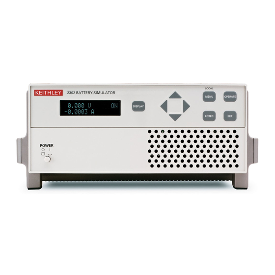
Model 2306 voltage drop during the transmit portion of the pulse ....Model 2302 Specifics 1 Figure F-1 Model 2302 and 2302-PJ single channel battery simulator ....... Test Equipment Depot - 800.517.8431 - 99 Washington Street Melrose, MA 02176 TestEquipmentDepot.com... -
Page 19: List Of Tables
List of Tables Getting Started Table 1-1 Display samples ....................1-11 Table 1-2 Factory defaults (RST) ..................1-12 Table 1-3 Main MENU structure (accessed by pressing the MENU key on the Front Panel) ..................1-15 Basic Power Supply Operation Table 2-1 Current ranges ..................... -
Page 20: Common Commands
Status Structure Table 8-1 Common and SCPI commands — reset registers and clear queues ....Table 8-2 Command commands — status byte and service request enable registers ..Table 8-3 Common and SCPI commands — condition registers ........8-17 Table 8-4 Common and SCPI commands —... -
Page 21: Replaceable Parts
Calibration Table 14-1 Recommended calibration equipment .............. 14-3 Table 14-2 Model 2306 front panel calibration summary ..........14-5 Table 14-3 Remote calibration summary ................14-16 Replaceable Parts Table 16-1 Model 2306 digital board parts list ..............16-3 Table 16-2 Model 2306 analog board parts list ..............16-7 Table 16-3 Model 2306 display board parts list .............. - Page 22 Test Equipment Depot - 800.517.8431 - 99 Washington Street Melrose, MA 02176 TestEquipmentDepot.com...
-
Page 23: Getting Started
• battery and charger channel features contained in this manual apply for the Models 2306, 2306-PJ, and 2306-VS. • only battery channel features contained in this manual apply for the Model 2302 and 2302-PJ Refer to Appendix F for specific Model 2302 and 2302-PJ information. -
Page 24: General Information
Worldwide phone numbers are listed at the front of this manual. Safety symbols and terms Keithley uses a standard set of safety symbols and terms that may be found on an instrument or in its manual. The ! symbol on an instrument indicates that the user should refer to the operating instructions located in the manual. -
Page 25: Inspection
• Quick Disconnect Output/DVM Input Connector (2) • Accessories as ordered • Certificate of calibration • Product Information CD-ROM that contains PDFs of Model 2302/2306 Instruction Manual and Model 2302/2306 Quick Results Guide • Model 2302/2306 Quick Results Guide (Hardcopy) •... -
Page 26: Power Supply Overview
Getting Started Power supply overview The Model 2306 power supply (dual channel battery/charger simulator — see Figure 1-1) can simulate a battery (Channel #1) or a charger (Channel #2). Figure 1-2 shows the Model 2306-VS front and rear panels. NOTE Except where noted, all information in this manual pertaining to the Model 2306 and 2306-PJ also applies to the Model 2306-VS. - Page 27 Getting Started Figure 1-2 Model 2306-VS dual channel battery/charger simulator LOCAL 2306-VS DUAL CHANNEL BATTERY/CHARGER SIMULATOR MENU OPERATE DISPLAY ENTER POWER A) Front Panel WARNING: NO INTERNAL OPERATOR SERVICABLE PARTS,SERVICE BY QUALIFIED PERSONNEL ONLY. ISOLATION FROM EARTH: 22 VOLTS MAX. OUTPUT #1 OUTPUT #2 DVM IN...
- Page 28 Getting Started NOTE When using the power supply as a sink (negative polarity), the power supply is dissi- pating rather than sourcing power (see “Sink Operation” in Section 2). A simplified diagram of the power supply is shown in Figure 1-3.
-
Page 29: Remote Display Option
Getting Started Remote display option NOTE The remote display option cannot be used with the Model 2306-VS If mounting the power supply in a location where the display cannot be seen or the controls are not easily accessible, use the optional Model 2304-DISP or 2306-DISP Display Module (see Figure 1-4). -
Page 30: Power-Up
RAM tests are completed. After a blinking cursor appears on line two, EPROM self tests are completed. NOTE If a problem develops while the instrument is under warranty, return it to Keithley Instruments Inc., for repair. If the instrument passes the self tests, the following information is briefly displayed: Top line —... -
Page 31: Fuse Replacement
Snap the fuse out of the drawer and replace it with the same type (250V, 2.0A, 5 × 20mm time lag). The Keithley part number is FU-81. CAUTION For continued protection against fire or instrument damage, only replace the fuse with the type and rating listed. -
Page 32: Display Modes
1-10 Getting Started Display modes For voltage and current readings, there are four display modes described as follows: • ACTUAL V AND I — This display mode is used to read back the actual output voltage and current. This display mode is the RST default. (See Section 2 for details.) •... -
Page 33: Default Settings
Getting Started 1-11 With the desired mode and active channel displayed, press ENTER. Now the display will reflect this desired mode and active channel. Note that after selecting PULSE CURRENT, use the key to select the desired pulse measurement: pulse high, pulse low, or pulse average. - Page 34 1-12 Getting Started Table 1-2 Factory defaults (RST) Reset (RST) default Setting Battery Channel (#1) Charger Channel (#2) Output value settings: Voltage (V) 0.000V 0.000V Current (A) 0.2500A 0.2500A Output state (operate) OFF Voltage protection 8V, clamp off 8V, clamp off Display type Actual V and I Actual V and I...
- Page 35 Getting Started 1-13 Table 1-2 (cont.) Factory defaults (RST) Reset (RST) default Setting Battery Channel (#1) Charger Channel (#2) Step delay Step range Step trigger level Trigger External (Model 2306-VS) Both NONE NONE Input edge FALLING FALLING Output edge FALLING FALLING Enable Step...
-
Page 36: Setups - Save, Power-On, And Recall
1-14 Getting Started Setups — Save, Power-on, and Recall Setups are configured by SAVE SETUP, POWER ON SETUP and RECALL SETUP items of the MENU (which is accessed by pressing the MENU key). When a setup is saved, all settings that are channel specific settings will be saved to that setup. - Page 37 Getting Started 1-15 Table 1-3 Main MENU structure (accessed by pressing the MENU key on the Front Panel) Menu item Description GPIB ADDRESS Set primary address (0 to 30) Sect. 6 CURRENT RANGE #1/#2 Select current range: Sect. 2 Battery channel (#1) Model 2306/2306-VS Model 2306-PJ Charger channel (#2)
- Page 38 1-16 Getting Started Table 1-3 (cont.) Main MENU structure (accessed by pressing the MENU key on the Front Panel) Menu item Description TRIGGER LEVEL Model 2306, 2306-VS and 2306-PJ — Sets pulse current trig- ger level in Amps on the 5A current range: Battery channel (#1) Charger channel (#2) A(5.0) 0–5A...
-
Page 39: Getting Around The Menu
Getting Started 1-17 Getting around the MENU • Press the MENU key to activate the menu. • Use the keys to scroll through the primary menu items. • Changing channels: When the main menu is displayed, use the keys to change the active channel (each press of the keys will toggle between Channel #1 and Channel #2). -
Page 40: Scpi Programming
1-18 Getting Started SCPI programming SCPI programming information is integrated with front panel operation throughout this manual. SCPI commands are listed in tables, and additional information that pertains exclusively to remote operation is provided after each table. Also, the SCPI tables may reference other sections of this manual. -
Page 41: Basic Power Supply Operation
Basic Power Supply Operation Test connections — Explains how to connect DUT to the power supply output and how • to connect an external voltage to the DVM input. Outputting voltage and current — Explains how to output voltage and current. •... -
Page 42: Test Connections
• battery and charger channel features contained in this manual apply for the Model 2306, 2306-PJ, and 2306-VS • only battery channel features contained in this manual apply for the Model 2302 and 2302-PJ Refer to Appendix F for specific Model 2302 and 2302-PJ information. -
Page 43: Remote Sense
Basic Power Supply Operation Figure 2-1 Four-wire sense connections for battery and charger channels Quick Disconnect Connector DVM Input External Test Circuit DVM + DVM - Source - Source - Sense - Sense + Source + Source + Model 2306 Twisted Pair Source Input/Output Remote sense... -
Page 44: Local Sense
Basic Power Supply Operation Local sense The 2306 battery and charger channels can be connected to operate with local sense leads (2-wire connection) as shown in Figure 2-2. In this connection scheme, the sense inputs and sup- ply outputs are jumpered at the rear of the supply. Figure 2-2 Local sense connections Quick Disconnect... -
Page 45: Outputting Voltage And Current
Basic Power Supply Operation Outputting voltage and current NOTE For the Model 2306-VS, if trigger external is enabled and current limit tripping or VPT occurs, the display is turned on and the output is turned off. See Section Setting voltage protection value NOTE The VPT value (voltage protection value) is channel specific. -
Page 46: Selecting Proper Current Range
Basic Power Supply Operation Selecting proper current range NOTE The current range value is channel specific. The number after the # indicates the channel affected by editing. Power supply current ranges are listed in Table 2-1. With auto range selected, the instrument will automatically go to the most sensitive range to perform the measurement. -
Page 47: Editing Output Voltage And Current Limit Values
Basic Power Supply Operation The power supply may or may not be taken out of current limit by decreasing the output volt- age or increasing the current limit value, depending on how the circuit is connected. However, increasing the current limit may compromise protection for the DUT. While in the current limit, the power supply is operating as a constant-current source. - Page 48 Basic Power Supply Operation (Model 2306-PJ) defaults the current limit setting to 600mA since that is the maximum allowable setting on that range. Toggling back to the 5 amps range reinstates the 3A limit. If the current limit value on the 5 amps range is ð600mA, the limit on the 500mA range will be the same when switching from the 5A range to the 500mA range.
-
Page 49: Pressing Operate
Basic Power Supply Operation Editing shortcuts With the output OFF, the following editing shortcuts can be used: • Output voltage can be quickly set to the maximum value by incrementing the tens digit (MSD). Note that if the tens digit is zero, it is not displayed. Place the cursor to the left of the units digit. -
Page 50: Output Bandwidth
2-10 Basic Power Supply Operation Output bandwidth The battery and charger channel’s output bandwidth control has HIGH and LOW settings. The HIGH setting will result in the fastest response with dynamic loads but, could be unstable with certain loads. The LOW setting mode will have a slower response but will be stable for most loads. -
Page 51: Output Impedance
2-11 Output impedance Keithley’s Model 2306 has a variable output impedance feature on the battery channel (channel #1). This output impedance setting allows the performance of the battery channel to closely model a real battery's performance with a dynamic load. When setting the output... -
Page 52: Scpi Programming - Outputting Voltage And Current
2-12 Basic Power Supply Operation SCPI programming — outputting voltage and current The commands to output voltage and current are summarized in Table 2-3 (a listing following the table contains specific command notes). The programming example (“Outputting and read- ing back V and I”) located at the end of this section demonstrates how to use these commands. NOTE Brackets [ ] indicate optional (and default) command parameters. -
Page 53: Command Notes (Outputting Voltage And Current)
Basic Power Supply Operation 2-13 NOTE Refer to the Programming syntax paragraph of Section 6 for a description of parameters (e.g., <b>, <NRf>, etc.). Command notes (outputting voltage and current) SENSe[1]:CURRent:RANGe <n> Applies to battery channel (#1) SENSe2:CURRent:RANGe <n> Applies to charger channel (#2) After specifying a current value, the instrument will go to the most sensitive range to accommodate that reading. - Page 54 2-14 Basic Power Supply Operation [SOURce[1]]:CURRent:STATe? Applies to battery channel (#1) SOURce2:CURRent:STATe? Applies to charger channel (#2) 1. With the LIMit type selected, this command returns a “1” if the power supply is operat- ing as a constant-current source (current limit reached). With the TRIP type selected, a “1”...
-
Page 55: Reading Back V And I
Basic Power Supply Operation 2-15 Reading back V and I Actual V and I display mode Measured output voltages and currents are displayed with the actual V and I display mode selected. This display mode is selected as follows: NOTE To display measured readings if the instrument is in the settings mode, press the SET key until the blinking stops (the measured readings can then be displayed). -
Page 56: Nplc Rate
2-16 Basic Power Supply Operation NPLC rate The integration (reading) rate of the instrument is specified as a parameter based on the num- ber of power-line cycles (NPLC), where 1 PLC for 60Hz line frequency is 16.67msec (1/60). In general, the fastest integration time (0.01 PLC) results in increased reading noise. The slowest integration time (10 PLC) provides the best common-mode and normal-mode rejection. -
Page 57: Scpi Programming - Measure V And I, And Dvm Input
Basic Power Supply Operation 2-17 SCPI programming — measure V and I, and DVM input The commands to measure output voltage and current, and the DVM input are summarized Table 2-4 (a listing following the table contains specific command notes). The “Programming examples”... -
Page 58: Command Notes (Measure V And I, And Dvm Input)
2-18 Basic Power Supply Operation Command notes (measure V and I, and DVM input) SENSe[1]:FUNCtion <name> Applies to battery channel (#1) SENSe2:FUNCtion <name> Applies to charger channel (#2) 1. The parameter name can instead be enclosed in single quotes (e.g., ‘CURRent’). 2. -
Page 59: Measurement Configuration
Basic Power Supply Operation 2-19 Measurement configuration The NPLC RATE #1/#2 and AVER READINGS #1/#2 for DVM measurements can be checked or changed from the menu (which is accessed by pressing the MENU key). The “#1” (battery channel active) or “#2” (charger channel active) will appear on the top line of the dis- play. -
Page 60: Figure 2-3 Sink Operation
2-20 Basic Power Supply Operation Figure 2-3 Sink operation Model 2306 Charger Circuit Cable Sink + output + sense Charger Supply - sense - output Cable However, in this configuration current compliance may not be reached and current measure- ments may be unstable if I is large. -
Page 61: Programming Examples
Basic Power Supply Operation 2-21 Programming examples Outputting and reading back V and I The following command sequences demonstrate how to output voltage and current, and read back (measure) the actual voltage and current: Battery channel (#1) DISP:CHAN 1 ‘ Select battery channel as active one. VOLT 5 ‘... -
Page 62: Dvm Measurements
2-22 Basic Power Supply Operation DVM measurements The following command sequence demonstrates how to measure voltage applied to the DVM input of the power supply: Battery channel (#1) DISP:CHAN 1 ‘ Set active channel - battery. SENS:FUNC ‘DVM’ ‘ Select the DVM Input function. SENS:NPLC 6 ‘... -
Page 63: Pulse Current Measurements Overview
Model 2306, 2306-PJ, and 2306-VS • only battery channel features contained in this manual apply for the Model 2302 and 2302-PJ Refer to Appendix F for specific Model 2302 and 2302-PJ information. - Page 64 Pulse Current Measurements Overview The power supply can perform current measurements for dynamic loads on either battery channel (#1) or charger channel (#2). The built-in measurements include: • Peak measured current — measures the peak (high) current of the pulse train. •...
-
Page 65: Trigger Level
Pulse Current Measurements Trigger level For the Models 2306, 2306-VS and 2306-PJ on the 5A current range, to avoid false pulse detection, you can use a trigger level of up to 5A. All pulses, noise, or other transients that are less than the set trigger level will be ignored. -
Page 66: Integration Times
Pulse Current Measurements Figure 3-2 Trigger delay for high pulse current measurement Internal Trigger User Trigger Delay Delay (15 μs) Trigger Delay Integration Time High Average High = integration time specified for high measurement time + Trigger Delay Low = integration time specified for low measurement time + Trigger Delay Average = integration time specified for average measurement time + Trigger Delay Trigger Delay = Internal trigger delay (15 μs) + User trigger delay The integration time will not start until the trigger delay period expires after detecting the... -
Page 67: Average Readings Count
Pulse Current Measurements sure to factor in the trigger delay (both internal plus user) when determining integration times (see Figure 3-2). When manually set using the front panel keys, the values are changed in increments of 33.3333μsec. This ensures that an integral value of 33.3333μsec will be selected. NOTE Auto time does not account for user trigger delay —... -
Page 68: Measurement Configuration
Pulse Current Measurements Measurement configuration NOTES Current range is selected from the CURRENT RANGE #1/#2 item of the menu. Integration times, average readings count, trigger delay, trigger level range, and trigger level are set from the PULSE CURRENT item of the menu. Details on integration rate, average readings count, trigger delay, trigger level range, and trigger level are provided in the "Overview"... -
Page 69: Average Readings Count
Pulse Current Measurements AUTO TIME — Use to automatically set the integration times for high, low, and average • pulse-current measurements. These times are based on detecting the pulse and remain until another auto time is performed or the times are manually changed. Auto time accounts for the internal (15μsec) delay but not the user trigger delay. - Page 70 Pulse Current Measurements • TRG LEVEL mA — Model 2306-PJ — Use to specify the trigger level for the 500mA current range (battery channel only). Pulses less than the specified level are not detected. Battery Channel (#1): Model 2306-PJ — On the 500mA current range, the trig- ger level can be set for 500mA, 100mA, or 10mA range: 500mA range 0-500mA in 0.5mA steps.
-
Page 71: Pulse Current Display Mode
Pulse Current Measurements the 100mA range, trigger hysteresis is approximately 0.2mA. If a pulse does not exceed the appropriate hysteresis level, trigger detection will not occur. The three trigger level ranges for the 5A current range on the battery channel (#1) are displayed as follows: 5A Range: PCUR TRIG LEVEL #1... -
Page 72: Pulse Current Measurement Procedure
3-10 Pulse Current Measurements Pulse current measurement procedure The following steps summarize the procedure to perform pulse measurements: Press the MENU key to access the menu. Select PULSE CURRENT #1 or #2 by scrolling through the primary menu items (use keys to scroll). - Page 73 Pulse Current Measurements 3-11 Figure 3-3 Determining voltage and current characteristics Quick Disconnect Connector External Test Circuit DVM + DVM Input DVM - Source - Source - Model 2306 Sense - Source Input/Output Sense + Source + Source + Twisted Pair 0.1 Ω...
- Page 74 3-12 Pulse Current Measurements TRIG NOT DETECTED message The TRIG NOT DETECTED message is displayed when specific TLEV settings coupled with specific TLEV ranges have been set and a trigger has not been detected. Refer to Table 3-1 for the message preconditions. Table 3-1 TRIG NOT DETECTED message TLEV setting...
-
Page 75: Scpi Programming - Pulse Current Measurements
Pulse Current Measurements 3-13 SCPI programming — pulse current measurements The commands for pulse current measurements are summarized in Table 3-2 (a listing following the table contains specific command notes). “Programming examples” on page 3-29 demonstrate how to use these commands. Table 3-2 SCPI commands —... - Page 76 3-14 Pulse Current Measurements Table 3-2 SCPI commands — pulse current measurements (cont.) Command Description Default :MILLiamp <NRf> Model 2306-PJ when on 500mA current range. Set trigger level range (10mA, 100mA, or 500mA). The parameter <NRf> sent with this command causes the trigger to be set with the trigger level setting of HALFamp, HUNDred, or TEN.
-
Page 77: Command Notes (Pulse Current Measurements)
Pulse Current Measurements 3-15 Table 3-2 SCPI commands — pulse current measurements (cont.) Command Description Default SENSe[1] :PCURrent :FAST Enable or disable pulse current fast readings. :SEARch Enable or disable pulse current search. :DETect Enable or disable pulse current detection mode. :TimeOUT Specify length of timeout: 5ms - 32s incrementing in 1ms. - Page 78 SENSe2:PCURrent:TIME:DIGitize <NRf> Applies to charger channel (#2) This command allows you to specify the integration time that occurs when the Model 2302, 2306, 2306-PJ, or 2306-VS is digitizing or in burst mode. (SENS:PCUR:SYNC:STAT is OFF for the particular channel.) Units with firmware version at or below B09 will have digitization occur at the integration rate of 33.3μs.
-
Page 79: Using Fast, Search, And Detect
Pulse Current Measurements 3-17 •OFF or 0 - Disables trigger synchronization and selects pulse current digitization. See “Pulse current digitization” for details on digitizing a current pulse or waveform. :TLEVel Commands A valid trigger level for detecting the pulse is needed whether trigger synchronization is ON or OFF (see :SYNChronize commands above). - Page 80 3-18 Pulse Current Measurements For pulse current, a background reading involves looking for the pulse and optionally gener- ating a reading for the user. The various settings of SEARch, FAST, and DETect allow the user to fine tune the function. This enables the function to perform the desired background readings (if any) between user triggered readings.
- Page 81 Pulse Current Measurements 3-19 • If DETECT ON (only), search time needs to elapse before responding to a bus command. • If SEARCH OFF or FAST ON, search time and TOUT are not incurred while pro- cessing non-user triggered commands (refer to Section 10 of the User’s Manual for examples of user triggered).
- Page 82 3-20 Pulse Current Measurements Table 3-3 PCURrent FAST, SEARch, and DETect commands FAST SEARCH DETECT DESCRIPTION The unit is most responsive to bus commands in this mode. The supply does not wait for TOUT or search time for background pulse current readings and TLEV command checks.
- Page 83 Pulse Current Measurements 3-21 Table 3-3 PCURrent FAST, SEARch, and DETect commands (cont.) FAST SEARCH DETECT DESCRIPTION This mode allows the user to know whether the pulse disappeared before a user-triggered reading is requested. The responsiveness of bus commands is governed by TOUT (if no pulses are detected), or by search time (if pulses are detected).
-
Page 84: Pulse Current Digitization
3-22 Pulse Current Measurements Pulse current digitization The following discussion explains how to digitize a current waveform. A programming example at the end of this section demonstrates proper command sequence for pulse current digitization. Overall steps for digitization: Sync up to desired edge for measurement. After detecting edge, wait for the internal and also any user trigger delay. -
Page 85: Pulse Current Step Method
Pulse Current Measurements 3-23 After any specified delay period expires, the instrument takes the number of readings speci- fied by the average count command: SENS[1]:PCUR:AVER <NRf> Battery Channel (#1) SENS2:PCUR:AVER <NRf> Charger Channel (#2) <NRf> = 1 to 5000 Digitize 1 to 5000 readings. NOTE See “Pulse current digitization”... - Page 86 3-24 Pulse Current Measurements verified for being valid on the new range (discussed in more detail later in this section). Because the Models 2306 and 2306-VS have one current range (5A), this range is always the order of operation. Table 3-4 Setting UP and DOWN commands Command Description...
-
Page 87: Trigger Level Settings
Pulse Current Measurements 3-25 Figure 3-5 Sample pulse forms for step method 4 Up 0 Up 5 Up 3 Down 4 Down 0 Down Figure 3-6 Sample one-shot only pulses for step method 0 Up 5 Up 5 Down 0 Down Trigger level settings The trigger level may be set to a unique value for each active step. - Page 88 3-26 Pulse Current Measurements Figure 3-7 Sample :STEP Pulse measurement Pulse sequences — rising and falling Consider the pulse form in Figure 3-8. This pulse form has three falling (DOWN) level steps followed by three rising (UP) level steps. Since these steps rise and fall to the same steady state current, active steps need to be designated as 6 UP and 0 DOWN to measure the step level cur- rent.
- Page 89 Pulse Current Measurements 3-27 For the active steps, the trigger level may be set to a value appropriate for each rising or falling step, or set to the same value for all active steps. If using the same values for all TLEVx steps, make sure the TLEV value set is appropriate for the smallest step (in Figure 3-8, the TLEV value...
-
Page 90: Timeout Setting
3-28 Pulse Current Measurements Model 2306 measures them first.) Also set TLEV1 for the initial step. This value needs to be appropriate for detecting the first DOWN step as an UP step measurement (in Figure 3-9, this value is set at 750mA). For the UP steps, set the trigger level to a value appropriate for each rising step. -
Page 91: Trigger Level Range
Pulse Current Measurements 3-29 Integration time For the pulse current step method, the integration time is required to be at least 400μsec less than the step duration. This 400μsec allows for the Model 2306 to complete the previous measurement conversion and become ready for the next pulse edge. With this in mind, Table 3- lists appropriate integration times. -
Page 92: Figure 3-1 Pulse Current Measurement
3-30 Pulse Current Measurements Pulse current measurements The following command sequence will return the average of 10 peak pulse current measurements: Battery channel (#1) DISP:CHAN 1 ‘ Sets active channel - battery. SENS:CURR:RANG 5 ‘ Select 5A range. VOLT 15 ‘... - Page 93 Pulse Current Measurements 3-31 Pulse current digitization The following command sequence returns 3600 digitized readings. Battery channel (#1) DISP:CHAN 1 ‘ Sets active channel - battery. SENS:CURR:RANG 5 ‘ Select 5A range. VOLT 15 ‘ Set output voltage to 15V. CURR 0.75 ‘...
-
Page 94: Pulse Current Step Method (Battery Channel Only)
3-32 Pulse Current Measurements Pulse current STEP method (battery channel only) NOTE For the Model 2306-PJ to function correctly, the current range must be selected before selecting the trigger level range. Sample step method The following command sequence measures pulses similar to the one shown in Figure 3-7. - Page 95 Pulse Current Measurements 3-33 One-shot pulse NOTE For the Model 2306-PJ to function correctly, the current range must be selected before selecting the trigger level range. The following command sequence measures pulses similar to the one shown in Figure 3-8 with a one-shot pulse measurement.
- Page 96 3-34 Pulse Current Measurements Continuous pulse train NOTE For the Model 2306-PJ to function correctly, the current range must be selected before selecting the trigger level range. The following command sequence measures pulses similar to the one shown in Figure 3-9 a continuous pulse train.
- Page 97 • battery and charger channel features contained in this manual apply for the Models 2306, 2306-VS and 2306-PJ • only battery channel features contained in this manual apply for the Model 2302 and 2302-PJ Refer to Appendix F for specific Model 2302 and 2302-PJ information.
- Page 98 Long Integration Measurements Overview Long integration is an average current measurement of one or more pulses that can be per- formed on either the battery channel or the charger channel. The integration time can be as long as 60 seconds. Since long integration is an average measurement, the integration time should be a complete pulse period or an integral number of pulse periods.
- Page 99 Long Integration Measurements Figure 4-1 > 200ms < 200ms Steady state for waveforms based on low pulse times Steady Steady state state Integration time The integration time period can be set automatically or manually by the user. The integration time can be as long as 60 seconds. For 60Hz power line frequency, the minimum integration time setting is 850msec.
-
Page 100: Pulse Timeout
Long Integration Measurements Trigger level Before a rising or falling pulse edge can trigger the start of a long integration, the pulse must first be detected. Trigger level specifies the minimum pulse level that will cause detection. For example, if the trigger level is set for 2A, pulses that are ≥2A will be detected. Current pulses <2A are ignored. - Page 101 Long Integration Measurements Figure 4-2 Long integration, search, and reading time comparison TOUT Search time Long integration Reading time time Summarizing Figure 4-2: Reading begins searching for high pulse at point (A). Earliest pulse detected at point (B). Reading time equals Long integration time. NOTES •...
- Page 102 Long Integration Measurements NOTES For GPIB operation: 1. use :SEARch to disable the search for pulses (see the :SEARch command in Table 4-2). 2. :FAST (enables a fast readings mode) can be used with long integration function- ality (see the :FAST command in Table 4-2).
-
Page 103: Measurement Configuration
Long Integration Measurements Measurement configuration NOTE Current range is selected from the CURRENT RANGE #1/#2 item of the menu. Integration time, trigger edge, trigger level range, trigger level, and pulse timeout are set from the LONG INTEGRAT #1/#2 item of the menu. Details on integration time, trigger edge, trigger level range, trigger level, and pulse timeout are provided in the “Overview”. -
Page 104: Pulse Timeout
Long Integration Measurements AUTO TIME searches for two consecutive RISING edges. (The setting of trigger edge does not affect AUTO TIME.) Therefore, with NEITHER edge set, the PTT (Pulse Trigger Timeout) bits in the status model may get set. (See section 8 on the status model for more information.) Although autotime does not use the user setting for trigger edge, the user setting will be used for trigger com- mands (e.g., READ?, MEASure?, etc.). - Page 105 Long Integration Measurements The three trigger level ranges are displayed as follows using the TRIGGER LEVEL menu option: 5A Range: LINT TRIG LEVEL #1 A (5.0) 0.000A 1A Range: LINT TRIG LEVEL #1 A (1.0) 0.000A 100mA Range: LINT TRIG LEVEL #1 mA (100) 0.0000A For Model 2306-PJ (battery channel #1) 500mA current range —...
-
Page 106: Long Integration Display Mode
4-10 Long Integration Measurements Long integration display mode Long integration measurements are displayed with the long integration display mode selected. This display mode is selected as follows: NOTE To display measured readings if the instrument is in the settings mode, press the SET key until the blinking stops (the measured readings can then be displayed). -
Page 107: General Notes
Long Integration Measurements 4-11 indicates that the integration time has not been updated. To update the integration time, you will have to again select AUTO TIME after the output is turned ON. Press the DISPLAY key and select the LONG INTEGRATION display type for the desired channel. - Page 108 4-12 Long Integration Measurements LONG INTEGRAT #1/#2. (Select LONG INTEGRAT #1 for the battery channel and LONG INTEGRAT #2 for the charger channel.) Select and adjust the TRIGGER LEVEL and press ENTER. The unit starts looking for the rising edge of the pulse (this is regardless of the trigger edge setting). If the trigger level is still too low or too high, the “LONG INT TRIG NOT DETECTED”...
-
Page 109: Scpi Programming
Long Integration Measurements 4-13 NOTE Setting the trigger level and/or the trigger range may cause “LONG INT TRIG NOT DETECTED” to appear. SCPI programming The commands for long integration measurements are summarized in Table 4-2 (a listing fol- lowing the table contains specific command notes). “Programming examples”... - Page 110 4-14 Long Integration Measurements Table 4-2 SCPI commands — long integration measurements (cont.) Command Description Default :SENSe[1] :LINTegration :TLEVel <NRf> :RANGe <NRf> :MILLiamp <NRf> Model 2306-PJ when on 500mA current range. Set trigger level range (10mA, 100mA, or 500mA). The parameter <NRf> sent with this command causes the trigger to be set with the trigger level setting of HALFamp, HUNDred, or TEN.
-
Page 111: Command Notes (Long Integration Measurements)
Long Integration Measurements 4-15 Command notes (long integration measurements) SENSe[1]:FUNCtion ‘LINTegration’ Applies to battery channel (#1) SENSe2:FUNCtion ‘LINTegration’ Applies to charger channel (#2) The parameter name can be enclosed in single or double quotes (single — shown above, double — shown in Table 4-2). SENSe[1]:LINTegration:SEARch <b>... -
Page 112: Figure 4-3 Tout And Search Time
4-16 Long Integration Measurements Figure 4-3 TOUT TOUT and search time Search Time Long Integration Reading Time Time NOTE • If a pulse is not present, timeout needs to elapse (TOUT). • If DETECT ON (only), search time needs to elapse before responding to a bus command (reading time not incurred). - Page 113 Long Integration Measurements 4-17 Table 4-3 FAST, SEARch, and DETect command reference (cont.) FAST SEARch DETect Description The unit is more responsive to bus commands in this mode since the supply does not need to wait for TOUT or search time plus reading time for background readings. How- ever, the supply does need to wait for TOUT or search time when checking the parameter setting for TLEV commands.
- Page 114 4-18 Long Integration Measurements Table 4-3 FAST, SEARch, and DETect command reference (cont.) FAST SEARch DETect Description With DETect OFF, background long integration measurements will occur between user- triggered readings as well as pulse detection. If the pulse is detected, the front panel will display "LONG INT"...
-
Page 115: Programming Examples
Long Integration Measurements 4-19 Programming examples The battery channel programming example applies to the Models 2306, 2306-VS, and 2306-PJ on the 5A current range. To modify the example for the 500mA current range (Model 2306-PJ only): Change the SENS:CURR:RANG command line to select the 500mA current range. Change the trigger level commands to appropriate commands for the 500mA current range. - Page 116 4-20 Long Integration Measurements Test Equipment Depot - 800.517.8431 - 99 Washington Street Melrose, MA 02176 TestEquipmentDepot.com...
-
Page 117: Relay Control
• the Model 2306-VS cannot be used for relay control • only battery channel features contained in this manual apply for the Model 2302 and 2302-PJ Refer to Appendix F for specific Model 2302 and 2302-PJ information. Information contained in this section applies to all power supply channels (unless otherwise noted). -
Page 118: Overview
Relay Control Overview The power supply can be used to control up to four external relays. The control circuit is made up of four peripheral drivers, a +5VDC source (250mADC maximum), a coil diode suppression connection, and a chassis ground return. The drive for the relay may be provided by the supplied +5VDC source or an external DC voltage source. -
Page 119: Figure 5-1 External Source Relay Control
Relay Control Figure 5-1 External source relay control CAUTION For external source relay control: -Do not exceed 100mA DC per channel -Do not exceed +24V DC Power Supply Relay Control Relay External Source Coil Pin 5 Relay 1 24VDC Relay 2 Pin 4 4 3 2 Pin 2... -
Page 120: Connections
Relay Control Connections An external relay circuit is connected to the power supply via the 9-pin D-SUB connector located on the rear panel. Table 5-1 contains pinouts and connections for this connector. The illustration provides terminal identification for the conductors of the plug. Figure 5-3 4 3 2 Relay connector (9-pin D-sub) -
Page 121: Controlling Relays
Relay Control Controlling relays The external relays (whether powered by the external or internal source) are controlled from the main menus’s OUTPUT RELAYS menu item. (The main menu is accessed by pressing the MENU key.) Each of the four output relays can be controlled from this menu. NOTE Table 1-3 shows the menu structure. -
Page 122: Scpi Programming
Relay Control SCPI programming Table 5-2 SCPI command — output relay control Command Description Default OUTPut[1] OUTPut subsystem fro Channel #1 (battery channel): :RELay1 <name> Close (ONE) or open (ZERO) relay control circuit ZERO for relay 1. :RELay2 <name> Close (ONE) or open (ZERO) relay control circuit ZERO for relay 2. -
Page 123: External Triggering (Model 2306-Vs Only)
External Triggering (Model 2306-VS Only) • Overview — Describes the additional triggering and voltage step capabilities of the Model 2306-VS. • Trigger Connections — Explains how to use the additional trigger connectors on the rear panel of the Model 2306-VS. •... -
Page 124: Overview
External Triggering (Model 2306-VS Only) Overview NOTE Refer to the hardcopy included with the shipment of the Model 2306-VS External Trigger Functionality Flowchart for more information on external triggering. The Model 2306-VS has four rear panel mounted BNC connectors (two inputs and two out- puts) allowing external triggering and handshaking for both channels. -
Page 125: Trigger Connections
External Triggering (Model 2306-VS Only) Figure 6-1 Typical trigger sequence Trigger Trigger Trigger Trigger Out (1) Out (6) Delay Meas. Numbered sequence shown on first step correspond to Step Meas. Delay Step steps in “Typical trigger Output sequence” (see text). Voltage Step (3) Delay Meas. -
Page 126: Trigger Signals
External Triggering (Model 2306-VS Only) Trigger signals General waveforms for the trigger signals are shown in Figure 6-3 Figure 6-4. Note that both input and output triggers may be programmed for either rising-edge or falling-edge operation (see “Commands” topic later in this section). Figure 6-3 Trigger input signal Triggers Step On... -
Page 127: Commands
External Triggering (Model 2306-VS Only) Commands Commands specific to Model 2306-VS external trigger operation are listed in Table 6-1. Detailed command descriptions follow the table. Table 6-1 Model 2306-VS external trigger commands Command Description Default TRIGger[1] TRIGger subsystem for Channel #1 (battery channel): :EXTernal Path for external trigger control under TRIGger subsystem. -
Page 128: Command Notes
External Triggering (Model 2306-VS Only) Table 6-1 (cont.) Model 2306-VS external trigger commands Command Description Default TRIGger2 TRIGger subsystem for Channel #2 (charger channel): :EXTernal Path for external trigger control under TRIGger2 subsystem. :BOTH <name> Select channel both control type (NONE, VOLT, or AUTO). NONE :EDGE Path for specifying the trigger in &... - Page 129 External Triggering (Model 2306-VS Only) TRIGger[1]:EXTernal:EDGE:IN <name> Applies to battery channel (#1) TRIGger2:EXTernal:EDGE:IN <name> Applies to charger channel (#2) These commands select the polarity of the trigger in signal. With RISING selected, the unit will trigger on the rising edge of the trigger in signal. With FALLING selected, the unit will trigger on the falling edge of the trigger in signal.
- Page 130 External Triggering (Model 2306-VS Only) Once a channel is enabled, a settings conflict error message will occur when: Trying to change a trigger external setting while a channel's trigger external enable is ON. Error message: “+234, Trigger external setting channel enabled conflict.” Error +234 will be generated if BOTH = VOLT or AUTO for channel having TRIG:EXT:ENAB OFF command or the other channel has BOTH set to VOLT/AUTO with external trigger enabled.
- Page 131 External Triggering (Model 2306-VS Only) TRIGger[1]:EXTernal:STEP <NRf1,NRf2,NRf3> Applies to battery channel (#1) TRIGger2:EXTernal:STEP <NRf1,NRf2,NRf3> Applies to charger channel (#2) These commands set the voltage and delay values for a given step. <NRf1> is the step number being configured. This parameter has a minimum setting of 1 and a maximum setting of 20.
- Page 132 6-10 External Triggering (Model 2306-VS Only) TRIGger[1]:EXTernal:STEP:VOLTage <b> Applies to battery channel (#1) TRIGger2:EXTernal:STEP:VOLTage <b> Applies to charger channel (#2) These commands are used to change voltage stepping from ON or OFF. If ON, the voltage will step when the trigger in pulse is detected. If OFF, no voltage stepping is performed when the trigger in pulse is detected.
- Page 133 External Triggering (Model 2306-VS Only) 6-11 features, the setting is ignored, and VPT operates normally. If set to OFF (disabled), the unit does not monitor for a VPT condition while using the TRIGger:EXTernal features. If the delta step size (difference between two voltage steps) is greater or equal to the SOUR:VOLT:PROT setting (*RST default is 8V) then, a VPT condition may occur.
-
Page 134: External Trigger Sequences
6-12 External Triggering (Model 2306-VS Only) Channel with BOTH AUTO has STEP:VOLT ON or STEP:READ is not AUTO with BOTHON parameter for BOTHTRIGEXT command. Error message: “+228, Both auto has step volt or step read conflict” Channel one and two have different values for STEP:POINts with ONEON or TWOON parameters. - Page 135 External Triggering (Model 2306-VS Only) 6-13 For optimal speed, have trigger external enabled on both channels even if you intend to use only a single channel. The trigger in and trigger out pulse may be configured to occur on the RISING or FALLING edge of the pulse based on the setting of the TRIG:EXT:EDGE commands for IN and OUT.
- Page 136 6-14 External Triggering (Model 2306-VS Only) sink or power supply becoming too hot. This is done to handle the situation where the supply is constantly being driven by trigger in pulses. As soon as the trigger out pulses for a channel, a trigger in pulse can be generated for that channel. If this happens too quickly, the unit is constantly handling the trigger external features and has little time, if any, to handle other tasks like front panel, bus commands, and detecting current limiting.
- Page 137 External Triggering (Model 2306-VS Only) 6-15 Table 6-2 (cont.) External trigger sequences for various operating modes (cont.) BOTH VOLT READ Sequence After Detecting Trigger In Pulse AUTO (See programming example number 2.) 1. The channel voltage will step. 2. The step delay setting will elapse. 3.
-
Page 138: Programming Examples
6-16 External Triggering (Model 2306-VS Only) Programming examples Example 1. Measure the high current in a chain of GSM signal with triggering. Model 2306-VS configuration using channel 1: *RST ‘ reset the unit :VOLT 6 ‘ set voltage :CURR 2.25 ‘... - Page 139 External Triggering (Model 2306-VS Only) 6-17 Example 2. Voltage step and measure high current in a chain of GSM signal Model 2306-VS configuration using channel 1: *RST ‘ reset the unit :VOLT 6 ‘ set voltage :CURR 2.25 ‘ set current :SENS:PCUR:FAST ON ‘...
- Page 140 6-18 External Triggering (Model 2306-VS Only) Example 3. Voltage step both channels and measure voltage both channels 2306-VS configuration using channel 1 for voltage stepping and channel 2 for measurements: *RST ‘ reset the 2306-VS :VOLT 0 ‘ set the voltage :CURR 1.75 ‘...
- Page 141 External Triggering (Model 2306-VS Only) 6-19 Example 4. Measure current on both channels using channel 2 Model 2306-VS configuration using channel 2 for current measurements on both channels: *RST ‘ reset the 2306-VS :VOLT 3 ‘ set the voltage :CURR 1.75 ‘...
- Page 142 6-20 External Triggering (Model 2306-VS Only) Example 5. Voltage step only on channel 1 Model 2306-VS configuration using channel 1 for voltage stepping and normal functionality on channel 2: *RST ‘ reset the 2306-VS :VOLT 0 ‘ set the voltage :CURR 1.75 ‘...
-
Page 143: Gpib Operation
Models 2306, 2306-VS and 2306-PJ • only battery channel features contained in this manual apply for the Model 2302 and 2302-PJ Refer to Appendix F for specific Model 2302 and 2302-PJ information. -
Page 144: Introduction
CONTINUED PROTECTION AGAINST FIRE HAZARD,REPLACE FUSE WITH SAME TYPE AND RATING. IEEE-488 Connector NOTE To minimize interference caused by electromagnetic radiation, use only shielded IEEE-488 cables. Available shielded cables from Keithley are Models 7007-1 and 7007-2. Test Equipment Depot - 800.517.8431 - 99 Washington Street Melrose, MA 02176 TestEquipmentDepot.com... - Page 145 GPIB Operation For a multi-unit test system, you can daisy-chain the instruments to the controller by connecting an IEEE cable from one unit to another. Figure 7-2 shows a typical multi-unit connecting scheme daisy chaining. Although any number of connectors could be stacked on one instrument's GPIB port, avoid possible mechanical damage by not stacking more than three.
-
Page 146: Primary Address
GPIB Operation Primary address The power supply ships from the factory with a GPIB address of 16. You can set the address to a value of 0 to 30. Do not assign the same address to another device or to a controller that is on the same GPIB bus. -
Page 147: Long Integration Readings
GPIB Operation Long integration readings When taking long integration readings, make sure to set the timeout value longer than the integration time. For example, if the integration period is 15 seconds, set the “GPIB timeout for > responses” 15000. Setting the “GPIB timeout for responses” greater than the integration time ensures that a GPIB timeout does not occur while the Model 2306 is integrating the reading. -
Page 148: General Bus Commands
GPIB Operation General bus commands General bus commands are those commands, such as DCL, that have the same general mean- ing regardless of the instrument. Table 7-1 lists applicable general bus commands. Table 7-1 General bus commands Command Effect on power supply Goes into remote when next addressed to listen. -
Page 149: Llo (Local Lockout)
GPIB Operation LLO (local lockout) Use the LLO command to prevent local operation of the instrument. After the unit receives LLO, all its front panel controls except POWER are inoperative. In this state, pressing the LOCAL key will not restore control to the front panel. The GTL command restores control to the front panel. -
Page 150: Front Panel Aspects Of Gpib Operation
GPIB Operation Front panel aspects of GPIB operation The following paragraphs describe aspects of the front panel and remote panel that are part of GPIB operation, including the remote operation indicator, LOCAL key, and messages. Remote indicator and LOCAL key When the power supply is in the remote state, the “R”... -
Page 151: Programming Syntax
GPIB Operation Programming syntax The information in the following paragraphs covers syntax for both common commands and SCPI commands. For information not covered here, refer to Section 9 for common commands or to Section 12 for SCPI commands. Also refer the IEEE-488.2 and SCPI standards. Command words Program messages are made up of one or more command words and parameters. -
Page 152: Query Commands
7-10 GPIB Operation • <NRf> Numeric representation format — This parameter is a number that can be expressed as an integer (e.g., 8), a real number (e.g., 23.6), or an exponent (2.3E6). Example: SENSe[1]:AVERage 5Set average count value to 5 for battery channel (#1) •... -
Page 153: Case Sensitivity
GPIB Operation 7-11 Case sensitivity Common commands and SCPI commands are not case sensitive. You can use upper or lower case and any case combination. Examples: *RST = *rst :DATA? = :data? :STATus:PRESet = :status:preset Long-form and short-form versions A SCPI command word can be sent in its long-form or short-form version. The command subsystem tables in Section 12 provide the long-form version. -
Page 154: Single Command Messages
7-12 GPIB Operation Program messages A program message is made up of one or more command words sent by the computer to the instrument. Each common command is a three letter acronym preceded by an asterisk (*). SCPI commands are categorized in the subsystem. For example, :STATus subsystem will be used to help explain how command words are structured to formulate program messages. -
Page 155: Command Path Rules
GPIB Operation 7-13 Command path rules • Each new program message must begin with the root command, unless it is optional (e.g., [:SOURce1]). If the root is optional, treat a command word on the next level as the root. • The colon (:) at the beginning of a program message is optional and need not be used. -
Page 156: Sending A Response Message
7-14 GPIB Operation Response messages A response message is the message sent by the instrument to the computer in response to a query command program message. Sending a response message After sending a query command, the response message is placed in the output queue. When the power supply is then addressed to talk, the response message is sent from the output queue to the computer. -
Page 157: Status Structure
Models 2306, 2306-VS and 2306-PJ • only battery channel features contained in this manual apply for the Model 2302 and 2302-PJ Refer to Appendix F for specific Model 2302 and 2302-PJ information. -
Page 158: Overview
Status Structure Overview The power supply provides a series of status registers and queues allowing the operator to monitor and manipulate the various instrument events. The status structure is shown in Figure 8-1. The heart of the status structure is the status byte register. This register can be read by the user’s test program to determine if a service request (SRQ) has occurred, and what event caused it. - Page 159 Status Structure 8-3 Figure 8-1 Questionable Event Registers Event Status model structure Condition Event Enable Register Register Register & & & & & & & Logical & Calibration Summary & & & & Error Queue & & & & (Always Zero) :CONDition? [:EVENt]? :ENABle <NRf>...
-
Page 160: Clearing Registers And Queues
Status Structure Clearing registers and queues When the power supply is turned on, the bits of all registers in the status structure are clear (reset to 0) and the two queues are empty. Commands to reset the event and event enable registers, and the error queue are listed in Table 8-1. -
Page 161: Programming And Reading Registers
Status Structure 8-5 Programming and reading registers Programming enable registers The enable registers can be programmed by the user. All other registers in the status structure are read-only registers. The following explains how to ascertain the parameter value for the various commands used to program enable registers. -
Page 162: Status Byte And Service Request (Srq)
Status Structure Status byte and service request (SRQ) Service request is controlled by two 8-bit registers; the status byte register and the service request enable register. Figure 8-3 shows the structure of these registers. Figure 8-3 Status byte and service request Status Summary Messages (6) Service Status Byte... -
Page 163: Status Byte Register
Status Structure 8-7 Status byte register The summary messages from the status registers and queues are used to set or clear the appropriate bits (B0, B2, B3, B4, B5, and B7) of the status byte register. These summary bits do not latch, and their states (0 or 1) are solely dependent on the summary messages (0 or 1). -
Page 164: Service Request Enable Register
Status Structure Service request enable register The generation of a service request is controlled by the service request enable register. This register is programmed by the user and is used to enable or disable the setting of bit B6 (RQS/ MSS) by the status summary message bits (B0, B2, B3, B4, B5, and B7) of the status byte register. -
Page 165: Status Byte And Service Request Commands
Status Structure 8-9 Status byte and service request commands The commands to program and read the status byte register and service request enable regis- ter are listed in Table 8-2. For details on programming and reading registers, see “Programming enable registers” “Reading registers”... -
Page 166: Status Register Sets
8-10 Status Structure Status register sets As shown in Figure 8-1, there are four status register sets in the status structure of the power supply: standard event status, operation event status, measurement event status and questionable event status. Register bit descriptions Standard event status The used bits of the standard event register (shown in Figure... - Page 167 Status Structure 8-11 Figure 8-4 Standard event status Standard Event *ESR? (B15 - B8) Register (B2) (B1) (B7) (B6) (B5) (B4) (B3) (B0) & & & To ESB Bit & of Status Byte Register & & & *ESE <NRf> Standard Event *ESE? (B15 - B8) (B2) (B1)
- Page 168 8-12 Status Structure Operation event status The used bits of the operation event register (shown in Figure 8-5) are described as follows: • Bit B1, voltage protection channel #1 (VPT1) — Set bit indicates that the battery channel (#1) is in voltage protection mode. In this mode, the output has been turned off and the front panel displays “VPT”.
- Page 169 Status Structure 8-13 Figure 8-5 Operation event status Operation Condition CLT1 VPT1 CLT2 VPT2 :CONDition? (B2) (B1) (B0) (B8) (B7) (B15-B9) (B6) (B5) (B4) (B3) Register Operation Event CLT2 CLT1 VPT2 VPT1 [:EVENt]? (B2) (B1) (B0) (B8) (B15-B9) (B7) (B6) (B5) (B4) (B3)
- Page 170 8-14 Status Structure Measurement event status The used bits of the measurement event register (shown in Figure 8-6) are described as follows: • Bit B3, reading overflow #1 (ROF1) — Set bit indicates that the battery channel’s (#1) reading exceeds the measurement range of the instrument. (Battery channel only — for the charger channel, see Bit 6.) •...
- Page 171 Status Structure 8-15 Figure 8-6 Measurement event status Measurement RAV2 PTT2 ROF2 RAV1 PTT1 ROF1 :CONDition? Condition (B10) (B9) (B8) (B6) (B5) (B3) (B15-B10) (B4) (B2-B0) Register ROF2 RAV1 PTT1 ROF1 RAV2 PTT2 Measurement [:EVENt]? (B9) (B8) (B7) (B6) Event Register (B15-B10) (B10) (B5)
-
Page 172: Questionable Event Status
8-16 Status Structure Questionable event status The used bit of the questionable event register (shown in Figure 8-7) is described as follows: • Bit B8, calibration summary (Cal) — Set bit indicates that an invalid calibration constant was detected during the power-up sequence. This error will clear after successful calibration of the power supply. -
Page 173: Condition Registers
Status Structure 8-17 Condition registers Figure 8-1 shows, each status register set (except the standard event register set) has a condition register. A condition register is a real-time, read-only register that constantly updates to reflect the present operating conditions of the instrument. For example, when a current pulse is not detected on the battery channel, bit B4 (PTT1) of the measurement condition register will be set (1). -
Page 174: Event Enable Registers
8-18 Status Structure Event enable registers Figure 8-1 shows, each status register set has an enable register. Each event register bit is logically ANDed (&) to a corresponding enable bit of an enable register. Therefore, when an event bit is set and the corresponding enable bit is set (as programmed by the user), the output (summary) of the register will set to 1, which in turn sets the summary bit of the status byte register. -
Page 175: Programming Example - Program And Read Measurement Event Register
Status Structure 8-19 Programming example — program and read measurement event register The following command sequence enables the battery channel (#1) buffer full bit (B9) of the measurement register set, and then reads the event register. After the programmed number of readings (average count) have been taken, reading the event register will return a value that has bit 9 set (bit 9 has a decimal value of 512). -
Page 176: Output Queue
“0, No Error” is placed in the queue. Messages in the error queue are preceded by a code number. Negative (-) numbers are used for SCPI defined messages, and positive (+) numbers are used for Keithley defined messages. The messages are listed in Appendix B. -
Page 177: Programming Example - Read Error Queue
2. Power-up enables error messages and disables status messages. *CLS and STATus:PRESet have no effect. Programming example — read error queue STAT:QUE:ENAB (+000:+900) ‘ Enable all Keithley defined messages (dis- able all SCPI defined messages). STAT:QUE? ‘ Return oldest message. - Page 178 8-22 Status Structure Test Equipment Depot - 800.517.8431 - 99 Washington Street Melrose, MA 02176 TestEquipmentDepot.com...
-
Page 179: Common Commands
Models 2306, 2306-VS and 2306-PJ • only battery channel features contained in this manual apply for the Model 2302 and 2302-PJ Refer to Appendix F for specific Model 2302 and 2302-PJ information. -
Page 180: Overview
Common Commands Overview Common commands are device commands that are common to all devices on the bus. These commands are designated and defined by the IEEE-488.2 standard. Common commands are listed in Table 9-1. Note that detailed information on the Common Commands to program and read status registers is provided in Section 8. -
Page 181: Command Notes (Ieee-488.2 Common Commands And Queries)
Reads identification code The identification code includes the manufacturer, model number, serial number, and firm- ware revision levels as follows: KEITHLEY INSTRUMENTS INC., MODEL 2306, xxxxxxx, yyyyy/zzzzz KEITHLEY INSTRUMENTS INC., MODEL 2306-PJ, xxxxxxx, yyyyy/zzzzz KEITHLEY INSTRUMENTS INC., MODEL 2306-VS, xxxxxxx, yyyyy/zzzzz Where: xxxxxxx is the serial number. - Page 182 Common Commands Send *OPC or *OPC?, separated by a semicolon, on the same line with a query (see Ref. A Table 9-2). If sent on separate lines, an error occurs (B). *OPC or *OPC? can also be sent on the same line or a separate line with a command that is not a query (C and D). Table 9-2 *OPC and *OPC? commands *OPC...
- Page 183 Common Commands *RST — reset Return power supply to RST defaults When the *RST command is sent, the power supply performs the following operations: 1. Returns the instrument to the RST default conditions (see “Default” column of SCPI tables). 2. Cancels all pending commands. 3.
- Page 184 Common Commands Test Equipment Depot - 800.517.8431 - 99 Washington Street Melrose, MA 02176 TestEquipmentDepot.com...
-
Page 185: Signal Oriented Measurement Commands
Models 2306, 2306-VS and 2306-PJ • only battery channel features contained in this manual apply for the Model 2302 and 2302-PJ Refer to Appendix F for specific Model 2302 and 2302-PJ information. -
Page 186: Overview
10-2 Signal Oriented Measurement Commands Overview The signal oriented measurement commands are used to acquire readings. You can use these high-level instructions to control the measurement process. These commands are summarized Table 10-1. Table 10-1 Signal oriented measurement command summary Command Description :FETCh[1]? -
Page 187: Command Notes (Signal Oriented Measurement Commands And Queries)
Signal Oriented Measurement Commands 10-3 NOTE For all array queries, make sure the computer’s buffer is large enough to accommodate all array readings. Overflow readings exponential format = +9.9E37. For all non-array queries, the overflow readings exponential format also = +9.9E37. Command notes (Signal oriented measurement commands and queries) :FETCh[1]? Return last reading for the battery channel... - Page 188 10-4 Signal Oriented Measurement Commands :READ[1]? Trigger and return reading for the battery channel (#1) :READ[1]:ARRay? Trigger and return array of readings for the battery channel (#1) :READ2? Trigger and return reading for the charger channel (#2) :READ2:ARRay? Trigger and return array of readings for the charger channel (#2) The :READ? command is used to trigger and return a single averaged reading, and the :READ:ARRay? command is used to trigger and return an array of readings for the currently...
- Page 189 This allows both channels' triggers to be controlled with a single bus command. The BOTHTRG, BOTHFETCH?, and BOTHREAD? commands work with the Models 2306, 2306-VS, and 2306-PJ, but do not work with the Models 2302 or 2302-PJ (i.e., the commands do not work with single channel models).
- Page 190 10-6 Signal Oriented Measurement Commands Test Equipment Depot - 800.517.8431 - 99 Washington Street Melrose, MA 02176 TestEquipmentDepot.com...
-
Page 191: Display, Format, And System
Models 2306, 2306-VS and 2306-PJ • only battery channel features contained in this manual apply for the Model 2302 and 2302-PJ Refer to Appendix F for specific Model 2302 and 2302-PJ information. -
Page 192: Display Subsystem
11-2 DISPlay, FORMat, and SYSTem DISPlay subsystem The display subsystem controls the display of the power supply and is summarized in Table 11-1. Table 11-1 SCPI commands — display Command Description Default :DISPlay :ENABle <b> Turn display on or off. (see Notes 1, 3) :BRIGhtness <NRf>... - Page 193 DISPlay, FORMat, and SYSTem 11-3 DISPlay:BRIGhtness <NRf> Set brightness for VFD display Parameters <NRf> = 0–1 Blank display: <NRf> = 0 1/4 brightness: <NRf> ≤ 0.25 1/2 brightness: <NRf> ≤ 0.50 3/4 brightness: <NRf> ≤ 0.75 Full brightness: <NRf> ≤ 1.0 This command is ignored if the Model 2306-DISP remote module is connected (the Model 2306-DISP has an LCD display).
-
Page 194: Format Subsystem
11-4 DISPlay, FORMat, and SYSTem DISPlay:TEXT:DATA <a> Define message on display :DISPlay[:WINDow[1]]:TEXT:DATA <a> Parameters <a> = ASCII characters for message Types: String 'aa...a' or "aa...a" Indefinite Block #0aa...a This command defines a text message for the display. A message is made up of 32 characters and starts on the top line of the display and wraps down to the bottom line. -
Page 195: Command Notes (Scpi Commands - Data Format)
DISPlay, FORMat, and SYSTem 11-5 Command notes (SCPI commands — data format) FORMat[:DATA] <type> Select data format Parameters <type> = ASCii ASCII format SREal IEEE754 single precision format DREal IEEE754 double precision format This command is used to select the data format for transferring readings over the bus. The reading(s) that is sent depends on the presently selected function (voltage, current, pulse-current, DVM or long integration). - Page 196 11-6 DISPlay, FORMat, and SYSTem DREal selects the binary IEEE-754 double precision data format and is shown in Figure 11-2 (normal byte order shown). This format is similar to the single precision format except that it is 64 bits long. Figure 11-2 IEEE-754 double precision data format Header...
-
Page 197: System Subsystem
Sec 1* :POSetup <name> Select power-on setup: RST or SAVx where: x = 0 to 4 (2306, 2302); x = 0 to 2 (2306-PJ, 2306-VS, 2302-PJ) :VERSion? Query SCPI revision level. :ERRor Read and clear oldest message in error queue:... -
Page 198: Command Notes (Scpi Commands - System)
SCPI tables. NOTE The Model 2306-PJ, 2306-VS, and 2302-PJ have only SAV0-SAV2 memory locations. With SAV0-4 specified, the power supply powers-on to the setup that is saved in the specified memory location using the *SAV command (Section 9). -
Page 199: Scpi Tables
Models 2306, 2306-VS and 2306-PJ • only battery channel features contained in this manual apply for the Model 2302 and 2302-PJ Refer to Appendix F for specific Model 2302 and 2302-PJ information. -
Page 200: Scpi Command Subsystems Reference Tables
12-2 SCPI Tables SCPI command subsystems reference tables Tables 12-1 to 12-8 summarize the commands for each SCPI subsystem. The following list includes the table numbers and page numbers for each SCPI subsystem command summary. Table TitlePage 12-1 DISPlay command summary..........12-3 12-2 FORMat command... - Page 201 SCPI Tables 12-3 Table 12-1 Display command summary (refer to Display subsystem in Section 11) Command Description Default parameter SCPI :DISPlay :ENABle <b> Enable or disable display. ON (Note 1) :ENABle? Query state of display. :BRIGhtness <NRf> Set brightness for VFD display. 1 (Full brightness) Range 0.000–1.000 Blank display: <NRf>...
- Page 202 12-4 SCPI Tables Table 12-2 FORMat command summary (refer to Format subsystem in Section 11) Command Description Default parameter SCPI :FORMat [:DATA] <type> Specify data format (ASCii, SREal, or ASCii DREal). [:DATA]? Query data format. :BORDer <name> Specify byte order (NORMal or SWAPped SWAPped).
- Page 203 SCPI Tables 12-5 Table 12-3 OUTPut command summary (refer to Tables 2-3 and 5-2) Default Command Description SCPI parameter :OUTPut[1] OUTPut subsystem for channel #1 (battery channel) [:STATe] <b> Turn output ON or OFF. [:STATe]? Query state of output. :BANDwidth Specifies HIGH or LOW bandwidth when the output state is ON and current range is set to 5A.
- Page 204 12-6 SCPI Tables Table 12-4 SENSe command summary (refer to Tables 2-3, 3-2, and 4-2) Default Command Description SCPI parameter :SENSe[1] SENSe subsystem for channel #1 (battery channel) :FUNCtion <name> Select measurement function (“VOLTage,” “CURRent,” VOLT “DVMeter”, “PCURrent,” or “LINTegration”). :FUNCtion? Query measurement function.
- Page 205 SCPI Tables 12-7 Table 12-4 (cont.) SENSe command summary (refer to Tables 2-3, 3-2, and 4-2) (cont.) Default Command Description SCPI parameter :SENSe[1] :PCURrent :TIME (cont.) :HIGH? Query high integration time. :LOW <NRf> Specify integration time (in sec) for low pulse 3.333E-05 measurements (33.33E-06 to 0.8333) —...
- Page 206 12-8 SCPI Tables Table 12-4 (cont.) SENSe command summary (refer to Tables 2-3, 3-2, and 4-2) (cont.) Default Command Description SCPI parameter :SENSe[1] :PCURrent :STEP Step delay: 0msec–100msec (in 10μsec steps). :DELay <NRf> :SEQuence Define up to 19 delay sequence values using the index and the time value (e.g.
- Page 207 SCPI Tables 12-9 Table 12-4 (cont.) SENSe command summary (refer to Tables 2-3, 3-2, and 4-2) (cont.) Default Command Description SCPI parameter :SENSe[1] :PCURrent :SYNChronize :TLEVel Trigger level: [:AMP] <NRf> Set trigger level (in amps) for 5A range on 5A current range: 0.0–5.0.
- Page 208 12-10 SCPI Tables Table 12-4 (cont.) SENSe command summary (refer to Tables 2-3, 3-2, and 4-2) (cont.) Default Command Description SCPI parameter :SENSe[1] :PCURrent :SYNChronize :TLEVel :RANGe Set trigger level range (100mA, 1A, or 5A) for the <NRf> 5A current range. The parameter <NRf> sent with this command causes the trigger to be set with the trigger level setting of MILL, ONE, or AMP.
- Page 209 SCPI Tables 12-11 Table 12-4 (cont.) SENSe command summary (refer to Tables 2-3, 3-2, and 4-2) (cont.) Default Command Description SCPI parameter :SENSe[1] :PCURrent :TimeOUT <NRf> Specify length of timeout: 5ms - 32s incrementing in 1 (sec) 1ms. :TimeOUT? Query pulse current timeout setting. :LINTegration Path to configure long integration measurements (refer to Section 4):...
- Page 210 12-12 SCPI Tables Table 12-4 (cont.) SENSe command summary (refer to Tables 2-3, 3-2, and 4-2) (cont.) Default Command Description SCPI parameter :SENSe[1] :PCURrent :LINTegration :TEN? Model 2306-PJ only — Query the 10mA trigger level setting on the 500mA current range. :RANGe <NRf>...
- Page 211 SCPI Tables 12-13 Table 12-4 (cont.) SENSe command summary (refer to Tables 2-3, 3-2, and 4-2) (cont.) Default Command Description SCPI parameter :SENSe2 :AVERage? Query average count. :CURRent [:DC] Path to configure the current measurement function: :RANGe Current measurement range: [:UPPer] <NRf>...
- Page 212 12-14 SCPI Tables Table 12-4 (cont.) SENSe command summary (refer to Tables 2-3, 3-2, and 4-2) (cont.) Default Command Description SCPI parameter :SENSe2 :PCURrent :TIME :DIGitize? Query integration time for digitizing or burst measurements. :SYNChronize Path for pulse detection triggering: [:STATe] <b>...
- Page 213 SCPI Tables 12-15 Table 12-4 (cont.) SENSe command summary (refer to Tables 2-3, 3-2, and 4-2) (cont.) Default Command Description SCPI parameter :SENSe2 :LINTegration :TIME? :AUTO Power supply sets integrations time. :TLEVel <NRf> Set trigger level value 0–5A. :TLEVel? Query trigger level setting. :TimeOUT <NRf>...
- Page 214 12-16 SCPI Tables Table 12-5 SOURce command summary (refer to Table 2-3) Default Command Description SCPI parameter [:SOURce[1]] SOURce subsystem for channel #1 (battery channel). :VOLTage Path to set output voltage. :PROTection <NRf> Sets VPT offset (0–8V). :PROTection? Query setting for VPT offset. :STATe? Query state of VPT —...
- Page 215 SCPI Tables 12-17 Table 12-5 (cont.) SOURce command summary (cont.) (refer to Table 2-3) Default Command Description SCPI parameter :SOURce2 :CURRent [:LIMit] Path to configure current limit. [:VALue] <NRf> Specify current limit value in amps: 0.006–5 0.25 with 100μA resolution. [:VALue]? Query current limit.
- Page 216 12-18 SCPI Tables Table 12-6 (cont.) STATus command summary (cont.) (refer to Section 8) Default Command Description SCPI parameter :STATus :OPERation :CONDition? Read the condition register. :QUEStionable Path to control the questionable status registers: [:EVENt]? Read the event register. (Note 2) :ENABle <NRf>...
- Page 217 SCPI Tables 12-19 Table 12-7 SYSTem command summary (refer to System subsystem in Section 11) Default Command Description SCPI parameter :SYSTem :VERSion? Query SCPI version level. :ERRor? Read and clear oldest message in error queue. :CLEar Clears error queue. :LFRequnecy? Query power line frequency setting.
- Page 218 12-20 SCPI Tables Table 12-8 Model 2306-VS external trigger command summary (refer to Section 6) Command Description Default SCPI TRIGger[1] Trigger subsystem for Channel #1 (battery channel): :EXTernal Path for external trigger control. :BOTH <name> Select channel both control type (NONE, NONE VOLT, or AUTO).
- Page 219 SCPI Tables 12-21 Table 12-8 Model 2306-VS external trigger command summary (cont.) (refer to Section 6) Command Description Default SCPI TRIGger[1] :EXTernal :STEP? :VPT? Query VPT state. TRIGger2 Trigger subsystem for Channel #2 (charger channel): :EXTernal Path for external trigger control. :BOTH <name>...
- Page 220 12-22 SCPI Tables Table 12-8 Model 2306-VS external trigger command summary (cont.) (refer to Section 6) Command Description Default SCPI TRIGger[2] :EXTernal :STEP? :POINts? Query # of measurements and/or voltage steps. :VPT <b> Enable (ON) or disable (OFF) Voltage Protection Tripping. :VPT? Query VPT state.
-
Page 221: Performance Verification
This manual covers Keithley Models 2302, 2302-PJ, 2306, 2306-PJ, and 2306-VS simulators (power supplies). Since the Model 2302 and 2302-PJ are single channel battery simulators, functions related to the second chan- nel (i.e., the charger channel) are not available for the Model 2302 and 2302- PJ. Therefore: •... -
Page 222: Introduction
NOTE Unless otherwise noted, Model 2306 refers to Models 2306, 2306-PJ, 2306-VS, 2302, and 2302-PJ while Model 2306 (only) refers to the specific Model 2306 (not 2306-PJ, etc.). Other Model numbers refer specifically to their respective models. Use the procedures in this section to verify that Model 2306 accuracy is within the limits stated in the accuracy specifications. -
Page 223: Verification Test Requirements
Performance Verification 13-3 Verification test requirements Be sure that you perform the verification tests: • Under the proper environmental conditions. • After the specified warm-up period. • Using the correct line voltage. • Using the proper test equipment. • Using the specified output signals and reading limits. Environmental conditions Conduct your performance verification procedures in a test environment with: •... -
Page 224: Recommended Test Equipment
Full-range, 90-day, 23°C various measurement points. Characterize resistor using 4-wire ohms function of DMM before use. Required only for Models 2306-PJ and 2302-PJ. Characterize resistor using 4-wire ohms function and 200OHM range of DMM before use. See Resistor considerations for temperature coefficient. -
Page 225: Verification Limits
Performance Verification 13-5 Verification limits The verification limits stated in this section have been calculated using only the Model 2306 accuracy specifications, and they do not include test equipment uncertainty. If a particular measurement falls outside the allowable range, recalculate new limits based both on Model 2306 specifications and corresponding test equipment specifications. -
Page 226: Output Voltage Accuracy
13-6 Performance Verification • Do not connect test equipment to the Model 2306 through a scanner, multiplexer, or other switching equipment. • Be sure that the Model 2306 output is turned on before making measurements. • Allow the unit output signal to settle before making a measurement. Output voltage accuracy Follow the steps below to verify that Model 2306 output voltage accuracy is within specified limits. - Page 227 Performance Verification 13-7 Select the multimeter DC volts measuring function, and enable auto-ranging. Select Channel #1 by pressing the keys to toggle between Channel #1 and Channel #2. Make sure the Model 2306 output is turned on. Verify output voltage accuracy for each of the voltages listed in Table 13-2.
-
Page 228: Voltage Readback Accuracy
13-8 Performance Verification Voltage readback accuracy Follow the steps below to verify that Model 2306 voltage readback accuracy is within specified limits. The test involves setting the source voltage to specific values, as measured by a digital multimeter, and then verifying that voltage readback readings are within required limits. With the power supply’s output off, connect the digital multimeter to the Model 2306 OUTPUT #1 SOURCE and SENSE terminals, as shown in Figure... -
Page 229: Compliance Current Accuracy
Performance Verification 13-9 Compliance current accuracy Follow the steps below to verify that Model 2306/2306-VS/2306-PJ compliance current accuracy is within specified limits. The test involves setting the compliance current to specific values and determining the actual current by measuring the voltages across a characterized 1Ω resistor with a precision digital multimeter. - Page 230 13-10 Performance Verification Select the multimeter DC voltage measuring function, and enable auto-ranging. Select Channel #1 by pressing the keys to toggle between Channel #1 and Channel #2. Turn on the Model 2306 output. Verify compliance current accuracy for the currents listed in Table 13-4.
-
Page 231: Current Readback Accuracy
Performance Verification 13-11 Current readback accuracy Follow the steps below to verify that Model 2306 current readback accuracy is within specified limits. The test involves setting the output current to specific values as measured with a resistor and precision digital multimeter. 5A range readback accuracy With the power supply’s output off, connect the digital multimeter and characterized 1Ω... -
Page 232: 5Ma Range Readback Accuracy
13-12 Performance Verification 5mA range readback accuracy The following test applies to the Models 2306, 2306-VS, and 2302 (not applicable for Models 2306-PJ or 2302-PJ). With the power supply’s output off, connect the digital multimeter and characterized 3kΩ resistor to the Model 2306 OUTPUT #1 terminals, as shown in Figure 13-3. - Page 233 Performance Verification 13-13 Select the multimeter DC volts measuring function, and enable auto-range. Select Channel #1 by pressing the keys to toggle between Channel #1 and Channel #2, then select the 5mA readback range and actual current reading data. Turn on the Model 2306 output. Verify 5mA range current readback accuracy for the currents listed in Table 13-6.
-
Page 234: 500Ma Range Readback Accuracy
13-14 Performance Verification 500mA range readback accuracy With the power supply’s output off, connect the digital multimeter and characterized 30Ω resistor to the Model 2306-PJ OUTPUT #1 terminals, as shown in Figure 13-4. Be sure to observe proper polarity and connections (30Ω resistor between SOURCE + and DMM INPUT HI;... - Page 235 Performance Verification 13-15 Select the multimeter DC volts measuring function, and enable auto-range. Select Channel #1 by pressing the keys to toggle between Channel #1 and Channel #2, then select the 500mA readback range and actual current reading data. Turn on the Model 2306-PJ output. Verify 5mA range current readback accuracy for the currents listed in Table 13-7.
-
Page 236: Digital Voltmeter Input Accuracy
13-16 Performance Verification Digital voltmeter input accuracy Follow the steps below to verify that Model 2306 digital voltmeter input accuracy is within specified limits. The test involves setting the voltage applied to the DVM input to accurate values and then verifying that the Model 2306 digital voltmeter input readings are within required limits. - Page 237 Performance Verification 13-17 Select the DMM DC volts function, and enable auto-ranging. Select Channel #1 by pressing the keys to toggle between Channel #1 and Channel #2, and enable the Model 2306 DVM input. Turn on the Model 2306 source output. Verify digital voltmeter input accuracy for each of the voltages listed in Table 13-8.
- Page 238 13-18 Performance Verification Test Equipment Depot - 800.517.8431 - 99 Washington Street Melrose, MA 02176 TestEquipmentDepot.com...
-
Page 239: Calibration
Models 2306, 2306-VS and 2306-PJ • only battery channel features contained in this manual apply for the Model 2302 and 2302-PJ NOTES Refer to Appendix F for specific Model 2302 and 2302-PJ information. -
Page 240: Introduction
14-2 Calibration Introduction Use the procedures in this section to calibrate the Model 2306. These procedures require accurate test equipment to measure precise DC voltages and currents. Calibration can be performed either from the front panel or by sending SCPI calibration commands over the IEEE-488 bus with the aid of a computer. -
Page 241: Calibration Considerations
“Resistor considerations” later in this section for important temperature coefficient information. Table 14-1 Recommended calibration equipment Description Manufacturer/Model Specifications Digital Multimeter Keithley 2001 DC Voltage 20V: ±22ppm Resistance 20Ω: ±59ppm 20kΩ: ±36ppm Precision Resistor 4Ω, 0.1%, 100W Precision Resistor 3kΩ, 0.1%, 0.125W Full-range, 90-day, 23°C ±5°C accuracy specifications of ranges required for various measurement points. -
Page 242: Resistor Connections
14-4 Calibration Resistor connections When performing calibration steps that use either the 4Ω or 3kΩ resistor, connect the Model 2306 OUTPUT #1 or OUTPUT #2 SENSE leads and DMM test leads as close to the resistor body as possible. Resistor considerations The test resistors should be characterized using the 4-wire ohms function of the DMM recommended in Table 14-1... - Page 243 Calibration 14-5 Press the key. The unit will then prompt you to run calibration: CALIBRATE UNIT Press ENTER. The unit will then prompt for the calibration code: CALIBRATE UNIT Cal Code KI002306 Using the edit keys, set the display to the current calibration code, then press ENTER. (Default: KI002306.) The unit will then prompt you as to whether or not to change the code: CALIBRATE UNIT...
- Page 244 14-6 Calibration Step 2: Perform Channel #1 (battery channel) calibration steps NOTE The unit will display the most recently calibrated values. Factory defaults are shown in this manual. Connect the OUTPUT #1 SOURCE, SENSE, and DVM IN terminals to the DMM, as shown in Figure 14-1.
- Page 245 Calibration 14-7 The unit will prompt you for the DMM reading, which will be used to calibrate the Channel #1 full-scale output voltage: CAL VOLTS CHAN 1 READ1 14.0000 V Using the edit keys, adjust the Model 2306 voltage display to agree with the DMM voltage reading, then press ENTER.
- Page 246 14-8 Calibration At this point, the unit will prompt for 5A Channel #1 full-scale calibration output: CAL 5 A CHAN 1 SET 1.90000 A Using the edit keys, adjust the set value to 1.9000A, then press ENTER. The unit will prompt you for the DMM reading, which calibrates the 5A current limit for Channel #1: CAL 5 A CHAN 1 READ1 1.90000 A...
- Page 247 Calibration 14-9 Figure 14-3 Connections for 5mA range calibration Input HI SENSE Ω 4 WIRE INPUT Input LO OUTPUT #1 connections shown. Use OUTPUT #2 350V 1100V PEAK PEAK for Charger Channel. 2001 MULTIMETER 3k Ω Resistor 500V PEAK INPUTS Ω2 Ω4 PREV...
- Page 248 14-10 Calibration Using the edit keys, adjust the display to agree with the new DMM voltage reading, then press ENTER. The unit will prompt for Channel #2 DVM full-scale calibration: CAL DVM CHAN 2 ALL READY TO DO? Press ENTER to complete Channel #2 DVM full-scale calibration. Connect the digital multimeter volts input and characterized 4Ω...
-
Page 249: Remote Calibration
Calibration 14-11 Step 4: Enter calibration dates, and save calibration After completing all Channel #1 and Channel #2 calibration steps, the unit will prompt if you wish to save calibration: CALIBRATE UNIT Save Cal Data YES To save new calibration constants, select YES, then press ENTER. If you wish to exit calibration without saving new calibration constants, select NO, then press ENTER. -
Page 250: Remote Calibration Procedure
14-12 Calibration Remote calibration procedure Use the following procedure to calibrate the Models 2306. Table 14-3 summarizes the calibration steps in the proper sequence. See Appendix C for command details. NOTES Calibration steps must be performed in the following sequence, or an error will occur. You can abort the procedure and revert to previous calibration constants before :SAVE by sending the :CAL:PROT:LOCK command. - Page 251 Calibration 14-13 Note and record the DMM reading, then send that reading as the parameter for the following command: :CAL:PROT:STEP1 <DMM_Reading> For example, if the DMM reading is 14.012V, the command would be: :CAL:PROT:STEP1 14.012 Note and record a new DMM reading, then send that reading as the parameter for the following command: :CAL:PROT:STEP2 <DMM_Reading>...
- Page 252 14-14 Calibration Note and record the DMM voltage reading, then calculate the current from the voltage reading and actual resistance value. Send that current value as the parameter for the following command: :CAL:PROT:STEP8 <Calculated_Current> Example: for the Model 2306/2306-VS, with a current of 4.5mA, the command would :CAL:PROT:STEP8 4.5E-3 Example: for the Model 2306-PJ, with a current of 450mA, the command would be: :CAL:PROT:STEP8 450E-3...
- Page 253 Calibration 14-15 Note and record the DMM voltage reading, then calculate the current from that reading and 4Ω resistor value. Send the following command using that calculated current as the parameter: :CAL:PROT:STEP14 <Calculated_Current> For example, with a current value of 1.894A, the command would appear as follows: :CAL:PROT:STEP14 1.894 Note and record a new DMM voltage reading, then again calculate the current from the voltage and resistance.
- Page 254 14-16 Calibration Table 14-3 Remote calibration summary Test Step Command Description connections :CAL:PROT:CODE ‘KI002306’ Unlock calibration. None :CAL:PROT:INIT Initiate calibration. None Figure 14-1 :CAL:PROT:STEP0 14 Full-scale (14V) output. Figure 14-1 :CAL:PROT:STEP1 <DMM_Reading> Full-scale output cal. Figure 14-1 :CAL:PROT:STEP2 <DMM_Reading> Full-scale measure cal. Figure 14-1 :CAL:PROT:STEP3 DVM full-scale cal.
-
Page 255: Changing The Calibration Code
Calibration 14-17 Changing the calibration code The default calibration code may be changed from the front panel or via remote as discussed below. Changing the code from the front panel Follow the steps below to change the code from the front panel: Press the MENU key, then choose CALIBRATE UNIT, and press ENTER. -
Page 256: Resetting The Calibration Code
14-18 Calibration Resetting the calibration code If you forget the calibration code, you can unlock calibration and reset the code as outlined below. Refer to Section 15 for more detailed disassembly instructions. WARNING Hazardous voltages are present inside the unit. Use caution to avoid electric shock, which could cause personal injury or death. -
Page 257: Viewing Calibration Date And Count
Calibration 14-19 Viewing calibration date and count Viewing date and count from the front panel Follow the steps below to view the calibration date and count from the front panel: Press the MENU key then choose CALIBRATE UNIT, and press ENTER. The instrument will display the last date calibrated: CALIBRATE UNIT LAST ON 02/01/2003... - Page 258 14-20 Calibration Test Equipment Depot - 800.517.8431 - 99 Washington Street Melrose, MA 02176 TestEquipmentDepot.com...
-
Page 259: Disassembly
Disassembly Test Equipment Depot - 800.517.8431 - 99 Washington Street Melrose, MA 02176 TestEquipmentDepot.com... -
Page 260: Introduction
15-2 Disassembly Introduction This section explains how to handle, clean, and disassemble the Model 2306 — drawings are located at the end of this section. WARNING The procedures in this section are intended only for qualified service personnel. Disconnect the line cord and all test leads and wires from the instrument before disassembling the unit. -
Page 261: Static Sensitive Devices
Use the assembly drawings located at the end of this section to assist you as you disassemble and reassemble the Model 2306. Refer to these drawings for information about the Keithley part numbers of most mechanical parts in the unit. -
Page 262: Disassembly Procedures
15-4 Disassembly Disassembly procedures Case cover removal Follow the steps below to remove the case cover to gain access to internal parts. WARNING Before removing the case cover, disconnect the line cord and any test leads from the instrument. Remove handle — The handle serves as an adjustable tilt-bail. Adjust its position by gently pulling it away from the sides of the instrument case and swinging it up or down. -
Page 263: Digital Board Removal
Disassembly 15-5 Digital board removal Perform the following steps to remove the digital board. This procedure assumes that the analog board assembly has already been removed. Remove the IEEE-488 connector fasteners that attach the connector to the rear panel. Disconnect all cables and wires connected to the digital board. Remove the front panel by prying out the four retaining clips while pulling the front panel away from the chassis. -
Page 264: Instrument Reassembly
15-6 Disassembly Instrument reassembly Reassemble the instrument by reversing the previous disassembly procedures. Make sure that all parts are properly seated and secured, and that all connections are properly made. WARNING To ensure continued protection against electrical shock, verify that power line ground (green and yellow wire attached to the line filter module) is connected to the chassis. -
Page 265: Replaceable Parts
Replaceable Parts Test Equipment Depot - 800.517.8431 - 99 Washington Street Melrose, MA 02176 TestEquipmentDepot.com... -
Page 266: Introduction
• Component designation (if applicable) • Keithley part number Factory service If the instrument is to be returned to Keithley Instruments for repair, perform the following: • Call the Repair Department at 1-800-552-1115 for a RMA (Return Material Authorization) number. - Page 267 Replaceable Parts 16-3 Table 16-1 Model 2306 digital board parts list Circuit designation Description Keithley part no. C101,C141,C201 CAP, 10UF, 20%, 25V, TANTALUM C-440-10 C102,132,133,184,186,189,197-199,202,300 CAP, 0.1UF, 10%, 25V, CERAMIC C-495-.1 C105,106,107,130,205,206,207,230 CAP, 100U, 20%, 20V, ALUM ELEC C-583-100 C108,114,115,127,129,135,136,137,151,158 CAP, 0.1UF, 20%, 50V, CERAMIC...
- Page 268 16-4 Replaceable Parts Table 16-1 Model 2306 digital board parts list (cont.) Circuit designation Description Keithley part no. CR102,CR202 ULTRA FAST BRIDGE RECTIFIER, RF-123 EDF1BM CR104,CR106,CR204,CR206 DIODE, MBRS140T3 RF-110 CR107,CR207 RECTIFIER RF-134 CR108 DIODE MBR5130LT3 RF-115 CR109,CR110,CR209,CR210 DIODE, SWITCHING, MMSD914T19...
- Page 269 Replaceable Parts 16-5 Table 16-1 Model 2306 digital board parts list (cont.) Circuit designation Description Keithley part no. R126,128,130,132,137,138,139,140,141,142 RES, 475, 1%, 100MW, THICK FILM R-418-475 R127,R129,R133,R227,R229,R233 RES, 475, 1%, 100MW, THICK FILM R-418-475 R131,R231 RES, 1K, 1%, 125mW, METAL FILM...
- Page 270 16-6 Replaceable Parts Table 16-1 Model 2306 digital board parts list (cont.) Circuit designation Description Keithley part no. U113 IC, +5V, VOLTAGE REGULATOR, IC-576 LM2940CT U114,U122,U214 SCMITT HEX INVERT IC-1293 U115,116,117,119,215,216,217,219 HIGH SPEED OPTOCOUPLER HCPL-0631 IC-1153 U118,U120,U218,U220 TINYLOGIC CMOS INVERTER...
- Page 271 Replaceable Parts 16-7 Table 16-2 Model 2306 analog board parts list Circuit designation Description Keithley part no. C400-403,405,406,411,413,418,420,421-424 CAP, 0.1UF, 20%, 50V, CERAMIC C-418-.1 C404,C407,C604,C607 CAP, 2200P, 10%, 100V, CERAMIC C-430-2200P C408,C549,C608,C749 CAP, 1000pF, 20%, 50V, CERAMIC C-418-1000P C409,C609,C430,C783 CAP, 100PF, 5%, 100V, CERAMIC...
- Page 272 16-8 Replaceable Parts Table 16-2 Model 2306 analog board parts list (cont.) Circuit designation Description Keithley part no. C525,C560,C563,C737,C760,C763 CAP, 0.1UF, 20%, 50V, CERAMIC C-418-.1 C526,C726 CAP, 10U, 20%, 35V, TANTALUM C-551-10 C530,533,545,546,555,556,755,756,766,767 CAP, 0.1UF, 10%, 25V, CERAMIC C-495-.1 C538,C654,C656,C738,C595,C661...
- Page 273 Replaceable Parts 16-9 Table 16-2 Model 2306 analog board parts list (cont.) Circuit designation Description Keithley part no. CR414,415,614,615 DIODE, MBRS140T3 RF-110 J1007,J1010 CONN, MALE 5-PIN CS-1060-5 J1009 CONN, HEADER, STRAIGHT SOLDER CS-368-34 J1014,J1015 CONNECTOR, MODULES CS-834 L400,L401,L402,405-408,600-602,605-608 FERRITE CHIP 600 OHM BLM32A07...
- Page 274 16-10 Replaceable Parts Table 16-2 Model 2306 analog board parts list (cont.) Circuit designation Description Keithley part no. R416,R616,R721,R724 RES, 475, 1%, 100MW, THICK FILM R-418-475 R417,556,593,651,758 RES, 10K, 1%, 100MW, THICK FILM R-418-10K R418,R618 RES, 34K, 1%, 100MW, THICK FILM...
- Page 275 Replaceable Parts 16-11 Table 16-2 Model 2306 analog board parts list (cont.) Circuit designation Description Keithley part no. R497,R498,R644,R549,R749 RES, 1K, 1%, 100MW, THICK FILM R-418-1K R501,R510,R701,R710 RES, 100, 1%, 100MW, THICK FILM R-418-100 R502,R596,R659,R664 RES, 10K, 1%, 100MW, THICK FILM...
- Page 276 16-12 Replaceable Parts Table 16-2 Model 2306 analog board parts list (cont.) Circuit designation Description Keithley part no. R691 RES, 4.99K, 1%, 100MW, THIN FILM R-438-4.99K R698,R741,R487,R541,R607,R490,R649 RES, 1K, 1%, 100MW, THICK FILM R-418-1K R703,R709 RES, 499, 1%, 100MW, THICK FILM...
- Page 277 Replaceable Parts 16-13 Table 16-2 Model 2306 analog board parts list (cont.) Circuit designation Description Keithley part no. U426,U608 IC, CMOS ANAL SWITCH, DG444DY, IC-866 U427,U428,U430 INTEGRATED CIRCUIT SMT IC-1278 U429,U629 IC, INSTRUMENTATION AMPLIFIER, IC-1125 INA128UA U431,U432,U443,U631,U632 IC, VOLT COMPARATOR, LM393D...
- Page 278 16-14 Replaceable Parts Table 16-3 Model 2306 display board parts list Circuit designation Description Keithley part no. C601,C602 CAP, 33PF, 10%, 100V, CERAMIC C-451-33P C603,C616 CAP, 0.1UF, 10%, 25V, CERAMIC C-495-.1 C609 CAP, 0.1UF, 10%, 25V, CERAMIC C-495-.1 C611 CAP, 10UF, 20%, 25V, TANTALUM...
- Page 279 Replaceable Parts 16-15 Table 16-4 Model 2306 mechanical parts list Description Keithley part no. BEZEL, REAR 428-303D CHASSIS 2306-301 COVER 2306-307A FN-34-3 FOOT 428-319A FOOT, EXTRUDED FE-22A FOOT, RUBBER FE-6 FUSE, EXP. 2A/5X20MM S-B FU-81 HANDLE 428-329F LINE CORD CO-7...
- Page 280 16-16 Replaceable Parts Table 16-5 Model 2306-VS digital board parts list Circuit designation Description Keithley part no. C101,C141,C201 CAP,10UF,20%,25V,TANTALUM C-440-10 C103,C104,C109,C110,C116- CAP,2200P,10%,100V CERAMIC C-568-2200P C118,C203,C204 C105,C106,C107,C130,C205,C206,C207, CAP,100U,20%,20V ALUM ELEC C-583-100 C230 C108,C114,C115,C127,C129,C135,C136, CAP,.1UF,20%,50V CERAMIC C-418-.1 C137 C112,C113,C212,C213 CAP,10U,20%,35V TANTALUM C-551-10 C119,C152,C219,C252 CAP,.01UF,10%,50V CERAMIC...
- Page 281 Replaceable Parts 16-17 Table 16-5 Model 2306-VS digital board parts list (cont.) Circuit designation Description Keithley part no. C211,C102,C134,C144,C159-C161, CAP,.1UF,20%,50V CERAMIC C-418-.1 C163-C167 C214,C215,C227,C229,C258,C268,C183, CAP,.1UF,20%,50V CERAMIC C-418-.1 C111 C223,C231,C307,C233,C236,C333,C336 CAP,.1UF,20%,50V CERAMIC C-418-.1 C228,C140 CAP,22UF,20%,25V,TANTALUM C-440-22 C232,C235,C332,C335 CAP,2.2U,10%,50V TANTALUM C-563-2.2 C303,C304,C305,C100,C200...
- Page 282 16-18 Replaceable Parts Table 16-5 Model 2306-VS digital board parts list (cont.) Circuit designation Description Keithley part no. R104,R108,R204,R208 RES,7.5,5%,.5W THICK FILM R-469-7.5 R109,R110,R209,R210 RES,10,5%,250MW,METAL FILM R-376-10 R112 RES,10,10%,100MW,THICK FILM R-418-10 R113,R114,R136,R159,R236,R261,R262, RES,100,1%,100MW,THICK FILM R-418-100 R264 R115,R149,R166,R100,R118,R179,R181, RES,10K,1%,100MW,THICK FILM R-418-10K...
- Page 283 Replaceable Parts 16-19 Table 16-5 Model 2306-VS digital board parts list (cont.) Circuit designation Description Keithley part no. R250,R252,R253,R255-R258,R260,R275, RES,.0499,1%,100MW,THICK FILM R-418-.0499 R276 R263,R272 RES,1K,1%,100MW,THICK FILM R-418-1K R265,R273 RES,4.75K,1%,100MW,THICK FILM R-418-4.75K R267,R268 RES,475,1%,100MW,THICK FILM R-418-475 R269,R270,R271 RES,100,1%,100MW,THICK FILM R-418-100 R285 RES,.0499,1%,100MW,THICK FILM...
- Page 284 16-20 Replaceable Parts Table 16-5 Model 2306-VS digital board parts list (cont.) Circuit designation Description Keithley part no. U126 IC,OCTAL INTERFACE BUS,75160 IC-646 U127 IC,MOT MC68331CPV16 LSI-188 U128 IC,OCTAL INTER BUS TRANS,75161 IC-647 U129,U133 IC,SERIAL EPROM 24LC16B LSI-153 U136,U236 IC,235 MHZ TINY LO PWR AMP,...
- Page 285 Replaceable Parts 16-21 Table 16-6 Model 2306-VS display board parts list Circuit designation Description Keithley part no. C601,C602 CAP,33PF,10%,100V,CERAMIC C-451-33P C603,C616 CAP,.1UF,10%,25V,CERAMIC C-495-.1 C609 CAP,.1UF,10%,25V,CERAMIC C-495-.1 C611 CAP,10UF,20%,25V,TANTALUM C-440-10 C613 CAP,.1UF,20%,50V CERAMIC C-418-.1 C614,C615 CAP,390P,10%,100V,CERAMIC C-451-390P J1008 CONN,HEADER STRAIGHT SOLDER PIN...
- Page 286 16-22 Replaceable Parts Table 16-7 Model 2306-VS analog board parts list Circuit designation Description Keithley part no. C400-C403,C405,C406,C411,C413,C418, CAP,.1UF,20%,50V CERAMIC C-418-.1 C420 C404,C407,C604,C607 CAP,2200PF,10%,100V CERAMIC C-430-2200P C408,C549,C608,C749 CAP,1000PF,20%,50V,MONO CERAMIC C-418-1000P C409,C609 CAP,100PF,5%,100V CERAMIC C-465-100P C410,C415,C543,C544,C610,C615,C446, CAP,.01UF,10%,50V CERAMIC C-491-.01 C531 C412,C414,C416,C447,C449,C566,C612,...
- Page 287 Replaceable Parts 16-23 Table 16-7 Model 2306-VS analog board parts list (cont.) Circuit designation Description Keithley part no. C475,C482,C637,C679,C697,C698,C547, CAP,.01U,10%,25V CERAMIC C-495-.01 C558 C478,C494 CAP,.015UF,10%,50V CERAMIC C-491-.015 C480,C668 CAP,1UF,20%,35V,TANTALUM C-494-1 C481,C485,C536,C736 CAP,2.2UF,20%,35V,TANTALUM C-476-2.2 C491,C417 CAP,150PF,5%,100V,CERAMIC C-465-150P C493,C540,C569,C570,C581,C582,C584, CAP,.01U,10%,25V CERAMIC C-495-.01...
- Page 288 16-24 Replaceable Parts Table 16-7 Model 2306-VS analog board parts list (cont.) Circuit designation Description Keithley part no. C561,C562,C564,C565,C761,C762,C764, CAP,680U,20%,50V ALUM ELEC C-578-680 C765 C568,C579 CAP,100PF,5%,100V CERAMIC C-465-100P C570,C581,C582,C584,C585,C587,C677, CAP,.1UF,10%,25V,CERAMIC C-495-.1 C696 C572,C463,C437,C706,C708,C712,C747, CAP,.01U,10%,25V CERAMIC C-495-.01 C758 C573,C578 CAP,2200P,+/-,10%,500V CERAMIC...
- Page 289 Replaceable Parts 16-25 Table 16-7 Model 2306-VS analog board parts list (cont.) Circuit designation Description Keithley part no. C778,C779,C780,C781 CAP,.1UF,10%,25V,CERAMIC C-495-.1 C779,C780,C781,C671,C672,C673,C545, CAP,.1UF,20%,50V CERAMIC C-418-.1 C546 C797,C801,C799,C805 CAP,.01U,10%,25V CERAMIC C-495-.01 C800 CAP,.022UF,10%,50V CERAMIC C-491-.022 C802,C804,C798 CAP,.022UF,10%,50V CERAMIC C-491-.022 CR400,600 DIODE,DUAL HSM-2822T31...
- Page 290 16-26 Replaceable Parts Table 16-7 Model 2306-VS analog board parts list (cont.) Circuit designation Description Keithley part no. Q424,Q429,Q620,Q624 N CHANNEL POWER MOSFET TG-349 Q425,Q430,Q625,Q629 P CHANNEL POWER MOSFET TG-348 Q426,Q626 NPN SILICON TRANSISTOR TG-309 Q427,Q428,Q627,Q628 TRANS,HEXFET POWER MOSFET, TG-376...
- Page 291 Replaceable Parts 16-27 Table 16-7 Model 2306-VS analog board parts list (cont.) Circuit designation Description Keithley part no. R439,R639 RES NET,5K,10K,.1%,25W TF-273-4 R440,R441,R640,R641 RES NET,20K,.1%,.25W TF-273-2 R442,R642,R764,R766,R784,R785,R479, RES,4.99K,1%,100MW,THICK FILM R-418-4.99K R704 R445,R645 RES,15K,1%,100MW,THICK FILM R-418-15K R446,646 RES,909,1%,1W,THICK FILM R-418-909 R448,R648...
- Page 292 16-28 Replaceable Parts Table 16-7 Model 2306-VS analog board parts list (cont.) Circuit designation Description Keithley part no. R539,R739,R551,R630 RES,40.2K,1%,100MW,THICK FILM R-418-40.2K R540,R740 RES,40.2K,1%,100MW,THICK FILM R-418-40.2K R542,R742 RES,6.19K,1%,100MW,THICK FILM R-418-6.19K R544,R579,R655,R744 RES,6.04K,1%,100MW THICK FILM R-418-6.04K R548,R748 RES,.015,1.5W,1% R-468-.015 R552 RES,274,1%,.1W THIN FILM...
- Page 293 Replaceable Parts 16-29 Table 16-7 Model 2306-VS analog board parts list (cont.) Circuit designation Description Keithley part no. R732,R628,R558,R560,R562,R577,R428, RES,10K,1%,100MW,THICK FILM R-418-10K R462 R753,R754,R459,R513 RES,10,10%,100MW,THICK FILM R-418-10 R768,R788,R702,R598 RES,10K,1%,100MW,THICK FILM R-418-10K R781 RES,10K,1%,100MW,THICK FILM R-418-10K RT400,RT401 THERMISTER,PD-7MW/DEG C,1500V, RT-8 613.74K...
- Page 294 16-30 Replaceable Parts Table 16-7 Model 2306-VS analog board parts list (cont.) Circuit designation Description Keithley part no. U426,U608,U453 IC,CMOS ANAL SWITCH,DG444DY IC-866 U427,U428,U430 IC,LOW POWER VIDEO OPAMP, IC-1278 AD818AR U429,U629 IC,INSTRUMENTATION AMPLIFIER, IC-1125 INA128UA U431,U432,U443,U631,U632 IC,VOLT COMPRATOR,LM393D IC-775 U433,U621...
- Page 295 Replaceable Parts 16-31 Table 16-7 Model 2306-VS analog board parts list (cont.) Circuit designation Description Keithley part no. VR412,VR610 DIODE,ZENER,3.3V,CMPZ4684 DZ-115 VR609 DIODE,ZENER 17V,MMBZ5247BL DZ-104 Y400,Y600 OSCILLATOR HIGH SPEED CR-37 CMOS,12MHZ Table 16-8 Model 2306-VS mechanical parts list Qty. Description Keithley part no.
- Page 296 16-32 Replaceable Parts Test Equipment Depot - 800.517.8431 - 99 Washington Street Melrose, MA 02176 TestEquipmentDepot.com...
-
Page 297: Specifications
Specifications Test Equipment Depot - 800.517.8431 - 99 Washington Street Melrose, MA 02176 TestEquipmentDepot.com... - Page 298 Specifications Test Equipment Depot - 800.517.8431 - 99 Washington Street Melrose, MA 02176 TestEquipmentDepot.com...
-
Page 299: Error And Status Messages
Error and Status Messages Test Equipment Depot - 800.517.8431 - 99 Washington Street Melrose, MA 02176 TestEquipmentDepot.com... - Page 300 Error and Status Messages Table B-1 Error and status messages (all models) Number Description Event -440 Query unterminated after indefinite response -430 Query deadlocked -420 Query unterminated -410 Query interrupted -363 Input buffer overrun -350 Queue overflow -330 Self-test failed -314 Save/recall memory lost -315...
- Page 301 Error and Status Messages Table B-1 Error and status messages (all models) (cont.) Number Description Event -148 Character data not allowed -144 Character data too long -141 Invalid character data -140 Character data error Too many digits -124 -123 Exponent too large -121 Invalid character in number -120...
- Page 302 Error and Status Messages Table B-1 Error and status messages (all models) (cont.) Number Description Event Calibration messages: +404 Volt full scale cal prepare error battery channel +405 Volt full scale cal output error battery channel +406 Volt full scale cal meas error battery channel +407 DVM full scale cal meas error battery channel +409...
- Page 303 Error and Status Messages Table B-2 Error and status messages (Model 2306-VS only) Number Description Event +220 Channel enabled with both conflict +221 Opposite channel enabled with both conflict +222 Channel step read and step volt conflict +223 Channel step read and function conflict Trigger external enable init conflict +224 +225...
- Page 304 Error and Status Messages Test Equipment Depot - 800.517.8431 - 99 Washington Street Melrose, MA 02176 TestEquipmentDepot.com...
-
Page 305: C Calibration Reference
Calibration Reference Test Equipment Depot - 800.517.8431 - 99 Washington Street Melrose, MA 02176 TestEquipmentDepot.com... -
Page 306: Introduction
Calibration Reference Introduction This appendix contains detailed information on the various Model 2306 remote calibration commands, calibration error messages, and methods to detect the end of each calibration step. Section 14 of this manual covers detailed calibration procedures. Command summary Table C-1 summarizes calibration commands. - Page 307 Calibration Reference C-3 Table C-1 Remote calibration command summary Command Description :CALibration Calibration subsystem. :PROTected Cal commands protected by password. :CODE '<code>' Unlock cal; changes code if cal is already unlocked. (Default code: KI002306.) :COUNt? Query number of times 2306 has been calibrated. :DATE <yyyy>,<mm>,<dd>...
- Page 308 Calibration Reference :COUNT? (:CALibration:PROTected:COUNt?) Purpose To request the number of times the Model 2306 has been calibrated. Format :cal:prot:count? Response Number of times calibrated. Description The :COUNT? query may be used to determine the total number of times the Model 2306 has been calibrated. The calibration count will also be displayed during the front panel calibration procedure.
- Page 309 Calibration Reference C-5 The :INIT command should be sent only once at the beginning of the calibration procedure. Do not send :INIT before each calibration step. Example Initiate calibration. :CAL:PROT:INIT :SAVE (:CALibration:PROTected:SAVE) Purpose To save calibration constants in EEROM after the calibration procedure. Format :cal:prot:save Description...
-
Page 310: Detecting Calibration Errors
Calibration Reference Detecting calibration errors If an error occurs during any calibration step, the Model 2306 will generate an appropriate error message. Several methods to detect calibration errors are discussed below. Reading the error queue As with other Model 2306 errors, any calibration errors will be reported in the error queue. Use the :SYST:ERR? query to read the error queue. - Page 311 Calibration Reference C-7 Table C-2 Calibration errors Error number Error message +404 Volt fullscale cal prepare error chan 1 +405 Volt fullscale cal output error chan 1 +406 Volt fullscale cal meas error chan 1 +407 DVM full scale cal meas error chan 1 +409 5 Amp source cal prepare error chan 1 +410...
-
Page 312: Detecting Calibration Step Completion
Calibration Reference Detecting calibration step completion When sending remote calibration commands, you must wait until the instrument completes the current operation before sending another command. You can use either *OPC or *OPC? to determine when each calibration step is completed. Using the *OPC command Using *OPC is the preferred method to detect the end of each calibration step. -
Page 313: Calibration Program
Calibration Program Test Equipment Depot - 800.517.8431 - 99 Washington Street Melrose, MA 02176 TestEquipmentDepot.com... -
Page 314: Introduction
The following computer hardware is required to run the calibration programs: • IBM PC compatible computer. • Keithley KPC-488.2 or KPC-488.2AT, or CEC PC-488 IEEE-488 interface for the computer. • Two shielded IEEE-488 bus cables (Keithley Model 7007). Software requirements To use the calibration program, you will need the following computer software: •... -
Page 315: General Program Instructions
• 5mA current connections: Figure 14-3. Program D-1 Model 2306 calibration program ' Model 2306 calibration program for using Keithley Model 2001 DMM. ' Rev. 1.0, 3/15/98 ' 2306 primary address = 16. 2001 primary address = 17. OPEN "IEEE" FOR OUTPUT AS #1 ' Open IEEE-488 output path. - Page 316 Calibration Program IF I=0 OR I=4 OR I=7 OR I=9 OR I=13 OR I=16 THEN ' Prompt for test connections. READ Msg$ PRINT Msg$ GOSUB KeyCheck END IF I$ = STR$(I): C1$ = C$ + RIGHT$(I$, LEN(I$) - 1) SELECT CASE I ' Build command string.
- Page 317 Calibration Program D-5 ErrCheck: ' Error check routine. PRINT #1, "OUTPUT 16;:SYST:ERR?" PRINT #1, "ENTER 16" INPUT #2, E, Err$ IF E <> 0 THEN PRINT Err$: GOTO EndProg RETURN ReadDMM: ' Get reading from DMM. SLEEP 5 PRINT #1, "OUTPUT 17;:FETCH?" PRINT #1, "ENTER 17"...
- Page 318 Calibration Program Test Equipment Depot - 800.517.8431 - 99 Washington Street Melrose, MA 02176 TestEquipmentDepot.com...
-
Page 319: Applications Guide
• battery and charger channel features contained in this manual apply for the Models 2306, 2306-VS and 2306-PJ • only battery channel features contained in this manual apply for the Model 2302 and 2302-PJ Refer to Appendix F for specific Model 2302 and 2302-PJ information. -
Page 320: Simulating Battery Impedance
Applications Guide Simulating battery impedance Variable output impedance control on channel #1 The electronic resistance of batteries varies according to a variety of factors such as but not limited to chemistry, cell construction, number of charge/discharge cycles, temperature, and depth of discharge. If a battery is used as a source in a circuit with a dynamic load, changes in the voltage across the load will be produced proportional to the electronic resistance of the battery and other sources of resistance in the circuit. - Page 321 Applications Guide Figure E-2 shows the actual performance of typical LI, NiMH, and NiCd handset battery packs with a dynamic load, shown in Figure E-3, simulating a GSM handset during transmission. The pulse minimum voltage is the voltage at the battery terminals during the transmit, or high current portion, of the data frame.
- Page 322 Applications Guide Figure E-3 Simulated GSM phone current profile Voltage Pulse Minimum Voltage -0.030 amps Current -1.200 amps NOTE The simulated GSM phone current profile contained in Figure E-3 shows a standby current of 0.030A, a transmit current of 1.2A, and the pulse minimum voltage during the transmit frame.
- Page 323 Applications Guide Figure E-5 shows the output voltage and current response of channel #1 with a GSM phone for output impedance values of 0.00Ω, 0.05Ω, and 0.10Ω. The voltage drop, 70mV in E-5c and 140mV in E-5e, is approximately equal to the dynamic load current, 1.4A, multiplied by the output impedance, E-5c (0.05Ω) and E-5e (0.10Ω).
- Page 324 Applications Guide NOTE Figure E-5 contains the effect of the variable output impedance control of the Model 2306 on the current and voltage performance of a GSM handset. Two methods are used to determine the impedance value of the cell or battery pack. The first method uses data from the battery manufacturer or another source and is simply entered into the Model 2306 from the front panel or over the GPIB bus.
- Page 325 Applications Guide Using this value for the output impedance setting in the battery channel the voltage drop across the output terminals, as shown in Figure E-7, is 0.360V. This value is in agreement, to within 3%, with the results obtained with the battery included with the handset. Figure E-7 Model 2306 voltage drop during the transmit portion of the pulse V H –...
- Page 326 Applications Guide Test Equipment Depot - 800.517.8431 - 99 Washington Street Melrose, MA 02176 TestEquipmentDepot.com...
-
Page 327: F Model 2302 Specifics
Model 2302 Specifics This appendix provides information specific to the Model 2302 and 2302-PJ. Although the Model 2302 and 2302-PJ are operated the same way as the Model 2306. 2306-VS, and 2306-PJ, there are minor differences. This appendix documents these variances. -
Page 328: General Information
(i.e., the charger channel) are not available for the Model 2302 and 2302-PJ. With this in mind, for the Model 2302 and 2302-PJ, only battery channel features contained in this manual apply. -
Page 329: Calibration
Model 2302 Specifics Calibration When performing a front panel calibration on the Model 2302 and 2302-PJ (Section 14), perform steps 1, 2, and 4, i.e., skip step 3: Perform Channel #2 (charger channel) calibration steps. Also, the Model 2302 and 2302-PJ Cal Code is: KI002302 When performing a remote calibration on the Model 2302 and 2302-PJ (Section 14), calibrate CHAN1 only. - Page 330 Model 2302 Specifics Test Equipment Depot - 800.517.8431 - 99 Washington Street Melrose, MA 02176 TestEquipmentDepot.com...
-
Page 331: 488.1 Protocol
488.1 Protocol This appendix provides information on the 488.1 protocol, which increases GPIB operating speed, as well as special trigger commands to be used with that protocol. Test Equipment Depot - 800.517.8431 - 99 Washington Street Melrose, MA 02176 TestEquipmentDepot.com... -
Page 332: Gpib 488.1Protocol
488.1 Protocol GPIB 488.1protocol The Models 2302/2302-PJ/2306/2306-PJ/2306-VS Power Supply supports two GPIB protocols: SCPI and 488.1. The 488.1 protocol significantly increases speed over the GPIB. When using the 488.1 protocol, throughput is enhanced for data sent to the power supply (command messages) and for data returned by the power supply (response messages). -
Page 333: Protocol Differences
488.1 Protocol After sending this command allow some time for the instrument to switch into the new mode and be ready for new commands before sending another command or query. For example, the following command strings are valid: SYST:MEP ON SENS:NPLC 1.5;... -
Page 334: General Operation Notes
488.1 Protocol Using SCPI-based programs In general, an existing SCPI-based program will run properly and faster in the 488.1 protocol as long as it meets the previous guidelines and limitations. Bus hold-off *OPC, *OPC?, and *WAI are still functional but are not needed for the 488.1 protocol. When sending commands, the GPIB is automatically held off when it detects a terminator. -
Page 335: Trigger On Talk Both Channels
488.1 Protocol Trigger on talk both channels NOTE This command applies only to Models 2306, 2306-VS and 2306-PJ. Trigger on talk will return a reading for the active channel (DISPlay:CHANnel?) unless you have enabled (ON) the setting for Trig on talk to return two readings—one from each channel comma delimited (for example: ch1 reading, ch2 reading). -
Page 336: Command Notes
488.1 Protocol Command notes SYSTem:TRIGger:TALK:BOTH <b> This command can be sent in 488.1 or SCPI protocol. However, the setting only affects 488.1 protocol functionality and not used in the SCPI protocol. On power up, this mode is set to disabled (OFF). This setting is not saved in user setups and is not affected by recalling a user setup or sending a *RST command. -
Page 337: Command Notes
488.1 Protocol Command notes SYSTem:TRIGger:CONTinuous <b> Applies to active channel Trigger continuous mode was designed for use in conjunction with the 488.1 protocol (SYST:MEP:STAT 0). When trigger continuous mode is enabled, the continuous trigger does not cycle background readings, process commands that affect the measurement configuration such as output state, function or integration time, etc., or service the other channel (if the instrument has two channels). - Page 338 488.1 Protocol Programming sequence example Table G-3 shows an example of programming for the trigger continuous mode. This example assumes that the 488.1 protocol is already enabled Table G-3 Trigger continuous mode programming example Command Description // Set the power supply to default reset conditions *RST // Select SREal format for readings FORM SRE...
-
Page 339: Index
Index Remote 14-11 Remote display 14-11 Remote procedure 14-12 Numerics Remote summary 14-16 Resetting the code 14-18 Resistor considerations 14-4 Save constants and lock out 14-15 Temperature and relative humidity 14-2 Actual V and I 1-10 Viewing date and count 14-19 Actual V and I display mode 2-15... - Page 340 *WAI — wait-to-continue Error and status messages Common commands and queries Error queue 8-20 Condition registers 8-17 Event enable registers 8-18 Connections Event registers 8-17 5A current calibration 14-7 External 6-12, 6-14 5mA range calibration 14-9 external GPIB bus External source relay control Relay control Resistor 13-4...
- Page 341 IEEE-488.2 common commands and queries Message G-3, G-4 Message Available Bit IEEE-754 double precision data format 11-6 Message exchange protocol 7-14 IEEE-754 single precision data format 11-5 Model 2306 Dual Channel Battery/Charger IFC (interface clear) Simulator 1-4, 1-5, F-3 Independent voltage measurements (DVM) Multiple command messages 7-12 2-18...
- Page 342 Fuse replacement Sense Sequence remote display Primary address Remote display option Program message terminator (PMT) 7-13 Removal Programming 6-16 Analog board 15-4 and reading registers Case cover 15-4 enable registers Digital board 15-5 Programming examples 2-21 Mechanical components 15-5 Program and read measurement event REN (remote enable) register 8-19...
- Page 343 Specifying the timeout length for the pulse Standard event status 8-10, 8-11 Variable output impedance control Static sensitive devices 15-3 Verification Status Ambient temperature 13-3 byte register Environmental conditions 13-3 command summary 12-17 Line power 13-3 model structure Recommended test equipment 13-4 register sets 8-2, 8-10...
- Page 344 Test Equipment Depot - 800.517.8431 - 99 Washington Street Melrose, MA 02176 TestEquipmentDepot.com...
- Page 345 Service Form Model No. Serial No. Date Name and Telephone No. Company List all control settings, describe problem and check boxes that apply to problem. Intermittent Analog output follows display Particular range or function bad; specify IEEE failure Obvious problem on power-up Batteries and fuses are OK Front panel operational All ranges or functions are bad...
- Page 346 Test Equipment Depot - 800.517.8431 - 99 Washington Street Melrose, MA 02176 TestEquipmentDepot.com...
- Page 347 Test Equipment Depot - 800.517.8431 - 99 Washington Street Melrose, MA 02176 TestEquipmentDepot.com...
- Page 348 Specifications are subject to change without notice. All Keithley trademarks and trade names are the property of Keithley Instruments, Inc. All other trademarks and trade names are the property of their respective companies. Test Equipment Depot - 800.517.8431 - 99 Washington Street Melrose, MA 02176...
Need help?
Do you have a question about the 2302 and is the answer not in the manual?
Questions and answers