Keithley 2200 Series Specification And Performance Verification Technical Reference
Multichannel programmable dc power supplies
Hide thumbs
Also See for 2200 Series:
- Reference manual (160 pages) ,
- User manual (38 pages) ,
- Operation manual (10 pages)
Table of Contents
Advertisement
Quick Links
- 1 Table of Contents
- 2 Table 1: Series 2200 Specifications
- 3 Specifications
- 4 Table 2: 2230-30-1 and 2230J-30-1 Specifications for Channels 1 and 2
- 5 Table 9: Interfaces and Output Ports
- 6 Table 15: DC Voltage Accuracy with Remote Sense
- 7 Performance Verification Procedures
- 8 Table 27: Test Equipment
- Download this manual
Advertisement
Table of Contents

Subscribe to Our Youtube Channel
Related Manuals for Keithley 2200 Series


Summary of Contents for Keithley 2200 Series
- Page 1 Series 2200 Multichannel Programmable DC Power Supplies Specifications and Performance Verification Technical Reference 2220S-905-01 Rev. A / June 2012...
- Page 3 All rights reserved. Any unauthorized reproduction, photocopy, or use the information herein, in whole or in part, without the prior written approval of Keithley Instruments, Inc. is strictly prohibited. All Keithley Instruments product names are trademarks or registered trademarks of Keithley Instruments, Inc.
- Page 5 Keithley Instruments products are designed for use with electrical signals that are rated Measurement Category I and Measurement Category II, as described in the International Electrotechnical Commission (IEC) Standard IEC 60664. Most measurement, control, and data I/O signals are Measurement Category I and must not be directly connected to mains voltage or to voltage sources with high transient overvoltages.
- Page 6 (note that selected parts should be purchased only through Keithley Instruments to maintain accuracy and functionality of the product). If you are unsure about the applicability of a replacement component, call a Keithley Instruments office for information.
-
Page 7: Table Of Contents
Table of Contents Preface ......................Welcome ....................... Products......................Extended Warranty ................... Contact Information ..................Specifications ....................... Performance Verification ..................Test Record ....................Performance Verification Procedures ............... Series 2200 Multichannel Programmable DC Power Supplies Technical Reference... - Page 8 Table of Contents List of Tables Table 1: Series 2200 specifications ................Table 2: 2230-30-1 and 2230J-30-1 specifications for Channels 1 and 2 ........Table 3: 2230-30-1 and 2230J-30-1 specific specifications for Channel 3 ........Table 4: Combined channel characteristics ..............Table 5: 2230-30-1 and 2230J-30-1 unit characteristics ............
-
Page 9: Preface
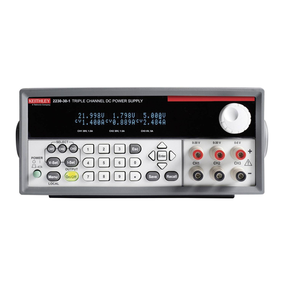
Preface Preface Welcome Thank you for using a Keithley Instruments product. The Series 2200 Multichannel Programmable DC Power Supplies are flexible DC sources designed to power a wide range of applications. The model 2230-30-1 offers three power channels and the model 2220-30-1 provides two channels. The output channels on both models are independent and isolated, allowing you to power circuits with different references or polarities. -
Page 10: Extended Warranty
Extended warranties are available on new and existing products. Contact your local Keithley Instruments representative for details. -
Page 11: Specifications
Specifications This section contains specifications for the Series 2200 Multichannel Programmable DC Power Supplies. All specifications are guaranteed unless noted as "typical." Typical specifications are provided for your convenience but are not guaranteed. Specifications that are marked with the symbol are checked in Performance Verification. - Page 12 Specifications Table 1: Series 2200 specifications (cont.) Parameter Description 1 mA Current resolution, nominal ±(0.1% + 5 mA) at 25 °C ±5 °C Current setting accuracy Voltage limit, 0 to 30 V nominal Current ±(0.1% + 5 mA) per °C outside the 25 °C ±5 °C standard range temperature coefficient, typical Meter, nominal...
- Page 13 Specifications Table 1: Series 2200 specifications (cont.) Parameter Description Voltage transient <150 ms to within 75 mV following a change from 0.1 A to 1 A. response settling time, load change, typical Voltage transient <150 ms from beginning of excursion to within 75 mV of terminal value following a change from 1 V to 11 V response settling into a 10 Ω...
-
Page 14: Table 2: 2230-30-1 And 2230J-30-1 Specifications For Channels 1 And 2
Specifications Table 2: 2230-30-1 and 2230J-30-1 specifications for Channels 1 and 2 (cont.) Parameter Description Remote Sense Voltage Range The total voltage from - terminal to + terminal may not exceed the rated full scale voltage +0.2V, allowing a minimum of 0.1V/line for remote sense. The Maximum voltage difference between a terminal and its associated sense line may not exceed 1V. - Page 15 Specifications Table 2: 2230-30-1 and 2230J-30-1 specifications for Channels 1 and 2 (cont.) Change from 10 to 90% of full scale. Current: ±(0.01% + 3 mA) Load regulation – Current While not readily testable, similar performance is expected over the 0% to 100% of full scale range of the product.
-
Page 16: Table 3: 2230-30-1 And 2230J-30-1 Specific Specifications For Channel 3
Specifications Table 3: 2230-30-1 and 2230J-30-1 specific specifications for Channel 3 (cont.) Constant Current Operation, The unit may be set to be a constant current over a range of voltages. nominal Current Range The output voltage may be adjusted from 0 A to 5 A. Current Resolution, nominal 1 mA +/-(0.1% + 5 mA) at 25 °C ±5 °C. -
Page 17: Table 4: Combined Channel Characteristics
Specifications Table 4: Combined channel characteristics Characteristic Description Combined Channel The unit can be configured to provide functionality on Channel 1 and Channel 2 together. Characteristics, nominal Series Combinations, nominal Deliver up to 60 V when CH1 and CH2 are wired in series. Voltage Readback is the combined voltage. -
Page 18: Table 6: Mains Power Characteristics
Specifications Table 6: Mains power characteristics Characteristic Description The 2220 and the 2230 each have two ranges, selectable with a bottom panel switch. Each Source Voltage range is capable of ±10% excursions. Marked Allowed nominal voltages 110/115/120 VAC 220/230/240 VAC The 2220J-30-1 and the 2230J-30-1 each have two ranges, selectable with a bottom panel switch. -
Page 19: Table 8: Terminal Strip
Specifications Table 7: Common characteristics (cont.) Item Description Isolation Voltage, Output to Any output can be floated up to 240 V (DC + peak AC with AC limited to a maximum 3 V pk-pk Chassis maximum of 60 Hz) relative to the Earth Ground terminal. Note that remote sense terminals should remain within 1 V of their respective outputs to avoid possible damage. -
Page 20: Table 10: Mechanical Characteristics
Specifications Table 10: Mechanical characteristics Parameter Weight, 9 kg instrument, (19.8 lbs) nominal Dimensions, Model Dimensions (Width * Height * Depth nominal 2230 214 mm * 88 mm * 355 mm (8.45” * 3.47” * 13.9”) Cooling method, nominal Required cooling Rear of instrument must be separated by at least 5 cm (2 in) from any airflow restrictions to assure adequate clearance cooling. -
Page 21: Table 13: Safety Characteristics
Specifications Table 13: Safety characteristics Item Description Safety Certifications U.S. Nationally Recognized Testing Laboratory (NRTL) Listing UL61010-1–2004 Safety Requirements for Electrical Equipment for Measurement, Control, and Laboratory Use Canadian Certification CAN/CSA C22.2 No. 61010-1-2004 Safety Requirements for Electrical Equipment for Measurement, Control, and Laboratory Use European Union Compliance Low Voltage Directive 2006/95/EC... -
Page 22: Table 14: Electromagnetic Compatibility (Emc) - Measurement, Laboratory, And Control Product Family
Specifications Table 14: Electromagnetic Compatibility (EMC) — Measurement, laboratory, and control product family Item Description Regional Certifications, Classifications, and Standards List European Union EC Council EMC Directive 2004/108/EC Demonstrated using: EN 61326-1:2006 Electrical Equipment for Measurement, Control, and Laboratory Emissions CISPR 11, Class A Immunity IEC 61000-4-2... - Page 23 Performance Verification This section contains performance verification procedures for the specifications marked with the symbol. Additional test equipment is required to complete the verification procedures. (See Table 27 on page 24.) These procedures cover all models of the Series 2200 Programmable DC Power Supplies.
- Page 24 The performance verification procedures verify the performance of your instrument. They do not adjust your instrument. If your instrument fails any of the performance verification tests, you should contact Keithley service. WARNING. Observe all safety precautions listed in this manual before using this product and any associated instrumentation.
-
Page 25: Test Record
Performance Verification Test Record Model Serial Procedure performed by Date Test Passed Failed Self test DC voltage accuracy with remote sense DC voltage accuracy without remote sense DC voltage readback accuracy DC voltage line regulation DC voltage load regulation DC current accuracy DC current readback accuracy DC current line regulation DC current load regulation... -
Page 26: Table 15: Dc Voltage Accuracy With Remote Sense
Performance Verification Table 15: DC voltage accuracy with remote sense Instrument test voltage DUT voltage Test current Measured Channel 1 __________ 0.00000 V 0.5 A -0.01000 V 0.01000 V __________ 7.5000 V 0.5 A 7.48775 V 7.51225 V __________ 15.00000 V 0.5 A 14.98550 V 15.01450 V... -
Page 27: Table 16: Dc Voltage Accuracy Without Remote Sense
Performance Verification Table 16: DC voltage accuracy without remote sense Instrument test voltage DUT voltage Test current Measured Channel 1 __________ 0.00000 V 0.5 A -0.01000 V 0.01000 V __________ 7.50000 V 0.5 A 7.48625 V 7.51375 V __________ 15.00000 V 0.5 A 14.98250 V 15.01750 V... -
Page 28: Table 17: Dc Voltage Readback Accuracy
Performance Verification Table 17: DC voltage readback accuracy Instrument Measured Voltage Absolute Maximum test voltage DUT voltage Test current voltage readout difference difference Channel 1 ________ ________ ________ 0.00000 V 0.5 A 0.01000 V ________ ________ ________ 7.50000 V 0.5 A 0.01225 V ________ ________... -
Page 29: Table 18: Dc Voltage Line Regulation
Performance Verification Table 18: DC voltage line regulation Instrument Min line Max line Nom line Nom – Min Max – Nom Largest Max value _________ _________ _________ _________ _________ _________ Channel 1 0.0120000 V _________ _________ _________ _________ _________ _________ Channel 2 0.0120000 V _________... -
Page 30: Table 20: Dc Current Accuracy
Performance Verification Table 20: DC current accuracy Instrument test current Test voltage DUT current Measured current Channel 1 __________ 15 V 0.00000000 A -0.00500000 A 0.00500000 A __________ 15 V 0.3750 A 0.36963 A 0.38037 A __________ 15 V 0.75000 A 0.74425 A 0.75575 A __________... -
Page 31: Table 21: Dc Current Readback Accuracy
Performance Verification Table 21: DC current readback accuracy Instrument test Measured Absolute Maximum current Test current current Current readout difference difference Channel 1 ________ ________ ________ 0.00500000 A ________ ________ ________ 0.375 A 0.0053750 A ________ ________ ________ 0.75 A 0.00575000 A ________ ________... -
Page 32: Table 22: Dc Current Line Regulation
Performance Verification Table 22: DC current line regulation Test Nom – Max – Instrument voltage Min line Max line Nom line Largest Max value ______ ______ ______ ______ ______ ______ Channel 1 15 V 0.004500A ______ ______ ______ ______ ______ ______ 15 V 0.004500A... -
Page 33: Performance Verification Procedures
Performance Verification Performance Verification Procedures Performance Verification The following conditions must be met before performing these procedures: Conditions 1. The Device Under Test (DUT) and all test equipment must have been operating continuously for 20 minutes in an environment that meets the operating range specifications for temperature and humidity. -
Page 34: Table 27: Test Equipment
Variable DC Load capable of 6 ADC and 40 VDC B&K Precision 8510 DC voltmeter Voltage measurement at 12 mV through 40 V to better Keithley 2000 DMM than 100 ppm accuracy with the ability to multiply the result by a scalar. High current hook up wire 18 AWG (minimum) hookup wire assemblies. - Page 35 Performance Verification Table 27: Test equipment (cont.) Item Minimum requirements Example 50 mΩ resistor for Remote 0.050 Ω, 5 W. OHMITE 15FR050E Sense testing To perform the tests as illustrated, both leads of each (2 required) resistor require a Banana Jack connector (e.g. Pomona model 4834).
- Page 36 If you need more help, contact Keithley. 8. Power off the DUT. Series 2200 Multichannel Programmable DC Power Supplies Technical Reference...
- Page 37 Performance Verification Check DC Voltage Equipment required Accuracy with Remote (Item 2) AC Power Source (Item 5) High current hook up wire (bold line Sense connections) (Item 3) Electronic Load (Item 6) Low current hook up wire (fine line connections) (Item 4) DC Voltmeter (Item 9) 0.050 Ω, 5 W Resistor (Qty 2) For each of the channels sequentially.
- Page 38 Performance Verification Figure 3: Configuring the shorting clips on a Remote Sense connector to test channel 3 on a 2230-30-1 3. Set up the equipment as shown. (See Figure 4.) NOTE. To assure accurate measurements, it is important that a significant amount of current does not flow through the sense leads.
- Page 39 Performance Verification Figure 4: DC voltage accuracy with remote sense test setup. The channel 1 test setup is shown. Series 2200 Multichannel Programmable DC Power Supplies Technical Reference...
- Page 40 Performance Verification 4. Power on the DUT. NOTE. Ensure the warm-up criteria has been met as described in the Performance Verification Conditions. 5. Set the voltmeter as follows: a. Set to measure DC volts. b. Set to auto range. c. Verify that the Math mx+b function is disabled (shift DCV), assuring that volts are being read.
- Page 41 Performance Verification Check DC Voltage Setting Equipment required Accuracy Without Remote (Item 2) AC Power Source (Item 5) High current hook up wire (bold line Sense and Voltage connections) Readback Accuracy (Item 3) Electronic Load (Item 6) Low current hook up wire (fine line connections) (Item 4) DC Voltmeter For each channel sequentially.
- Page 42 Performance Verification Figure 5: Voltage accuracy, regulation, and protection test setup. The channel 1 test setup is shown. 2. Set the voltmeter as follows: a. Set to measure DC volts. b. Set to auto range. c. Verify that the Math mx+b function is disabled (shift DCV), assuring that volts are being read.
- Page 43 Performance Verification 7. Enter the voltmeter reading into the table for checking DC voltage accuracy without remote sense. (See Table 16 on page 17.) 8. Enter the voltmeter reading into the table for checking DC voltage readback accuracy. (See Table 17 on page 18.) 9.
- Page 44 Performance Verification Check DC Voltage Line This check procedure uses the same test setup as the previous procedure. (See Figure 5.) Regulation For each channel sequentially. 1. Change the AC Power Source output to the minimum voltage specified in the following table.
- Page 45 Performance Verification 7. Enter the voltmeter reading into the table for checking DC Voltage Line Regulation under the min column for the CUT. (See Table 18 on page 19.) Series 2200 Multichannel Programmable DC Power Supplies Technical Reference...
- Page 46 Performance Verification 8. Change the AC Power Source output to the maximum voltage specified in the following table. DUT voltage selector switch AC Power Source voltage Japan configured units 132 V 110 V 264 V 220 V 9. Enter the voltmeter reading into table for checking DC Voltage Line Regulation under the Max column for the CUT.
- Page 47 Performance Verification Check DC Voltage Load This check procedure uses the same test setup as the previous procedure. (See Figure 5.) Regulation For each channel sequentially. NOTE. Ensure the warm-up criteria has been met as described in the Performance Verification Conditions. 1.
- Page 48 Performance Verification 9. Increase the electronic load to the maximum load test current value. Channel Maximum load test current Channel 1 1.47 A Channel 2 1.47 A Channel 3 4.9 A 10. Enter the voltmeter reading into the table for checking DC Voltage Load Regulation under the maximum load column for the channel.
- Page 49 Performance Verification Check DC Current and Equipment required DC Current Readback (Item 2) AC Power Source (Item 5) High current hook up wire (bold line Accuracy connections) (Item 3) Electronic Load (Item 7) High Accuracy 0.05 Ω Resistor (Item 4) DC Voltmeter (Item 8) Current Shunt Resistor Cabling For each channel sequentially.
- Page 50 Performance Verification 2. Set the voltmeter as follows: a. Set to measure DC volts. b. Set to auto range. c. Set to show amps (instead of volts) by multiplying the voltmeter result by 20. Press Shift DC V (mX+B). Use the arrow key to move the cursor to the far right until it is positioned on the ^.
- Page 51 Performance Verification This completes the check for one channel. If needed, return to step 1 to run through the check for the next channel. Series 2200 Multichannel Programmable DC Power Supplies Technical Reference...
- Page 52 Performance Verification Check DC Current Line This check procedure uses the same test setup as the previous procedure.(See Figure 6.) Regulation For each channel sequentially. 1. Change the AC Power Source output to the voltage specified in the following table. DUT voltage selector switch AC power source voltage...
- Page 53 Performance Verification 6. Turn the DUT output on. 7. Enter the voltmeter reading into the table for checking current line regulation under the minimum line for the CUT. (See Table 22 on page 22.) 8. Change the AC Power Source output to the voltage specified in the following table.
- Page 54 Performance Verification Check DC Current Load This check procedure uses the same test setup as the previous procedure. (See Figure 6.) Regulation NOTE. Ensure the warm-up criteria has been met as described in the Performance Verification Conditions. For each channel sequentially. 1.
- Page 55 Performance Verification 6. Enter the voltmeter reading into the table for checking current load regulation at the minimum voltage for your product. (See Table 23 on page 22.) Series 2200 Multichannel Programmable DC Power Supplies Technical Reference...
- Page 56 Performance Verification Increase the electronic load to the Reference test voltage level. Channel under test Reference test voltage Channel 1 15.0 V 15.0 V Channel 2 3.0 V Channel 3 8. Enter the voltmeter reading into the table for checking current load regulation at the reference test voltage the CUT.
- Page 57 Performance Verification Check Voltage Noise Equipment required (7 MHz) (Item 5) High current hook up wire (Item 12) Oscilloscope (bold line connections) (Item 10) Load Resistor (Item 13) Oscilloscope 1X probe For each channel sequentially. 1. Plug the DUT into your local line power from the mains. 2.
- Page 58 Performance Verification Figure 7: 7 MHz test setup. The channel 1 test setup is shown. Series 2200 Multichannel Programmable DC Power Supplies Technical Reference...
- Page 59 Performance Verification 5. Set the oscilloscope as follows: a. 1 mV/division b. 1 MΩ input resistance c. 20 MHz bandwidth (BW) limit d. AC Coupled e. Line trigger 2 ms/div g. Set to measure V and V 6. Set the oscilloscope probe to 1X mode. 7.
- Page 60 Performance Verification Check Voltage Noise Equipment required (20 MHz) (Item 5) High current hook up wire (Item 15) Coaxial cable (BNC M-M) (bold line connections) (Item 10) Load Resistor (Item 16) BNC F-to-Banana (Item 12) Oscilloscope For each channel sequentially. 1.
- Page 61 Performance Verification Figure 8: 20 MHz voltage noise test setup. The channel 1 test setup is shown. Series 2200 Multichannel Programmable DC Power Supplies Technical Reference...
- Page 62 Performance Verification 5. Set the oscilloscope as follows: a. 1 mV/division b. 1 MΩ input resistance c. 20 MHz bandwidth (BW) limit d. AC Coupled e. Line trigger 2 ms/div g. Set to measure V and V 6. Set the channel under test (CUT) to the 100% FS output voltage. 7.
- Page 63 Performance Verification Check Current Noise Equipment required (Item 5) High current hook up wire (Item 12) Oscilloscope (bold line connections) (Item 11) 1 Ω Load Resistor (Item 14) Oscilloscope 10X probe For each channel sequentially. 1. Plug the DUT into your local line power from the mains. 2.
- Page 64 Performance Verification 5. Set the oscilloscope as follows: a. 1 mV/division b. 1 MΩ input resistance c. 20 MHz bandwidth (BW) limit d. AC Coupled e. Line trigger 2 ms/div g. Set to measure V and V 6. Set the channel under test (CUT) to the 100% FS output voltage. 7.
- Page 66 M E A S U R E C O N F I D E N C E Keithley Instruments, Inc. Corporate Headquarters • 28775 Aurora Road • Cleveland, Ohio 44139 • 440-248-0400 • Fax: 440-248-6168 • 1-888-KEITHLEY • www.keithley.com 12/06...
Need help?
Do you have a question about the 2200 Series and is the answer not in the manual?
Questions and answers