
Related Manuals for Keithley 2303


Summary of Contents for Keithley 2303
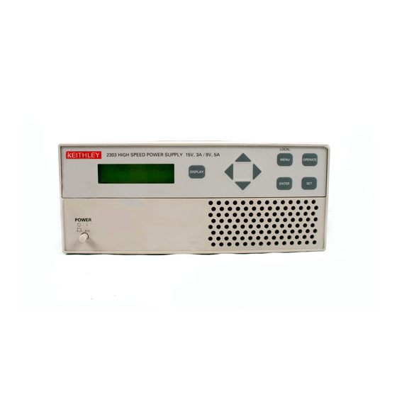
- Page 1 Model 2303/2303B/2303-PJ High Speed Power Supply User’s Manual A G R E A T E R M E A S U R E O F C O N F I D E N C E...
-
Page 2: Limitation Of Warranty
WARRANTY Keithley Instruments, Inc. warrants this product to be free from defects in material and workmanship for a period of 2 years from date of shipment. Keithley Instruments, Inc. warrants the following items for 90 days from the date of shipment: probes, cables, rechargeable batteries, diskettes, and documentation. - Page 3 Model 2303/2303B/2303-PJ High Speed Power Supply User’s Manual ©1998, Keithley Instruments, Inc. All rights reserved. Cleveland, Ohio, U.S.A. Sixth Printing, August 2003 Document Number: 2303-900-01 Rev. F...
- Page 4 Addendum D (Document Number 2303-900-02) ............October 2000 Revision E (Document Number 2303-900-01) ............October 2000 Revision F (Document Number 2303-900-01).............. August 2003 All Keithley product names are trademarks or registered trademarks of Keithley Instruments, Inc. Other brand names are trademarks or registered trademarks of their respective holders.
- Page 5 Keithley products are designed for use with electrical signals that are rated Measurement Category I and Measurement Category II, as described in the International Electrotechnical Commission (IEC) Standard IEC 60664. Most measurement, control, and data I/O signals are Measurement Category I and must not be directly connected to mains voltage or to voltage sources with high transient over-voltages.
- Page 6 To maintain protection from electric shock and fire, replacement components in mains circuits, including the power transformer, test leads, and input jacks, must be purchased from Keithley Instruments. Standard fuses, with applicable national safety ap- provals, may be used if the rating and type are the same. Other components that are not safety related may be purchased from other suppliers as long as they are equivalent to the original component.
-
Page 7: Table Of Contents
Table of Contents 1 Getting Started General information ................1-2 Warranty information............... 1-2 Contact information ............... 1-2 Safety symbols and terms .............. 1-2 Specifications ................. 1-2 Inspection ..................1-3 Options and accessories ..............1-3 Power supply overview ..............1-4 Remote display option ............... 1-6 Power-up .................... - Page 8 3 Pulse Current Measurements Overview .................... 3-2 Trigger level ................... 3-3 Trigger delay .................. 3-3 Integration times ................3-3 Average readings count ..............3-3 Measurement configuration ............... 3-4 Current range .................. 3-4 Integration times ................3-4 Average readings count ..............3-5 Trigger delay and trigger level ............
- Page 9 5 Relay Control Overview ................... 5-2 Connections ..................5-4 Controlling the relay ................5-5 SCPI programming ................ 5-5 6 GPIB Operation Introduction ..................6-2 GPIB bus connections ............... 6-2 Primary address ................. 6-3 Output format ..................6-3 General bus commands ..............6-4 REN (remote enable) ..............
- Page 10 Status register sets ................7-10 Register bit descriptions ............... 7-10 Condition registers ............... 7-15 Event registers ................7-15 Event enable registers ..............7-16 Programming example — program and read measurement event register ............ 7-17 Queues ..................... 7-17 Output queue ................7-17 Error queue ...................
- Page 11 10 DISPlay, FORMat, and SYSTem DISPlay subsystem ................10-2 :DISPlay:ENABle <b> ..............10-2 :DISPlay:TEXT:DATA <a> ............10-2 :DISPlay:TEXT:STATe <b> ............10-3 FORMat subsystem ................. 10-4 FORMat[:DATA] <type> ............. 10-4 FORMat:BORDer <name> ............10-6 :SYSTem subsystem ................ 10-7 :SYSTem:POSetup <name> ............10-7 11 SCPI Tables SCPI command subsystems reference tables ........
- Page 12 List of Illustrations 1 Getting Started High speed power supply ..............1-4 Simplified power supply diagram ............1-5 2 Basic Power Supply Operation Typical connections ................2-2 Output capabilities ................2-3 Sink operation example ..............2-12 3 Pulse Current Measurements Pulse current measurement ..............
- Page 13 List of Tables 1 Getting Started Factory defaults (RST) ..............1-9 MENU structure ................1-12 2 Basic Power Supply Operation Current ranges..................2-4 SCPI commands — outputting voltage and current ......2-7 SCPI commands — measure V and I, and DVM input ....2-10 Sink current limits ................
- Page 14 SENSe command summary ............. 11-4 SOURce command summary ............11-6 STATus command summary ............11-7 SYSTem command summary ............11-8 C Emulation Commands HP commands used to control the power supply ......C-2 Fluke commands used to control Model 2303/2303B/2303-PJ ..C-5...
-
Page 15: Getting Started
Getting Started • General information — Covers general information that includes warranty informa- tion, contact information, safety symbols and terms, inspection and available options and accessories. • Power supply overview — Summarizes the capabilities of the power supply. • Remote display option — Explains how to use the optional Model 2304-DISP Display Module. -
Page 16: General Information
Applications Engineers at 1-800-3735 (U.S. and Canada only). Worldwide phone numbers are listed at the front of this manual. Safety symbols and terms Keithley uses a standard set of safety symbols and terms that may be found on an instrument or in its manual. If a screw is present, connect it to safety earth ground using the wire recommended in the user documentation. -
Page 17: Inspection
Report any damage to the shipping agent immediately. Save the original packing carton for possible future shipment. The following items are included with every order: • Model 2303/2303B/2303-PJ High Speed Power Supply with line cord • Quick Disconnect Output/DVM Input Connector •... -
Page 18: Power Supply Overview
Model 2303B has a blank front panel except for a POWER switch and an ON/OFF LED. All references to front panel messages, menus, and keystrokes apply to the Models 2303 and 2303-PJ, and the 2303B if using the Model 2304-DISP remote display module. -
Page 19: Getting Started
Current Readback Ranges: • Models 2303 and 2303B – Two ranges for current readback: 5A and 5mA. On the 5A range, display resolution is 100µA, and on the 5mA range, resolution is 0.1µA. • Model 2303-PJ – Two ranges for current readback: 5A and 500mA. On the 5A range, display resolution is 100µA, and on the 500mA range, resolution is 0.01mA (10µA). -
Page 20: Remote Display Option
NOTE When the remote display is attached to a Model 2303B, the power supply acts like a Model 2303. The remote display module plugs into the rear panel connector labeled “REMOTE DISPLAY OPTION” (see Figure 1-1B). When plugged in, the main display module is disabled with the... -
Page 21: Fuse Replacement
On power-up, the power supply performs self-tests on its EPROM and RAM. NOTE If a problem develops while the instrument is under warranty, return it to Keithley Instruments Inc., for repair. If the instrument passes the self-tests, the following information is briefly displayed: Top line —... -
Page 22: Display Modes
Getting Started Display modes For voltage and current readings, there are four display modes described as follows: • ACTUAL V AND I — This display mode is used to read back the actual output voltage and current. This display mode is the RST default. (See Section 2 for details.) •... -
Page 23: Default Settings
Output state operate Display type Actual V and I GPIB address No effect (factory set to 16) GPIB output format No effect (factory set to Keithley and Exponential) Current range 5 amps (Auto Range off) Integration rate 1.00 PLC Average readings... -
Page 24: Setups - Save, Power-On, And Recall
Table 1-1 (cont.) Factory defaults (RST) Setting RST default Average time 33 µsec Average readings Trigger delay 0.00000 sec Trigger level: Models 2303 and 2303B 0.000A Model 2303-PJ: 5A range 0.000A 500mA range 0.0000A Long integration: Integration time 1 second... -
Page 25: Menu
Getting Started 1-11 If you want the Model 2303 or 2303B to power up with the output on, you must use SAV5, SAV6, SAV7, SAV8, or SAV9 as the power-on setup. For the SAV5 power-on setup, the power supply will power up to the SAV0 settings, and the output will be on or off depending on the output state when the setup was saved as SAV0. -
Page 26: Menu Structure
Reply with Fluke information to *IDN? Current range Select current range: Sec 2 Models 2303 and 2303B – 5A, 5mA or AUTO. Model 2303-PJ – 5A, 500mA or AUTO Integration rate Set integration rate in NPLC (0.01 to 10). Sec 2 Average readings Set average reading count (1 to 10). -
Page 27: Rules To Navigate Menu
Getting Started 1-13 Rules to navigate MENU • The MENU is accessed by pressing the MENU key. • Use the edit keys to display the primary menu items. • A displayed primary menu item is selected by pressing ENTER. With PULSE CUR- RENT or LONG INTEGRATION selected, use the edit keys to display the sec- ondary items and press ENTER to select the displayed item. - Page 28 1-14 Getting Started...
-
Page 29: Basic Power Supply Operation
Basic Power Supply Operation • Test connections — Explains how to connect the device under test (DUT) to the power supply output, and how to connect an external voltage to the DVM input. • Outputting voltage and current — Explains how to output voltage and current. •... -
Page 30: Test Connections
Test connections to the power supply are made at the rear panel using a quick disconnect OUTPUT/DVM IN connector (Keithley part number CS-846). Figure 1-1B shows where the connector plugs in. Use up to #14 AWG wire for the screw terminals of the connector. Once the connector is wired up, plug it into the rear panel and tighten the captive retaining screws. -
Page 31: Outputting Voltage And Current
9V, the maximum current limit is 3A. Figure 2-2 Output capabilities I-Limit V-Source A) 5A or AUTO Measurement Range I-Limit V-Source B) 5mA Measurement Range (Models 2303 and 2303B) I-Limit 0.6A V-Source C) 500mA Measurement Range (Model 2303-PJ) -
Page 32: Current Ranges
5 milliamps range will be the same when switching from the 5A range to the 5 milliamps range. Model 2303-PJ – Selecting the 500 milliamps range defaults the current limit setting to 0.6A since that is the maximum allowable setting on that range. Toggling back to the 5 amps range reinstates the 3A limit. - Page 33 Goes off Tracks current limit state. * LIMIT RELAY and TRIP RELAY available in Models 2303 and 2303B with firmware revision level A06 and higher. LIM mode - With the lim mode selected, the output will remain on when the current limit is reached.
-
Page 34: Relay Control
Basic Power Supply Operation NOTE When the current limit relay control mode is selected, the relay may chatter or not have sufficient time to pull in if the current value is fluctuating around the set cur- rent limit, depending on how rapidly the current is fluctuating around the current limit point. - Page 35 Basic Power Supply Operation Current limit mode selection - The current limit mode is selected from the current lim mode item of the menu. The menu is accessed by pressing the MENU key. NOTE Table 1-2 (in Section 1) shows the menu structure. Rules to navigate the menu follow the table.
-
Page 36: Operate
LIMRELAY (LIMITRELAY), or TRIPRELAY. * :STATe? Query state of current limit. OUTPut OUTPut subsystem: [:STATe] <b> Turn the power supply output on or off. * LIMRELAY (LIMITRELAY) and TRIPRELAY available in Models 2303/2303B with firmware revision level A06 and higher. - Page 37 1. 5A or AUTO measurement range selected - With output voltage set to ≤9V, the maxi- mum current limit value is 5A. With voltage set to >9V, the maximum current limit is 2. Models 2303 and 2303B: • With the 5mA measurement range selected, the maximum current limit is 1A.
- Page 38 2-10 Basic Power Supply Operation CURRent:TYPe <name> Parameters are summarized in Table 2-4 and described as follows: 1. With the LIMit type selected, the output will remain on when the current limit is reached. 2. With the TRIP mode selected, the output will turn off when the current limit is reached. 3.
-
Page 39: Reading Back V And I
Basic Power Supply Operation 2-11 Reading back V and I Actual V and I display mode Measured output voltages and currents are displayed with the actual V and I display mode selected. This display mode is selected as follows: NOTE If output settings are presently being displayed (as denoted by a blinking digit in the voltage or current field), keep pressing the SET key until the blinking stops. -
Page 40: Scpi Programming - Measure V And I, And Dvm Input
2-12 Basic Power Supply Operation Average readings The average reading count (1 to 10) specifies the number of measurement conversions to average for each reading. For example, with a reading count of 5, each displayed reading will be the average of five measurement conversions. The AVERAGE READINGS item of the menu is also used to set the average reading count for DVM measurements. -
Page 41: Independent Voltage Measurements (Dvm)
Basic Power Supply Operation 2-13 2. When requesting an array of readings (FETCh:ARRay?, READ:ARRay? or MEASure:ARRay?), average count specifies the number of measurements to place in an array. For example, with the average count set to 10, READ:ARRay? will trigger and return 10 readings. -
Page 42: Sink Operation
2-14 Basic Power Supply Operation Sink operation Whenever a test circuit sources a voltage that exceeds the programmed supply voltage, the power supply automatically becomes a sink instead of a source. It then dissipates power instead of supplying power, while continuing to maintain the programmed supply voltage at its termi- nals. -
Page 43: Programming Examples
Basic Power Supply Operation 2-15 Programming examples Outputting and reading back V and I The following command sequence demonstrates how to output voltage and current, and read back (measure) the actual voltage and current: VOLT 5 ‘ Set output voltage to 5V. SENS:CURR:RANG:AUTO ON ‘... - Page 44 2-16 Basic Power Supply Operation...
-
Page 45: Pulse Current Measurements
Pulse Current Measurements • Overview — Provides an overview of the pulse current measurement process. • Measurement configuration — Explains how to configure the instrument for pulse cur- rent measurements. • Pulse current measurement procedure — Provides the step-by-step procedure to per- form pulse current measurements from the front panel. -
Page 46: Overview
NOTE For Models 2303 and 2303B, pulse-measurements are automatically performed on the 5A range. For Model 2303-PJ, pulse-current measurements can be performed on either the 5A range or 500mA range. The high, low, and average measurements of a pulse are illustrated in Figure 3-1. The high measurement is triggered on the rising edge of the pulse, and an integration is performed for the time specified for the high measurement. -
Page 47: Trigger Level
For Models 2303 and 2303B, the maximum trigger level is 5A. For Model 2303-PJ, the trigger level can be set for each measurement range. For the 5A range the maximum trigger level is 5A, and for the 500mA range, the maximum trigger level is 500mA. -
Page 48: Measurement Configuration
For pulse current measurements, the AUTO range selection is functionally a no-op (no oper- ation). The instrument will not autorange with the pulse current measurement function selected. For Models 2303 and 2303B, pulse current measurements are performed on the 5A range, regardless of the range selection. -
Page 49: Average Readings Count
TRIGGER LEVEL — Use to set the trigger level. Pulses less than the specified level are not detected. Models 2303 and 2303B – Set the trigger level from 0 to 5A in 5mA steps. However, there is approximately 10mA of trigger hysteresis built into the hardware. Therefore, if a pulse does not exceed this level, trigger detection will not occur. -
Page 50: Pulse Current Measurement Procedure
Determining correct trigger level (pulse current) If using Model 2303-PJ, make sure it is on the same current range (5A or 500mA) that is being used for pulse measurements (step 1 of the “Pulse current measurement procedure”). -
Page 51: Scpi Programming
Pulse detection triggering: [:STATe] Send ON to select pulse current measurements. OFF selects pulse current digitization. :TLEVel <NRf> Models 2303 and 2303B - Set trigger level in amps; 0 to 5. :TLEVel Model 2303-PJ trigger level: [:AMPs] <NRf> Set trigger level (in amps) for 5A range; 0 to 5. - Page 52 Pulse Current Measurements A. SENSe:FUNCtion ‘PCURrent’ The parameter name can instead be enclosed in single quotes (as shown above). B. SENSe:PCURrent:AVERage <NRf> 1. When requesting a single reading (FETch?, READ?, or MEASure?), average count specifies the number of pulse current measurement conversions to average for the read- ing.
-
Page 53: Pulse Current Digitization
Pulse Current Measurements Pulse current digitization The following discussion explains how to digitize a current waveform. A programming example at the end of this section demonstrates proper command sequence for pulse current digitization. With pulse current digitization selected, readings are taken at a constant integration time of 33µsec across the pulse or pulse train. -
Page 54: Programming Examples
3-10 Pulse Current Measurements Programming examples Pulse current measurements The following command sequence will return the average of 10 peak pulse current measurements: SENS:RANG 5 ‘ Select 5A range. VOLT 15 ‘ Set output voltage to 15V. CURR 0.75 ‘ Set current limit to 750mA. OUTP ON ‘... -
Page 55: Long Integration Measurements
Long Integration Measurements • Overview — Provides an overview of the long integration measurement process. • Measurement configuration — Explains how to configure the instrument for long inte- gration measurements. • Long integration measurement procedure — Provides the step-by-step procedure to perform long integration measurements from the front panel. -
Page 56: Overview
NOTE For Models 2303 and 2303B, long integration current measurements are automatical- ly performed on the 5A range. For Model 2303-PJ, pulse current measurements can be performed on either the 5A range or 500mA range. Long integration measurement is accomplished by taking an integral number of integration cycles during the total measurement time. -
Page 57: Integration Time
2A, pulses that are (≥2A will be detected. Current pulses <2A are ignored. For Models 2303 and 2303B, the maximum trigger level is 5A. For Model 2303-PJ, the trig- ger level can be set for each measurement range. For the 5A range the maximum trigger level is... -
Page 58: Pulse Timeout
For long integration measurements, the AUTO range selection is functionally a no-op (no oper- ation). The instrument will not autorange with the long integration measurement function selected. For Models 2303 and 2303B, long integration measurements are performed on the 5A range, regardless of the range selection. -
Page 59: Integration Time
Models 2303 and 2303B – Set the trigger level from 0 to 5A in 5mA steps. Models 2303-PJ – The trigger level can be set for either the 5A or 500mA range. For the 5A range, the trigger level can be set from 0 to 5A in 5mA steps. For the 500mA range, the trigger... -
Page 60: Long Integration Display Mode
Long integration measurement procedure The following steps summarize the procedure to perform long integration current measurements: For Model 2303-PJ, select the desired measurement range (5A or 500mA) from the CURRENT RANGE item of the menu. For Models 2303 and 2303B, long integration measurements are automatically performed on the 5A range. -
Page 61: General Notes
Determining correct trigger level (long integration) If using Model 2303-PJ, make sure it is on the same current range (5A or 500mA) that is being used for long integration measurements (step 1 of the “pulse current measure- ment procedure”). -
Page 62: Scpi Programming
Set integration time (in sec); X to 60 (where X is 0.850 for 60Hz, or 0.840 for 50Hz). :AUTO Integration time set automatically. :TLEVel <NRf> Models 2303 and 2303B - Set trigger level in amps; 0 to 5 (5mA resolution. :TLEVel Model 2303-PJ trigger level: [:AMPs] <NRf>... -
Page 63: Programming Example
Long Integration Measurements C. SENSe:LINTegration:SEARch <b> Boolean Parameters: • OFF or 0 - The search will stop after the first timeout period expires. The search can be restarted by enabling the search, or by sending a trigger reading command (such as READ?). -
Page 64: Long Integration Measurements
4-10 Long Integration Measurements... -
Page 65: Relay Control
Relay Control • Overview — Summarizes how the power supply can be used to control an external relay. • Connections — Explains how to connect an external relay circuit to the power supply. • Controlling the relay — Explains how to control the external relay circuit. -
Page 66: Overview
Relay Control Overview The power supply can be used to control an external relay. The control circuit is made up of an open-collector transistor that functions as a switch for the external relay, a +5VDC source (100mADC maximum), and a chassis ground return. The drive for the relay may be provided by the supplied +5VDC source or an external DC voltage source. -
Page 67: Relay Control
Relay Control Figure 5-1 Relay control External Source Power Supply Relay Relay Relay Control 15VDC Protection Diode Chassis Ground A. External Source Power Supply Relay +5VDC Control Relay Relay Internal Source +5VDC ±5% Protection Diode Chassis Ground B. Internal Source... -
Page 68: Connections
Relay Control Connections An external relay circuit is connected to the power supply via the miniature phono jack on the rear panel (labeled relay control 15VDC MAX). The required phono plug that mates to the phono jack is shown in Figure 5-2. The illustration provides terminal identification for the conductors of the plug. This phone plug is available from Switchcraft, Inc. -
Page 69: Controlling The Relay
Relay Control Controlling the relay The external relay is controlled from the OUTPUT RELAY item of the menu. The menu is accessed by pressing the MENU key. NOTE Table 1-2 (in Section 1) shows the menu structure. Rules to navigate the menu follow the table. -
Page 70: Relay Control
Relay Control... -
Page 71: Gpib Operation
GPIB Operation • Introduction — Describes the IEEE-488 (GPIB) standards used by the power supply. • GPIB bus connections — Shows how to connect the power supply to the GPIB. • Primary address — Explains how to check and/or change the primary address for the bus. •... -
Page 72: Introduction
NOTE To minimize interference caused by electromagnetic radiation, use only shielded IEEE- 488 cables. Available shielded cables from Keithley are Models 7007-1 and 7007-2. For a multi-unit test system, you can daisy-chain the instruments to the controller by connect- ing an IEEE cable from one unit to another. -
Page 73: Primary Address
10.00 (2 decimal places), 10.000 (3 decimal places) or 10.0000 (4 decimal places). The output type (KEITHLEY or FLUKE) can be set for the response to the *IDN? query command. *IDN? provides identification information. See Section 8 for details on the responses... -
Page 74: General Bus Commands
GPIB Operation General bus commands General bus commands are those commands, such as DCL, that have the same general mean- ing regardless of the instrument. Table 6-1 lists the general bus commands. Table 6-1 General bus commands Command Effect on power supply Goes into remote when next addressed to listen. -
Page 75: Llo (Local Lockout)
GPIB Operation LLO (local lockout) Use the LLO command to prevent local operation of the instrument. After the unit receives LLO, all its front panel controls except POWER are inoperative. In this state, pressing the LOCAL key will not restore control to the front panel. The GTL command restores control to the front panel. -
Page 76: Front Panel Aspects Of Gpib Operation
GPIB Operation Front panel aspects of GPIB operation The following paragraphs describe aspects of the front panel and remote panel that are part of GPIB operation, including the remote operation indicator, LOCAL key, and messages. Remote indicator and LOCAL key When the power supply is in the remote state, the “R”... -
Page 77: Programming Syntax
GPIB Operation Programming syntax The information in the following paragraphs covers syntax for both common commands and SCPI commands. For information not covered here, see the IEEE-488.2 and SCPI standards. Command words Program messages are made up of one or more command words and parameters. Commands and command parameters Common commands and SCPI commands may or may not use a parameter. - Page 78 GPIB Operation • <NRf> Numeric representation format — This parameter is a number that can be expressed as an integer (e.g., 8), a real number (e.g., 23.6), or an exponent (2.3E6). Example: SENSe:AVERage 5 Set average count value to 5 •...
- Page 79 GPIB Operation Case sensitivity Common commands and SCPI commands are not case sensitive. You can use upper or lower case and any case combination. Examples: *RST = *rst :DATA? = :data? :STATus:PRESet = :status:preset Long-form and short-form versions A SCPI command word can be sent in its long-form or short-form version. The command subsystem tables in Section 4 provide the long-form version.
-
Page 80: Program Messages
6-10 GPIB Operation Program messages A program message is made up of one or more command words sent by the computer to the instrument. Each common command is a three letter acronym preceded by an asterisk (*). SCPI commands are categorized in the :STATus subsystem and are used to help explain how command words are structured to formulate program messages. - Page 81 GPIB Operation 6-11 Command path rules • Each new program message must begin with the root command, unless it is optional (e.g., [:SOURce]). If the root is optional, treat a command word on the next level as the root. • The colon (:) at the beginning of a program message is optional and need not be used.
-
Page 82: Response Messages
6-12 GPIB Operation Response messages A response message is the message sent by the instrument to the computer in response to a query command program message. Sending a response message After sending a query command, the response message is placed in the output queue. When the power supply is then addressed to talk, the response message is sent from the output queue to the computer. -
Page 83: Status Structure
Status Structure • Overview — Provides an operational overview of the status structure for the power supply. • Clearing registers and queues — Covers the actions that clear (reset) registers and queues. • Programming and reading registers — Explains how to program enable registers and read any register in the status structure. -
Page 84: Overview
Status Structure Overview The power supply provides a series of status registers and queues allowing the operator to mon- itor and manipulate the various instrument events. The status structure is shown in Figure 7-1. The heart of the status structure is the status byte register. This register can be read by the users test pro- gram to determine if a service request (SRQ) has occurred, and what event caused it. -
Page 85: Status Model Structure
Status Structure 7-3 Figure 7-1 Status model structure Questionable Event Registers Event Condition Event Enable Register Register Register & & & & & & & Logical & & Calibration Summary & & & Error Queue & & & & (Always Zero) :CONDition? [:EVENt]? :ENABle <NRf>... -
Page 86: Clearing Registers And Queues
Status Structure Clearing registers and queues When the power supply is turned on, the bits of all registers in the status structure are clear (reset to 0) and the two queues are empty. Commands to reset the event and event enable registers, and the error queue are listed in Table 7-1. -
Page 87: Programming And Reading Registers
Status Structure 7-5 Programming and reading registers Programming enable registers The only registers that can be programmed by the user are the enable registers. All other reg- isters in the status structure are read-only registers. The following explains how to ascertain the parameter value for the various commands used to program enable registers. -
Page 88: Status Byte And Service Request (Srq)
Status Structure Status byte and service request (SRQ) Service request is controlled by two 8-bit registers; the status byte register and the service request enable register. Figure 7-3 shows the structure of these registers. Figure 7-3 Status byte and service request Status Summary Messages (6) Service Status Byte... -
Page 89: Status Byte Register
Status Structure 7-7 Status byte register The summary messages from the status registers and queues are used to set or clear the appro- priate bits (B0, B2, B3, B4, B5, and B7) of the status byte register. These summary bits do not latch, and their states (0 or 1) are solely dependent on the summary messages (0 or 1). -
Page 90: Serial Polling And Srq
Status Structure The individual bits of the service request enable register can be set or cleared by using the *SRE common command. To read the service request enable register, use the *SRE? query com- mand. The service request enable register clears when power is cycled or a parameter value of 0 is sent with the *SRE command (i.e. -
Page 91: Status Byte And Service Request Commands
Status Structure 7-9 Status byte and service request commands The commands to program and read the status byte register and service request enable regis- ter are listed in Table 7-2. For details on programming and reading registers, see “Programming enable registers” and “Reading registers”. NOTE To reset the bits of the service request enable register to 0, use 0 as the parameter value for the *SRE command (i.e. -
Page 92: Status Register Sets
7-10 Status Structure Status register sets As shown in Figure 7-1, there are four status register sets in the status structure of the power supply: standard event status, operation event status, measurement event status and questionable event status. Register bit descriptions Standard event status The used bits of the standard event register (shown in Figure 7-4) are described as follows: •... -
Page 93: Standard Event Status
Status Structure 7-11 Figure 7-4 Standard event status Standard Event *ESR? (B15 - B8) Register (B2) (B1) (B7) (B6) (B5) (B4) (B3) (B0) & & & To ESB bit & of Status Byte Register & & & *ESE <NRf> Standard Event *ESE? (B15 - B8) (B2) (B1) -
Page 94: Operation Event Status
7-12 Status Structure Operation event status The used bits of the operation event register (shown in Figure 7-5) are described as follows: • Bit B3, current limit (CL) — Set bit indicates that the output is in current limit. This bit clears when the instrument is no longer in current limit. -
Page 95: Measurement Event Status
Status Structure 7-13 Measurement event status The used bits of the measurement event register (shown in Figure 7-6) are described as follows: • Bit B3, reading overflow (ROF) — Set bit indicates that voltage or current reading exceeds the measurement range of the instrument. •... -
Page 96: Questionable Event Status
7-14 Status Structure Questionable event status The used bit of the questionable event register (shown in Figure 7-7) is described as follows: • Bit B8, calibration summary (Cal) — Set bit indicates that an invalid calibration con- stant was detected during the power-up sequence. This error will clear after successful calibration of the power supply. -
Page 97: Condition Registers
Status Structure 7-15 Condition registers As Figure 7-1 shows, each status register set (except the standard event register set) has a con- dition register. A condition register is a real-time, read-only register that constantly updates to reflect the present operating conditions of the instrument. For example, when a current pulse is not detected, bit B4 (PTT) of the measurement condition register will be set (1). -
Page 98: Event Enable Registers
7-16 Status Structure Event enable registers As Figure 7-1 shows, each status register set has an enable register. Each event register bit is logically ANDed (&) to a corresponding enable bit of an enable register. Therefore, when an event bit is set and the corresponding enable bit is set (as programmed by the user), the output (summary) of the register will set to 1, which in turn sets the summary bit of the status byte register. -
Page 99: Programming Example - Program And Read Measurement Event Register
Status Structure 7-17 Programming example — program and read measurement event register The following command sequence enables the buffer full bit (B9) of the measurement register set, and then reads the event register. After the programmed number of readings (average count) have been taken, reading the event register will return a value of 512. -
Page 100: Error Queue
“0, No Error” is placed in the queue. Messages in the error queue are preceded by a code number. Negative (-) numbers are used for SCPI defined messages, and positive (+) numbers are used for Keithley defined messages. The messages are listed in Appendix B. -
Page 101: Scpi Commands - Error Queue
2. Power-up enables error messages and disables status messages. *CLS and STATus:PRESet have no effect. Programming example — read error queue STAT:QUE:ENAB (+000:+900) ‘ Enable all Keithley defined messages (dis- able all SCPI defined messages). STAT:QUE? ‘ Return oldest message. - Page 102 7-20 Status Structure...
-
Page 103: Common Commands
Common Commands... -
Page 104: Overview
Common Commands Overview Common commands are device commands that are common to all devices on the bus. These commands are designated and defined by the IEEE-488.2 standard. Common commands are listed in Table 8-1. Note that detailed information on the Common Commands to program and read status registers is provided in Section 7. -
Page 105: Idn? - Identification Query
The identification code includes the manufacturer, model number, serial number, and firm- ware revision levels. Identification codes vary with the model number, output formats and output types. Power supplies set for the exponential output format and Keithley output types have the following codes: KEITHLEY INSTRUMENTS INC., MODEL 2303, xxxxxxx, yyyyy/zzzzz... -
Page 106: Sav
Common Commands Table 8-2 *OPC and *OPC? commands *OPC *OPC? Comment VOLTage?; *OPC SENSe:NPLC?; *OPC? Valid VOLTage? SENSe:NPLC? Not valid — query interrupted error *OPC *OPC? CURRent 1; *OPC SENSe:NPLC 5; *OPC? Valid CURRent 1 SENSe:NPLC 5 Valid *OPC *OPC? *SAV <NRf>...- Save -
Page 107: Tst? - Self-Test Query
Common Commands *TST? — self-test query Run self test and read result Use this query command to perform a checksum test on ROM. The command places the cod- ed result (0 or 1) in the output queue. When the power supply is addressed to talk, the coded result is sent from the output queue to the computer. -
Page 108: Common Commands
Common Commands... -
Page 109: Signal Oriented Measurement Commands
Signal Oriented Measurement Commands... -
Page 110: Overview
Signal Oriented Measurement Commands Overview The signal oriented measurement commands are used to acquire readings. You can use these high-level instructions to control the measurement process. These commands are summarized in Table 9-1. Table 9-1 Signal oriented measurement command summary Command Description :FETCh? -
Page 111: Read
Signal Oriented Measurement Commands NOTES 1. A FETCh? reading can be returned in exponent form (i.e. 10V returned as +1.00000000E+01) or as a decimal reading (i.e. 10V returned as 10.0000, 10.000 or 10.00). The reading format is selected from the GPIB MENU, OUTPUT FORMAT item of the menu (see “Output Format”... -
Page 112: Measure[:
Signal Oriented Measurement Commands :MEASure[:<function>]? Execute :READ? on specified function :MEASure:ARRay[:<function>]? Execute :READ:ARRay? on specified function Parameters <function> = CURRent[:DC] Measure current VOLTage[:DC] Measure voltage PCURrent Measure pulse-current DVMeter Measure DVM input LINTegration Perform long integration current measurements. When the MEASure? command is sent, the specified function is selected and then the READ? is executed.] -
Page 113: Display, Format, And System
DISPlay, FORMat, and SYSTem • DISPlay subsystem — Covers the SCPI commands that are used to control the display. • FORMat subsystem — Covers the SCPI commands to configure the format that read- ings are sent over the bus. • SYSTem subsystem —... -
Page 114: Display Subsystem
10-2 DISPlay, FORMat, and SYSTem DISPlay subsystem The display subsystem controls the display of the power supply and is summarized in Table 10-1. This subsystem also applies to Model 2303B if using Model 2304-DISP remote display module. Table 10-1 SCPI commands — display Command Description Default... -
Page 115: Display:text:state
DISPlay, FORMat, and SYSTem 10-3 An indefinite block message must be the only command in the program message or the last command in the program message. If you include a command after an indefinite block message (on the same line), it will be treated as part of the message and is displayed instead of executed. Use the next command to enable the text message mode. -
Page 116: Format Subsystem
10-4 DISPlay, FORMat, and SYSTem FORMat subsystem The commands for this subsystem are used to select the data format for transferring instru- ment readings over the bus. These commands are summarized in Table 11-2. NOTE The FORMat commands are only used if the exponential GPIB output format is se- lected. -
Page 117: Display, Format, And System
DISPlay, FORMat, and SYSTem 10-5 ASCII # sign and 0. Not shown in Figure 10-1 is a byte for the terminator that is attached to the end of each data string. Figure 10-1 IEEE-754 single precision data format Header Byte 1 Byte 2 Byte 3 Byte 4... -
Page 118: Format:border
10-6 DISPlay, FORMat, and SYSTem Figure 10-2 IEEE-754 double precision data format Header Byte 1 Byte 2 Byte 7 Byte 8 Bytes 3, 4, 5, and 6 not shown. s = sign bit (0 = positive, 1 = negative) e = exponent bits (11) f = fraction bits (52) Normal byte order shown. -
Page 119: System Subsystem
Power-up to SAV1 (output on or off) SAV7 Power-up to SAV2 (output on or off) SAV8 Power-up to SAV3 (output on or off) SAV9 Power-up to SAV4 (output on or off) NOTE SAV5-SAV9 are not available for the Model 2303-PJ. - Page 120 *SAV command (Section 8). Note that the instrument will power up with the output off. For the Models 2303 and 2303B, the SAV5-9 parameters can be used to power-up the power supply with the output on. It will assume the corresponding SAV0-4 setup, including the saved state of the output.
-
Page 121: Scpi Tables
SCPI Tables... -
Page 122: Scpi Command Subsystems Reference Tables
11-2 SCPI Tables SCPI command subsystems reference tables Tables 11-1 to 11-7 summarize the commands for each SCPI subsystem. The following list in- cludes the SCPI subsystem commands and the table number where each command is summarized. • Table 11-1 DISPlay command summary •... -
Page 123: Display Command Summary
SCPI Tables 11-3 Table 11-1 DISPlay command summary Default Command Description parameter SCPI :DISPlay √ :ENABle <b> Enable or disable front panel display. (Note 1) √ :ENABle? Query state of display. √ [:WINDow[1]] Path to locate message to display: √ :TEXT Control user text message: (Note 2) -
Page 124: Sense Command Summary
[:STATe]? Query pulse current synchronization selection. :DELay <NRf> Specify trigger delay in seconds; 0 to 0.1 or 0 to 5 (pulse current digitization). :DELay? Query trigger delay. :TLEVel <NRf> Models 2303 and 2303B— Set trigger level: 0 to 5 (amps). - Page 125 (where X is 0.850 for 60Hz or 0.840 for 50Hz). :TIME? Query integration time. :AUTO Power supply sets integration time. :TLEVel <NRf> Models 2303 and 2303B - Set trigger level: 0 to 5A. :TLEVel? Models 2303 and 2303B - Query trigger level. :TLEVel Model 2303-PJ: [:AMP] <NRf>...
-
Page 126: Source Command Summary
Query state of current limit: 1 = in current limit (for :STATe? LIMit type) or output tripped (for TRIP type); 0= not in LIMit/TRIP. *LIMRELAY (LIMIT RELAY) and TRIPRELAY are available in Models 2303/2303B with firmware revision A06 and higher. -
Page 127: Status Command Summary
SCPI Tables 11-7 Table 11-6 STATus command summary Default SCPI Command Description parameter √ :STATus (Note 1) :MEASurement Path to control the measurement event registers: [:EVENt]? Read the event register. (Note 2) :ENABle <NRf> Program the enable register. (Note 3) :ENABle? Read the enable register. -
Page 128: System Command Summary
Read and clear oldest message in error queue. :CLEar Clears error queue. :LFRequnecy? Query power line frequency setting. :POSetup <name> Select power-on setup: RST or SAVx, where: x = 0 to 4Model 2303-PJ x = 0 to 9Model 2303/2303B :POSetup? Query power-on setup. - Page 129 Specifications...
- Page 130 :5A range: ±(0.2% + 400µA). 500mA range:±(0.2% + 40µA). READBACK RESOLUTION 2303: 5A range: 100µA. 5mA range: 0.1µA. 2303-PJ: 5A range: 100µA. 500mA range:10µA. CURRENT SINK CAPACITY: 0–5V: 2A max. 5V–15V: Derate 0.1A per volt above 5V. LOAD REGULATION: 0.01% + 1mA. LINE REGULATION: 0.5mA. STABILITY : 0.01% + 50µA.
-
Page 131: Pulse Current Measurement
ACCESSORIES AVAILABLE: Model 2304-DISP: Remote Display/Keypad (4.6 in × 2.7 in × 1.5 in). Includes 2.7m (9 ft) cable and rack mount kit. Optional Version Model 2303B: 2303 with blank front panel (only AC power indicator LED). PLC = 1.00. - Page 132 Specifications...
-
Page 133: B Error And Status Messages
Error and Status Messages... - Page 134 Error and Status Messages Number Description Event -440 Query unterminated after indefinite -430 response -420 Query deadlocked -410 Query unterminated -363 Query interrupted -350 Input buffer overrun -330 Queue overflow -314 Self-test failed -315 Save/recall memory lost -260 Configuration memory lost -241 Expression error -230...
- Page 135 Error and Status Messages Number Description Event -148 Character data not allowed -144 Character data too long -141 Invalid character data -140 Character data error -124 Too many digits -123 Exponent too large -121 Invalid character in number -120 Numeric data error -114 Header suffix out of range -113...
- Page 136 5 Amp source cal prepare error +410 5 Amp source cal output error +411 5 Amp source cal measure error +412 Models 2303 and 2303B: 5mA source cal prepare error Model 2303-PJ: 5mA source cal prepare error +413 Models 2303 and 2303B: 5mA source cal...
-
Page 137: C Emulation Commands
Emulation Commands... -
Page 138: Hp 6632A Power Supply Emulation Commands
Emulation Commands HP 6632A power supply emulation commands The Hewlett-Packard commands that can be used to control the power supply are summarized in Table C-1. Details on these commands follow the table. Table C-1 HP commands used to control the power supply *RST Command Description... - Page 139 5A. Above 9V, the maxi- mum allowable current limit is 3A. • Models 2303 and 2303B: 5mA measurement range selected – The maxi- mum allowable current limit is 1A. • Model 2303-PJ: 500mA measurement range selected – The maximum al- lowable current limit is 0.6A.
- Page 140 Emulation Commands VOUT? Trigger and return an output voltage reading Description When this command is sent, the power supply is triggered to measure the out- put voltage. After the power supply is addressed to talk, the single voltage reading (in x.xxx format) is sent to the computer. This changes the function of the supply to be set for voltage.
-
Page 141: Fluke Pm2811 Power Supply Emulation Commands
However, a few commands were added to specifically emulate the Fluke power supply. These commands are listed in Table C-2. Details on these commands follow the table. Table C-2 Fluke commands used to control Model 2303/2303B/2303-PJ Command Description *RST Default... - Page 142 Emulation Commands :INSTrument:STATe <b> Parameters < b> = 1 or ON Turn output on 0 or OFF Turn output off Query : INSTrument:STATe? Query state of the power supply output. Description This command is used to turn the power supply output on or off. Note that DVM measurements can be performed with the output off.
- Page 143 Models 2303 and 2303B GPIB 488.1 Protocol...
-
Page 144: Selecting The 488.1 Protocol
Models 2303 and 2303B GPIB 488.1 Protocol Introduction The Models 2303 and 2303B Power Supply support two GPIB protocols: SCPI and 488.1. The 488.1 protocol is included to significantly increase speed over the GPIB. When using the 488.1 protocol, throughput is enhanced for data sent to the power supply (command messages) and for data returned by the power supply (response messages). -
Page 145: Protocol Differences
Models 2303 and 2303B GPIB 488.1 Protocol The following rules must be adhered to when sending this command with either parameter setting: The command must be the only command on the line or it must be the last command in the command string. -
Page 146: General Operation Notes
Models 2303 and 2303B GPIB 488.1 Protocol • When a query is sent, either the data must be read back or a Device Clear (DCL) or Interface Clear (IFC) must be performed to reset the query. • When sending a command or query, do not attempt to read data from the power supply until the terminator has been sent (usually Line Feed with EOI). - Page 147 Service Form Model No. ______________ Serial No.___________________Date ________________ Name and Telephone No. _________________________________________________ Company ______________________________________________________________ List all control settings, describe problem and check boxes that apply to problem. _________________________ __________________________________________________________________________________________ __________________________________________________________________________________________ ❑ Intermittent ❑ Analog output follows display ❑ Particular range or function bad; specify _______________________________ ❑...
- Page 148 Index Emulation commands C-1 Error queue 7-18 Error and status messages 6-6, B-1 Event enable registers 7-16 Actual V and I display mode 2-11 Event registers 7-15 Average readings count 3-3, 3-5 :FETCh? 9-2 Basic power supply operation 2-1 :FETCh:ARRay? 9-2 Fluke PM2811 power supply emulation commands C-5 Clearing registers and queues 7-4...
- Page 149 *IDN? — identification query 8-3 Power supply overview 1-4 IFC (interface clear) 6-4 Power-up 1-6 Independent voltage measurements Power-up sequence 1-7 (DVM) 2-13 Primary address 6-3 Inspection 1-3 Program messages 6-10 Integration time 4-3, 4-5 Programming and reading registers 7-5 Integration times 3-3, 3-4 Programming enable registers 7-5 Introduction 6-2...
- Page 150 Safety symbols and terms 1-2 Test connections 2-2 *SAV <NRf> — save 8-4 *TRG — trigger 8-4 SCPI command subsystems reference Trigger delay 3-3 tables 11-2 Trigger delay and trigger level 3-5 SCPI programming 1-13, 3-7, 4-9, 5-5 Trigger edge 4-3 SCPI programming —...
- Page 152 Specifications are subject to change without notice. All Keithley trademarks and trade names are the property of Keithley Instruments, Inc. All other trademarks and trade names are the property of their respective companies. Keithley Instruments, Inc. 28775 Aurora Road • Cleveland, Ohio 44139 • 440-248-0400 • Fax: 440-248-6168 1-888-KEITHLEY (534-8453) •...
Need help?
Do you have a question about the 2303 and is the answer not in the manual?
Questions and answers