
Subscribe to Our Youtube Channel
Related Manuals for Keithley 2302


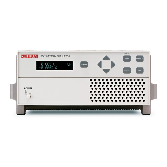
Summary of Contents for Keithley 2302
- Page 1 Model 2302/2302-PJ/2306/2306-PJ/2306-VS Battery/Charger Simulator Quick Results Guide A G R E A T E R M E A S U R E O F C O N F I D E N C E...
- Page 2 WARRANTY Keithley Instruments, Inc. warrants this product to be free from defects in material and workmanship for a period of 1 year from date of shipment. Keithley Instruments, Inc. warrants the following items for 90 days from the date of shipment: probes, cables, rechargeable batteries, diskettes, and documentation.
- Page 3 Model 2302/2302-PJ/2306/2306-PJ/2306-VS Battery/Charger Simulator Quick Results Guide ©1999, Keithley Instruments, Inc. All rights reserved. Cleveland, Ohio, U.S.A. Third Printing, June 2003 Document Number: 2306-903-01 Rev. C...
- Page 4 Revision B (Document Number 2306-903-01) ..............May 2000 Revision C (Document Number 2306-903-01) ..............June 2003 All Keithley product names are trademarks or registered trademarks of Keithley Instruments, Inc. Other brand names are trademarks or registered trademarks of their respective holders.
- Page 5 Keithley products are designed for use with electrical signals that are rated Measurement Category I and Measurement Category II, as described in the International Electrotechnical Commission (IEC) Standard IEC 60664. Most measurement, control, and data I/O signals are Measurement Category I and must not be directly connected to mains voltage or to voltage sources with high transient over-voltages.
- Page 6 (Note that selected parts should be purchased only through Keithley Instruments to maintain accuracy and functionality of the product.) If you are unsure about the applicability of a replacement component, call a Keithley Instruments office for information.
-
Page 7: Table Of Contents
Table of Contents Introduction ................... Performance features ..............Proper connection of the supply to the DUT ........ Front panel operation ..............Menu controls ................ Setting the output voltage, current range, and current limit .. Turning supply output ON/OFF ..........Actual V and I mode .............. DVM input mode .............. - Page 9 In this guide, references to Model 2306 apply to all of the simulators unless otherwise noted. Likewise, references to specific models (for example, Model 2306, 2306-PJ, or 2306-VS, or Model 2302 or 2302-PJ) refer only to the models listed. Since the Model 2302 and 2302-PJ are single channel battery simulators, functions related to the second channel (i.e., the charger channel) are not available for these...
-
Page 10: Introduction
Introduction Introduction This guide is designed to familiarize users of the Keithley Model 2306 Dual Channel Battery/ Charger Simulator and Model 2302 Single Channel Battery Simulator with the basic operating features available from the instrument’s front panel and also the GPIB bus. The sequence of operating instructions reflects the order in which the instrument would be configured for a... -
Page 11: Performance Features
Introduction Performance features The battery channel, the single output channel of the Model 2302 and channel #1 on the Model 2306, has several enhanced performance features: 1. The transient response, defined by the voltage recovery time and voltage drop when subjected to a 1000% load change, is faster. -
Page 12: Proper Connection Of The Supply To The Dut
Proper connection of the supply to the DUT Proper connection of the supply to the DUT WARNING When installing a unit into a test system, make sure the external power sources do not apply voltage to the power supply in excess of its maximum limits (see specifications). -
Page 13: Figure 3 Rear Panel View Of Model 2306-Vs
Proper connection of the supply to the DUT Figure 3 Rear panel view of Model 2306-VS WARNING: NO INTERNAL OPERATOR SERVICABLE PARTS,SERVICE BY QUALIFIED PERSONNEL ONLY. ISOLATION FROM EARTH: 22 VOLTS MAX. OUTPUT #2 OUTPUT #1 DVM IN +30 VDC MAX. SOURCE SENSE SOURCE... -
Page 14: Front Panel Operation
Front panel operation Failure to connect the sense leads in this fashion will severely compromise the performance of Model 2306 with dynamic loads. Figure 5 illustrates the proper connection of the supply to the DUT using a 2-wire local sense configuration. Figure 5 2-wire local sense connection of the DUT to the output Quick Disconnect... -
Page 15: Setting The Output Voltage, Current Range, And Current Limit
Setting the output voltage, current range, and current limit Output voltage can be set from 0 to 15V. For the Model 2306, 2306-VS, and 2302, there are two ranges for current, 5A and 5mA. For the Model 2306-PJ and 2302-PJ, there are also two ranges for current, 5A and 500mA. - Page 16 Front panel operation NPLC rate The integration (reading) rate of the instrument is specified as a parameter based on the number of power-line cycles (NPLC), where 1 PLC for 60Hz line frequency is 16.67msec. In general, the fastest integration time (0.01 PLC) results in increased reading noise. The slowest integration time (10 PLC) provides the best common-mode and normal-mode rejection.
- Page 17 Front panel operation Programming examples: outputting and reading back V and I The following command sequences demonstrate how to output voltage and current, and read back (measure) the actual voltage and current: Battery channel (#1) Command Description VOLT 5 ‘ Set output voltage to 5V. SENS:CURR:RANG:AUTO ON ‘...
-
Page 18: Dvm Input Mode
Front panel operation DVM input mode The DVM input display mode must be selected in order to measure voltage applied to DVM input of the power supply. This display mode is selected as follows: 1. Press the DISPLAY key to access the display menu. DISPLAY TYPE #1 (battery channel active) or DISPLAY TYPE #2 (charger channel active) will appear on the top line of the display. -
Page 19: Figure 6 Pulsed Waveform
Front panel operation The high measurement is triggered on the rising edge of the pulse (Figure 6) and an integration is performed for the time specified for the high measurement. The falling edge of the pulse triggers the low measurement, and an integration is performed for the time specified for the low measurement. -
Page 20: Figure 7 Eliminating The Effect Of A Current Transient On A Pulse Current Measurement
Front panel operation current The pulsed response of a device is rarely a perfect square wave. Figure 7 shows the response of a typical GSM handset during the transmit portion of the data frame. Using the built in auto-time feature with a trigger threshold of 0.2 amp and no trigger delay, the µ... - Page 21 Press the OPERATE key after setting the appropriate voltage and current limits for the DUT. Select CURRENT RANGE For Models 2306-PJ and 2302-PJ, select 500mA or 5A. For Models 2306, 2306-VS, and 2302, the 5A range is automatically selected. Set trigger level and range “TRIG LEVEL RANGE”...
- Page 22 Front panel operation Integration time (auto time setting) “AUTO TIME” sub-menu Press ENTER when “ACQUIRE TIMES” appears on the display. If the correct trigger level is selected in the previous step and the DUT is operating, the Model 2306 will automatically determine the HIGH, LOW, and AVERAGE times.
-
Page 23: Figure 8 Circuit — Determining The Dynamic Voltage And Current Characteristics Of A Dut
Front panel operation NOTE No Pulses Detected message If no pulses are detected, current will not be measured (i.e., -----A), and the “NO PULSE” message will be displayed. The “NO PULSE” message is displayed with dashes or the last valid pulse reading. Dashes are shown if the pulse-current measurement settings are not appropriate for detecting pulses. - Page 24 Front panel operation Programming examples: pulse current measurements The following command sequence will return the average of 10 peak pulse current measurements: Battery channel (#1) Command Description SENS:RANG 5 ‘ Select 5A range. VOLT 15 ‘ Set output voltage to 15V. CURR 0.75 ‘...
- Page 25 Front panel operation Charger channel (#2) Command Description SENS2:RANG 5 ‘ Select 5A range. SOUR2:VOLT 15 ‘ Set output voltage to 15V. SOUR2:CURR 0.75 ‘ Set current limit to 750mA. OUTP2 ON ‘ Turn output on. SENS2:PCUR:SYNC ON ‘ Enable trigger synchronization. SENS2:PCUR:AVER 10 ‘...
-
Page 26: Long Integration Mode
Turn on the output Press the OPERATE key after setting the appropriate voltage and current limits for the DUT. Select CURRENT RANGE For Models 2306-PJ and 2302-PJ, select 500mA or 5A. For Models 2306, 2306-VS, and 2302, the 5A range is automatically selected. - Page 27 100mA range: 0–100mA in 0.1 mA steps “TRG LEV mA RANGE” and “TRIG LEVEL mA” sub-menus Battery Channel (#1) (Models 2306-PJ and 2302-PJ) — On the 500mA current range, the trigger level can be set for either the 500mA, 100mA, or the 10mA range.
- Page 28 Front panel operation Automatically setting long integration time (“AUTO TIME” sub-menu) Press ENTER when “LINT AUTOTIME #1, #2”, “ACQUIRE TIMES” appears on the display. If the correct trigger level is selected in the previous step and the DUT is operating, the Model 2306 will automatically determine the INTEGRATION times.
- Page 29 Front panel operation Programming examples: long integration measurements The following command sequence will trigger and return one long integration measurement: Battery channel (#1) Command Description SENS:RANG 5 ‘ Select 5A range. VOLT 15 ‘ Set output voltage to 15V. CURR 0.75 ‘...
-
Page 30: Advanced Features
Advanced features Advanced features Simulating battery impedance The electronic resistance of batteries varies according to a variety of factors such as chemistry, cell construction, number of charge/discharge cycles, temperature, and depth of discharge. If a battery is used as a source in a circuit with a dynamic load, changes in the voltage across the load will be produced proportional to the electronic resistance of the battery and other sources of resistance in the circuit. -
Page 31: Figure 11
Advanced features Figure 11 shows the actual performance of typical Li ion, NiMH, and NiCd handset battery packs with a dynamic load, shown in Figure 12, simulating a GSM handset during transmission. The pulse minimum voltage is the voltage at the battery terminals during the transmit, or high current portion, of the data frame. -
Page 32: Figure 12
Advanced features Figure 12 Simulated GSM phone current profile Voltage Pulse Minimum Voltage -0.030 amps Current -1.200 amps NOTE The simulated GSM phone current profile contained in Figure 12 shows a standby current of 0.030A, a transmit current of 1.2A, and the pulse minimum voltage during the transmit frame. -
Page 33: Figure 13
Advanced features Figure 13 Electronic resistance of NiCd, NiMH, and Li ion battery packs 0.40 Li ion 0.35 0.30 NiMH 0.25 0.20 NiCd 0.15 0.10 10.0 Time, hrs NOTE Figure 13 shows electronic resistance for battery packs during a simulated GSM phone pulsed discharge from full charge to 5.5 volts. -
Page 34: Figure 14
Advanced features Figure 14 Effect of variable output impedance control ~1.4 amps 70mV 140mV NOTE Figure 14 contains the effect of the variable output impedance control of the Model 2306 on the current and voltage performance of a GSM handset. -
Page 35: Figure 15
Advanced features Two methods are used to determine the impedance value of the cell or battery pack. The first method uses data from the battery manufacturer or another source and is simply entered into the Model 2306 from the front panel or over the GPIB bus. The second method involves a simple series of measurements as follows. -
Page 36: Variable Output Bandwidth
Advanced features Figure 16 Voltage drop sample (with Model 2306 and output impedance set at 0.24Ω) V H – V L = 0.360V Variable output bandwidth Testing the performance of the battery charger circuitry in a handset does not require the high bandwidth performance in channel #1 or channel #2 of the Model 2306. -
Page 37: External Triggering
Advanced features External triggering NOTE External triggering and associated voltage stepping discussed below is available only via remote with the Model 2306-VS. See Section 6 of the Model 2306 Instruction Manual for more detailed information on these features. Description The Model 2306-VS has four rear panel mounted BNC connectors (two inputs and two out- puts) allowing external triggering and handshaking for both channels. - Page 38 Advanced features External trigger commands There are a number of commands that support Model 2306-VS external triggering and associated voltage stepping. See Table 6-1 in Section 6 of the Model 2306 Instruction Manual for details. Programming example: external triggering with voltage stepping The command sequence below will step through six voltages from 1V to 6V without taking readings.
- Page 39 Index NPLC rate Actual V and I mode Performance features Advanced features Programming example Average readings external triggering with voltage stepping Programming examples long integration measurements DVM input mode making voltage measurements with the outputting and reading back V and I External trigger commands pulse current measurements External triggering...
- Page 42 Specifications are subject to change without notice. All Keithley trademarks and trade names are the property of Keithley Instruments, Inc. All other trademarks and trade names are the property of their respective companies. Keithley Instruments, Inc. 28775 Aurora Road • Cleveland, Ohio 44139 • 440-248-0400 • Fax: 440-248-6168 1-888-KEITHLEY (534-8453) •...
Need help?
Do you have a question about the 2302 and is the answer not in the manual?
Questions and answers