
Related Manuals for Keithley 2260B Series


Summary of Contents for Keithley 2260B Series
- Page 1 www.keithley.com 2260B Series 360W and 720W Multi-Range Programmable DC Power Supplies Programming Manual Rev. A / March 2014 A Greater Measure of Confidence A Tektronix Company...
- Page 2 Series 2260B 360W and 720W Multi-Range Programmable DC Power Supplies PROGRAMMING MANUAL ISO-9001 CERTIFIED MANUFACTURER...
- Page 3 This manual contains proprietary information, which is protected by copyright. All rights are reserved. No part of this manual may be photocopied, reproduced or translated to another language without prior written consent. The information in this manual was correct at the time of printing. However, we continue to improve our products and reserve the rights to change specification, equipment, and maintenance procedures at any time without notice.
-
Page 4: Table Of Contents
Table of Contents Table of Contents SAFETY INSTRUCTIONS ........... 2 GETTING STARTED ............6 2260B Series Overview ........... 7 Appearance ............9 Configuration Settings ......... 15 REMOTE CONTROL ............20 Interface Configuration ........21 ... -
Page 5: Safety Instructions
2260B Series Programming Manual AFETY INSTRUCTIONS This chapter contains important safety instructions that you must follow during operation and storage. Read the following before any operation to insure your safety and to keep the instrument in the best possible condition. - Page 6 SAFETY INSTRUCTIONS Do not dispose electronic equipment as unsorted municipal waste. Please use a separate collection facility or contact the supplier from which this instrument was purchased. Safety Guidelines Do not place any heavy object on the General Guideline • instrument.
- Page 7 2260B Series Programming Manual Disconnect the power cord before cleaning. Cleaning the • Instrument Use a soft cloth dampened in a solution of mild • detergent and water. Do not spray any liquid. Do not use chemicals containing harsh material •...
- Page 8 SAFETY INSTRUCTIONS Power cord for the United Kingdom When using the instrument in the United Kingdom, make sure the power cord meets the following safety instructions. NOTE: This lead/appliance must only be wired by competent persons WARNING: THIS APPLIANCE MUST BE EARTHED IMPORTANT: The wires in this lead are coloured in accordance with the following code: Green/ Yellow:...
-
Page 9: Getting Started
After going through the overview, please read the theory of operation to become familiar with the operating modes, protection modes and other safety considerations. 2260B Series Overview ............7 Series lineup ........................ 7 Main Features ......................8 Appearance ................ 9 2260B Front Panel ..................... -
Page 10: 2260B Series Overview
GETTING STARTED 2260B Series Overview Series lineup The 2260B series consists of 4 models, divided into 2 different model types covering 2 power capacities: 360W models and 720W models. Model name Type Voltage rating Current rating Power 2260B-30-36 360W models 0~30V... -
Page 11: Main Features
2260B Series Programming Manual Main Features High performance/power Performance • Power efficient switching type power supply • Low impact on load devices • Fast transient recovery time of 1ms • Fast output response time • OVP, OCP and OTP protection Features •... -
Page 12: Appearance
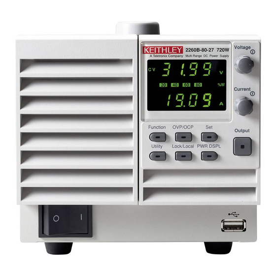
GETTING STARTED Appearance 2260B Front Panel 2260B-80-27, 2260B-30-72 (720W) 2260B-80-13, 2260B-30-36 (360W) - Page 13 2260B Series Programming Manual The Function keys along with the Output key will Function Keys light up when a key is active. The Function key is used to configure the power supply. Set the overcurrent or overvoltage protection levels. Sets the current and voltage limits.
- Page 14 GETTING STARTED Sets the voltage. Voltage Knob Sets the current. Current Knob Press to turn on the output. The Output Output key will light up when the output is active. The USB A port is used to update the firmware. The firmware can only be updated at a service center.
-
Page 15: Rear Panel
2260B Series Programming Manual Rear Panel 2260B-80-27, 2260B-30-72 (720W) 2260B-80-13, 2260B-30-36 (360W) - Page 16 GETTING STARTED Standard 26 pin MIL connector Analog Control Connector (OMRON XG4 IDC plug). The analog control connector is used to monitor current and voltage output, machine status (OVP, OCP, OTP etc.), and for analog control of the current and voltage output. Use an OMRON XG5 IDC socket as the mating socket.
- Page 17 2260B Series Programming Manual 360W models: 2260B-30-36/2260B- Line Voltage Input 80-13 720W models: 2260B-30-72/2260B- 80-27 Voltage Input: 100~240 VAC • Line frequency: 50Hz/60 Hz • (Automatically switchable)
-
Page 18: Configuration Settings
GETTING STARTED Configuration Settings Setting Configuration Settings The normal configuration settings (F-01~F-61, Background F-88, F-89) are used to configure or view system settings. Use the following operation steps when configuring the interface settings used in the Remote Control chapter on page 20. Ensure the load is not connected. - Page 19 2260B Series Programming Manual 4. Use the Current knob to set the parameter for the chosen F setting. 5. Press the Voltage knob to save the configuration setting. Conf will be displayed when successful. Press the Function key again to exit Exit the configuration settings.
- Page 20 GETTING STARTED 0.01A/s~72.00A/s (2260B-30-36) 0.1A/s~144.0A/s (2260B-30-72) Rising current slew rate F-06 0.01A/s~27.00A/s (2260B-80-13) 0.01A/s~54.00A/s (2260B-80-27) 0.01A/s~72.00A/s (2260B-30-36) 0.1A/s~144.0A/s (2260B-30-72) Falling current slew rate F-07 0.01A/s~27.00A/s (2260B-80-13) 0.01A/s~54.00A/s (2260B-80-27) 0.000Ω~0.833Ω (2260B-30-36) Internal resistance 0.000Ω~0.417Ω (2260B-30-72) F-08 setting 0.000Ω~5.926Ω (2260B-80-13) 0.000Ω~2.963Ω (2260B-80-27) Bleeder circuit control F-09 0 = OFF, 1 = ON...
- Page 21 2260B B Series Programm ming Manual Gatewa ay-3 F-49 0~255 Gatewa ay-4 F-50 0~255 DNS ad ddress -1 F-51 0~255 DNS ad ddress -2 F-52 0~255 DNS ad ddress-3 F-53 0~255 DNS ad ddress-4 F-54 0~255 Socket s active F-57 0 = Dis able, 1 = Enable Web Se...
- Page 22 GETTING STARTED External Out Logic F-94 0 = High ON, 1 = Low ON Power Switch trip F-95 0 = Enable , 1 = Disable Calibration Settings* Calibration F-00 0000 ~ 9999 Power On and Calibration settings can only be set *Note during power up.
-
Page 23: Remote Control
2260B Series Programming Manual EMOTE CONTROL This chapter describes basic configuration of IEEE488.2 based remote control. Interface Configuration ............. 21 Socket Server Examples ............ 32 Command Syntax .............. 36 Command List ..............39... -
Page 24: Interface Configuration
REMOTE CONTROL Interface Configuration USB Remote Interface ............21 Configure GPIB Interface ........... 22 Configure Ethernet Connection ......... 23 USB Remote Control Function Check ......25 Web Server Remote Control Function Check ....26 Socket Server Function Check ..........26 USB Remote Interface Type A, host PC side... -
Page 25: Configure Gpib Interface
2260B Series Programming Manual Configure GPIB Interface To use GPIB, the optional GPIB to USB adapter (2260B-GPIB-USB) must be used. The GPIB to USB adapter must be connected before the 2260B is turned on. Only one GPIB address can be used at a time. -
Page 26: Configure Ethernet Connection
Ethernet can be configured for basic remote control or monitoring using a web server or it can be configured as a socket server. The 2260B series supports DHCP connections so the instrument can be automatically connected to an existing network or alternatively, network settings can be manually configured. - Page 27 2260B Series Programming Manual 2. Press the Function key to enter the Page 9 Normal configuration settings. Set the following LAN settings: F-36 = 1 Enable LAN F-37 = 1 Turn DHCP to enable F-59 = 1 Turn the web server on...
-
Page 28: Usb Remote Control Function Check
REMOTE CONTROL F-46 = 0 Subnet Mask part 4 of 4 F-43 = 172 Gateway part 1 of 4 F-44 = 16 Gateway part 2 of 4 F-45 = 21 Gateway part 3 of 4 F-46 = 101 Gateway part 4 of 4 F-57 = 1 Enable Sockets The socket function is only available for firmware... -
Page 29: Web Server Remote Control Function Check
2260B Series Programming Manual Web Server Remote Control Function Check Enter the IP address of the power supply in a Functionality web browser after the instrument has been check configured as a web server (page 23). http:// XXX.XXX.XXX.XXX The web browser interface appears. - Page 30 REMOTE CONTROL 2. From the Configuration panel access; My System>Devices and Interfaces>Network Devices 3. Press Add New Network Device>Visa TCP/IP Resource… 4. Select Manual Entry of Raw Socket from the popup window.
- Page 31 2260B Series Programming Manual 5. Enter the IP address and the port number of the 2260B. The port number is fixed at 2268. 6. Double click the Validate button. 7. Next configure the Alias (name) of the 2260B connection. In this example the Alias is: PS_DC1 8.
- Page 32 REMOTE CONTROL 9. The IP address of the 2260B will now appear under Network Devices in the configuration panel. Select this icon now. 10. Press Open VISA Test Panel.
- Page 33 2260B Series Programming Manual 11. Under the Template > Property Node tabs, set Termination Char Enable from the Attribute Name list to VI_TRUE. 12. Under the Basic I/O >Write tabs, Enter the *IDN? query into the Buffer, if it is not already there.
- Page 34 REMOTE CONTROL 14. In the Basic I/O > Read tabs, the return parameter for the *IDN? query should be returned to the buffer area: XXXXXXX,AAA-AAA,,T1.12.20111013 Where: XXXXXXX = Manufacturer, AAA-AAA = Model number. For further details, please see the following Note programming examples.
-
Page 35: Socket Server Examples
2260B Series Programming Manual Socket Server Examples Visual Basic Example............32 C++ Example ............... 33 LabVIEW Example .............. 35 Visual Basic Example The following visual basic programming Background example uses the VISA COM 3.0 Type Library. The example will connect to the 2260B using the IP address of 172.15.5.133 over port 2268. - Page 36 REMOTE CONTROL C++ Example The following program creates a connection to Background the 2260B and sets the voltage to 3.3 volts and the current 1.5 amps. The voltage and current reading is then read back and the connection is closed. Add visa32.lib to the project library when Note building the following sample program.
- Page 37 2260B Series Programming Manual...
- Page 38 REMOTE CONTROL LabVIEW Example The following picture shows a LabView Background programming example for the 2260B.
-
Page 39: Command Syntax
2260B Series Programming Manual Command Syntax Partial compatibility IEEE488.2 Compatible Partial compatibility Standard SCPI, 1999 SCPI commands follow a tree-like structure, Command Structure organized into nodes. Each level of the command tree is a node. Each keyword in a SCPI command represents each node in the command tree. - Page 40 REMOTE CONTROL A query is a simple or Query compound command followed by a question mark (?). A parameter (data) is returned. meas:curr:dc? Example Two or more commands on Compound the same command line. Compound commands are separated with either a semi- colon (;) or a semi-colon and a colon (;:).
- Page 41 2260B Series Programming Manual Commands and queries have two different Command Forms forms, long and short. The command syntax is written with the short form of the command in capitals and the remainder (long form) in lower case. The commands can be written in capitals or lower-case, just so long as the short or long forms are complete.
-
Page 42: Command List
REMOTE CONTROL integers 0, 1, 2, 3 <NR1> decimal 0.1, 3.14, 8.5 <NR2> numbers floating point 4.5e-1, 8.25e+1 <NR3> any of NR1, 2, 3 1, 1.5, 4.5e-1 <NRf> String parameters are any ASCII <string> characters (ASCII: 20H to 7EH) that are enclosed in either single or double quotes. - Page 43 2260B Series Programming Manual OUTPut:DELay:ON ............47 Output OUTPut:DELay:OFF ............47 Commands OUTPut:MODE ..............48 OUTPut[:STATe][:IMMediate] .......... 48 OUTPut[:STATe]:TRIGgered ..........48 OUTPut:PROTection:CLEar ..........50 OUTPut:PROTection:TRIPped ......... 50 STATus:OPERation[:EVENt] ........... 51 Status STATus:OPERation:CONDition ........51 Commands STATus:OPERation:ENABle ..........51 STATus:OPERation:PTRansition ........52 STATus:OPERation:NTRansition ........
- Page 44 REMOTE CONTROL SYSTem:CONFigure:BTRip:PROTection ....... 65 SYSTem:CONFigure:CURRent:CONTrol ....... 66 SYSTem:CONFigure:VOLTage:CONTrol ...... 66 SYSTem:CONFigure:MSLave ..........67 SYSTem:CONFigure:OUTPut:EXTernal[:MODE] ..67 SYSTem:CONFigure:OUTPut:PON[:STATe] ....67 SYSTem:COMMunicate:ENABle ........68 SYSTem:COMMunicate:GPIB[:SELF]:ADDRess ..69 SYSTem:COMMunicate:LAN:IPADdress ....... 69 SYSTem:COMMunicate:LAN:GATEway ......69 ...
-
Page 45: Abort Commands Abort
2260B Series Programming Manual Abort Commands ABORt ................... 42 ABORt The ABORt command will cancel any triggered Description actions. Syntax ABORt APPLy Commands APPLy ..................42 APPLy Query The APPLy command is used to set both the Description voltage and current. The voltage and current will be output as soon as the function is executed if the programmed values are within the accepted range. -
Page 46: Display Display:menu[:Name]
REMOTE CONTROL <NRf> 0% ~ 105% of the rated output Parameter <voltage> voltage. <NRf> 0% ~ 105% of the rated output <current> current. 0 volts/0 amps Maxium value for the present range. Return parameter <NRf> Returns the voltage and current. Example APPL 5.05,1.1 Sets the voltage and current to 5.05V and 1.1A. -
Page 47: Commands Display[:Window]:Text:clear
2260B Series Programming Manual Example DISP:MENU:NAME 0 Sets the display to the Voltage/Current display screen. DISPlay[:WINDow]:TEXT:CLEar Clears the text on the main screen from the Description DISPlay[:WINDow]:TEXT[:DATA] command . Syntax DISPlay[:WINDow]:TEXT:CLEar DISPlay[:WINDow]:TEXT[:DATA] Query Sets or queries the data text that will be written to Description the display. -
Page 48: Display:blink
REMOTE CONTROL DISPlay:BLINk Query Turns blink on or off for the display. Description Syntax DISPlay:BLINk { 0 | 1 | OFF | ON } Query Syntax DISPlay:BLINk? <NR1>Turns blink OFF Parameter Turns blink OFF <NR1> Turns blink ON Turns blink ON <NR1>Turns blink OFF Return parameter 0 <NR1>Turns blink ON... -
Page 49: Measure Measure[:Scalar]:Current[:Dc]
2260B Series Programming Manual Measure Commands MEASure[:SCALar]:CURRent[:DC]........46 MEASure[:SCALar]:VOLTage[:DC] ......... 46 MEASure[:SCALar]:POWer[:DC] ........46 MEASure[:SCALar]:CURRent[:DC] Query Takes a measurement and returns the average Description output current Syntax MEASure[:SCALar]:CURRent[:DC]? Returns the current in amps. Return parameter <NRf> MEASure[:SCALar]:VOLTage[:DC] Query Takes a measurement and returns the average Description output voltage. -
Page 50: Output:delay:on
REMOTE CONTROL Output Commands OUTPut:DELay:ON............47 OUTPut:DELay:OFF ............47 OUTPut:MODE..............48 OUTPut[:STATe][:IMMediate] .......... 48 OUTPut[:STATe]:TRIGgered ..........48 OUTPut:PROTection:CLEar ..........50 OUTPut:PROTection:TRIPped ......... 50 OUTPut:DELay:ON Query Sets the Delay Time in seconds for turning the Description output on. -
Page 51: Output:mode
2260B Series Programming Manual OUTPut:MODE Query Sets the 2260B output mode. This is the equivalent Description to the F-03 (V-I Mode Slew Rate Select) settings. Syntax OUTPut:MODE {<NR1>|CVHS|CCHS|CVLS|CCLS} Return Syntax OUTPut:MODE? CV high speed priority Parameter CV high speed priority... - Page 52 REMOTE CONTROL <NR1>Turns the output off when a software Parameter trigger is generated. Turns the output off when a software trigger is generated. <NR1>Turns the output on when a software trigger is generated. Turns the output on when a software trigger is generated.
-
Page 53: Output:protection:clear
2260B Series Programming Manual OUTPut:PROTection:CLEar Clears over-voltage, over-current and over- Description temperature (OVP, OCP, OTP) protection circuits. It also clears the shutdown protection circuit. The AC failure protection cannot be cleared. Syntax OUTPut:PROTection:CLEar OUTPut:PROTection:TRIPped Query Returns the state of the protection circuits (OVP, Description OCP, OTP). -
Page 54: Status Commands
REMOTE CONTROL Status Commands STATus:OPERation[:EVENt] ........... 51 STATus:OPERation:CONDition ........51 STATus:OPERation:ENABle ..........51 STATus:OPERation:PTRansition ........52 STATus:OPERation:NTRansition ........52 STATus:QUEStionable[:EVENt] ........52 STATus:QUEStionable:CONDition ......... 53 STATus:QUEStionable:ENABle ........53 STATus:QUEStionable:PTRansition ......... 53 STATus:QUEStionable:NTRansition ........ -
Page 55: Status:operation:ptransition
2260B Series Programming Manual 0~32767 Parameter <NRf> 0~32767 Return parameter <NR1> STATus:OPERation:PTRansition Query Sets or queries the bit sum of the positive Description transition filter of the Operation Status register. Syntax STATus:OPERation:PTRansition <NRf> STATus:OPERation:PTRansition? 0~32767 Parameter <NRf> 0~32767 Return parameter <NR1>... -
Page 56: Status:questionable:condition
REMOTE CONTROL STATus:QUEStionable:CONDition Query Queries the status (bit sum) of the Questionable Description Status register. This query will not clear the register. Query Syntax STATus:QUEStionable:CONDition? 0~32767 Parameter <NRf> 0~32767 Return parameter <NR1> STATus:QUEStionable:ENABle Query Sets or queries the bit sum of the Questionable Description Status Enable register. -
Page 57: Status:preset
2260B Series Programming Manual 0~32767 Parameter <NRf> 0~32767 Return parameter <NR1> STATus:PRESet This command resets the ENABle register, the Description PTRansistion filter and NTRansistion filter on the Operation Status and Questionable Status Registers. The registers/filters will be reset to a default value. - Page 58 REMOTE CONTROL Source Commands [SOURce:]CURRent[:LEVel][:IMMediate][:AMPLitude]55 [SOURce:]CURRent[:LEVel]:TRIGgered[:AMPLitude] . 56 [SOURce:]CURRent:PROTection[:LEVel] ...... 56 [SOURce:]CURRent:PROTection:STATe ......57 [SOURce:]CURRent:SLEW:RISing ........57 [SOURce:]CURRent:SLEW:FALLing ....... 57 [SOURce:]RESistance[:LEVel][:IMMediate][:AMPLitude] ....................58 [SOURce:]VOLTage[:LEVel][:IMMediate][:AMPLitude] ....................58 [SOURce:]VOLTage[:LEVel]:TRIGgered[:AMPLitude] 59 [SOURce:]VOLTage:PROTection[:LEVel] ...... 59 ...
-
Page 59: [Source:]Current:protection[:Level]
2260B Series Programming Manual [SOURce:]CURRent[:LEVel]:TRIGgered [:AMPLitude] Query Sets or queries the current level in amps when a Description software trigger has been generated. Syntax [SOURce:]CURRent[:LEVel]:TRIGgered[:AMPLitude] {<NRf>|MIN|MAX} Query Syntax [SOURce:]CURRent[:LEVel]:TRIGgered[:AMPLitude]? [MIN|MAX] 0%~105% of the rated current output in amps. Parameter/Return <NRf>... -
Page 60: [Source:]Current:protection:state
REMOTE CONTROL [SOURce:]CURRent:PROTection:STATe Query Turns OCP (over-current protection) on or off. Description Syntax [SOURce:]CURRent:PROTection:STATe {0|1|OFF|ON} Query Syntax [SOURce:]CURRent:PROTection:STATe? <NR1> Turns the buzzer off. Parameter/Return 0 Turns the buzzer off. <NR1> Turns the buzzer on. Turns the buzzer on. Returns bleeder resistor status (0 or 1). Return parameter <Bool>... -
Page 61: [Source:]Resistance[:Level][:Immediate][:Amplitude]
2260B Series Programming Manual Query Syntax [SOURce:]CURRent:SLEW:FALLing? [MIN|MAX] 0.01A/s~200% (2260B-30-36) Parameter/Return NRf 0.1A/s~200% (2260B-30-72) 0.01A/s~200% (2260B-80-13) 0.01A/s~200% (2260B-80-27) Minimum falling current slew rate Maximum falling current slew rate Example SOUR:CURR:SLEW:FALL 1 Sets the falling current slew rate to 1A/s. [SOURce:]RESistance[:LEVel][:IMMediate]... -
Page 62: [Source:]Voltage[:Level]:Triggered[:Amplitude]
REMOTE CONTROL 0~105% of the rated output voltage in volts. Parameter/Return <NRf> Minimum voltage level Maximum voltage level Example SOUR:VOLT:LEV:IMM:AMPL 10 Sets the voltage level to 10 volts. [SOURce:]VOLTage[:LEVel]:TRIGgered [:AMPLitude] Query Sets or queries the voltage level in volts when a Description software trigger has been generated. -
Page 63: [Source:]Voltage:slew:rising
2260B Series Programming Manual [SOURce:]VOLTage:SLEW:RISing Query Sets or queries the rising voltage slew rate. This is Description only applicable for CV slew rate priority mode. Syntax [SOURce:]VOLTage:SLEW:RISing {<NRf>|MIN|MAX} Query Syntax [SOURce:]VOLTage:SLEW:RISing? [MIN|MAX] 0.01V/s--200% (2260B-30-XX) Parameter/Return <NRf> 0.1V/s--200% (2260B-80-XX) Minimum rising voltage slew rate. -
Page 64: Trigger Commands
REMOTE CONTROL Trigger Commands The trigger commands generate and configure software triggers. This power supply supports the following two trigger functions. • TRANsient Specifies the current and voltage settings in advance and uses the trigger to set them. Please refer to VOLT:TRIG, CURR:TRIG on page 56 and 62 for details. -
Page 65: Trigger:output[:Immediate]
2260B Series Programming Manual Example: TRIG:TRAN:SOUR IMM Immediate Mode CURR:TRIG MAX VOLT:TRIG 5 INIT:NAME TRAN The current changes to the maximum, and the voltage changes to 5V. Example: TRIG:TRAN:SOUR BUS Bus Mode CURR:TRIG MAX VOLT:TRIG 5 INIT:NAME TRAN TRIG:TRAN The current changes to the maximum, and the voltage changes to 5V. - Page 66 REMOTE CONTROL Example: TRIG:OUTP:SOUR IMM Immediate Mode OUTP:TRIG 1 INIT:NAME OUTP The output changes to ON. Example: TRIG:OUTP:SOUR BUS Bus Mode OUTP:TRIG 1 INIT:NAME OUTP TRIG:OUTP The output changes to ON.
-
Page 67: System System:configure:beeper[:State]
2260B Series Programming Manual System Function Command SYSTem:CONFigure:BEEPer[:STATe]......64 SYSTem:CONFigure:BLEeder[:STATe] ......65 SYSTem:CONFigure:BTRip[:IMMediate] ......65 SYSTem:CONFigure:BTRip:PROTection ....... 65 SYSTem:CONFigure:CURRent:CONTrol ....... 66 SYSTem:CONFigure:VOLTage:CONTrol ...... 66 SYSTem:CONFigure:MSLave ..........67 SYSTem:CONFigure:OUTPut:EXTernal[:MODE] ..67 SYSTem:CONFigure:OUTPut:PON[:STATe] ....67 SYSTem:COMMunicate:ENABle ........68 SYSTem:COMMunicate:GPIB[:SELF]:ADDRess ..69 SYSTem:COMMunicate:LAN:IPADdress ....... 69 SYSTem:COMMunicate:LAN:GATEway ...... -
Page 68: Commands System:configure:bleeder[:State]
REMOTE CONTROL Returns the buzzer status. Return parameter <Boolean> SYSTem:CONFigure:BLEeder[:STATe] Query Sets or queries the status of the bleeder resistor. Description Syntax SYSTem:CONFigure:BLEeder[:STATe] {OFF|ON|0|1} Query Syntax SYSTem:CONFigure:BLEeder[:STATe]? <NR1> Turns the bleeder resistor off. Parameter Turns the bleeder resistor off. <NR1> Turns the bleeder resistor on. Turns the bleeder resistor on. -
Page 69: System:configure:current:control
2260B Series Programming Manual Returns power switch trip setting. Return parameter <Boolean> SYSTem:CONFigure:CURRent:CONTrol Query Sets or queries the CC control mode (local control Description (panel), external voltage control, external resistance control). This setting is applied only after the power is cycled. -
Page 70: System:configure:mslave
REMOTE CONTROL SYSTem:CONFigure:MSLave Query Sets or queries the unit operation mode. This Description setting is only applied after the power has been cycled. Syntax SYSTem:CONFigure:MSLave { 0 | 1 | 2 | 3 | 4 } Query Syntax SYSTem:CONFigure:MSLave? Parameter/Return <NR1> Description Master/Local Master/Parallel 1 (2 units) -
Page 71: System:communicate:enable
2260B Series Programming Manual Syntax SYSTem:CONFigure:OUTPut:PON[:STATe] {OFF|ON|0|1} Query Syntax SYSTem:CONFigure:OUTPut:PON[:STATe]? Output off at power up Parameter Output off at power up Output on at power up Output on at power up Output off at power up Return Parameter 0 Output on at power up... -
Page 72: System:communicate:gpib[:Self]:Address
REMOTE CONTROL SYSTem:COMMunicate:GPIB[:SELF]:ADDR Query Sets or queries the GPIB address. This setting is Description only applied after the power has been cycled. Syntax SYSTem:COMMunicate:GPIB[:SELF]:ADDRess <NR1> Query Syntax SYSTem:COMMunicate:GPIB[:SELF]:ADDRess? 0~30 Parameter/Return <NR1> Example SYST:COMM:GPIB:SELF:ADDR 15 Sets the GPIB address to 15. SYSTem:COMMunicate:LAN:IPADdress Query Sets or queries LAN IP address. -
Page 73: System:communicate:lan:smask
2260B Series Programming Manual SYSTem:COMMunicate:LAN:SMASk Query Sets or queries the LAN subnet mask. This setting Description is only applied after the power has been cycled. Syntax SYSTem:COMMunicate:LAN:SMASk <string> Query Syntax SYSTem:COMMunicate:LAN:SMASk? Subnet mask in string format ( “mask”) Parameter/Return <string>... -
Page 74: System:communicate:lan:dns
REMOTE CONTROL SYSTem:COMMunicate:LAN:DNS Query Sets or queries the DNS address. This setting is Description only applied after the power has been cycled. Syntax SYSTem:COMMunicate:LAN:DNS <string> Query Syntax SYSTem:COMMunicate:LAN:DNS? DNS in string format ( “mask”) Parameter/Return <string> Applicable ASCII characters: 20H to 7EH Example SYST:COMM:LAN:DNS “172.16.1.252”... -
Page 75: System:communicate:lan:web:password
2260B Series Programming Manual SYSTem:COMMunicate:LAN:WEB:PASSword Query Sets or queries the web password. This setting is Description only applied after the power has been cycled. Syntax SYSTem:COMMunicate:LAN:WEB:PASSword <NR1> Query Syntax SYSTem:COMMunicate:LAN:WEB:PASSword? 0 ~ 9999 Parameter/Return <NR1> SYST:COMM:LAN:WEB:PASS 1234 Example Set the web password as 1234. -
Page 76: System:klock
REMOTE CONTROL Returns an error code followed by Paramter/Return <NR1>,<string> an error message as a string. The string is returned as “string”. Example SYSTem:ERRor? -100, “Command error” SYSTem:KLOCk Query Enables or disables the front panel key lock. Description Syntax SYSTem:KLOCk { OFF | ON | 0 | 1} Query Syntax SYSTem:KLOCk? Panel keys unlocked... -
Page 77: System:preset
2260B Series Programming Manual SYSTem:PRESet Resets all the settings to the factory default Description settings. See page 98 for details. This command is identical in effect to the *RST command. Syntax SYSTem:PRESet SYSTem:VERSion Query Returns the version of the SCPI specifications that Description the unit complies with. -
Page 78: Common *Cls
REMOTE CONTROL *CLS The *CLS command clears the Standard Event Description Status, Operation Status and Questionable Status registers. The corresponding Enable registers in each of the above registers are not cleared. If a <NL> newline code immediately precedes a *CLS command, the Error Que and the MAV bit in the Status Byte Register is also cleared. -
Page 79: Opc
2260B Series Programming Manual Returns the instrument identification as a Return parameter <string> string in the following format: XXXXXX,AAAAAA,TW123456,01.00.20110101 Manufacturer: XXXXXX Model number : AAAAAA Serial number : TW123456 Firmware version : 01.00.20110101 *OPC Query The *OPC command sets the OPC bit (bit0) of the... -
Page 80: Stb
REMOTE CONTROL 0~255 Parameter <NR1> Returns the bit sum of the Service Request Return parameter <NR1> Enable register. *STB Query Queries the bit sum of the Status Byte register with Description MSS (Master summary Status). Query Syntax *STB? Returns the bit sum of the Status Byte register Return parameter <NR1>... -
Page 81: Status Register Overview
Overview status of the power supply. The status registers maintain the status of the protection conditions, operation conditions and instrument errors. The 2260B Series have a number of register groups: Questionable Status Register Group • Standard Event Status Register Group •... - Page 82 REMOTE CONTROL The Status Registers...
- Page 83 2260B Series Programming Manual Questionable Status Register Group The Questionable Status Register Group Overview indicates if any protection modes or limits have been tripped. Bit Summary Event Bit # Weight OV (Over-Voltage) Over voltage protection has been tripped OC (Over-Current)
- Page 84 REMOTE CONTROL OT (Over Temperature) Over temperature protection has been tripped VL (Voltage Limit) Voltage limit has been reached CL (Current Limit) Current limit has been reached SD (Shutdown Alarm) 2048 PL (Power-Limit) 4096 The Questionable Status Condition Register Condition indicates the status of the power supply.
- Page 85 2260B Series Programming Manual Operation Status Register Group The Operation Status Register Group indicates Overview the operating status of the power supply. Bit Summary Event Bit # Weight CAL (Calibration mode) Indicates if the 2260B is in calibration mode. WTG (Waiting for trigger) Indicates if the 2260B is waiting for a trigger.
- Page 86 REMOTE CONTROL CV (Constant voltage mode) Indicates if the 2260B is in CV mode. CC (Constant current mode) 1024 Indicates if the 2260B is in CC mode. OND (Output ON Delay) 2048 Indicates if Output ON delay time is active OFD (Output OFF Delay) 4096 Indicates if Output OFF delay...
- Page 87 2260B Series Programming Manual The Enable register determines which Enable Register registered Events in the Event Register will be used to set the OPER bit in the Status Byte Register.
- Page 88 REMOTE CONTROL Standard Event Status Register Group The Standard Event Status Register Group Overview indicates if any errors have occurred. The bits of the Event register are set by the error event queue. Bit Summary Event Bit # Weight OPC (Operation complete) The OCP bit is set when all selected pending operations are complete.
- Page 89 2260B Series Programming Manual EXE (Execution Error) The EXE bit indicates an execution error due to one of the following: illegal command parameter, parameter out of range, invalid parameter, the command didn’t execute due to an overriding operation condition. CME (Command Error) The CME bit is set when a syntax error has occurred.
- Page 90 REMOTE CONTROL Status Byte Register & Service Request Enable Register The Status Byte register consolidates the status Overview events of all the status registers. The Status Byte register can be read with the *STB? query and can be cleared with the *CLS command. Bit Summary Event Bit #...
- Page 91 2260B Series Programming Manual (ESB) Event Summary Bit. The ESB is the summary bit for the Standard Event Status Register group. MSS Bit The MSS Bit is the summary of the Status Byte Register and Service Request register (bits 1-5, 7).
-
Page 92: Error List
REMOTE CONTROL Error List Command Errors ..............89 Execution Errors ..............93 Device Specific Errors ............95 Query Errors ................. 96 Command Errors Overview An <error/event number> in the range [ -199 , - 100 ] indicates that an IEEE 488.2 syntax error has been detected by the instrument’s parser. - Page 93 2260B Series Programming Manual Error Code Description This is the generic syntax error for devices that -100 Command cannot detect more specific errors. This code Error indicates only that a Command Error as defined in IEEE 488.2,11.5.1.1.4 has occurred. An unrecognized command or data type was -102 Syntax error encountered;...
- Page 94 REMOTE CONTROL The header contains more that twelve -112 Program characters (see IEEE 488.2, 7.6.1.4.1). mnemonic too long The header is syntactically correct, but it is -113 Undefined header undefined for this specific device; for example, *XYZ is not defined for any device. The value of a numeric suffix attached to a -114 Header program mnemonic, see Syntax and Style...
- Page 95 2260B Series Programming Manual Either the character data element contains an -141 Invalid character data invalid character or the particular element received is not valid for the header. A legal character data element was encountered -148 Character data not allowed where prohibited by the device.
- Page 96 REMOTE CONTROL Execution Errors Overview An <error/event number> in the range [ -299 , - 200 ] indicates that an error has been detected by the instrument’s execution control block. The occurrence of any error in this class shall cause the execution error bit (bit 4) in the event status register (IEEE 488.2, section 11.5.1) to be set.
- Page 97 2260B Series Programming Manual Indicates that a command is not executable -201 Invalid while in local while the device is in local due to a hard local control (see IEEE 488.2, 5.6.1.5); for example, a device with a rotary switch receives a message...
- Page 98 REMOTE CONTROL Indicates that a legal program data element was -222 Data out of range parsed but could not be executed because the interpreted value was outside the legal range as defined by the device (see IEEE 488.2, 11.5.1.1.5.). Used where exact value, from a list of possible -224 Illegal values, was expected.
- Page 99 2260B Series Programming Manual or query errors; see the other error definitions in this section. Error Code Description Indicates that some error, termed “system -310 System error error” by the device, has occurred. This code is device-dependent. Indicates that the firmware detected a fault -320 Storage fault when using data storage.
- Page 100 REMOTE CONTROL Error Code Description This is the generic query error for devices that -400 Query error cannot detect more specific errors. This code indicates only that a Query Error as defined in IEEE 488.2, 11.5.1.1.7 and 6.3 has occurred.
-
Page 101: Appendix
2260B Series Programming Manual PPENDIX 2260B Default Settings The following default settings are the factory configuration settings for the power supply. Default Setting Initial Settings Output LOCK 0 (Disabled) Voltage Current Maximum Maximum Normal Function Settings Setting Default Setting Output ON delay time F-01 0.00s... - Page 102 APPENDIX Bleeder circuit control F-09 1 = ON Buzzer ON/OFF control F-10 1 = ON USB/GPIB setting Rear Panel USB Mode F-22 2 = USB CDC GPIB address F-23 LAN setting F-36 1 = Enable DHCP F-37 1 = Enable Sockets active F-57 1 = Enable...
-
Page 103: Error Messages & Messages
2260B Series Programming Manual Error Messages & Messages The following error messages or messages may appear on the 2260B screen during operation. Error Messages Description Err 001 USB Mass Storage is not present Err 002 No (such)file in USB mass storage... -
Page 104: Index
INDEX NDEX Caution symbol ......2 List of features ......8 Cleaning the instrument ..... 4 Messages ........100 Configuration Model differences ......7 table ..........16 Power on/off Display format ......100 safety instruction ......3 Disposal instructions ....4 Rear panel diagram .... - Page 105 All other trademarks and trade names are the property of their respective companies. Keithley Instruments, Inc. Corporate Headquarters • 28775 Aurora Road • Cleveland, Ohio 44139 • 440-248-0400 • Fax: 440-248-6168 • 1-888-KEITHLEY • www.keithley.com A Greater Measure of Confidence A Tektronix Company ...
Need help?
Do you have a question about the 2260B Series and is the answer not in the manual?
Questions and answers