
Related Manuals for Ametek 5920 UHP


Summary of Contents for Ametek 5920 UHP
- Page 1 USER MANUAL 5920 UHP Moisture Analyzer for Ultra-High Purity Gases PN 592047901 Rev YC...
- Page 2 AMETEK Process Instruments assumes no responsibility or liability for any errors or inaccuracies that may appear in this document. AMETEK Process Instruments is not responsible for any infringement of patents or other rights of third parties that may result from the use of this document. The content of this document is furnished for informational purposes only, is subject to change without notice, and does not represent a commitment or guaranty by AMETEK Process Instruments.
-
Page 3: Table Of Contents
Contents Safety Notes ..............................vii Electrical Safety ............................viii Grounding ..............................viii Sample Gas ............................... viii Personnel and Equipment Safety Information................ix Special Warnings and Information ......................xi Equipment Used in Class I, Division 2 Hazardous Locations ..........xi Gas Compatibility Warning ......................xii Warning Labels ............................xiv Environmental Information –... - Page 4 Simple Acknowledge ......................2-28 Acknowledge with Data .....................2-29 Failure .............................2-29 Variables Table ............................2-30 CONTROLLER/INTERFACE ....................3-1 Working From the Built-in User Interface ..................3-1 Zero Key .............................3-3 Alarm Key ............................3-4 Range Key ............................3-5 PN 592047901 Rev YC iv | 5920 UHP Moisture Analyzer...
- Page 5 Sample Gas ..........................3-8 Clock ............................3-9 Zero Schedule ........................3-10 System Test ..........................3-11 Working From the 5920 UHP Configurator Software ............. 3-12 Configurator Software Installation ..................3-12 Configuring the 5920 ......................... 3-13 Working From the General Tab ..................3-13 Saving Analyzer Configuration Settings ................3-15 Working From the Device Communication Tab ............3-16...
- Page 6 SPECIFICATIONS ........................5-1 Compatible Gases ...........................5-1 5920 UHP Moisture Analyzer Specifications .................5-2 Approvals and Certifications ......................5-3 5920 UHP Moisture Analyzer Directives and Standards ...........5-3 APPENDIX A – QUICK REFERENCE CARD ................A-1 PN 592047901 Rev YC vi | 5920 UHP Moisture Analyzer...
-
Page 7: Safety Notes
Safety Notes WARNINGS, CAUTIONS, and NOTES contained in this manual emphasize critical instructions as follows: Important information that should not be overlooked. An operating procedure which, if not strictly observed, may result in personal injury or environmental contamination. An operating procedure which, if not strictly observed, may result in damage to the equipment. -
Page 8: Electrical Safety
Check the sample line and all connections for leaks before powering up. Consult plant safety personnel for appropriate exhaust venting guidelines for specific sample gas type. PN 592047901 Rev YC viii | 5920 UHP Moisture Analyzer... -
Page 9: Personnel And Equipment Safety Information
Personnel and Equipment Safety Information This section describes important safety information to avoid personal injury and dam- age to the equipment while installing, operating, maintaining, or servicing the equip- ment. All safety regulations, standards, and procedures at the analyzer location must be followed. - Page 10 Do Not Operate in Explosive Atmosphere To avoid injury or fire hazard, do not operate this product in an explosive atmosphere unless you have purchased options that are specifically designed for these environments. PN 592047901 Rev YC x | 5920 UHP Moisture Analyzer...
-
Page 11: Special Warnings And Information
Special Warnings and Information Equipment Used in Class I, Division 2 Hazardous Locations This equipment is designed to meet requirements for Class I, Division 2, Groups ABCD, or Non-Hazardous areas only. Explosion Hazard – Substitution of Components May Impair Suitability for Class I, Division 2. -
Page 12: Gas Compatibility Warning
The mains plug must be of the locking and grounding type. The external RS-485 communications circuits represent a non-incendive field wiring connection. The maximum length of data cable to be used is 4000 feet (1220 meters). PN 592047901 Rev YC xii | 5920 UHP Moisture Analyzer... - Page 13 Electromagnetic Compatibility (EMC) Read and follow the recommendations in this section to avoid performance variations or damage to the internal circuits of this equipment when installed in harsh electrical environments. The various configurations of the 5920 Moisture Analyzer should not produce, or fall victim to, elec- tromagnetic disturbances as specified in the European Union’s EMC Directive.
-
Page 14: Warning Labels
Achtung – Heiße Oberfläche Environmental Information – WEEE This AMETEK product contains materials that can be reclaimed and recycled. In some cases the product may contain materials known to be hazardous to the environ- ment or human health. In order to prevent the release of harmful substances into the environment and to conserve our natural resources, AMETEK recommends that you arrange to recycle this product when it reaches its “end of life. -
Page 15: Overview
Overview The 5920 Moisture Analyzer measures trace concentrations of moisture in ultra-high purity gases such as air, oxygen, hydrogen, helium, argon, air, neon, xenon and nitrogen at concentrations down to 1 parts-per-billion by volume (PPBV) using a quartz crystal microbalance sensor. Calibrated range is 0–150 parts-per-billion by volume (PPBV) with a trend indication for measured con- centrations above the calibrated range. -
Page 16: Controller/Communications
• An 18-button keypad on the front of the unit that is used to set or change operating parameters and system values. • Serial interface to an external PC. 1-2 | 5920 UHP Moisture Analyzer PN 592047901 Rev YC... -
Page 17: Contact Closure Signals
Contact Closure Signals The analyzer provides the following contact closure signals. System Alarm Activates (contact opens) when a condition exists that makes analyzer output questionable. Such conditions include: • Cell Temperature alarm • Zero error • Battery alarm Moisture Concentration Alarm Activates (contact opens) when a moisture concentration exceeds the pro- grammed alarm levels. -
Page 18: Moisture Sensor
The difference between these two frequency measurements is known as the delta frequency (∆ ƒ). The ∆ ƒ value is a function of the moisture con- centration in the sample gas. 1-4 | 5920 UHP Moisture Analyzer PN 592047901 Rev YC... -
Page 19: Gas Flow
Gas Flow Sample System The 5920 Moisture Analyzer sample system enables the analyzer to make reli- able water vapor measurements at concentrations down to 1 PPBV. It serves several purposes. 1. It controls the sample conditions at the sensor assembly (e.g., flow rate, temperature, pressure). - Page 20 Sensor Gas B Purifier Purifier OPEN CLOSED. Sample Gas Flow/Path = Diaphragm Valve Reference Gas Flow/Path = Solenoid Valve MFM = Mass Flow Meter Figure 1-2. Flow during Reference cycle. 1-6 | 5920 UHP Moisture Analyzer PN 592047901 Rev YC...
-
Page 21: Solenoid Valves
Solenoid Valves The sensor assembly is connected to both legs of the analyzer, and immedi- ately downstream of the connection points, there are two (2) solenoid valves (SV1 and SV2). These two solenoid valves switch the flow of the Sample and dry Reference gases through the QCM sensor. -
Page 22: Verification With External Challenges
Verification with External Challenges Unlike previous AMETEK UHP moisture analyzers, the 5920 does not contain an internal moisture standard. In AMETEK’s line of QCM-based moisture analyzers, the primary purpose of the internal moisture standard is to monitor the sen- sor’s response characteristics and to enable on-line compensation for sensitiv- ity changes that occur over time. -
Page 23: Zero Cycle
AMETEK recommends performing a Zero every 24 hours for the first month of operation. After this start-up period, the analyzer will have dried down sufficiently to increase the Zero interval to 1 week. AMETEK recommends that the duration of the Zero cycle be set to 48 (i.e., 2 hours). - Page 24 5900 analyzers is estimated to reach 10 % (i.e., a 2 PPBV change at 20 PPBV) after 45 months of service. Even though the QCM-based moisture analyzers are extremely stable, AMETEK recommends that you check the calibration of the analyzer every three (3) years.
-
Page 25: Installation And Start-Up
Installation and Start-Up Safety Considerations This chapter contains information about the installation and setup of the 5920 UHP Moisture Analyzer. Before beginning the installation of the analyzer and before powering it up, review and follow all safety information following the Table of Contents near the beginning of this manual. -
Page 26: Pre-Installation Requirements
Always use gloves when working on the analyzer. 2-2 | 5920 UHP Moisture Analyzer PN 592047901 Rev YC... -
Page 27: Analyzer Requirements
Analyzer Requirements Space Requirements The 5920 Moisture Analyzer requires an area 48 cm wide x 17.7 cm high x 50.9 cm deep (19" x 7" x 20") plus rear clearance for analyzer connections and proper ventilation (Figure 2-1). It should be located as close to the sample tap as possible. -
Page 28: Tools, Equipment, And Supplies Required For Installation
Unpacking and Inspecting the Equipment Remove any packing material from the 5920 UHP Moisture Analyzer ship- ping crate. Check for damage. If equipment is damaged, notify the carrier and contact AMETEK (https://www.ametekpi.com/customersupport/aftermarket) immediately if parts are missing or damage is found, and to verify if damaged parts will require replacement prior to safely installing and operating the ana- lyzer/equipment. -
Page 29: Environmental Requirements
Environmental Requirements • 10 °C to 30 °C (50 °F to 86 °F) • 90 % RH maximum, non-condensing • IEC Pollution Degree 2 • IEC Installation Category II • Maximum elevation 2,000 meters (6560 feet) • Indoor use only, IEC 529; IP40 Electrical Requirements The 5920 Moisture Analyzer must be installed in a general purpose area. -
Page 30: Utility Requirements
Minimum input pressure: 138 kPa (20 PSIG) Maximum pressure: 345 kPa (50 PSIG) If necessary, a UHP Pressure Regulator can be installed at the main process shut-off valve. 2-6 | 5920 UHP Moisture Analyzer PN 592047901 Rev YC... -
Page 31: Analyzer Installation
Analyzer Installation Consult plant safety personnel for appropriate exhaust venting guide- lines for specific Sample gas type. Refer to the “Special Warnings and Information” section in the begin- ning of this manual for information on sample gas compatibility. RS-232 and RS-485 Connections (Item 4 in Figure 2-2) – Do not Con- nect or Disconnect when energized. -
Page 32: User-Supplied Items
Optimal results are obtained with the sample line maintained at 60 °C. Recommended Sample gas input tubing is 1/4-inch OD, electro-pol- ished 316L VAR stainless steel (AMETEK Part No. 257707002 or equiva- lent). •... -
Page 33: Rear Panel Connections And User Interface Board
Rear Panel Connections and User Interface Board See Figures 2-2 and 2-3 for location of analyzer connections on Rear Panel and User Interface board. Remove terminal cover to access this board. Item Function Power Conduit Cable gland for analyzer power cord. Signal Conduit Cable gland for signal connections. -
Page 34: Gas Connections
Instrument Air 1/4-inch Swagelok fitting (Item 3). If the cleanliness of the air supply is questionable, connect using oil/air separators. 5. Check all sample input and Exhaust fittings for leaks. Check all Sample gas input and Exhaust fittings for leaks. 2-10 | 5920 UHP Moisture Analyzer PN 592047901 Rev YC... -
Page 35: Electrical Connections
Only qualified service personnel may access the interior of the analyzer. If qualified service personnel are not available, contact AMETEK Service. Voltage Selection The 5920 Analyzer comes from the factory set to operate on 115 VAC. If you must switch the setting to 230 VAC (or back to the 115 VAC setting), follow the procedure below. -
Page 36: Power Installation
- ring connector termination, etc. LINE VOLTAGE RS-485 TERMINATOR FUSE ANALOG OUTPUT DATA CONC SYSTEM POWER VALID ALARM ALARM CONNECTOR 1 (L) (LINE) 2 (N) (NEUTRAL) Figure 2-5. Remove 1 (L) and 2 (N). 2-12 | 5920 UHP Moisture Analyzer PN 592047901 Rev YC... - Page 37 6. Feed the strain relief cap with compression bushing onto the new cord and tighten securely as per original. If the new cord is a smaller diameter than the original, consider using the alternate bushing that is included with the European cord.
-
Page 38: Communication Connections
CONC SYSTEM Terminator VALID ALARM ALARM Fuse Receptacle RS-485 Power Connector Serial Port Alarm & Alert Contacts Analog Output Figure 2-7. Communication connections on the 5920 Analyzer User Interface board. 2-14 | 5920 UHP Moisture Analyzer PN 592047901 Rev YC... -
Page 39: Class I, Division 2 Electrical Connections (Alternative) - Hardwire
Class I, Division 2 Electrical Connections (Alternative) – Hardwire As an alternative, in a Class I, Division 2 classified area, you can use the wiring method requirements found in the NEC 501-4(b) or CEC 18-152 for conduit connection to the analyzer. When the analyzer is hard-wired into the facility’s power system, using this method, it is considered “permanently connected equipment”... -
Page 40: Rs-485 Communications
CONTROL 2 wire SHLD Converter TDA(-) TDB(+) RDA(-) RDB(+) To PC RS485 IN Power Analyzer +12V Supply Figure 2-8. (type DB9M) CONTROL ECHO RS-232 to RS-485 Conversion for Host PC. 2-16 | 5920 UHP Moisture Analyzer PN 592047901 Rev YC... -
Page 41: Signal Connections (4-20 Ma)
Signal Connections (4–20 mA) EXPLOSION HAZARD For Division 2 areas, the power supply should be shut down for service or maintenance. If a procedure requires that power remain on, a hot work permit may be required. Consult your safety specialist. 100 to 500 ohms Figure 2-9.1. -
Page 42: Analyzer Setup
Scroll up, down, left, and right through menu items and system value lists. Number keys (0–9) Enter values. Use the (-) and (.) to enter negative values or numbers that require a decimal point. 2-18 | 5920 UHP Moisture Analyzer PN 592047901 Rev YC... - Page 43 To highlight an item, scroll through the menu items until the small arrowheads point to your choice as shown in Figure 2-11. Up and Down arrow symbols dis- played on the right-hand side of the screen indicate that there are more menu items above or below the currently displayed items.
-
Page 44: Overview Of Display
Line 2 Status message Line 3 Alarm message Line 4 Alarm value There is also a series of dots after the “Status” message that “beat” to indicate the analyzer is functioning. 2-20 | 5920 UHP Moisture Analyzer PN 592047901 Rev YC... -
Page 45: Initial Start-Up
Initial Start-Up 1. Open the main sample shutoff valve at the source. Maximum inlet pressure is 50 PSIG. Damage can occur if higher pres- sures are introduced to the analyzer. 2. Turn on the AC power at the source. Boot-up information will appear on the display followed by the default normal operation screen (Figure 2-13). -
Page 46: Procedure For Speeding Up The Dry Down Period
3. After 3–4 days, the analyzer setup can be returned to normal operation (e.g., the factory default values). 2-22 | 5920 UHP Moisture Analyzer PN 592047901 Rev YC... -
Page 47: Performing An Initial Zero
Performing an Initial Zero To start the initial Zero cycle: 1. Press the Zero key. 2. Press the ‘8’ key (arrow down) until you see “Zero” between the arrows. Select “Zero” by pressing the Enter key. This initial Zero cycle takes approximately two (2) hours. When the Zero cycle is complete, the analyzer will adjust the offset and automatically return to normal sampling. -
Page 48: Configuring The 5920 Analyzer For Serial Communications
The checksum is a two-byte ASCII hexadecimal field representing the modulo 256 sum of Node Address, Command Byte, and Data fields (ex- cludes the start flag). • A master can issue a wildcard in lieu of a checksum. 2-24 | 5920 UHP Moisture Analyzer PN 592047901 Rev YC... - Page 49 The checksum for a slave response is the modulo 256 sum of all characters pre- ceding the checksum including the response code. The message format for slave responses containing a data field is illustrated in Figure 2-15. Data End Flag Figure 2-15.
-
Page 50: Special Addresses
Echo (A) Echo implements a loop back function to test the integrity of the serial com- munication. Any text transmitted by the master is returned. Example: Master: >99ABCDEFG4E[CR] Slave: AABCDEFG1D[CR] 2-26 | 5920 UHP Moisture Analyzer PN 592047901 Rev YC... -
Page 51: Bad Command (B)
Bad Command (B) This command is not recognized by the slave. It will therefore result in a type 01 failure response. Example: Master: >99BB4[CR] Slave: N01[CR] Acknowledge (C) Requests a simple acknowledge from the slave. Useful to determine if there is a device at that node address. -
Page 52: Write Cell Eeprom (L)
Failure message. Simple Acknowledge If the received command does not require data to be returned, a simple ac- knowledge consisting of an ASCII ‘A’ will be sent. Example: Slave: A[CR] 2-28 | 5920 UHP Moisture Analyzer PN 592047901 Rev YC... -
Page 53: Acknowledge With Data
Acknowledge with Data If a command issued by the master requires data in response, an Acknowledge with Data response will be issued. This response consists of an ACSII ‘A’ fol- lowed by data and checksum. Example: Slave: A0123456A6[CR] Failure All failure responses consist of an ASCII ‘N’ followed by a two-byte hexadecimal ASCII failure code. -
Page 54: Variables Table
Wet minus Dry reading Float 0.0 Hz Flow1 Reference channel flow Float 60.0 sccm Flow2 Total flow Float 120 sccm AirTemperature Oven air temperature Float 60.0 degree C Figure 2-19.1. Variables table. 2-30 | 5920 UHP Moisture Analyzer PN 592047901 Rev YC... - Page 55 Name Description Type Typical Value ValveState 0-Sample, 2-Reference, 3-Zero Integer Hour Analyzer time set Integer Minute Analyzer time set Integer Second Analyzer time set Integer Month Analyzer date set Integer Analyzer date set Integer Year Analyzer date set Integer 2001 Date Analyzer date String[11] 01/24/01...
- Page 56 This page intentionally left blank. 2-32 | 5920 UHP Moisture Analyzer PN 592047901 Rev YC...
-
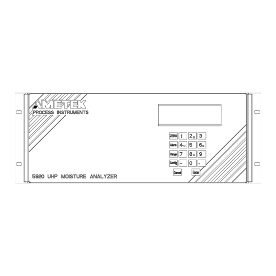
Page 57: Controller/Interface
Controller/Interface The user interface consists of the display screen on the front of the 5920 Mois- ture Analyzer and the keypad. Using a combination of the function keys and the number, minus sign and decimal point, you can set the parameters for your analyzer. - Page 58 Test Keypad Open Contacts Test Alarms Close Contacts 4 mA Output Test Analog 12 mA Output Figure 3-2. 20 mA Output Menu map for 5920 Moisture Test Serial Start Analyzer. Cancel 3-2 | 5920 UHP Moisture Analyzer PN 592047901 Rev YC...
-
Page 59: Zero Key
Zero Key Use the Zero key to define on-demand Zero settings. ZERO Hold Outputs Enable Disable Adjust Offset Enable Disable Start Zero Figure 3-3. Quit Zero Main Menu, Zero key. Hold Outputs Enable Select this function to hold the output at the last valid reading during a Zero. -
Page 60: Alarm Key
High Limit Enter the high limit value in PPBV. Low Limit Enter the low limit value in PPBV. Enable Alarm Select Enable or Disable to activate the moisture concentration alarm relay. 3-4 | 5920 UHP Moisture Analyzer PN 592047901 Rev YC... -
Page 61: Range Key
Range Key Use the Range key to define your 4–20 mA output setting. Use this setting to scale the 4–20 mA output. The 4–20 mA output is propor- tional to the moisture readings. RANGE Maximum Conc Enter Value Figure 3-5. Minimum Conc Enter Value Main Menu, Range key. -
Page 62: Config Key
Enter a value from 1–9. The default is '5' . Back Light Select On or Off. The default is On. Font This is a factory-set parameter that identifies the type used for the display on the analyzer. 3-6 | 5920 UHP Moisture Analyzer PN 592047901 Rev YC... -
Page 63: Communication
Communication Select communication setup. Config Communication Node Enter Address Address 9600 Baud Rate 19200 RS-485 Two Wire Figure 3-6.3. Mode Four Wire Communication menu. optional Node Address Enter the address for RS-485 serial communications (0–240). Address 240 is reserved (see the “Special Addresses” section in Chapter 2 for details). Baud Rate Select the baud rate at which you transfer data (9600 or 19200). -
Page 64: Sample Gas
Figure 3-6.4. Sample Gas menu. Refer to the “Special Warnings and Information” section in the begin- ning of this manual for information on sample gas compatibility. 3-8 | 5920 UHP Moisture Analyzer PN 592047901 Rev YC... -
Page 65: Clock
Clock Use this function to set the clock on your analyzer. Config Clock Year Enter Value Enter Value Sunday Day of Monday Week Tuesday Wednesday Month Enter Value Thursday Friday Saturday Hour Enter Value Figure 3-6.5. Minute Enter Value Clock menu. Year Enter the 4-digit value for the year. -
Page 66: Zero Schedule
AMETEK recommends performing a Zero every 24 hours for the first month of operation. After this start-up period, the analyzer will have dried down sufficiently to increase the Zero interval to 1 week. AMETEK recommends that the duration of the Zero cycle be set to 48 (i.e., 2 hours). -
Page 67: System Test
System Test Use the System Test key to perform tests on various components of the ana- lyzer. Figure 3-6.7. System Test menu. Test Display Tests the display by providing a “checker board” pattern on the display. Test Keypad Tests the keypad by echoing characters to the display. Test Alarms Tests the alarm contacts by toggling them open / close. -
Page 68: Working From The 5920 Uhp Configurator Software
Working From the 5920 UHP Configurator Software The Configurator Software provides a graphical user interface to set up param- eters for either a single analyzer or multiple analyzers. Although you can set and view parameters for multiple analyzers using the 5920 Configurator Software, you can only work with one analyzer at any time. -
Page 69: Configuring The 5920
Configuring the 5920 This section provides instructions for setting up your operating parameters us- ing the Configurator Software. Working From the General Tab Use the General tab to view the current configuration and define parameters for the analyzer and for PC communications (Figure 3-7). After initial setup, any changes to the analyzer communications parameters must be made using the Device Communications tab. - Page 70 Restore the analyzer’s internal parameters from a file. The Open dialog box appears so that you can select and open the file. The Restore configuration button can also be used to restore the analyzer communications parameters. 3-14 | 5920 UHP Moisture Analyzer PN 592047901 Rev YC...
-
Page 71: Saving Analyzer Configuration Settings
Live Data check box Checked The system connects to and uses live data from the analyzer. Not checked The system uses demonstration data. Status message field Indicates if the analyzer is on-line, off-line, or in demo mode. On-Line The PC and analyzer are connected and communicating properly. Off-Line The Live Data box is checked on the General tab and the connection is broken or off-line. -
Page 72: Working From The Device Communication Tab
Click Apply to confirm the change. This may cause the analyzer to go off- • line. • Change the PC settings or physical wires/cables. • Reset the analyzer by recycling power. Figure 3-9. Device Communications setup screen. 3-16 | 5920 UHP Moisture Analyzer PN 592047901 Rev YC... -
Page 73: Saving Your Settings
Parameters on the Device Communications tab include: Baud Rate Select the baud rate at which data will be transferred. RS-485 Identifies the analyzer’s address and the type of serial communication cable that is being used. Address Type the network address for the analyzer being connected. Two-Wire RS-485 Click if you are using a 2-wire cable. -
Page 74: Working From The Setup Tab
20 mA Enter your high analog output limit. 4 mA Enter your low analog output limit. Hold during zero Check this box to hold analyzer output during Verification and Zero. 3-18 | 5920 UHP Moisture Analyzer PN 592047901 Rev YC... - Page 75 Alarm Output Set up the limits for the Concentration alarm. Enable check box Check this box to enable the Concentration alarm. High Limit Enter the high limit for the Concentration alarm. Low Limit Enter the low limit for the Concentration alarm. To Save settings on the Setup tab, click Apply.
-
Page 76: Working From The Schedule Tab
Click Synchronize to set the time, or click Cancel to close the box. Zero Duration Enter the Zero duration in cycles. One cycle is equal to 2.5 minutes. The system defaults to the minimum time required. 3-20 | 5920 UHP Moisture Analyzer PN 592047901 Rev YC... -
Page 77: Saving Your Settings
Scheduled Zero Schedule routine Zero by clicking the Daily, Weekly, or Monthly button. Never No Zero cycle will be done. Scheduling fields at the bottom of the box are not available. Daily To run a Zero cycle select this option and then enter the time of day (1 through 24) in the Hour field at the bottom of this group. -
Page 78: Working From The Status Tab
Working From the Monitor Tab Use the Monitor tab to check on analyzer operation. From this tab you can also collect data from the analyzer. Figure 3-13. Monitor tab. 3-22 | 5920 UHP Moisture Analyzer PN 592047901 Rev YC... -
Page 79: Data Capture
Data Capture The data capture feature allows the user to collect and save analyzer data dis- played on the Monitor tab to an Excel compatible file. Press the On button to start data collection. Specify the file name in the Save As dialog and press the Save button. - Page 80 This page intentionally left blank. 3-24 | 5920 UHP Moisture Analyzer PN 592047901 Rev YC...
-
Page 81: Maintenance And Troubleshooting
Maintenance and Troubleshooting This chapter describes how to request technical support and authorization on returning equipment, and lists spare parts required for general and continued operation. This chapter also includes information about how to replace parts in the 5920 Moisture Analyzer. The operations in this chapter should be performed only by qualified service personnel experienced in electrical safety techniques. -
Page 82: Aftermarket Excellence And Long-Term Commitment To Safety And Quality
Scan the QR code or click the link below to request expert Aftermarket support for parts, repairs, service, training, and more: www.ametekpi.com/customersupport/aftermarket 4-2 | 5920 UHP Moisture Analyzer PN 592047901 Rev YC... -
Page 83: 5920 Uhp Analyzer Replacement Parts
5920 UHP Analyzer Replacement Parts *May require retrofit kit – contact AMETEK Service. Refer to the Figure number listed for the location(s) of the part. Part Description AMETEK Part No. Figure Battery, Lithium 280750043 4-14 Assembly Oven Fans 5910/5920 591069901... -
Page 84: Servicing The 5920 Analyzer
EXPLOSION HAZARD Make sure that power has been disconnected from the analyzer before attempting to remove or replace any of the parts. Figure 4-1. 5920 sampling system. 4-4 | 5920 UHP Moisture Analyzer PN 592047901 Rev YC... -
Page 85: Mass Flow Meter
Mass Flow Meter The Mass Flow Meter (MFM) (AMETEK Part No. 271189001) is attached to the lower section of the MFM mounting bracket. See Figures 4-1 and 4-2. To remove the Mass Flow Meter from the 5920 Analyzer: 1. After power has been disconnected, remove the top cover and sample oven cover from the analyzer and locate the MFM mounting bracket. - Page 86 Gently pull the MFM away from the bracket (Figure 4-3) by sliding it out from the end of the mounting bracket. 9. Disconnect the cable assembly from the MFM. 4-6 | 5920 UHP Moisture Analyzer PN 592047901 Rev YC...
- Page 87 To replace the Mass Flow Meter: 1. Connect the cable assembly to MFM. 2. Slide the new MFM into the mounting bracket and attach it to the bracket using the two (2) hex screws. 3. Replace the MFM mounting bracket, with MFM, solenoids and solenoid bracket attached, in its position on the analyzer mounting plate and attach with screws.
-
Page 88: Solenoid Valves
Two (2) solenoid valves are attached to a solenoid bracket located on the top of the MFM mounting bracket. These valves are labeled SAM (Figures 4-1, 4-2, and 4-5) for the sample solenoid valve assembly (AMETEK Part No. 591016901) and REF for the reference solenoid valve assembly (AMETEK Part No. 591092901). - Page 89 3. Unscrew the female fittings from the solenoid valve to disconnect the at- tached tubing. Discard gaskets. 4. Separate the solenoid valve assembly that you are replacing from the sole- noid bracket by removing the two (2) screws holding it onto the bracket. To replace the Solenoid Valve assembly: 1.
-
Page 90: Pressure Regulator
3. Loosen the nuts that hold the tubing to the VCR ports of the Pressure Regulator and detach the tubing. Discard gaskets and orifice plate. 4. Gently pull the Pressure Regulator out through the open end of the bracket. Figure 4-6. Pressure regulator location. 4-10 | 5920 UHP Moisture Analyzer PN 592047901 Rev YC... - Page 91 To replace the Pressure Regulator assembly: 1. Insert the Pressure Regulator assembly onto the mounting bracket. Make sure that the VCR port labeled “IN” is facing the inlet side of the analyzer. See Figures 4-1 and 4-7. 2. Attach the assembly loosely to the mounting bracket using the two (2) hex screws and lock washers.
-
Page 92: Diaphragm Valve
Diaphragm Valve The Diaphragm Valve (AMETEK Part No. 271221001) is located next to the Pres- sure Regulator on the inlet side of the sampling system. It is attached to the mounting plate using the Diaphragm Valve mounting bracket. To remove the Diaphragm Valve: Follow these instructions to remove the Diaphragm Valve assembly from the 5920 Analyzer. - Page 93 2. Remove the two (2) hex screws and lock washers from the top of the Dia- phragm Valve mounting bracket (Figure 4-9). 3. Loosen the nuts on either side of the Diaphragm Valve. One side is con- nected to tubing and the other to the Purifier. Disconnect both the tubing and the Purifier from the valve.
-
Page 94: Installing The Purifiers
Information” section at the beginning of this manual for more infor- mation. Both gas purifiers must be the same part number for the respective inert/H and oxygen service. Do not mix purifier types. Figure 4-10. Purifiers and VCR nuts. 4-14 | 5920 UHP Moisture Analyzer PN 592047901 Rev YC... - Page 95 To access the Purifier locations: 1. Remove the top cover of the analyzer by removing the two (2) screws on the side and the four (4) screws on the top. 2. Remove the oven insulation cover directly underneath the top cover. 3.
-
Page 96: Maintenance Of The Electronics Module
To remove the Electronics Module from the 5920 Analyzer (see Figure 4-11): 1. Locate the four (4) mounting locations on each of the Electronics Module’s corners. 2. Using the appropriate tool, remove the mounting hardware. 4-16 | 5920 UHP Moisture Analyzer PN 592047901 Rev YC... - Page 97 3. Locate the Stepper Motor and locate the setscrews that hold the universal joint to the side of the Stepper Motor. Using a screwdriver, loosen these retaining screws to separate the universal joint from the shaft of the Stepper Motor. Slide the universal joint away from the motor. Once you remove the Electronics Module from the assembly, you can place it on the analyzer cabinet as a resting fixture.
-
Page 98: Replacing The Stepper Motor
Replacing the Stepper Motor The Stepper Motor (AMETEK Part No. 591087901) is located next to the fan at the front of the Electronics Module assembly. Use Figure 4-11 to locate the Stepper Motor. To remove the Stepper Motor: 1. After locating the Stepper Motor, use the 1/4-inch nut driver to remove the four (4) nuts that hold the Stepper Motor mounting bracket to the Elec- tronics Module plate. -
Page 99: Replacing The Motor Driver Board
Replacing the Motor Driver Board The Motor Driver board (AMETEK Part No. 591053901) is located above the Analog Interface board. Use Figure 4-11 to locate the Motor Driver board. To remove the Motor Drive board: 1. After locating the Motor Driver board, use a screwdriver to remove the two (2) screws that hold the board to the standoffs. -
Page 100: Replacing The Stepper Motor Power Supply Board
Replacing the Stepper Motor Power Supply Board The Stepper Motor Power Supply board (AMETEK Part No. 271135001) is located above the Power Supply board. Use Figure 4-11 to locate the Stepper Motor Power Supply. To remove the Stepper Motor Power Supply board: 1. -
Page 101: Replacing The Analog Interface Board
Replacing the Analog Interface Board The Analog Interface board (AMETEK Part No. 591144902) is located between the Motor Driver board and the MCU board at the rear of the Electronics Mod- ule. Use Figure 4-11 to locate the Analog Interface board. -
Page 102: Replacing The Mcu Board
Motor Driver Board” in this chapter. Replacing the Fan The fan (AMETEK Part No. 591090901) is located at the front of the Electronics Module next to the Stepper Motor. Use Figure 4-11 to locate the fan. To remove the fan: 1. -
Page 103: Replacing The Pilot Valve Manifold
Replacing the Pilot Valve Manifold The Pilot Valve Manifold (AMETEK Part No. 591088901) is found on the side of the Power Supply board. Use Figure 4-11 to locate the Pilot Valve Manifold. To remove the Pilot Valve Manifold: 1. After locating the Pilot Valve Manifold, use a screwdriver to remove the two (2) screws on the top of the manifold. -
Page 104: Board Connections
LCD Display Front Panel DC Power System Alarm (Single) (Dual) Thermistor Sensor LCD Display Front Panel Single Fan and Dual Fan DC Power System Alarm Figure 4-12. Analog Interface board connections. 4-24 | 5920 UHP Moisture Analyzer PN 592047901 Rev YC... -
Page 105: User Interface Board
User Interface Board Heater Wire 120 Volt System RS-485 Alarm 120-Volt System Alarm RS-485 Heater Wire Circuit Side 120-Volt RS-485 System Alarm Figure 4-13. User Interface board connections. Component side and circuit side. PN 592047901 Rev YC Maintenance and Troubleshooting | 4-25... -
Page 106: Mcu Board
MCU Board Battery (Solder Side) RS-232 RS-485 RS-485 P3-1 Reference Valve P3-3 Sample Valve RS-232 Reference Valve P3-1 Sample Valve P3-3 Figure 4-14. MCU board connections. 4-26 | 5920 UHP Moisture Analyzer PN 592047901 Rev YC... -
Page 107: Stepper Motor Board
Stepper Motor Board Motor DC Power DC Power Motor Figure 4-15. Stepper Motor board connections. PN 592047901 Rev YC Maintenance and Troubleshooting | 4-27... -
Page 108: Alarm Messages
Zero analyzer. Check and/or replace Purifier. Contact AMETEK Service if problem persists. Low Battery Alarm Low battery voltage detected. Corrective Action: Battery has to be replaced. Contact AMETEK Service if problem persists. 4-28 | 5920 UHP Moisture Analyzer PN 592047901 Rev YC... - Page 109 Zero Alarm Analyzer performance out of tolerance as detected during Zero cycle. Maximum offset >0.05 Hz). Offset adjustment >0.005 Hz. Corrective Action: Repeat Zero cycle. Contact AMETEK Service if problem persists. Purifier Alarm Purifier failure imminent. Corrective Action: Replace Purifier.
- Page 110 This page intentionally left blank. 4-30 | 5920 UHP Moisture Analyzer PN 592047901 Rev YC...
-
Page 111: Specifications
Specifications Compatible Gases All specifications subject to change without notice. Air, helium, argon, neon, hydrogen, oxygen, nitrogen, and xenon are compat- ible gases. Contact the factory to confirm compatibility with other gases. Read the Gas Compatibility Warning in the “Special Warnings and Information”... -
Page 112: 5920 Uhp Moisture Analyzer Specifications
-40 °C dew point 5 micron filter recommended Mounting 19" rack Dimensions Width: 48 cm (19") Height: 17.7 cm (7") Depth: 50.9 cm (20") Net Weight 15.9 kg (35 lb) 5-2 | 5920 UHP Moisture Analyzer PN 592047901 Rev YC... -
Page 113: Approvals And Certifications
Approvals and Certifications 5920 UHP Moisture Analyzer Directives and Standards Design Classifications Electromagnetic Compatibility Directive: CE EN61326-1 UL61010-1/CSA C22.2 No. 61010-1 Electrical Equipment For Measurement, Control, and Laboratory Use Part1: General requirements ANSI/ISA 12.12.01 Nonincendive Electrical Equipment for use in... - Page 114 This page intentionally left blank. 5-4 | 5920 UHP Moisture Analyzer PN 592047901 Rev YC...
-
Page 115: Appendix A - Quick Reference Card
Appendix A – Quick Reference Card QUICK REFERENCE CARD Reference Chapter 2 of the 5920 UHP Moisture Analyzer User Manual. INSTALLATION AND START-UP ANALYZER PARAMETERS Incoming sample temperature 0 °C and 100 °C Zero key Optimum input gas temperature 60 °C ±5 °C... - Page 116 System Test Test Display Cancel Press Key Test Keypad Open Contacts Test Alarms Close Contacts 4 mA Output Test Analog 12 mA Output 20 mA Output Test Serial Start Cancel A-2 | 5920 UHP Moisture Analyzer PN 592047901 Rev YC...
- Page 117 AMETEK Process Instruments delivers worldwide sales and service support through a network of direct and factory-trained global distribution channels. AMETEK Service Assistance Program plans offer coverage up to 24 hours a day, 365 days of the year. As worldwide experts in the manufacture of process analyzers and instrumentation, we have supplied solutions to industry since 1962, providing the widest range of analysis technology available.
Need help?
Do you have a question about the 5920 UHP and is the answer not in the manual?
Questions and answers