Table of Contents

Advertisement

Quick Links

5830 Moisture Analyzer
User Manual
Process Instruments
PN 583054901 Rev.YA
455 Corporate Boulevard
Confi gurator Version 3.0
Newark, DE 19702

Advertisement

Table of Contents
loading

Summary of Contents for Ametek 5800

  • Page 1 5830 Moisture Analyzer User Manual Process Instruments PN 583054901 Rev.YA 455 Corporate Boulevard Confi gurator Version 3.0 Newark, DE 19702...
  • Page 2 If the instrument or procedures are used for purposes over and above the capabilities specifi ed herein, confi rmation of their validity and suitability should be obtained; otherwise, AMETEK does not guarantee results and assumes no obligation or liability. This publication is not a license to operate under, or a recommendation to infringe upon, any process patents.
  • Page 3: Table Of Contents

    Table of Contents Sample Gas ......................vi Safety Notes ......................vi Electrical Safety .....................vi Grounding ......................vi Warning Labels ....................vii Electromagnetic Compatibility (EMC) ............viii Special Warnings and Information ..............ix Dryer Warning ...................... ix European Standards Information ............... x 
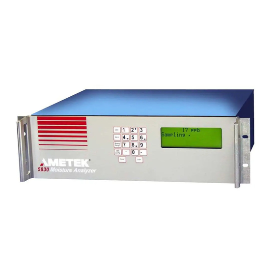
Chapter 1 5830 MOISTURE ANALYZER Overview ......................1-1 Controller / Communications ..............1-2 Contact Closure Signals ................1-2...
  • Page 4 RS-485 communications ...............3-14 Signal Connections (4 to 20 mA ) ............3-15 Overview of keypad ................3-16 Function keys ..................3-16 Overview of display ................3-17 Initial Start-Up ....................3-18 Dry-down period ..................3-18 Procedure for speeding up the dry down period ........3-19 Performing an Initial Zero ................3-19 Chapter 4 User Interface Zero Key .......................4-3...
  • Page 5 Reinstalling the Electronic Module ............7-17 Board Connections ...................7-18 User Interface Board .................7-18 Spare Parts ......................7-19 Appendix A PC Interface AMETEK UHP Moisture Configurator Software ......... A-1 Configurator Software ................A-1 Configurator Software Installation ...............A-1 Configuring the 5830 ..................A-2 Contents | v...
  • Page 6: Sample Gas

    Safety Notes WARNINGS, CAUTIONS, and NOTES contained in this manual emphasize critical instructions as follows: An operating procedure which, if not strictly observed, may result in personal injury or environmental contamination. WARNING An operating procedure which, if not strictly observed, may result in damage to the equipment.
  • Page 7: Warning Labels

    Achtung - Heiße Oberfl äche Environmental Information (WEEE) This AMETEK product contains materials that can be reclaimed and recycled. In some cases the product may contain materials known to be hazardous to the environment or human health. In order to prevent the release of harmful substances into the environment and to conserve our natural resources, AMETEK recommends that you arrange to recycle this product when it reaches its “end of life.”...
  • Page 8: Electromagnetic Compatibility (Emc)

    Electromagnetic Compatibility (EMC) Read and follow the recommendations in this section to avoid performance variations or damage to the internal circuits of this equipment when installed in harsh electrical environments. CAUTION The various configurations of the 5830 Moisture Analyzer should not produce, or fall victim to, electromagnetic disturbances as specified in the European Union’s EMC Directive.
  • Page 9: Special Warnings And Information

    SPECIAL WARNINGS AND INFORMATION EQUIPMENT USED IN CLASS I, DIVISION 2 HAZARDOUS LOCATIONS Explosion Hazard - Substitution of Components May Impair Suitability for Class I, Division 2. WARNING Risque d’explosion - La substitution de composants peut rendre ce materiel inaccept- able pour les emplacements de Classe I, Division 2.
  • Page 10: Chapter 1 5830 Moisture Analyzer

    Declare under our sole responsibility that the product Moisture Analyzer Product Name: Models 5800, 5830, 5812 & 2850 Model Number (s): Conforms to the following standards: EMC Directive 2014/30/EU: EN 55011: 2009 + A1:2010 Industrial, Scientific and medical equipment – Class A, Group 1...
  • Page 11 Process photometric analyzers, process moisture analyzers, and sampling systems are warranted to perform the intended measurement, only in the event that the customer has supplied, and AMETEK has accepted, valid sample stream composition data, process conditions, and electrical area classification prior to order acknowledgment.
  • Page 12 This page intentionally left blank. xii | 5830 Moisture Analyzer...
  • Page 13: Overview

    5830 MOISTURE ANALYZER Overview The Model 5830 Moisture Analyzer reliably measures low concentrations of moisture in high purity gases at concentrations down to 20 parts-per- billion by volume (PPBV), using a quartz crystal microbalance (QCM) sensor. The calibrated range of the analyzer is 0 to 100 PPMV with a trend indication for measured concentrations to 1000 PPMV.
  • Page 14: Controller / Communications

    Controller / Communications All analyzer functions are controlled by microprocessors housed within the analyzer. These include: One fully configurable analog output (4 to 20 mA) that can be self-  powered or externally powered. Three alarm contacts (data valid, concentration alarm, and system ...
  • Page 15: Moisture Sensor

    Moisture Sensor Quartz Crystal Microbalance (QCM) The 5830 analyzer uses a quartz crystal microbalance sensor to measure water vapor concentration. This is a piezoelectric device that is capable of extremely sensitive mass measurement. To make the QCM sensitive to water vapor the surface is coated with a thin film of hygroscopic material. When gas flows through the sensor, the coating absorbs or desorbs mois- ture, changing the natural resonance frequency of the crystal.
  • Page 16: Sample Flow

    The 5830 sample system’s design provides a means of challenging the analyzer with a known source of dry gas to both validate the baseline readings and to compensate for any minor changes in background offsets. In addition, the analyzer contains a permeation tube-based moisture standard that can be used to challenge the analyzer with a known moisture concentration.
  • Page 17: Solenoid Valves

    you reduce the time required to equilibrate all portions of the sample system that exist upstream of the bypass valve. A capillary tube, located immediately downstream of SV1 (the coil shape in Figure 1-2), limits the flow rate to approximately 1 standard liter per minute (the exact value of the bypass flow is a function of the inlet pressure to the analyzer).
  • Page 18: Zero Gas Module

    After this start-up period, the analyzer will have  dried down sufficiently to increase the zeroing interval to one week. AMETEK recommends that the duration of the zero cycle be set to NOTE 120 (i.e., 2 hours).
  • Page 19: Verifying The Analyzer

    During the verification operation, a new span factor is calculated for the sensor, and this value is then applied for all subsequent readings. AMETEK recommends performing a verification cycle monthly.  However, no verification cycle should be performed during the startup NOTE of the analyzer.
  • Page 20 While the frost-point temperature will be higher than the dew point  temperature, the exact magnitude of the difference will be a function of both the pressure and dew/frost point temperature. Another consideration, when using the 5830 analyzer to calculate dew/ frost point temperatures, is the sample or process pressure.
  • Page 21: Specifications

    SPECIFICATIONS  All specifications subject to change without notice. NOTE Compatible Gases High Pressure: Air, argon, carbon dioxide, ethane, Freon 12, Freon 22, Freon 32, Freon 114, Freon 116, Freon 125, Freon 134A, Freon 152, helium, hydrogen, kryp- ton, methane, neon, nitrogen, oxygen, propane, SF6, and xenon. Carbon dioxide requires a custom sensor assembly.
  • Page 22 Sample Inlet Pressure Requirement High Pressure: 138 kPa to 345 kPa ( 20 PSIG to 50 PSIG ) Low Pressure: 34.5kPa to 138 kPa (5 PSIG to 20 PSIG) See Table below Helium 5-20 PSIG (34.5-138 kPa) Hydrogen 5-20 PSIG (34.5-138 kPa) Nitrogen 5-20 PSIG (34.5-138 kPa) Oxygen...
  • Page 23 Environmental Conditions 5 °C to 50 °C (41 °F to 122 °F) [Optimal performance in low-level applications is obtained when ambient temperature is maintained at a constant temperature (± 2 °C)] 90% RH maximum, noncondensing IEC Pollution Degree 2 Maximum altitude 2,000 meters (6560 feet) IEC Installation Category II Indoor use only, IEC 529;...
  • Page 24 This page intentionally left blank. 2-4 | 5830 Moisture Analyzer...
  • Page 25: Chapter 3 Installation And Start-Up

    INSTALLATION AND START-UP Read this entire chapter before installing the 5830 analyzer. Failure to do so may impair protection against fire, electric shock and injury WARNING originally provided by this equipment. Do not use this analyzer in a manner not specified in this manual. “This equipment is suitable for use in Class I Division 2, Groups A thru D or Non-hazardous locations only.”...
  • Page 26: Analyzer Requirements

    Analyzer Requirements Space Requirements The 5830 Moisture Analyzer requires an area 48 cm wide x 13 cm high x 42 cm deep (19” x 5.25” x 16.5”) plus rear clearance for analyzer connections and proper ventilation (Figures 3-1a, b and c). It should be located as close to the sample tap as possible.
  • Page 27 Figures 3-1c. Model 5830 dimensions top and sides. Installation & Start-Up | 3-3...
  • Page 28: Utility Requirements

    Utility Requirements Electrical requirements The 5830 Moisture Analyzer must be installed in a general purpose area. It does not have an On/Off power switch so power must be applied through a circuit breaker switch at the AC source. General Purpose installation: Power connection can be made using the supplied power cord(s) ter- ...
  • Page 29: Analyzer Installation

    Optimal results are obtained with the sample line maintained at 60 °C. Recommended sample gas input tubing is 1/4 inch OD, electro polished 316L VAR stainless steel (AMETEK #257707002 or equiva- lent). Exhaust pressure must be 0 – 15 PSIG.
  • Page 30: Rear Panel Connections And Interface Board

    TERMINAL COVER DRYER COMPARTMENT COVER aust le n 0-50 At os ressure POWER SIGNAL n s tru ent Air 0- 00 Figure 3-2. Model 5830 rear panel connections and inside of dryer compartment. Rear Panel Connections and Interface Board See Figures 3-2 and 3-3 for location of analyzer connections on rear panel and interface board.
  • Page 31 LINE VOLTAGE RS-485 TERMINATOR Line Voltage Selector FUSE RS-485 ANALOG OUTPUT DATA CONC SYSTEM Terminator VALID ALARM ALARM Fuse Receptacle RS-485 Power Connector 13 14 Serial Port Alarm & Alert Contacts Analog Output Figure 3-3. Model 5830 interface board connections. Power connector Connect hot (1) and neutral (2) to power connector and ground to chassis.
  • Page 32: Installing The Dryers (Figures 3-4A And B)

    Installing the Dryers (Figures 3-4a and b) Prior to operating the 5830 analyzer, the dryers must be installed. Two dryers have been supplied with this analyzer. Make sure that you have the two new dryers, the four new VCR gaskets available before beginning installation.
  • Page 33 Working with one dryer at a time to minimize the time that the de- vice is exposed to room air, remove the first dryer from its packaging. Loosen the 1/8 inch VCR fittings. Using two of the dryer mounting screws, attach the dryer in the top or sample system position (Figure 3-4b).
  • Page 34: Gas Connections (Figure 3-5)

    Gas Connections (Figure 3-5) Install a main process shut-off valve and pressure regulator (recom- mended) at the sample tap. Locate the analyzer as close as possible to the sample source. The amount of time that the analyzer gas fittings are left open should be kept to less than a minute.
  • Page 35: Electrical Connections (Figure 3-6)

    Only qualified service personnel may ac- cess the interior of the analyzer. If qualified service personnel are not WARNING available, contact AMETEK service. Voltage selection The 5830 analyzer comes from the factory set to operate on 120 VAC. If you must switch the setting to 240 VAC (or back to the 120 VAC setting), follow the procedure below.
  • Page 36: Power Connection

    Power connection If the factory-supplied flexible power cord is not long enough or is not compliant with local standards, a 3-meter European-type harmonized power cord is also included. Ensure that the area is safe and replace the power cord as follows: Disconnect the power from the analyzer and remove the rear panel terminal cover.
  • Page 37: Communication Connections (Figure 3-9)

    DRYER COMPARTMENT COVER RS-232 Exhaust Sample In 20-50 PSIG Atmospheric Pressure Instrument Air 80 - 100 PSIG GROUND STUDS Figure 3-8. Reconnect 1 (L) and 2 (N) wires (Figure 3-7) by screwing in the two Attach ground wire plug screws. Make the ground connection to the threaded chassis stud to threaded chassis (Figure 3-8).
  • Page 38: Rs-485 Communications

    Connect the 4 to 20 mA analog output (13) (see Figures 3-10a and 3-10b) and alarm and data valid terminals (14) on the interface board to the analyzer through the metallic signal conduit (2) (Figure 3-2). Connect the RS-232 or RS-485 serial communication to the analyzer. The RS-485 connection, analog output and alarm/data valid contacts share the same cable.
  • Page 39: Signal Connections (4 To 20 Ma )

    Signal Connections (4 to 20 mA ) 100 to 500 ohms Figure 3-10a. Self-powered 4-20 mA output connections. Meter 100 to 500 ohms Supply 24 Volts Meter Figure 3-10b. Externally powered 4-20 mA output connections. Installation & Start-Up | 3-15...
  • Page 40: Overview Of Keypad

    Overview of keypad The Model 5830 Moisture Analyzer keypad (Figure 3-11) is used to access menus and sub-menus and system values for the function keys, and to set-up your analyzer parameters. Function keys Zero Alarm FUNCTION Analog KEYS Range Test Config Cancel Enter...
  • Page 41: Overview Of Display

    To highlight an item, scroll through the menu items until the small arrow- heads point to your choice as shown in Figure 3-12. Up and down arrow symbols displayed on the right-hand side of the screen indicate that there are more menu items above or below the currently displayed items. Alarm Arrowheads indicate Figure 3-12.
  • Page 42: Initial Start-Up

    Initial Start-Up Open the main sample shutoff valve at the source. Adjust the sample pressure (20 to 50 PSIG). Maximum inlet pressure is 50 PSIG. Damage can occur if higher pressures are introduced to the analyzer. CAUTION Figure 3-14. Default normal operation screen.
  • Page 43: Procedure For Speeding Up The Dry Down Period

    Procedure for speeding up the dry down period To decrease the time required to dry down the 5830 analyzer, follow this procedure: Make all gas connections and apply power to the analyzer. Allow the analyzer to warm up and run with the factory-default settings for a period of 6 to 12 hours.
  • Page 44 This page intentionally left blank. 3-20 | 5830 Moisture Analyzer...
  • Page 45: Chapter 4 User Interface

    USER INTERFACE The user interface consists of the display screen on the front of the 5830 Moisture Analyzer and the keypad. Using a combination of the function keys, numbers, minus sign, and decimal point you can set the parameters for your analyzer. Zero Alarm FUNCTION...
  • Page 46 Figure 4-2. Menu map for 5830 Moisture Analyzer. 4-2 | 5830 Moisture Analyzer...
  • Page 47: Zero Key

    Zero Key Use the Zero Key to define on-demand zero settings. Hold Outputs Figure 4-3. Main menu for the Zero key. Enable Select this function to hold the output at the last valid reading during a zero. Disable Select this function to allow the output to change during a zero. Adjust Offset/Span Enable Select this function to adjust the span after a verify.
  • Page 48: Verify

    Verify This function initiates a verification cycle. Note that a zero cycle is auto- matically performed, prior to running the internal moisture generator. Abort This function aborts a zero/verify cycle and returns the analyzer to normal operation. Alarm Key Use the Alarm Key to define alarm output settings. ALARM High Limit Enter Value...
  • Page 49: Range Key

    Range Key Use the Range Key to define your 4 to 20 mA output setting. Use this setting to scale the 4 to 20 mA output. The 4 to 20 mA output is proportional to the moisture readings. RANGE Enter Maximum Conc Value Enter...
  • Page 50: Config Key

    Confi g Key The Config key is used to define device and communication settings. CONFIG Display Communication Sample Gas Clock Zero Schedule Verify Schedule Production Codes Figure 4-6. Main menu for the Moisture Unit Confi g key. System Test Display Select the format for the display you want to use.
  • Page 51: Communication

    Communication Select communication setup. Config Communication Node Enter Address Address 9600 Baud Rate 19200 RS-485 Two Wire Mode Four Wire optional Node Address Enter the address for RS485 serial communications ( 0 - 240). Address 240 is reserved (see the “Special Addresses” section in Chapter 5 for details). Baud Rate Select the baud rate at which you transfer data (9600 or 19200).
  • Page 52: Sample Gas

    Sample Gas This list allows you to specify the sample gas you want to analyze. Select Gas Press Enter to move to the listing of sample gases. Scroll up/down the list to select the correct sample gas. Custom gas If you press the “Custom Gas ” selection, you will be prompted to enter a Gas K Factor.
  • Page 53: Clock

    For example, the actual factor for argon is 1.395, rather than the 1.401 estimated in the example. Please consult AMETEK Process Instruments for assistance, before run- ning gases that are not listed in the menu on the 5830 analyzer.
  • Page 54: Zero Schedule

    After this start-up period, the analyzer will have dried down sufficiently to increase the zeroing interval to 1 week. NOTE AMETEK recommends that the duration of the zero cycle be set to 120 (i.e., 2 hours). 4-10 | 5830 Moisture Analyzer...
  • Page 55: Verify Schedule

    After this start-up period, the analyzer will have dried down sufficiently to increase the verification interval NOTE to 1 month. AMETEK recommends that the duration of the verifica- tion cycle be set to 60 (i.e. - 60 minutes). User Interface...
  • Page 56 Production Codes Use this function to enter the production codes for the moisture generator and reference dryer. Config Generator Production Codes Reference Dryer Generator The production code for the moisture generator is required for proper op- eration of the analyzer. This number contains the nominal output of the device, which is used to determine the analyzer span settings.
  • Page 57: System Test

    System Test Use the System Test Key to perform tests on various components of the analyzer. Config System Test Test Start Display Cancel Test Press Key Keypad Open Contacts Test Alarms Close Contacts 4 mA Output Test Analog 12 mA Output 20 mA Output Figure 4-7.
  • Page 58 This page intentionally left blank. 4-14 | 5830 Moisture Analyzer...
  • Page 59: Chapter 5 Serial Communications

    SERIAL COMMUNICATIONS Protocol The protocol used for the 5830 Moisture Analyzer is a master/slave, com- mand/response communication with the master initiating all transfers. The message format for transfers initiated by the master is seen in Figure 5-1. End Flag Node Address Data Figure 5-1.
  • Page 60 The checksum for a slave response is the modulo 256 sum of all characters preceding the checksum including the response code. The message format for slave responses containing a data field is seen in Figure 5-2. Data End Flag Figure 5-2. Slave response message format.
  • Page 61: Special Addresses

    Special Addresses Addresses $F0 through $FF are reserved for special functions with address $F0 used as a broadcast address. Address $F0 Node address $F0 is used as a single point address, i.e. it is intended for use in configurations with a single slave. The slave will respond to all messages with node address $F0.
  • Page 62: Echo (A)

    Echo (A) Echo implements a loop back function to test the integrity of the serial communication. Any text transmitted by the master is returned. Example Master: >99ABCDEFG4E[CR] Slave: AABCDEFG1D[CR] Bad Command (B) This command is not recognized by the slave. It will therefore result in a type 01 failure response.
  • Page 63: Write Data (H)

    Write Data (H) The data field of this frame contains the handle for a system variable. See Figures 5-7a and 5-7b for a list of defined handles for system variables. Example Master: >34H05123.40C[CR] Slave: A[CR] Write Cell EEPROM (L) Copy cell serial number and cell calibration coefficients into cell EEPROM. Example Master: >34LB3[CR]...
  • Page 64: Defined Responses (Slave To Master)

    Defi ned Responses (slave to master) There are three possible responses to a communication transfer initiated by the master. These are a Simple Acknowledge, Acknowledge with Data, and a Failure message. Simple Acknowledge If the received command does not require data to be returned, a simple acknowledge consisting of an ASCII ‘...
  • Page 65 Serial communication speed Integer 9600 SerialMode RS-485 two wire or four wire mode Integer 1(four wire) NodeAddress RS-485 analyzer address String AnalyzerName Ametek analyzer name String 5830 Sample gas name String Nitrogen Alarm1Hi High concentration limit Float 100.0 Alarm1Lo Low concentration limit...
  • Page 66 Minute Analyzer current time read Integer Second Analyzer current time read Integer Month Analyzer current time read Integer Analyzer current time read Integer Year Analyzer current time read Integer 2002 Date Analyzer current date String 02/24/02 Time Analyzer current time String 08:45 SystemState...
  • Page 67 Serial Communications...
  • Page 68 This page intentionally left blank. 5-10 | 5830 Moisture Analyzer...
  • Page 69: Chapter 6 Troubleshooting

    TROUBLESHOOTING Alarms Following is a table of alarm messages (Figure 6-1) for the AMETEK 5830 Moisture Analyzer. If there is a problem, the alarm will appear on the LCD screen on the third and fourth line. ALARM TYPE PROBLEM SYSTEM ALARM...
  • Page 70 This page intentionally left blank. 6-2 | 5830 Moisture Analyzer...
  • Page 71: Chapter 7 Service And Parts

    SERVICE AND PARTS Parts Replacement Make sure that power has been disconnected from the analyzer before attempting to remove or replace any of the parts. CAUTION Figure 7-1. Model 5830 exploded view. Service & Parts...
  • Page 72 Sample Inlet Exhaust Zero Sample System Module Dryer Zero Module Dryer Pressure Transducer Flow Meter Sensor Figure 7-2. Model 5830 sampling system. Moisture Generator Figure 7-3. Sensor removal in Model 5830. 7-2 | 5830 Moisture Analyzer...
  • Page 73: Sensor

    Sensor Removing the sensor Remove the top cover from the analyzer. Remove the cover from the oven assembly. Facing the front of the Model 5830 analyzer, the sensor is the small PC board with two metal cans in the center of the sample manifold plate (Figure 7-2). Disconnect the two 1/16”...
  • Page 74: Mass Flow Meter

    Mass Flow Meter Removing the mass fl ow meter Remove the top cover from the analyzer. Remove the cover for the oven assembly. Facing the front of the Model 5830 analyzer, the mass flow meter is the small black box on the left-hand side of the sample oven (Figure 7-2).
  • Page 75 Reducer Fitting 2 per flowmeter Cable Connection Flat Head Machine Screw Insert from under sample manifold plate into bottom of flowmeter - 2 places Compression Fitting from Sample System Figure 7-4. Model 5830 mass fl ow meter. Reconnect all four 1/16 fittings on the bracket in the center of the oven. Replace the oven lid, and secure it with the two nuts.
  • Page 76: Moisture Generator

    Moisture Generator Removing the moisture generator Remove the top cover from the analyzer. Remove the cover for the oven assembly. Facing the front of the 5830 analyzer, the moisture generator is located left- center on the sample manifold plate, underneath the pressure transducer, between the flowmeter and the sensor assembly.
  • Page 77: Installing The New Moisture Generator

    Note the position of the moisture generator in the bracket and how it  is oriented to the mounting screws and the gas connections. NOTE Remove the old generator from the bracket, and set it aside. Use caution when disconnecting the moisture generator and pressure transducer from the sample system.
  • Page 78: Solenoid Valves

    Solenoid Valves Removing the solenoids Remove the top cover from the analyzer. Remove the cover for the oven assembly. Disconnect the 1/16 inch fittings on all four sample tubes, which are located on the bracket in the center of the sample oven (Figure 7-7a). Remove the four nuts that secure the sample manifold plate (the square aluminum mounting plate, located in the front section of the oven), and gently lift the manifold out of the oven (Figure 7-5).
  • Page 79: Installing The New Solenoid

    Using a flat-head screwdriver, remove the screws that hold the valve body to the manifold; set the screws aside. Lift-off the solenoid valve and reserve the O-rings for the replacement solenoid. Installing the new solenoid Carefully, mount the new solenoid valve on the valve manifold using the two flat-head screws.
  • Page 80: Dryers

    Dryers Removing the dryers At the rear of the analyzer, locate the dryer compartment on the right- hand side (Figure 7-8). Sample System Dryer (top dryer) Zero Dryer (bottom dryer) Dryer Mounting Screws (2 each) Dryer Compartment 1/8" VCR Gasket Cover (2 ea dryer) Figure 7-8.
  • Page 81: Installing The New Dryer

    Installing the new dryer Minimize the time that the dryer is exposed to the atmosphere after removing the protective caps. AMETEK recommends that the dryer be exposed for less than a minute. CAUTION Insert the replacement dryer into the dryer port on the analyzer. Use the new VCR gaskets provided with the dryer in each of the fittings.
  • Page 82: Maintenance Of The Electronic Module

    Maintenance of the Electronic Module The electronics module was designed to easily identify and service the boards and power supplies used in the Model 5830 Analyzer. These com- ponents include: • MCU Assembly • Analog Interface Assembly • Power Supply •...
  • Page 83 Electronics Module Pilot Valve Proportional Receptacle Plugs Solenoid Valve Figure 7-9. Electronic module assembly. Service & Parts 7-13...
  • Page 84: Analog Interface Pcb

    Analog Interface PCB The Analog Interface PCB is located on top of the MCU PCB at the front of the electronic module (Figure 7-9). Removing the analog interface PCB • Remove the four knurled screws that hold the board in place. •...
  • Page 85 Sensor LCD Display Front Panel Thermistor Sensor LCD Display Front Panel Single Fan and Dual Fan DC Power System Alarm DC Power System Alarm (Single) (Dual) Figure 7-10. Analog interface board connections. Battery (Solder Side) RS-232 RS-485 RS-485 P3-1 Reference Valve P3-3 Sample Valve RS-232...
  • Page 86: Pilot Valve Manifold

    Pilot Valve Manifold The Pilot Valve Manifold assembly is found on the side of the Power Sup- ply PCB (Figure 7-9). Removing the pilot valve manifold Using a 7/64” hex wrench, loosen the two captured screws that hold the pilot valve manifold assembly to the sample manifold plate (Figure 7-6) Disconnect the pilot valve receptacle plugs (Figure 7-9).
  • Page 87: Replacing The Pilot Valve Manifold

    collar and pulling the tubing free. Make sure that you identify the tub- ing for proper position when replacing. Replacing the pilot valve manifold Position the pilot valve manifold on the electronic module mounting plate. Attach with the two screws you removed earlier. Attach the tubing you identified and removed earlier.
  • Page 88: Board Connections

    Board Connections User Interface Board Heater Wire 120 Volt System RS-485 Alarm Heater Wire Circuit Side 120-Volt RS-485 System Alarm Figure 7-13. Model 5830 User Interface Board. 7-18 | 5830 Moisture Analyzer...
  • Page 89: Spare Parts

    Spare Parts Battery, Lithium 280750043 EEPROM, programmed 583067901S Front Panel 583032901 Fuse, 2 Amp, 250V 271291001 LCD Display with 6-inch cable 591136901 MCU Board 583068901S MFM - Mass Flow Meter 305449901S PCB Assembly, Analog Interface 591210901 PCB Assembly, User Interface 591200901 Pilot Valve Manifold Assembly 583011901S...
  • Page 90 SAFETY CRITICAL COMPONENTS Thermostat Recognized/Certified component 269253001 Recognized/Certified component 271767001 7-20 | 5830 Moisture Analyzer...
  • Page 91: Appendix A Pc Interface

    PC INTERFACE AMETEK UHP Moisture Confi gurator Software The Configurator software provides a graphical user interface to set up parameters for either a single analyzer or multiple analyzers. Though you can set and view parameters for multiple analyzers using ...
  • Page 92: Configuring The 5830

    Confi guring the 5830 This section provides instructions for setting up your operating parameters using the Configurator software. General Tab Use the General tab to view the current configuration and define pa- rameters for the analyzer and for PC communications (Figure A-1). Figure A-1.
  • Page 93 Port Select the COM port on your computer where the connection to the analyzer is installed. Baud Rate Select the baud rate at which data will be transferred. RS-232 Port Click if the analyzer is connected to an RS-232 port. RS-485 Port Click if the analyzer is connected to an RS-485 port.
  • Page 94 Status Indicates if the analyzer is on-line, off-line, or in demo mode. On-Line The PC and analyzer are connected and communicating properly. Off-Line The Live Data box is checked on the General tab and the connection is broken or off-line. Demo Mode The Live Data box is not checked on the General tab.
  • Page 95 Changing Communication Parameters • Change the ANALYZER parameter(s) first. • Click Apply to confirm the change. This may cause the analyzer to go off-line. • Change the PC settings or physical wires/cables. • Reset the analyzer by recycling power. Figure A-3. Device Communications setup screen.
  • Page 96 Setup Tab Use the Setup tab to define analyzer parameters. Figure A-4. Setup tab. Select the gas being sampled. Dewpoint Temp - If you select dewpoint temp, the Process Pressure box  is activated and you must enter a process pressure parameter in kPa. NOTE Units Select the unit of measurement.
  • Page 97 Schedule Tab Use the Schedule tab to schedule routine Zero. Figure A-5. Schedule tab. Verify Now Button Click to begin verify cycle now. Abort Button Click to terminate verification or zero. Zero Now Button Click to begin zero cycle now. Adjust Offset/Span check box Checked Check this box to adjust the span after a verify.
  • Page 98 Figure A-6. Dryer and Moisture Generator code entry screens. Set Dryer Production Code Click to enter the Dryer Production Code for the dryer that is installed in the analyzer. Click OK to accept.  You must enter a new dryer code each time you replace the dryer. NOTE Set Moisture Generator Production Code Click to enter the Moisture Generator Production Code.
  • Page 99 Weekly Select the day of the week from the drop-down list under Day of the week at the bottom of the box. You must also enter a time of day (1 through 24) in the Hour slot to begin the zero cycle.
  • Page 100 Status Tab Use the Status tab to view current readings and the status of the analyzer. Figure A-7. Status tab. Upload Data Click Upload Data to save data from the analyzer to a file. The Save As screen opens so that you can browse to where you want to save the file. The file format is Excel-compatible CSV format.
  • Page 101 Data Capture The data capture feature allows the user to collect and save analyzer data displayed on the Monitor screen to an Excel compatible file. Press the ON button to start data collection. Specify the file name in the “Save As” dialog and press “Save” button. The file format is “.csv” which is Excel compatible.
  • Page 102 This page intentionally left blank. A-12 | 5830 Moisture Analyzer...
  • Page 103 QUICK REFERENCE CARD Reference Chapter 3 of the 5830 Moisture Analyzer manual. ANALYZER PARAMETERS INSTALLATION AND START-UP Zero Key: Incoming sample temperature 0 °C and 100 °C Optimum input gas temperature 60 °C ± 5 °C Hold Outputs Enable or Disable Adjust Ofst/Span Enable or Disable Zero...

This manual is also suitable for:

583058122850

Table of Contents