
Related Manuals for Ametek 5100HD


Summary of Contents for Ametek 5100HD
- Page 1 5100HD Zone 1 – X-Purge Tunable Diode Laser Spectrometer User Manual Process Instruments 150 Freeport Road Pittsburgh, PA 15238 9000-168-VE, Rev B...
-
Page 2: Offices
© 2013 AMETEK This manual is a guide for the use of the 5100HD Zone 1 – X-Purge Version Analyzer. Data herein has been verified and validated and is believed ad- equate for the intended use of this instrument. If the instrument or procedures are used for purposes over and above the capabilities specified herein, confirmation of their validity and suitability should be obtained;... -
Page 3: Table Of Contents
SPECIAL WARNINGS AND INFORMATION ............viii Equipment Used in Zone 1 Hazardous Locations ..........viii Electromagnetic Compatibility (EMC) ................ix WARRANTY AND CLAIMS ..................... x 5100HD Gas Analyzer ......................1-1 Tunable Diode Laser Spectroscopy Theory ..............1-2 Components ......................1-3 Electronics Enclosure ....................1-3 User Interface ........................ - Page 4 Cleaning and Replacing Parts in the Standard Cell ..........5-5 Cleaning and Replacing Parts in the Particulate Filter (if Equipped) .... 5-13 Spare Parts for the 5100HD Analyzer ..............5-16 Sample System Leak Check ..................5-17 iv | 5100HD Zone 1 – X-Purge...
- Page 5 X-Purge .............................A-1 Purge Startup Procedure ....................A-1 X-Purge Startup......................A-1 Electronic Power Control Unit (EPCU) Response ..........A-2 X-Purge Operating Instructions................... A-4 Set-up procedures for the 6000 series system ............. A-4 Operation of the 6000 series system (gas hazardous location): ......A-5 Bypass Instructions ......................
-
Page 6: Safety Notes
Check the sample line and all connections for leaks before powering up. Consult plant safety personnel for appropriate exhaust venting guidelines for specific sample gas type. vi | 5100HD Zone 1 – X-Purge... -
Page 7: Warning Labels
Achtung – Heiße Oberfläche Environmental Information (WEEE) This AMETEK product contains materials that can be reclaimed and recycled. In some cases the product may contain materials known to be hazardous to the environment or human health. In order to prevent the release of harmful substances into the environment and to conserve our natural resources, AMETEK recommends that you arrange to recycle this product when it reached its “end of life”. -
Page 8: Special Warnings And Information
Risque d’explosion – Avant de déconnecter l’équipement, coupez le courant où vousassurez que l’emplacement est designé non dangereux. All input and output wiring must be in accordance with Zone 1 wiring methods and in accordance with the authority having jurisdiction. viii | 5100HD Zone 1 – X-Purge... -
Page 9: Electromagnetic Compatibility (Emc)
The various configurations of the 5100/5100HD Analyzer should not produce, or fall victim to, electromagnetic disturbances as specified in the European Union’s EMC Directive. Strict compli- ance to the EMC Directive requires that certain installation techniques and wiring practices are used to prevent or minimize erratic behavior of the Analyzer or its electronic neighbors. -
Page 10: Warranty And Claims
Process photometric analyzers, process moisture analyzers, and sampling systems are warranted to perform the intended measurement, only in the event that the customer has supplied, and AMETEK has accepted, valid sample stream composition data, process conditions, and electrical area classification prior to order acknowledgment. -
Page 11: 5100Hd Gas Analyzer
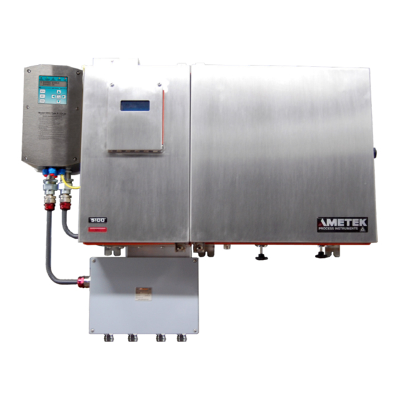
5100HD GAS ANALYZER 5100HD Zone 1 – X-Purge The AMETEK 5100HD TDLAS gas analyzer is an extractive system. It is a single laser analyzer. It is comprised of fully enclosed optics, electronics, sample handling and built-in verification. The unit is designed for outdoor installation and is certified for worldwide hazardous area locations. -
Page 12: Tunable Diode Laser Spectroscopy Theory
So, by measuring the intensity of the laser both be- fore and after absorption by the analyte, the number of analyte molecules in the sample can be deter- mined since all of the other terms in the equation are constant. 1-2 | 5100HD Zone 1 – X-Purge... -
Page 13: Components
Components The 5100HD consists of three distinct modular components: • Electronics Enclosure/User Interface • Customer Connection Box • Sampling System Electronics Enclosure The electronics enclosure houses the electronics, display, and moisture reference cell and is made of stainless steel and built to withstand harsh environments (IP65). -
Page 14: User Interface
Customer Connection Box The customer connection box is a separate enclosure that houses the terminal strip which provides customer I/O, communication and relay alarm connectivity, the RJ45 Ethernet connector, and the power mains supply. 1-4 | 5100HD Zone 1 – X-Purge... -
Page 15: Sampling System
Liquid Separator • Cell Temperature Sensor • Heater The sample inlet port, liquid filter drain and the exhaust port are located on the side for the model 5100HD. Sample Cell The sample cell consists of : • Sample tube •... -
Page 16: Detector
The sample flows from the inlet thru a Genie filter where any liquid condensate is removed. The liquid removed flows down the drain vent connection on the side of the 5100HD. The gas sample then flows thru the sample cell. Cell pressure and temperature are monitored using pressure and temperature sensors respectively. -
Page 17: Laser Line Locking And Built-In Verification
Built-in verification External calibration is time consuming, especially for polar species like water with long equilibration times. The 5100HD uses a sealed reference cell (containing moisture vapor in a buffer gas that does not absorb in the spectral range of interest) for quick analyzer verification. The analyzer response is compared to the value of the analyte concentration in the reference cell and the analyzer performance is verified continuously. - Page 18 100 Mbs Ethernet • MQX RTOS and Modbus capability The 5100HD is configured, and the analyzer parameters are set, using the analyzer display and keypad. The 4-line x 20-character VFD provides moisture data, system operating parameters, system messages, and alarm conditions.
-
Page 19: Options
Options Several options are available • Dual cell capability • High temperature oven • Multiple analytes • High temperature sample cell • Herriott (long path length) sample cell • Space-coupled optics Herriott Sample Cell Option This option is recommended for applications that require enhanced performance at low analyte concentrations. -
Page 20: High Temperature Sample Cell Option
High Temperature Sample Cell Option The 5100HD oven enclosure is capable of maintaining temperatures up to 150C. Some applications demand a high oven temperature to prevent condensation or plugging. For these situations, a special high temperature cell was designed. The main purpose of this sample cell is to thermally isolate the sensitive components (GRIN lens, detector) from these temper- atures. - Page 21 Space-Coupled Option Schematic Overview 1-11...
- Page 22 This page intentionally left blank. 1-12 | 5100HD Zone 1 – X-Purge...
-
Page 23: Specifications
SPECIFICATIONS All specifications subject to change without notice. NOTE Parameter Specification Depends on analyte and availability: H2O: 1854nm (25789JE) CO2: 2004 nm (25834JE) Wavelength 763 nm (25895JE) H2S: 1575 nm (25881JE) CO2 (high range): 1581 nm (25889JE) 25789JE, Class 1m 25834JE, Class 1m Laser Classification 763 nm, Class 3b... - Page 24 O2 in non-absorbing background: +/- 0.1% O2 (1.32 mAU) or 2% of reading, whichever is greater H2S in non-absorbing background: +/- 0.1% H2S (.36 mAU) or 2% of reading, whichever is greater 2-2 | 5100HD Zone 1 – X-Purge...
- Page 25 Parameter Specification H2O: +/- 4 ppmV CO2: +/- 0.1% (10 mAU) 24 hour zero drift +/- 0.1% (1.32 mAU) +/- 0.1% (0.36 mAU) Outputs 4 line x 20 character alphanumeric VF display Fast Ethernet (IEE802.3). RS485 serial port, isolated (supports Modicon MOD- BUS RTU).
- Page 26 Ex II 2 G Ex d e [op pr T4 Gb] px [ia] IIC T3 Gb -20°C < Ta < +50°C Regulatory Compliance ATEX Directive: 2014/34/EU EMC Directive: 2014/30/EU Low Voltage Directive: 2014/35/EU RoHS Directive: 2011/65/EU ATEX Certificate No.: Presafe 15 ATEX 7410X 2-4 | 5100HD Zone 1 – X-Purge...
-
Page 27: Installation And Start-Up
INSTALLATION AND START-UP Read this entire chapter before the installation of the 5100HD Analyz- er. Failure to do so may impair protection against fire, electric shock and injury originally provided by this equipment. Do not use this analyzer in a manner not specified in this manual. -
Page 28: Analyzer Requirements
Analyzer Requirements Location The 5100HD Analyzer is wall-mounted; ensure that there is adequate clearance when mounting and select a readily accessible position for the analyzer to allow for routine maintenance. The location should be free from excessive vibration and the ambient temperature should be -20 °C to 50 °C (-4 °F to 122 °F) without external heating or cooling. -
Page 29: Dimensions
Dimensions 5100HD (Doors Closed): 26.5” High x 32.7” Wide x 11.9 “ Deep 57.3 cm High x 83.1 cm Wide x 30.2 cm deep Installation and Start-Up... -
Page 30: Wiring
Keep shields as short as possible. Ground Stud Method Connect all cable shields for the conduit entry hole to the grounding stud closest to the conduit entry hole. 3-4 | 5100HD Zone 1 – X-Purge... - Page 31 The 5100HD analyzer supports 120 or 240 VAC, 50/60 Hz or 24 VDC. NOTE Connections to the 5100HD are made at the power entry terminal block. It is located in the customer connection box. • Remove the cover of the customer connection box by removing the screws holding it in place and lifting the cover upward and away from the box.
- Page 32 Mains supply connections to the terminal block are as follows: Line Line connection Neutral Neutral connection (USA) Ground Ground connections The 5100HD must be ordered for either 120 VAC or 240 VAC since the oven heater is voltage-specific. 3-6 | 5100HD Zone 1 – X-Purge...
-
Page 33: Analyzer Installation
Secondary process seals must be used on all conduit entry points at the customer connection box to prevent gas/liquids from venting to nonclassified locations. Sample Pressure Requirements AMETEK recommends pressure settings between -4.5 and 10 PSIG. Minimum input pressure: -4.5 PSIG (-31.3 kPa) (10.2 PSIA) -
Page 34: Gas Connections
Locate the analyzer as close as possible to the sample source and install a main process shut-off valve at the sample tap. All connections to the 5100HD are made using 1/4”tubing (6mm for metric option) compres- sion fittings. These fittings are located on the right side of the system enclosure. - Page 35 A pre-filter is recommended to prevent liquids and particulates from entering the analyzer. The 5100HD includes a membrane filter, but this should be considered the last resort protection for the sample cell. An upstream membrane filter should be installed if there is a chance of liquids and/or particulates being present in the sample gas.
-
Page 36: I/O, Communication, And Alarm Relay Connections
Disconnect the power from the analyzer before wiring to the customer connection box. Open the cover on the customer connection box by removing the screws that hold the cover in place. Lift upward and pull away from the box. 3-10 | 5100HD Zone 1 – X-Purge... -
Page 37: I/O Signals
I/O Signals Installation and Start-Up 3-11... -
Page 38: Current Loop Output Connection
Connect the negative (–) side of the power supply to the LOOP – ter- minal. See the following figure: For a 5100HD with two analytes, the above connections are made for loop #2 (second analyte) by using the terminals marked LOOP2 +, LOOP2 -, VDC Output2 +, and VDC Output2 -. -
Page 39: Analog Input - Voltage/Current
Analog Input – Voltage/Current Current Input • On the analog board find Header J2, place jumpers between Pins 3 and 5, and between Pins 4 and 6. See the following figure. Connect the positive (+) input to the Current Input + terminal, and the negative (-) input to the Current Input –... -
Page 40: Rs-485 Communication Connection
The RS-485 uses a 2-wire connection: 2-Wire Termination Resistor: The 5100HD is equipped with a termination resistor that can be used for the last unit on the network. Jumper J7 on the MCU board allows you to place a 120-Ohm termination resistor into the RS-485 circuit. See the fol- lowing figure. -
Page 41: Relay Alarms
Relay Alarms There is (1) relay alarm available for the 5100HD. The relay is configured in the software. The settings available for the alarms are: Disable, Concen- tration, Data Valid, System Alarm, and Normally Open/Normally Closed (NO/NC). Disconnect the power from the analyzer and remove the cover on the customer connection box by removing the screws that hold the cover in place. -
Page 42: Ethernet Cable Connections
Ethernet Cable Connections When using the Ethernet interface on the 5100HD, the minimum require- ment for the Ethernet cable is a CAT 5e (maximum 100 m) cable to connect the analyzer to the network. The maximum distance between the ana- lyzer and the hub is 100 m. -
Page 43: User Interface
User Interface Overview of Keypad The Model 5100HD keypad is used to access menus, sub-menus and system values, and to set-up analyzer parameters. Press ENTER to access the menus. CALIB Used to define on-demand calibration settings. ALARM Used to define alarm output settings. -
Page 44: Overview Of Display
Sample cell pressure and temperature (or alarm if an alarm exists) There is also a series of blips after the “status” message (Sampling ..) that repeat to indicate the analyzer is functioning. 3-18 | 5100HD Zone 1 – X-Purge... -
Page 45: Initial Start-Up
Initial Start-Up Open the main sample shutoff valve at the source. AMETEK recommends you adjust the sample inlet pressure to be- tween -4.5 PSIG and 10 PSIG. Maximum inlet pressure is 10 PSIG. Damage can occur if higher pressures are introduced into the analyzer. - Page 46 This page intentionally left blank. 3-20 | 5100HD Zone 1 – X-Purge...
-
Page 47: User Interface
USER INTERFACE The user interface consists of the display screen on the front of the 5100HD Analyzer and the keypad. Use the arrow keys, BKSP , ENTER, SPACE, numbers, and period to set the parameters for your analyzer. Figure 4-1a. -
Page 48: 5100Hd Analyzer Menu Map
Low Limit Concentration* System Alarm Test NO/NC Normally Open Normally Closed ANALOG Max Conc Concentration* RANGE Min Conc Concentration* *Indicates a value must be entered. Figure 4-2. Menu map for the 5100HD Analyzer. 4-2 | 5100HD Zone 1 – X-Purge... - Page 49 Modbus Slave Address Address* TEST/CONFIG Baud Rate 9600 19200 Parity None Even Time out (ms) Time* Clock Year Year* Month Month * Day* Hour Hour* Minute Minute* Second Second* Press Units psia Temp Units Celcius Fahrenheit System Test Test Relay Relay 1 Close Open...
- Page 50 C dew F High Pressure Transmitter Pressure* Low Pressure Pressure* Secondary Unit ppmV ppmW lbs/mmsct mg/nm3 Fixed Pressure Pressure* Transmitter High Pressure Pressure* Low Pressure Pressure* Secondary Unit ppmV ppmW lbs/mmsct mg/nm3 4-4 | 5100HD Zone 1 – X-Purge...
-
Page 51: Alarm Menu
Alarm Menu The Alarm Key defines alarm settings for each of the 4 relays available. Relay 1 Disable ALARM Analyte Conc High Limit Concentration* Data Valid Low Limit Concentration* System Alarm Test NO/NC Normally Open Normally Closed Relay 2 Disable Analyte Conc High Limit Concentration*... - Page 52 Select this function to trigger an alarm when the system malfunctions. Test Select this function to test the relay alarm settings. NO/NC Select this function to define the default relay position. NC = Normally Closed NO = Normally Open 4-6 | 5100HD Zone 1 – X-Purge...
-
Page 53: Analog Range Menu
Analog Range Menu The Analog Range key defines your 4–20 mA output setting. Use this set- ting to scale the 4–20 mA output. The 4–20 mA output is proportional to the readings. ANALOG MAX CONCENTRATION RANGE MIN CONCENTRATION Main menu for Analog Range key. Max Concentration Enter the reading equivalent to 20 mA. -
Page 54: Test Config Menu
Enter the time out in milliseconds. Modbus interface parameters must be set up to establish communication. Use the Modbus registers to obtain specific input/output data. Modbus Registers can be found at the end of this chapter. NOTE 4-8 | 5100HD Zone 1 – X-Purge... -
Page 55: Clock
Clock Use the Clock function to set the clock on your analyzer. Year Enter Year* CLOCK Month Enter Month* Enter Day* Hour Enter Hour* Minute Enter Minutes* Enter Seconds* Menu for the Clock key. Year Select Year and enter the 4-digit value for the year. Month Select Month and enter the numerical value for the month. -
Page 56: Press Display Units
Use the Temp Disply Units function to select the unit of temperature for the cell to display on the user interface LED when sampling. Select either Celsius (°C) or Fahrenheit (°F). Celsius Temp Disply Units Fahrenheit Menu for the Temperature Display Unit key. 4-10 | 5100HD Zone 1 – X-Purge... -
Page 57: System Test
System Test Use the System Test Key to perform tests on various components of the analyzer. SYSTEM Close TEST RELAYS Relay 1 TEST Open Close Relay 2 Open Close Relay 3 Open Close Relay 4 Open 4 mA TEST ANALOG 12 mA OUTPUT 20 mA... -
Page 58: Network
Network The Network Key enables the 5100HD Analyzer to communicate over an Ethernet network to view data, diagnostics, or backing up/restoring the analyzer configuration. Enable NETWORK NETWORK* Disable Enable DHCP* Disable IP ADDRESS* SUBNET* GATEWAY* Menu for the Network key. -
Page 59: Background Gas
Background Gas This selection allows for the proper background gas to be set. It is criti- cal that the background is chosen to represent the actual process gas as closely as possible, The background gas is typically chosen at the factory during calibration to ensure the best accuracy, based on the customer ap- plication data. -
Page 60: Zero And Span Check Menu And Functions
To begin, the analyzer should be in normal operating mode, and sam- pling. Press the ENTER key, and the main menu selections will appear on the display: 4-14 | 5100HD Zone 1 – X-Purge... - Page 61 Scroll down to the “Span/Zero Check” menu selection using the down- arrow key: Press ENTER to activate this selection. User Interface 4-15...
- Page 62 The following screen will be displayed: To perform a Span Check, scroll to that selection and press ENTER. The following screen will be displayed (for H2O in this example): 4-16 | 5100HD Zone 1 – X-Purge...
- Page 63 If you do not want to perform the span, press the NO key. To proceed with the span, press the YES key. To change the target value to match the applied analyte concentration, press the enter key. The screen below will appear, prompting you for the new value.
- Page 64 The software will perform the span automatically once “123” is keyed. If the password is incorrect, the software will display the message “Incorrect Passcode”. After spanning, the analyzer will return to the “Span/Zero Check” screen. 4-18 | 5100HD Zone 1 – X-Purge...
- Page 65 To perform the Zero Check, the steps are the same, beginning with select- ing “Zero Check”. The following screen appears: Press “YES” to proceed as for the span. User Interface 4-19...
-
Page 66: Modbus Registers
Pressure and Temp Compensation: int16 0=none, 1=pressure, 2=temperature, 3=both uint Bit-Mapped System Alarms uint Bit-Mapped System Alarms uint Bit-Mapped System Alarms uint Bit-Mapped Concentration Alarms System Status: int16 0=everything OK, Not 0=something wrong 4-20 | 5100HD Zone 1 – X-Purge... - Page 67 Data Type Description MB Starting MB Reg Size Regs char[20] Analyte 1 Name float Analyte1 Concentration float Analyte 1 Band High-Limit Band 1 float Analyte 1 Band Low-Limit Band 1 float Analyte 1 Band High-Limit Band 2 float Analyte 1 Band Low-Limit Band 2 float Analyte 1 Band High-Limit Band 3 float...
- Page 68 High End of Range becomes 22 mA; uint16 Output Ratio becomes 1 If Low fault (1) AND in 4-20 mode (ANAOUT2T=0) Low End of Range becomes 3 mA Output Ratio becomes 0 uint16 Relay 1: 0=open, 1=closed 4-22 | 5100HD Zone 1 – X-Purge...
- Page 69 Data Type Description MB Starting MB Reg Size Regs Relay 1 Delay uint16 Holds the relay output for this set amount of time. Relay 1 Function: uint16 0=disabled, 1=concentration, 3=data valid, 4=system alarm Relay 1 Source uint16 The source parameter number used to evalu- ate the relay function.
- Page 70 User Analog Input Fixed Substitute Value float RTD2 (Reference Cell Temperature) float PRESX1 Analog Input Filtered Value float Pressure Transducer 1 Scale float Pressure Transducer 1 Offset float Minimum Concentration float Maximum Concentration float Heater Set Point 4-24 | 5100HD Zone 1 – X-Purge...
-
Page 71: Alarm Messages
Alarm Messages Condition Alarm Message Causes Tec temperature high “TEC Hi Limit Alrm” Laser temperature is above the setpoint Tec temperature low “TEC Lo Limit Alrm” Laser temperature is below the setpoint Cell temperature high “Cell Hi Limit Alrm” Sample cell temperature is above the setpoint Cell temperature low “Cell Lo Limit Alrm”... - Page 72 This page intentionally left blank. 4-26 | 5100HD Zone 1 – X-Purge...
-
Page 73: Maintenance
SUBSTITUTION OF RLY1 MAY IMPAIR SUITABILITY FOR USE IN HAZARDOUS AREAS: Replace only with the same type – AMETEK part number 25869JE. EXPLOSION HAZARD: Do not remove or replace components unless power has been discon- nected or the area is known to be free of ignitable concentrations of flammable gases or vapors. -
Page 74: Cleaning
The battery on the MCU board powers the analyzer clock when the main analyzer AC power is not connected. The clock’s primary function is to timestamp the Alarm Log entries. The AMETEK part number for one bat- tery is 301-0382. - Page 75 Close the analyzer enclosure doors and secure them with their latches to allow the analyzer to warm up to operating temperature and stabi- lize. Check the System Time and system Date (System screen, SETUP menu) and set them to the current time and date. Maintenance...
-
Page 76: Changing Out Replaceable Parts
formed only by qualified personnel who have been properly trained by NOTE AMETEK. AMETEK recommends reading the entire procedure before starting maintenance. Supplies and parts required for maintenance: • Phillips head screwdriver • 3 mm and 4.5 mm hex head wrenches, 9/16" wrench, adjustable wrench •... -
Page 77: Cleaning And Replacing Parts In The Standard Cell
Cleaning and Replacing Parts in the Standard Cell This procedure discusses cleaning and replacing parts in the standard Dual-Pass Sample Cell, used on Single Laser 5100HD TDLAS Analyzers. For other Sample Cells that can be used with this analyzer (listed below), refer to a separate Manual Supplement for instructions on how to clean and replace parts. - Page 78 Sample Cell to the Detector Block (Cell Mounting Plate) inside the Oven. Do not remove or loosen the four (4) screws that secure the Cell Mounting Plate to the Oven wall (see Figure 2). NOTE 5-6 | 5100HD Zone 1 – X-Purge...
- Page 79 c. Remove the two (2) Cell Mounting Clamp screws and its bracket. The Cell RTD will disengage from the clamp, but remain in the Oven. While holding the Cell with one hand, carefully guide the Cell and its connected wires (from the Electronics Enclosure) out of the Oven.
- Page 80 Inspect the interior of the Sample Cell for particulates or damage, and clean it and the o-ring groove with reagent-grade acetone fol- lowed by a rinse with pharmaceutical-grade distilled water. Allow all components to dry thoroughly before reassembling. 5-8 | 5100HD Zone 1 – X-Purge...
- Page 81 Figure 3. Standard Sample Cell assembly. Maintenance...
- Page 82 Install one (1) new 127 o-ring (PN 42827JE) in the Cell Body (Fig- ure 5). Figure 5. Sample Cell, Mirror installed, gold-plated surface facing into Cell (with gold-plated Mirror – gold-plated side side of Mirror shown shown. at right). 5-10 | 5100HD Zone 1 – X-Purge...
- Page 83 While holding the Mirror (PN 16052JE) by its outer edge, install the Mirror (gold/mirrored surface facing inside) in the Cell. Carefully replace the Bottom Cap (with Compression Spring in- stalled) on the Cell Body, taking extreme care to ensure the Mirror does not drop out and to avoid losing the Compression Spring when joining the parts.
- Page 84 “Zero and Span Check Functions” in Chapter 4 of this manual. 10. Open the Sample Drain valve (if applicable). Open the Sample Outlet valve. Open the Sample Inlet valve. 11. Adjust the flow and pressure rates for normal operation. The procedure is complete. 5-12 | 5100HD Zone 1 – X-Purge...
-
Page 85: Cleaning And Replacing Parts In The Particulate Filter (If Equipped)
However, if it has been determined that the Filter has become contaminated or plugged, the Filter will need to be cleaned or have its internal parts replaced. Therefore, AMETEK recom- mends inspecting the Filter frequently (e.g., weekly) for new installations, to determine how long it typically takes for the filter to become contami- nated. - Page 86 Inspect the Filter Cap and clean it and the o-ring groove with reagent- grade acetone followed by a rinse with pharmaceutical-grade distilled water. Allow all components to dry thoroughly before reassembling. 5-14 | 5100HD Zone 1 – X-Purge...
- Page 87 5. Install the new Membrane Filter and o-ring: Some Membrane Replacement Kits include a new o-ring; but some do not. If your Membrane Replacement Kit does not include an o-ring, re-use the original one. In this case, clean the o-ring to remove any contaminants before replacing it.
-
Page 88: Spare Parts For The 5100Hd Analyzer
Spare Parts for the 5100HD Analyzer Use the following AMETEK Part Numbers to order replacement Sample Cell or Particulate Filter parts for the 5100HD Analyzer. Sample Cell Spare Parts Part No. Description 16052JE Mirror, 1-inch Diameter 31860JE Compression Spring, SS... -
Page 89: Sample System Leak Check
5. Connect a supply of compressed air or nitrogen to the shut-off valve on the Inlet port. Ensure the gas and associated tubing is clean and dry (AMETEK recommends using a compressed gas cylinder – do not use house air as it can contain high levels of moisture). - Page 90 Drain port and replace the Drain tubing. Slowly open all valves on the analyzer (Inlet, Exhaust, and Drain – if used). 10. Return the analyzer to its normal flow rate. The procedure is complete. 5-18 | 5100HD Zone 1 – X-Purge...
-
Page 91: X-Purge
X-PURGE Purge Startup Procedure The AMETEK 5100HD Zone 1 – X-Purge has an enclosure protection system that controls power to the analyzer (X-Purge). All enclosure pro- tection systems have some alarm or indicator to alert the user upon loss of protective pressure. In either case, it is wise to make sure the purge system is functional before turning on power to the analyzer. -
Page 92: Electronic Power Control Unit (Epcu) Response
Safe Enclosure Pressure (>.63 mbar) REF: Rapid Exchange Flow RET: Rapid Exchange Time complete (4 or 8 minutes)¹ EP ON: Enclosure Power ON HEP: High Enclosure Pressure (>7 mbar) ALARM: EPCU relay engaged when no fault present A-2 | 5100HD Zone 1 – X-Purge... - Page 93 STATE EPCU ON EP ON ALARM Power Off EPCU Warmed Up Safe Pressure Set Rapid Exchange Initiated² Enclosure Power On High Enclosure Pressure ¹Rapid exchange time can be 4 minutes at 340 lpm or 8 minutes at 141 lpm depending on the selected mode. ²Rapid exchange can be initiated manually by pressing the START/SET key or automatically depending on the selected mode.
-
Page 94: X-Purge Operating Instructions
Do not exceed 1.5” wc (3.75 mbar). If air is not exhausting at the vent, check for any obstructions or im- proper installation. The system is ready to operate. A-4 | 5100HD Zone 1 – X-Purge... -
Page 95: Operation Of The 6000 Series System (Gas Hazardous Location
Operation of the 6000 series system (gas hazardous location): • Follow the “Set-up procedures for the 6000 series system”. • Seal the enclosure. • Set the pressure to a value above a minimum of 0.25” wc (.625 mbar) or the set value from previous user input (cannot be below 0.25” wc). •... -
Page 96: Bypass Instructions
Bypass Instructions Bypass Password: • Seal and purge the enclosure. • Only when the enclosure is safely purged can the bypass control be activated. • Using the 6000 Series controller follow the directions: A-6 | 5100HD Zone 1 – X-Purge... -
Page 97: Hardware Details
Hardware Details Type X-Purge If a Type X-Purge system is installed, the inlet for instrument purge air is located on the purge controller. Dry instrument air pressure should not exceed 8 kg/cm² (120 psi) and should be regulated between 4–5 kg/cm² (60–80 psig). -
Page 98: 6000 Series Control Unit
¾” NPT male pipe (explosion proof seals required) I.S. Input connections: Terminal connection inside 6000 series unit Materials Enclosure: 316L (UNS31603) Stainless Steel Manifold valve: Anodized 6082 Aluminum Fittings: 316L (UNS31603) Stainless Steel A-8 | 5100HD Zone 1 – X-Purge... -
Page 99: Epv6000 Relief Vent
EPV6000 Relief Vent Flow rate measurement: Flow rate is measured in increments: 5, 12, 20, 30 SCFM (141 l/min, 340 l/min, 565 l/min, 850 l/min) Protection Class: Mounting fitting Type 4X, IP66 Weight: 2 lb Power connections: M12 (V1) pin connector (mating con- nector with cable comes with vent for connection to the control unit);... - Page 100 This page intentionally left blank. A-10 | 5100HD Zone 1 – X-Purge...
Need help?
Do you have a question about the 5100HD and is the answer not in the manual?
Questions and answers