Table of Contents
Advertisement
Quick Links
Advertisement
Table of Contents

Related Manuals for Ametek 5830


Summary of Contents for Ametek 5830
- Page 1 USER MANUAL 5830 Moisture Analyzer PN 583054901 Rev YA...
- Page 2 AMETEK Process Instruments assumes no responsibility or liability for any errors or inaccuracies that may appear in this document. AMETEK Process Instruments is not responsible for any infringement of patents or other rights of third parties that may result from the use of this document. The content of this document is furnished for informational purposes only, is subject to change without notice, and does not represent a commitment or guaranty by AMETEK Process Instruments.
-
Page 3: Table Of Contents
Contents Safety Notes ..............................vii Electrical Safety ............................viii Grounding ..............................viii Sample Gas ............................... viii Personnel and Equipment Safety Information................ix Special Warnings and Information ......................xi Equipment Used in Class I, Division 2 Hazardous Locations ..........xi Dryer Warning .............................xi Electromagnetic Compatibility (EMC) ....................xii Warning Labels ............................ - Page 4 Initial Start-Up ............................2-20 Dry-Down Period ......................... 2-20 Procedure for Speeding up the Dry Down Period ............2-21 Performing an Initial Zero ......................2-21 Configuring the 5830 Analyzer for Serial Communications ..........2-22 Protocol ............................2-22 Special Addresses ........................2-24 Address $F0 ...........................2-24 Defined Commands (Master to Slave) ..................
- Page 5 Verify Schedule ........................3-12 Production Codes .........................3-13 Moisture Unit ........................3-13 System Test ..........................3-14 Working From the 5830 Configurator Software ............... 3-15 Configurator Software Installation ..................3-15 Configuring the 5830 ......................... 3-16 Working From the General Tab ..................3-16 Saving Analyzer Configuration Settings ................3-18 Working From the Device Communication Tab ............3-19...
- Page 6 Removing the Dryers ....................4-15 Installing the New Dryer .....................4-16 Maintenance of the Electronics Module ..................4-17 Removing the Electronics Module From the 5830 ............4-17 Tools Required ..........................4-17 Procedure for Removing the Electronics Module ............4-17 Proportional Solenoid Valve (PSV) Board ................4-19 Analog Interface PCB ........................
-
Page 7: Safety Notes
Burn hazard. Hot surface. Do not touch, allow to cool before servicing. Read this manual before beginning the installation and operation of the 5830 Analyzer. Failure to do so, and or use of the equipment in a manner not speci- fied in this manual or accompanying documents, may impair the protection against fire, electrical shock and injury originally provided by this equipment. -
Page 8: Electrical Safety
Check the sample line and all connections for leaks before powering up. Consult plant safety personnel for appropriate exhaust venting guidelines for specific sample gas type. PN 583054901, Rev YA viii | 5830 Moisture Analyzer... -
Page 9: Personnel And Equipment Safety Information
Personnel and Equipment Safety Information This section describes important safety information to avoid personal injury and dam- age to the equipment while installing, operating, maintaining, or servicing the equip- ment. All safety regulations, standards, and procedures at the analyzer location must be followed. - Page 10 Do Not Operate in Explosive Atmosphere To avoid injury or fire hazard, do not operate this product in an explosive atmosphere unless you have purchased options that are specifically designed for these environments. PN 583054901, Rev YA x | 5830 Moisture Analyzer...
-
Page 11: Special Warnings And Information
AVERTISSEMENT – Risque d’explosion – La substitution de composants peut rendre ce materiel inacceptable pour les emplacements de Classe I, Division 2. Refer to the “Safety Critical Components” in the 5830 Analyzer Replacement Parts list in Chapter 4 of this manual. -
Page 12: Electromagnetic Compatibility (Emc)
The various configurations of the 5830 Moisture Analyzer should not produce, or fall victim to, electro- magnetic disturbances as specified in the European Union’s EMC Directive. Strict compliance to the EMC Directive requires that certain installation techniques and wiring practices are used to prevent or minimize erratic behavior of the Analyzer or its electronic neighbors. -
Page 13: Warning Labels
Achtung – Heiße Oberfläche Environmental Information – WEEE This AMETEK product contains materials that can be reclaimed and recycled. In some cases the product may contain materials known to be hazardous to the environ- ment or human health. In order to prevent the release of harmful substances into the environment and to conserve our natural resources, AMETEK recommends that you arrange to recycle this product when it reaches its “end of life. - Page 14 This page intentionally left blank. PN 583054901, Rev YA xiv | 5830 Moisture Analyzer...
-
Page 15: Overview
Overview The 5830 Moisture Analyzer reliably measures low concentrations of moisture in high purity gases at concentrations down to 20 parts-per-billion by volume (PPBV), using a quartz crystal microbalance (QCM) sensor. The calibrated range of the analyzer is 0 to 100 PPMV with a trend indication for measured concen- trations to 1000 PPMV. -
Page 16: Controller/Communications
One (1) RS-232 or one (1) RS-485 serial interface provides communication between the analyzer and your recording or data acquisition equipment. The 5830 Moisture Analyzer is configured, and analyzer parameters are set, by using either the analyzer display, keypad and function keys, or using an exter- nal PC. -
Page 17: Contact Closure Signals
Contact Closure Signals The analyzer provides the following contact closure signals. System Alarm Activates (contact opens) when a condition exists that makes analyzer output questionable. Such conditions include: • Cell Temperature alarm • Zero error • Battery alarm Moisture Concentration Alarm Activates (contact opens) when a moisture concentration exceeds the pro- grammed alarm levels. -
Page 18: Moisture Sensor
Moisture Sensor Quartz Crystal Microbalance (QCM) The 5830 Moisture Analyzer uses a quartz crystal microbalance Sensor to mea- sure water vapor concentration. This is a piezoelectric device that is capable of extremely sensitive mass measurement. To make the QCM sensitive to water vapor the surface is coated with a thin film of hygroscopic material. -
Page 19: Gas Flow
Gas Flow Sample System The 5830 Moisture Analyzer sample system enables the analyzer to make reliable water vapor measurements at concentrations down to 20 PPBV. The Sample Sys- tem serves several purposes: • It controls the sample conditions at the Sensor assembly (e.g., flow rate, temperature, pressure). -
Page 20: Sample Flow
Sample Flow Normal operation of the 5830 Moisture Analyzer uses an internal bypass, which increases the response speed of the system. However, the 5830 is ca- pable of running in a gas-saver mode as well, which allows the analyzer to run on a sample volume of approximately 150 SCCM. -
Page 21: Solenoid Valves
The two-way solenoid valve (SV5) is used to isolate the dryer from moisture when power is removed from the analyzer. In normal op- eration of the 5830, the analyzer continuously cycles between the Sample- and Dry-Reference gas streams. This switching action modulates the water vapor concentration to which the Sensor is exposed. -
Page 22: Zero Gas Module
Normally, the magnitude of these offsets is relatively small—less than the equivalent of 0.1 PPMV. However, as the intention of the 5830 Mois- ture Analyzer is to have a detection limit of only 0.02 PPMV, these minor effects must be accurately determined and removed from the moisture measurement. -
Page 23: Verifying The Analyzer
During the Verification operation, a new span factor is calcu- lated for the Sensor, and this value is then applied for all subsequent readings. AMETEK recommends performing a Verification cycle monthly. How- ever, no Verification cycle should be performed during the startup of the analyzer. -
Page 24: Dew/Frost Point Measurements
Dew point values are calculated from the moisture concentration measure- ments (PPMV) and the sample or process pressure. For temperatures below 0 °C, the 5830 uses equations to determine the water vapor pressure over ice, rather than over super-cooled water. Thus, the 5830 reports a frost-point tem- perature consistent with the physical form of the condensed phase in a real process stream. -
Page 25: Installation And Start-Up
Installation and Start-Up Safety Considerations This chapter contains information about the installation and setup of the 5830 Moisture Analyzer. Before beginning the installation of the analyzer and before powering it up, review and follow all safety information following the Table of Contents near the beginning of this manual. - Page 26 Analyzer Requirements Space Requirements The 5830 Moisture Analyzer requires an area 48 cm wide x 13 cm high x 42 cm deep (19" x 5.25" x 16.5") plus rear clearance for analyzer connections and proper ventilation (Figures 2-11.1, 2-11.2, and 2-11.3). It should be located as close to the sample tap as possible.
- Page 27 PO W ER SIGN AL Pr essur e In stru m en t Air 70 - 1 00 PSIG Figures 2-1.2. 5830 Analyzer dimensions, front (top) and rear (bottom). Figures 2-1.3. 5830 Analyzer dimensions, top and sides. Installation and Start-Up...
-
Page 28: Unpacking And Inspecting The Equipment
Unpacking and Inspecting the Equipment Remove any packing material from the 5830 Moisture Analyzer shipping crate. Check for damage. If equipment is damaged, notify the carrier and contact AMETEK (https://www.ametekpi.com/customersupport/aftermarket) imme- diately if parts are missing or damage is found, and to verify if damaged parts will require replacement prior to safely installing and operating the analyzer/ equipment. -
Page 29: Electrical Requirements
Electrical Requirements The 5830 Analyzer must be installed in a general purpose area. It does not have an On/Off power switch so power must be applied through a circuit breaker switch at the AC source. General Purpose Installation: • Power connection can be made using the supplied power cord(s) termi- nated with a locally approved wall socket plug, or •... -
Page 30: Sample Temperature And Pressure Requirements
5–20 PSIG (34.5–138 kPa) Nitrogen 5–20 PSIG (34.5–138 kPa) Oxygen 5–20 PSIG (34.5–138 kPa) Argon 7–20 PSIG (48.3–138 kPa) If necessary, a UHP pressure regulator can be installed at the main process shut-off valve. 2-6 | 5830 Moisture Analyzer PN 583054901, Rev YA... -
Page 31: Analyzer Installation
Optimal results are obtained with the sample line maintained at 60 °C. Recommended Sample Inlet fitting tubing is 1/4-inch OD, electro pol- ished 316L VAR stainless steel (AMETEK Part No. 257707002 or equiva- lent). •... -
Page 32: Rear Panel Connections And Interface Board
12 Analog Output 4–20 mA output to user recording equipment. Wiring supplied by user. 13 Alarm Contacts Connections for: Data Valid, Concentration Alarm, and System Alarm. Wiring supplied by user. 2-8 | 5830 Moisture Analyzer PN 583054901, Rev YA... - Page 33 Exhaust Sample In RS-232 20-50 PSIG Atmospheric Pressure POW ER SI GNAL Instrument Air 70-100 PSIG Figure 2-2. 5830 Rear Panel connections and inside of dryer compartment. LINE VOLTAGE RS-485 TERMINATOR Line Voltage Selector FUSE RS-485 ANALOG OUTPUT DATA CONC...
-
Page 34: Installing The Dryers
Installing the Dryers Prior to operating the 5830 Analyzer, the dryers must be installed. Two (2) dryers have been supplied with this analyzer. Make sure that you have the two (2) new dryers, and four (4) new VCR gaskets available before beginning installation. - Page 35 5. Using two (2) of the dryer mounting screws, secure the dryer in the top (Sample System Dryer) position (Figure 2-4.2). 6. Working quickly, install a new 1/8-inch VCR gasket in both of the fittings, and tighten the two (2) VCR nuts over the fittings until they are finger tight. 7.
-
Page 36: Gas Connections
D RYER C O M PARTM EN T C O VER Exhaust Sample In RS-232 20-50 PSIG Atmospheric Pressure POWER SIGNAL Instrument Air 70-100 PSIG Figure 2-5. 5830 Moisture Analyzer gas connections. 2-12 | 5830 Moisture Analyzer PN 583054901, Rev YA... -
Page 37: Electrical Connections
If qualified service personnel are not available, contact AMETEK Service. Voltage Selection The 5830 Analyzer comes from the factory set to operate on 120 VAC. If you must switch the setting to 240 VAC (or back to the 120 VAC setting), follow the procedure below. -
Page 38: Power Connection
If the new cord is a smaller diameter than the original, consider using the alternate bushing that is included with the European cord. Ensure that the power cord does not slip when pulled or pushed from the outside. 2-14 | 5830 Moisture Analyzer PN 583054901, Rev YA... - Page 39 ANALOG OUTPUT DATA CONC SYSTEM Terminator VALID ALARM ALARM Fuse Receptacle RS-485 Power Connector Serial Port Alarm & Alert Contacts Analog Output Figure 2-9. Communication connections on the 5830 Analyzer Interface board. Installation and Start-Up 2-15 PN 583054901, Rev YA...
-
Page 40: Communication Connections
RS-232 to RS-485 Conversion for Host PC. Converter and Power Supply are not suitable for use in hazardous locations. Refer to Chapter 4 for replacement part numbers. 5. Replace the Terminal Cover. 2-16 | 5830 Moisture Analyzer PN 583054901, Rev YA... -
Page 41: Signal Connections (4-20 Ma)
Signal Connections (4–20 mA) 100 to 500 ohms Figure 2-11.1. Self-powered 4–20 mA output Meter connections. 100 to 500 ohms Supply 24 Volts Figure 2-11.2. Externally powered Meter 4–20 mA output connections. Installation and Start-Up 2-17 PN 583054901, Rev YA... -
Page 42: Overview Of The Keypad
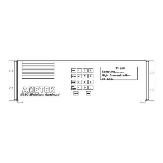
Overview of the Keypad The 5830 Moisture Analyzer keypad (Figure 2-12) is used to access menus and sub-menus and system values for the function keys, and to configure your analyzer parameters. Zero Alarm FUNCTION Analog KEYS Range Test Config Cancel Enter Figure 2-12. -
Page 43: Overview Of Display
To highlight an item, scroll through the menu items until the small arrowheads point to your choice as shown in Figure 2-13. Up and down arrow symbols dis- played on the right-hand side of the screen indicate that there are more menu items above or below the currently displayed items. -
Page 44: Initial Start-Up
If the concentration value is still decreasing after the initial dry down period, allow additional dry down time. The 5830 Analyzer is now fully operational with factory default configuration of the Analog Output and Concentration Alarms. You are ready to do an initial Zero cycle. -
Page 45: Procedure For Speeding Up The Dry Down Period
Procedure for Speeding up the Dry Down Period To decrease the time required to dry down the 5830 Analyzer: 1. Make all gas connections and apply power to the analyzer. Allow the ana- lyzer to warm up and run with the factory-default settings for a period of 6–12 hours. -
Page 46: Configuring The 5830 Analyzer For Serial Communications
Configuring the 5830 Analyzer for Serial Communications Protocol The protocol used for the 5830 Moisture Analyzer is a master/slave, command/ response communication with the master initiating all transfers. The message format for transfers initiated by the master is illustrated in Figure 2-16. - Page 47 The checksum for a slave response is the modulo 256 sum of all characters pre- ceding the checksum including the response code. The message format for slave responses containing a data field is illustrated in Figure 2-17. Data End Flag Figure 2-17.
-
Page 48: Special Addresses
The commands that can be issued from the master are listed in Figure 2-20. Command Byte Function Echo Bad Command Acknowledge Read Data Not Used Write Data Write Cell EEPROM Quit Zero Analyzer Reset Toggle Test Mode Figure 2-20. Initiate Zero Defined Commands table. 2-24 | 5830 Moisture Analyzer PN 583054901, Rev YA... -
Page 49: Echo (A)
Echo (A) Echo implements a loop back function to test the integrity of the serial com- munication. Any text transmitted by the master is returned. Example: Master: >99ABCDEFG4E[CR] Slave: AABCDEFG1D[CR] Bad Command (B) This command is not recognized by the slave. It will therefore result in a type 01 failure response. -
Page 50: Write Data (H)
Zero cycle is terminated immediately and normal operation resumed. Example: Master: >34QB8[CR] Slave: A[CR] Zero (Z) Initiates a Zero cycle. Example: Master: >34Z??[CR] (Note the use of wildcard in place of checksum) Slave: A[CR] 2-26 | 5830 Moisture Analyzer PN 583054901, Rev YA... -
Page 51: Defined Responses (Slave To Master)
Defined Responses (Slave to Master) There are three (3) possible responses to a communication transfer initiated by the master. These are a Simple Acknowledge, Acknowledge with Data, and a Failure message. Simple Acknowledge If the received command does not require data to be returned, a simple ac- knowledge consisting of an ASCII ‘A’... -
Page 52: Variables Table
Zero schedule parameter Integer ZeroWeekDays Zero schedule parameter Integer ZeroType Zero type(daily,monthly,weekly) Integer 0(daily) Pressure1 Sensor pressure value Float 14.7 psi CellTemp Sensor temperature value Float 60.0 degreeC Figure 2-22.1. Variables Table. 2-28 | 5830 Moisture Analyzer PN 583054901, Rev YA... - Page 53 String 08:45 SystemState Alarm status word Integer 1024 DataState Data ready variable Integer ModelName Analyzer model name String 5830 ReferencePer Current reference period time Integer SamplePer Current sample period time Integer WetFreq Wet frequency reading Float 1234 Hz DryFreq Dry frequency reading...
- Page 54 This page intentionally left blank. 2-30 | 5830 Moisture Analyzer PN 583054901, Rev YA...
-
Page 55: Controller/Interface
Working From the Built-in User Interface The built-in user interface consists of the LCD display screen and keypad on the front of the 5830 Moisture Analyzer. Using a combination of the function keys, numbers, and other characters, you can set the parameters for your ana- lyzer. - Page 56 Test Keypad Open Contacts Test Alarms Close Contacts 4 mA Output Test Analog Figure 3-2. 12 mA Output 20 mA Output Menu Map for 5830 Test Serial Start Moisture Analyzer. Cancel 3-2 | 5830 Moisture Analyzer PN 583054901, Rev YA...
-
Page 57: Zero Key
Enable Select this function to adjust the span after a verify. Disable Select this function to verify without adjusting the span. The 5830 will always adjust the offset after a zero. Zero This function initiates a zero cycle. Controller/Interface PN 583054901, Rev YA... -
Page 58: Alarm Key
Enter the high limit value in moisture units selected. Low Limit Enter the low limit value in moisture units selected. Enable Alarm Select Enable or Disable to activate the moisture concentration alarm relay. 3-4 | 5830 Moisture Analyzer PN 583054901, Rev YA... -
Page 59: Range Key
Range Key Use the Range key to define your 4–20 mA output setting. Use this setting to scale the 4–20 mA output. The 4–20 mA output is propor- tional to the moisture readings. RANGE Enter Maximum Conc Value Enter Figure 3-5. Minimum Conc Value Main Menu, Range key. -
Page 60: Config Key
Enter a value from '1' to '9' . The default is '5' . Back Light Select On or Off. The default is On. Font This is a factory-set parameter that identifies the type used for the display on the analyzer. 3-6 | 5830 Moisture Analyzer PN 583054901, Rev YA... -
Page 61: Communication
Communication Select communication setup. Config Communication Node Enter Address Address 9600 Baud Rate 19200 RS-485 Two Wire Mode Figure 3-6.3. Four Wire optional Communication menu. Node Address Enter the address for RS-485 serial communications (0–240). Address 240 is reserved (see the “Special Addresses” section in Chapter 2 for details). Baud Rate Select the baud rate at which you transfer data (9600 or 19200). -
Page 62: Sample Gas
This list allows you to specify the Sample gas you want to analyze. Figure 3-6.4. Sample Gas menu. Select Gas Press Enter to move to the listing of Sample gases. Scroll up/down the list to select the correct Sample gas. 3-8 | 5830 Moisture Analyzer PN 583054901, Rev YA... - Page 63 Gas K Factor. The Gas K Factor is a parameter used by the Mass Flow Meter in the 5830 to adjust for the molar heat capacities of different gases. Nitrogen is used as the Reference gas for the K factors, and its value is de- fined as 1.000.
-
Page 64: Clock
Select the day of the week from the list. Month Enter the 2-digit value for the month. Hour Enter the value using the 24-hour clock. Minute Enter the 2-digit value for minutes. 3-10 | 5830 Moisture Analyzer PN 583054901, Rev YA... -
Page 65: Zero Schedule
AMETEK recommends performing a Zero every 24 hours for the first month of operation. After this start-up period, the analyzer will have dried down sufficiently to increase the Zeroing interval to 1 week. AMETEK recommends that the duration of the Zero cycle be set to 120 (i.e., 2 hours). Controller/Interface... -
Page 66: Verify Schedule
After this start-up period, the analyzer will have dried down sufficiently to increase the Verification interval to 1 month. AMETEK recommends that the duration of the Verification cycle be set to 60 (i.e., 60 minutes). -
Page 67: Production Codes
Production Codes Use this function to enter the production codes for the Moisture Generator and Reference Dryer. Config Generator Production Codes Reference Figure 3-6.8. Dryer Production Codes menu. Generator The production code for the Moisture Generator is required for proper operation of the analyzer. -
Page 68: System Test
Tests the Analog Output by allowing the user to set outputs to 4, 12, or 20 mA. Test Serial Communications Performs a “loop back” test and reports the result to the display. 3-14 | 5830 Moisture Analyzer PN 583054901, Rev YA... -
Page 69: Working From The 5830 Configurator Software
3. Follow the instructions on the subsequent screens to complete the instal- lation. When you get to the Setup Complete screen, click Finish to com- plete the installation. The default location for the 5830 software is in the AMETEK, Inc. folder. -
Page 70: Configuring The 5830
After initial setup, any changes to the analyzer communications parameters must be made using the Device Communications tab. These changes must be made before you make any changes to the computer serial port settings. 3-16 | 5830 Moisture Analyzer PN 583054901, Rev YA... - Page 71 PC Communications Setup Options Displays information that has been configured from the Serial Port Con- figuration dialog box. Click the Setup button to configure PC Communications. The Serial Port Communication screen opens (Figure 3-8). Figure 3-8. PC Serial Communications setup screen. Port Select the COM port on your computer where the connection to the analyzer is installed.
-
Page 72: Saving Analyzer Configuration Settings
To save all of the settings made on the General tab, click Apply. To save settings and exit the program, click Apply+Exit. To abort changes you have made, click Cancel+Exit. This will close the Con- figurator Software program. 3-18 | 5830 Moisture Analyzer PN 583054901, Rev YA... -
Page 73: Working From The Device Communication Tab
Working From the Device Communication Tab For initial setup of PC communication parameters, use the Setup but- ton on the General tab. Figure 3-9. Device Communication setup screen. Configuring Multiple Analyzers Use the Device Communication tab to set the analyzer’s communication parameters to agree with the PC settings when controlling analyzers in a daisy chain. -
Page 74: Saving Your Settings
To save settings on the Device Communications tab, click Apply. To save settings and exit the program, click Apply+Exit. To abort changes you have made, click Cancel+Exit. This will close the Con- figurator Software program. 3-20 | 5830 Moisture Analyzer PN 583054901, Rev YA... -
Page 75: Working From The Setup Tab
Working From the Setup Tab Use the Setup tab to define analyzer parameters. Figure 3-10. Schedule tab. Select the gas being sampled. Dewpoint Temp – If you select dewpoint temp, the Process Pressure box is activated and you must enter a process pressure parameter in kPa. - Page 76 Check this box to enable the Concentration Alarm. High Limit Enter the high limit for the Concentration Alarm. Low Limit Enter the low limit for the Concentration Alarm. To Save settings on the Setup tab, click Apply. 3-22 | 5830 Moisture Analyzer PN 583054901, Rev YA...
-
Page 77: Working From The Schedule Tab
Adjust Offset check box Checked Check this box to adjust the span after a verify. Not checked Uncheck this box to verify without adjusting the span. The 5830 will always adjust the offset after a zero cycle. Controller/Interface 3-23 PN 583054901, Rev YA... - Page 78 Enter the Verification duration in minutes. The system defaults to the mini- mum time required. Zero Duration Enter the zero duration in minutes. The system defaults to the minimum time required. 3-24 | 5830 Moisture Analyzer PN 583054901, Rev YA...
- Page 79 Scheduled Verification Schedule routine Verifications by clicking the Daily, Weekly, or Monthly button. Never No Verification will be done. Scheduling fields at the bottom of the box are not available. Daily To run a Verification daily, select this option and then enter the time of day (1 through 24) in the Hour field at the bottom of this group.
-
Page 80: Saving Your Settings
To save settings on the Schedule tab, click Apply. To save settings and exit the program, click Apply+Exit. To abort changes you have made, click Cancel+Exit. This will close the Con- figurator Software program. 3-26 | 5830 Moisture Analyzer PN 583054901, Rev YA... -
Page 81: Working From The Status Tab
Working From the Status Tab Use the Status tab to view current readings and the status of the analyzer. Figure 3-13. Status tab. Upload Data Click Upload Data to save data from the analyzer to a file. The Save As screen opens so that you can browse to where you want to save the file. -
Page 82: Working From The Monitor Tab
Working From the Monitor Tab Use the Monitor tab to check on analyzer operation. From this tab you can also collect data from the analyzer. Figure 3-14. Monitor tab. 3-28 | 5830 Moisture Analyzer PN 583054901, Rev YA... -
Page 83: Data Capture
Data Capture The data capture feature allows the user to collect and save analyzer data dis- played on the Monitor tab to an Excel compatible file. Press the On button to start data collection. Specify the file name in the Save As dialog and press the Save button. - Page 84 This page intentionally left blank. 3-30 | 5830 Moisture Analyzer PN 583054901, Rev YA...
-
Page 85: Maintenance And Troubleshooting
The operations in this chapter should be performed only by qualified service personnel experienced in electrical safety techniques. Before working on the 5830 Analyzer, read the entire procedure you will be performing to learn how to safely and properly perform main- tenance or service the analyzer. -
Page 86: Aftermarket Excellence And Long-Term Commitment To Safety And Quality
Scan the QR code or click the link below to request expert Aftermarket support for parts, repairs, service, training, and more: www.ametekpi.com/customersupport/aftermarket 4-2 | 5830 Moisture Analyzer PN 583054901, Rev YA... -
Page 87: 5830 Analyzer Replacement Parts
5830 Analyzer Replacement Parts * Indicates recommended stock spare parts to have on hand. Refer to the Figure number listed for the location of the part. Part Description AMETEK Part No. Figure Battery, Lithium 280750043 4-11 EEPROM, programmed 583067901S —... -
Page 88: Servicing The 3050-Am Analyzer
Servicing the 3050-AM Analyzer Make sure that power has been disconnected from the analyzer before attempting to remove or replace any of the parts. Figure 4-1. 5830 exploded view. 4-4 | 5830 Moisture Analyzer PN 583054901, Rev YA... - Page 89 Zer o Modu le Dryer Pres sure Tra nsducer Fl ow M eter Sensor Figure 4-2. Mo i st ure 5830 sampling system. G enerat o r Figure 4-3. Sensor removal in 5830 PN 583054901, Rev YA Maintenance and Troubleshooting | 4-5...
-
Page 90: Sensor
1. Remove the Analyzer Cover. 2. Remove the cover from the Sample Oven Cover. Facing the front of the 5830 Analyzer, the Sensor is the small PC board with two (2) metal cans in the center of the sample manifold plate (Figure 4-2). -
Page 91: Mass Flow Meter
Removing the Mass Flow Meter 1. Remove the Analyzer Cover. 2. Remove the Sample Oven Cover. Facing the front of the 5830 Analyzer, the Mass Flow Meter is the small black box on the left-hand side of the Sample Oven (Figure 4-2). -
Page 92: Installing The Mass Flow Meter
- 2 pl aces C omp res sion Fittin f ro m Sample Syste m Figure 4-4. 5830 Mass Flow Meter. 4-8 | 5830 Moisture Analyzer PN 583054901, Rev YA... -
Page 93: Moisture Generator
Removing the Moisture Generator 1. Remove the Analyzer Cover from the analyzer. 2. Remove the Sample Oven Cover. Facing the front of the 5830 Analyzer, the Moisture Generator is located left- center on the sample manifold plate, underneath the pressure transducer, between the Flow Meter and the Sen- sor assembly. - Page 94 Plate N ut N ut N ut s Pressure Tra nsducer Cl i p Moist ure Mo unti n g Figure 4-5. G enera to r 5830 Moisture Generator. Brac ket 4-10 | 5830 Moisture Analyzer PN 583054901, Rev YA...
-
Page 95: Installing The New Moisture Generator
4/40 Fl at Head Scre w Pres sure Trans ducer Lock W asher Fl at W asher I n/ O ut connections m ust be hori z onta l Moisture Generator Figure 4-6. Removing the Moisture Generator and pressure Mani f ol d transducer. -
Page 96: Solenoid Valves
6. Using a flat-head screwdriver, remove the screws that hold the valve body to the manifold; set the screws aside. Lift-off the solenoid valve and reserve the O-rings for the replacement solenoid. 4-12 | 5830 Moisture Analyzer PN 583054901, Rev YA... - Page 97 Propor t ional Solenoid 2-Way Solenoid 3-Way Solenoid s Mu st b e re m oved to access solenoid b ehind i Figure 4-7.1. 5830 solenoids. PN 583054901, Rev YA Maintenance and Troubleshooting | 4-13...
-
Page 98: Installing The New Solenoid
Ele ctr i cal C onnect ion 3-Way Solenoid Valve Fla t Washer ( 2) 6/ 32 Fla t H ead Figure 4-7.2. Scr ew ( 2) Lock Washer ( 2) 5830 solenoid replacement. 4-14 | 5830 Moisture Analyzer PN 583054901, Rev YA... -
Page 99: Dryers
( bottom dryer ) Dryer M ount i ng Scre w s (2 ea ch) Dryer Compartment 1/8" VC R G asket Cover (2 ea dryer ) Figure 4-8. 5830 dryers. PN 583054901, Rev YA Maintenance and Troubleshooting | 4-15... -
Page 100: Installing The New Dryer
Installing the New Dryer Minimize the time that the dryer is exposed to the atmosphere after removing the protective caps. AMETEK recommends that the dryer be exposed for less than one (1) minute. 1. Insert the replacement dryer into the dryer port on the analyzer. Use the new VCR gaskets provided with the dryer in each of the fittings. -
Page 101: Maintenance Of The Electronics Module
• Once you remove the Electronics Module from the 5830 Enclosure, you can place it on the 5830 Enclosure as a resting fixture. However, take care not to scratch the 5830 Enclosure with the Electronics Module (a piece of cardboard can be placed under the Electronics Module to protect the enclosure). - Page 102 Ele ct ron ic M odule Pilot Valve Proportional Receptacle Plugs Solenoid Valve Figure 4-9. Electronic module assembly. 4-18 | 5830 Moisture Analyzer PN 583054901, Rev YA...
-
Page 103: Proportional Solenoid Valve (Psv) Board
PSV board to the PCB board to remount (Figure 4-9). Analog Interface PCB The Analog Interface PCB board (AMETEK Part No. 591210901) is located on top of the MCU board at the front of the Electronics Module (Figure 4-9). Removing the Analog PCB •... -
Page 104: Mcu Board
MCU Board The MCU board (AMETEK Part No. 583068901S) is located below the Analog Interface board (Figures 4-9 and 4-11). Removing the MCU Board • Remove the Analog Interface board as described in the previous section. • Using a 1/16-inch hex wrench, remove the four (4) standoffs that secure the MCU board in place. - Page 105 Sensor LCD Display Front Panel Thermistor Sensor LCD Display Front Panel Single Fan and Dual Fan DC Power System Alarm DC Power System Alarm (Single) (Dual) Figure 4-10. Analog Interface board connections. Battery (Solder Side) RS-232 RS-485 RS-485 P3-1 Reference Valve P3-3 Sample Valve RS-232...
-
Page 106: Pilot Valve Manifold
Pilot Valve Manifold The Pilot Valve Manifold (AMETEK Part No. 583011901S) is found on the side of the Power Supply PCB Board (Figures 4-9). Removing the Pilot Valve Manifold 1. Using a 7/64-inch hex wrench, loosen the two (2) captured screws that secure the Pilot Valve Manifold to the sample manifold plate (Figure 4-9). -
Page 107: Replacing The Pilot Valve Manifold
Replacing the Pilot Valve Manifold 1. Position the Pilot Valve Manifold on the Electronics Module mounting plate. Secure it with the two (2) screws you removed earlier. 2. Connect the tubing you identified and removed earlier. Make sure that you are connecting the correct tubing to each valve. -
Page 108: Board Connections
Board Connections User Interface Board Heater Wire 120 Volt System RS-485 Alarm 120-Volt System Alarm RS-485 Heater Wire Circuit Side 120-Volt RS-485 System Alarm Figure 4-13. 5830 User Interface Board. 4-24 | 5830 Moisture Analyzer PN 583054901, Rev YA... -
Page 109: Alarm Messages
Contact AMETEK Service if problem persists. Flow Alarm Gas flow out of range (45–55 SCCM). Corrective Action: Check inlet and outlet pressures. Contact AMETEK Service if problem persists. Battery Alarm Low battery voltage detected. Corrective Action: Replace battery or contact AMETEK Service. - Page 110 The Data Valid contact Opens on all alarms and stays Closed during normal functions and readings. An Open Data Valid contact indicates Verification is in process or an alarm condition. The RED LED flashes 11 times if an invalid condition occurs. 4-26 | 5830 Moisture Analyzer PN 583054901, Rev YA...
-
Page 111: Specifications
Specifications Compatible Gases All specifications subject to change without notice. High Pressure Air, argon, carbon dioxide, ethane, Freon 12, Freon 22, Freon 32, Freon 114, Freon 116, Freon 125, Freon 134A, Freon 152, helium, hydrogen, krypton, methane, neon, nitrogen, oxygen, propane, SF6, and xenon. Carbon dioxide requires a custom Sensor assembly. -
Page 112: 5830 Moisture Analyzer Specifications
100-127 Vac, 47-63 Hz, 185 Watts max OR 220-240 Vac, 47-63 Hz, 185 Watts max Instrument Air 483 - 690 kPa (70 - 100 PSIG), -40 °C dew point 5-micron filter recommended 5-2 | 5830 Moisture Analyzer PN 583054901, Rev YA... -
Page 113: 5830 Moisture Analyzer Approvals And Certifications
48 cm (19 inches) Height: 13 cm (5.25 inches) Depth: 42 cm (16.5 inches) Net Weight 9.8 Kg (22 lb) 5830 Moisture Analyzer Approvals and Certifications Design Classifications MET Certified to: UL/CSA General Safety Requirements: UL3101, CSA1010 Complies with UL1604 and CSA214... - Page 114 This page intentionally left blank. 5-4 | 5830 Moisture Analyzer PN 583054901, Rev YA...
-
Page 115: Appendix A - Quick Reference Card
Verify Cycle: AMETEK does not recommend performing a Verify cycle during initial startup. The analyzer and its internal generator should be allowed to equilibrate for at least 24 hours before you run a verify cycle. Press the Zero key and then the ‘8’ key (Down arrow key) until you see Verify. Press the Enter key to select. The Verification cycle takes about 3 hours, and a “Zero”... - Page 116 Start System Test Test Display Cancel Press Key Test Keypad Open Contacts Test Alarms Close Contacts 4 mA Output Test Analog 12 mA Output 20 mA Output Test Serial Start Cancel A-2 | 5830 Moisture Analyzer PN 583054901, Rev YA...
- Page 117 AMETEK Process Instruments delivers worldwide sales and service support through a network of direct and factory-trained global distribution channels. AMETEK Service Assistance Program plans offer coverage up to 24 hours a day, 365 days of the year. As worldwide experts in the manufacture of process analyzers and instrumentation, we have supplied solutions to industry since 1962, providing the widest range of analysis technology available.
Need help?
Do you have a question about the 5830 and is the answer not in the manual?
Questions and answers