
Subscribe to Our Youtube Channel
Related Manuals for Ametek 5100 HD


Summary of Contents for Ametek 5100 HD
- Page 1 Model 5100 HD Tunable Diode Laser Spectrometer User Manual Process Instruments 150 Freeport Road Pittsburgh, PA 15238 90709VE REV R...
-
Page 2: Offices
© 2014 AMETEK This manual is a guide for the use of the Model 5100 HD Version Analyzer. Data herein has been verified and validated and is believed adequate for the intended use of this instrument. If the instrument or procedures are used for purposes over and above the capabilities specified herein, confirmation of their validity and suitability should be obtained;... -
Page 3: Table Of Contents
Special Warnings and Information ..............viii Electromagnetic Compatibility (EMC) ..............ix Warranty and Claims ....................x EC Declaration of Conformity ................xi CHAPTER 1 Model 5100 HD Analyzer Overview ......................1-1 Tunable Diode Laser Spectroscopy Theory ............1-2 Components ....................1-3 Electronics Enclosure ................... 1-3 User Interface ...................... - Page 4 EMC grounding method................. 3-4 Transient and RFI interference .............. 3-5 Secondary Process Seals Requirement ............3-5 Connecting the 5100 HD to the AC Mains Power ........3-5 Analyzer Installation ..................3-7 User-Supplied Items ..................3-7 Sample Pressure Requirements ..............3-7 Gas Connections ...................
- Page 5 Test Config ......................4-9 Modbus ......................4-9 Clock ......................4-10 Press Disply Units ..................4-11 Temp Disply Units ..................4-11 System Test ....................... 4-12 Network ......................4-13 Network ...................... 4-13 DHCP ......................4-13 IP Address....................4-13 Subnet ......................4-13 Gateway ...................... 4-13 Background Gas ..................
-
Page 6: Safety Notes
Check the sample line and all connections for leaks before pow- ering up. Consult plant safety personnel for appropriate exhaust venting guidelines for specific sample gas type. vi | Model 5100 HD Analyzer... -
Page 7: Warning Labels
Achtung - Heiße Oberfläche Environmental Information (WEEE) This AMETEK product contains materials that can be reclaimed and recycled. In some cases the product may contain materials known to be hazardous to the environment or human health. In order to prevent the release of harmful substances into the environment and to conserve our natural resources, AMETEK recommends that you arrange to recycle this product when it reached its “end of life”. -
Page 8: Secondary Process Seals Requirement
All input and output wiring must be in accordance with Class I, Division 2 and Zone 2 wiring methods (NEC Sec 501.4(b) or CEC 18-152) and in accordance with the authority having jurisdiction. viii | Model 5100 HD Analyzer... - Page 9 CAUTION This equipment must be used in a manner not specified by AMETEK, or the protection provided by the equipment may be impaired. WARNING – EXPLOSION HAZARD – DO NOT DISCONNECT WHILE CIR- CUIT IS LIVE UNLESS AREA IS KNOWN TO BE NON-HAZARDOUS; and AVERTISSEMENT –...
-
Page 10: Electromagnetic Compatibility (Emc)
The various configurations of the Model 5100/5100 HD Analyzer should not produce, or fall victim to, electromagnetic disturbances as specified in the European Union’s EMC Directive. Strict compliance to the EMC Directive requires that certain installation techniques and wiring practices are used to prevent or minimize erratic behavior of the Analyzer or its electronic neighbors. -
Page 11: Warranty And Claims
Process photometric analyzers, process moisture analyzers, and sampling systems are warranted to perform the intended measurement, only in the event that the customer has supplied, and AMETEK has accepted, valid sample stream composition data, process conditions, and electrical area classification prior to order acknowledgment. The photometric light sources are warranted for ninety (90) days from date of shipment. -
Page 12: Ec Declaration Of Conformity
Pittsburgh, PA, 15238 USA Phone: 412-828-9040 Fax: 412-826-0686 declares that the product: Product Name: Model 5100 HD Analyzer (General purpose version) Conforms to the following directives: EMC Directive 2004/108/EC using the following standards: EN 61326-1 Radio Frequency Emissions EN50011 (CISPR 11) -
Page 13: Overview
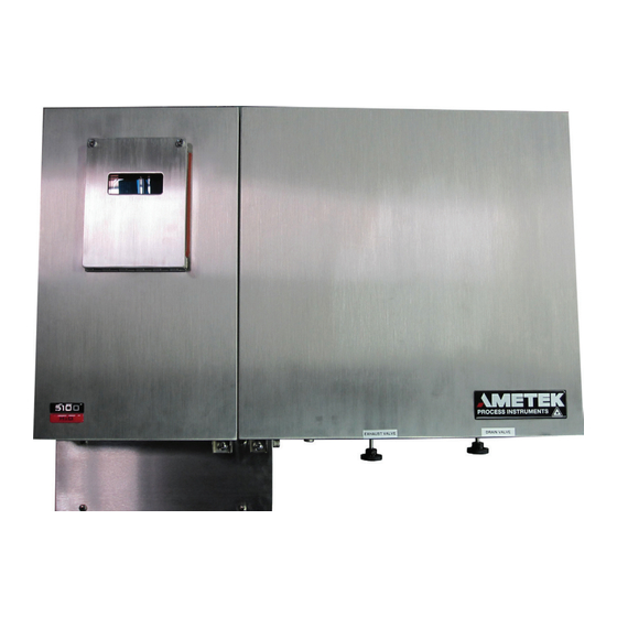
MODEL 5100 HD GAS ANALYZER 5100 HD The AMETEK 5100 HD TDLAS gas analyzer is an extractive system. It is a single-or-dual laser analyzer capable of measuring multiple gas analytes (two laser capability). The unit can also be configured for dual cells. It is comprised of fully enclosed optics, electronics, sample handling and built-in verification. -
Page 14: Tunable Diode Laser Spectroscopy Theory
So, by measuring the intensity of the laser both be- fore and after absorption by the analyte, the number of analyte molecules in the sample can be deter- mined since all of the other terms in the equation are constant. 1-2 | Model 5100 HD Analyzer... -
Page 15: Components
Components The Model 5100 HD consists of three distinct modular components: • Electronics Enclosure/User Interface • Customer Connection Box • Sampling System Electronics Enclosure The electronics enclosure houses the electronics, display, and moisture reference cell and is made of stainless steel and built to withstand harsh environments (IP65). -
Page 16: User Interface
Customer Connection Box The customer connection box is a separate enclosure that houses the terminal strip which provides customer I/O, communication and relay alarm connectivity, the RJ45 Ethernet connector, and the power mains supply. 1-4 | Model 5100 HD Analyzer... - Page 17 Sample Cell Liquid Separator Cell Temperature Sensor Heater The sample inlet port, liquid filter drain and the exhaust port are located on the side for the model 5100 HD. Sample Cell The sample cell consists of : • Sample tube •...
-
Page 18: Detector
The sample flows from the inlet thru a Genie filter where any liquid condensate is removed. The liquid removed flows down the drain vent connection on the side of the 5100 HD. The gas sample then flows thru the sample cell. Cell pressure and temperature are monitored using pressure and temperature sensors respectively. -
Page 19: Laser Line Locking & Built-In Verification
Built-in verification External calibration is time consuming, especially for polar species like water with long equilibration times. Model 5100 HD uses a sealed reference cell (containing moisture vapor in a buffer gas that does not absorb in the spectral range of interest) for quick analyzer verification. The analyzer response is compared to the value of the analyte concentration in the reference cell and the analyzer performance is verified continuously. -
Page 20: Controller Communications
• MQX RTOS and Modbus capability The Model 5100 HD is configured, and analyzer parameters are set, using either the analyzer display and keypad, or the Web Interface. The 4-line x 20-character VFD provides moisture data, system operating parameters, system messages, and alarm conditions. -
Page 21: Options
Options Several options are available • Dual cell capability • High temperature oven • Multiple analytes • High temperature sample cell • Herriott (long path length) sample cell • Space-coupled optics Herriott Sample Cell Option This option is recommended for applications that require enhanced performance at low analyte concentrations. -
Page 22: High Temperature Sample Cell Option
High Temperature Sample Cell Option The 5100 HD oven enclosure is capable of maintaining temperatures up to 150C. Some applications demand a high oven temperature to prevent condensation or plugging. For these situations, a special high temperature cell was designed. The main purpose of this sample cell is to thermally isolate the sensitive components (GRIN lens, detector) from these temperatures. - Page 23 Space-Coupled Option Schematic Overview 1-11...
- Page 24 This page intentionally left blank. 1-12 | Model 5100 HD Analyzer...
-
Page 25: Chapter 2 Specifications
SPECIFICATIONS Please see table on next page. All specifications subject to change without notice. NOTE Specifications... - Page 26 2% of reading, whichever is greater O2 in non-absorbing background: +/- .1% O2 (1.32 mAU) or 2% of reading, whichever is greater H2S in non-absorbing background: +/- .1% (.36 mAU) or 2% of reading, whichever is greater 2-2 | Model 5100 HD Analyzer...
- Page 27 Repeatability H2O in CH4: +/- 4 ppmV (.53 mAU) or +/- 2%, whichever is greater H2O in non-absorbing background: +/- 1 ppmV (.16 mAU) or 2%, whichever is greater CO2 in non-absorbing background: +/- .1% CO2 (10 mAU) or 2% of reading, whichever is greater O2 in non-absorbing background: +/- .1% O2 (1.32 mAU) or 2% of reading, whichever is greater H2S in non-absorbing background: +/- .1 % H2S...
- Page 28 Other ap- provals will include acceptance for use in NEC/CEC Class I Division 2 Groups A, B, C, D T3 and world-wide group II Zone 2 IIC T3 classified hazardous areas. 2-4 | Model 5100 HD Analyzer...
-
Page 29: Chapter 3 Installation And Start-Up
The operations in this chapter should be performed only by qualified service personnel experienced in electrical safety techniques. Never service the analyzer unless power has been removed. This chapter contains information on the installation and setup of the 5100 HD Analyzer including: •... -
Page 30: Analyzer Requirements
Analyzer Requirements Location The Model 5100 HD Analyzer is wall-mounted; ensure that there is adequate clearance when mounting and select a readily accessible position for the analyzer to allow for routine maintenance. The location should be free from excessive vibration and the ambient temperature should be -20 °C to 50 °C (-4 °F to 122 °F) without external... - Page 31 Dimensions 5100 HD (Doors Closed): 26.5” High x 32.7” Wide x 11.9 “ Deep 57.3 cm High x 83.1 cm Wide x 30.2 cm deep Installation & Start-Up...
-
Page 32: Wiring
Keep shields as short as possible. Ground Stud Method Connect all cable shields for the conduit entry hole to the grounding stud closest to the conduit entry hole. 3-4 | Model 5100 HD Analyzer... -
Page 33: Transient And Rfi Interference
Connecting the 5100 HD to Mains Power There is no power switch or circuit breaker in 5100 HD analyzer configured for AC power. The analyzer must be protected by installing it on a circuit-protected line, maximum 15 Amps, with a switch or circuit breaker close to the unit and within easy reach of an operator. - Page 34 Line connection Neutral = Neutral connection (USA) Ground = Ground connections The 5100 HD must be ordered for either 120 VAC or 240 VAC since the oven heater is voltage-specific. 24 VDC Wiring for 5100 HD: GND 24V RET +24 VDC...
-
Page 35: Analyzer Installation
Secondary process seals must be used on all conduit entry points at the customer connection box to prevent gas/liquids from venting to nonclassified locations. Sample Pressure Requirements AMETEK recommends pressure settings between -4.5 and 10 PSIG Minimum input pressure: -4.5 PSIG (-31.3 kPa) (10.2 PSIA) -
Page 36: Gas Connections
Gas Connections Locate the analyzer as close as possible to the sample source and install a main process shut-off valve at the sample tap. All connections to the 5100 HD are made using 1/4”tubing (6mm for metric option) compression fittings. These fittings are located on the right side of the system enclosure. - Page 37 A pre-filter is recommended to prevent liquids and particulates from entering the analyzer. The 5100 HD includes a membrane filter, but this should be considered the last resort protection for the sample cell. An upstream membrane filter should be installed if there is a chance of liquids and/or particulates being present in the sample gas.
-
Page 38: I/O, Communication, And Alarm Relay Connections
Disconnect the power from the analyzer before wiring to the customer connection box. Open the cover on the customer connection box by removing the screws that hold the cover in place. Lift upward and pull away from the box. 3-10 | Model 5100 HD Analyzer... -
Page 39: I/O Signals
I/O Signals Installation & Start-Up 3-11... -
Page 40: Contact Connection
VDC Output -. Connect one side of the switch to the positive (+) terminal of the power supply, and the other side of the switch to Contact Closure + (See following figure). 3-12 | Model 5100 HD Analyzer... -
Page 41: Current Loop Output Connection
Current Loop Output Connection There are two methods that can be used to connect the output current loop to the I/O ports. • Connection using Internal Power Supply Using the internal power supply (VDC Output +), connect the VDC Output terminal to the positive (+) side of the load. -
Page 42: Analog Input - Voltage/Current
For a 5100 HD with two analytes, the above connections are made for loop #2 (second analyte) by using the terminals marked LOOP2 +, LOOP2 -, VDC Output2 +, and VDC Output2 -. The connections are made in the same manner as for Loop #1. -
Page 43: Rs-485 Communication Connection
• Current Input On the analog board find Header J2, place jumpers between Pins 3 and 5, and between Pins 4 and 6. See the following figure. Connect the positive (+) input to the Current Input + terminal, and the negative (-) input to the Current Input –... -
Page 44: 2-Wire Connection
ISOCOM 2-Wire Termination Resistor The 5100 HD is equipped with a termination resistor that can be used for the last unit on the network. Jumper J7 on the MCU board allows you to place a 120- Ohm termination resistor into the RS-485 circuit. See the following figure. -
Page 45: Relay Alarms
Relay Alarms There are four (4) relay alarms available for the 5100 HD. The relays are configured in the software. The settings available for the alarms are: Disable, Concentration, Data Valid, System Alarm, and Normally Open/Normally Closed (NO/NC). Disconnect the power from the analyzer and remove the cover on the customer connection box by removing the screws that hold the cover in place. -
Page 46: Ethernet Cable Connections
Ethernet Cable Connections When using the Ethernet interface on the 5100 HD, the minimum requirement for the Ethernet cable is a CAT 5e (maximum 100 m) cable to connect the analyzer to the network. The maximum distance between the analyzer and the hub is 100 m. -
Page 47: User Interface
User Interface Overview of Keypad The Model 5100 HD keypad is used to access menus, sub-menus and system values, and to set-up analyzer parameters. Press ENTER to access the menus. CALIB Used to define on-demand calibration settings. ALARM Used to define alarm output settings. -
Page 48: Overview Of Display
Sample cell pressure and temperature (or alarm if an alarm exists) There is also a series of blips after the “status” message (Sampling ..) that repeat to indicate the analyzer is functioning. 3-20 | Model 5100 HD Analyzer... -
Page 49: Initial Start-Up
Initial Start-Up Open the main sample shutoff valve at the source. AMETEK recommends you adjust the sample inlet pressure to between -4.5 PSIG and 10 PSIG. Maximum inlet pressure is 10 PSIG. Damage can occur if higher pressures are introduced into the analyzer. - Page 50 This page intentionally left blank. 3-22 | Model 5100 HD Analyzer...
-
Page 51: Chapter 4 User Interface
HD Analyzer and the keypad. Use the arrow keys, BKSP, ENTER, SPACE, num- bers, and period to set the parameters for your analyzer. Figure 4-1a. Keypad and display for the Model 5100 HD Analyzer. Line 1 - - Concentration Line 2 -... -
Page 52: Menu Map
Model 5100 HD Analyzer Menu Map Relay 1 Disable ALARM Analyte Conc High Limit Concentration* Data Valid Low Limit Concentration* System Alarm Test NO/NC Normally Open Normally Closed Relay 2 Disable Analyte Conc High Limit Concentration* Data Valid Low Limit... - Page 53 Auto Cal Ena/Dis Disable TEST/CONFIG Enable Mode Span & Zero Span Only Zero Only Duration (sec)* Internal (hr)* Time (00.00.00)* Auto Adjust Disable Enable Span Value* Zero Value* Modbus Slave Address Address* Baud Rate 9600 19200 Parity None Even Time out (ms) Time* Clock Year...
- Page 54 Background Gas Oxygen Hydrogen Helium Methane Ethane Propane Butane Natural Gas Carbon Dioxide Special Nitrogen Analyte Units Analyte Units (See Moisture Analyte Map Below) SPAN/ZERO Span Span Check CHECK <Target>* Zero Zero Check <Target>* 4-4 | Model 5100 HD Analyzer...
- Page 55 Hold Outputs Disable Enable Moisture Analyte Map H20 Units ppmV ppmW lbs/mmsct mg/nm3 Fixed Pressure Pressure* dew C dew F Transmitter High Pressure Pressure* Low Pressure Pressure* Secondary Unit ppmV ppmW lbs/mmsct mg/nm3 Fixed Pressure Pressure* Transmitter High Pressure Pressure* Low Pressure Pressure* Secondary Unit...
-
Page 56: Alarm
Relay 4 Disable Analyte Conc High Limit Concentration* Data Valid Low Limit Concentration* System Alarm Test NO/NC Normally Open Normally Closed Disable Select this alarm function to disable the alarm for the associated relay. 4-6 | Model 5100 HD Analyzer... -
Page 57: Concentration
Concentration Select this alarm function to set the limits for the concentration. • High Limit Select and then enter the value for the High Limit for the Concentration alarm. • Low Limit Select and then enter the value for the Low Limit for the Concentration alarm. -
Page 58: Analog Range
Enter the reading equivalent to 20 mA. Min Concentration Enter the reading equivalent to 4 mA. Example: To scale the analog output to represent a 0 to 100 PPMV range enter the follow- ing settings: Max Concentration Min Concentration 4-8 | Model 5100 HD Analyzer... -
Page 59: Test Config
Test Config The Test Config key is used to define device and communication settings. See below for information on each section. Modbus Selects the communication setup. The Modbus protocol transmission mode implemented is Remote Terminal Unit (RTU) with the analyzer operating as a slave device. -
Page 60: Clock
Select Hour and enter the numerical value for the hour using the 24-hour clock. Minute Select Minute and enter the numerical value using the 24-hour clock. Select Sec and enter the numerical value for the seconds. 4-10 | Model 5100 HD Analyzer... -
Page 61: Press Disply Units
Press Disply Units Use the Press Disply Units function to select the unit of pressure for the cell to display on the user interface LED when sampling. Select either psia or kPa. psia Press Disply Units Menu for the Pressure Display Unit key. Temp Disply Units Use the Temp Disply Units function to select the unit of temperature for the cell to display on the user interface LED when sampling. -
Page 62: System Test
Menu for the System Test key. Test Relays Tests the relay contacts by toggling them Close / Open. Test Analog Output Tests the analog output by allowing the user to set outputs to 4, 12 or 20 mA. 4-12 | Model 5100 HD Analyzer... -
Page 63: Network
Network The Network Key enables the Model 5100 HD Analyzer to communicate over an Ethernet network to view data, diagnostics, or backing up/restoring the analyzer configuration. Enable NETWORK NETWORK* Disable Enable DHCP* Disable IP ADDRESS* SUBNET* GATEWAY* Menu for the Network key. -
Page 64: Background Gas
Enter High Pressure and a Low Pressure in units of kPa Secondary Unit Choose moisture unit: ppmV, lb/mmscf, or mg/nm If you change the units, remember to make any necessary changes to the Alarm and Analog Range settings. NOTE 4-14 | Model 5100 HD Analyzer... -
Page 65: Zero And Span Check Functions
ZERO and SPAN Check Functions The analyzer may be zeroed and/or spanned as necessary. This is accomplished by using the keypad. When zeroing it is important that the gas applied is known to rep- resent a zero level (of the analyte), in the correct background. For span gas, the concentration of the analyte must be accurately known;... - Page 66 Scroll down to the “Span/Zero Check” menu selection using the down-arrow key: Press ENTER to activate this selection. 4-16 | Model 5100 HD Analyzer...
- Page 67 The following screen will be displayed: To perform a Span Check, scroll to that selection and press ENTER. The follow- ing screen will be displayed (for H2O in this example): User Interface 4-17...
- Page 68 If you do not want to perform the span, press the NO key. To proceed with the span, press the YES key. To change the target value to match the applied analyte concentration, press the enter key. The screen below will appear, prompting you for the new value. 4-18 | Model 5100 HD Analyzer...
- Page 69 The following screen is displayed: The passcode is “123”. It is not necessary to press ENTER after typing the passcode. The software will perform the span automatically once “123” is keyed. If the password is incorrect, the software will display the message “Incorrect Passcode”.
- Page 70 To perform the Zero Check, the steps are the same, beginning with selecting “Zero Check”. The following screen appears: Press “YES” to proceed as for the span. 4-20 | Model 5100 HD Analyzer...
-
Page 71: Modbus Registers
Modbus Registers Data Type Description MB Starting MB Reg Size Regs char[20] Serial Number char[6] MAC address uint IP Address uint IP Subnet Mask uint Gateway uint uint16 DHCP enable. 1=disabled, 2=enabled uint16 TCP Enable. 0=disabled, 1=enabled uint Server IP int16 Version of the params.xml file generated by this... - Page 72 1=0-20 mode. If overange enable (ANAOUT2OR = 1) int16 0 = 3.78 - 20.5, 1 = 0-20.5, high or low val- ues can also be set by fault value, See Fault option (ANAOUT2F) - 4-22 | Model 5100 HD Analyzer...
- Page 73 Data Type Description MB Starting MB Reg Size Regs Current Output 2 Over range Enable. 0=dis- uint16 abled, 1=enabled Current Output 2 Fault Option. 0=No fault, 1=Low fault, 2=High fault. If high fault (2): High end of range becomes 22 mA uint16 Output ratio becomes 1 If low fault (1) AND in 4-20 mode (ANAOUT2T...
- Page 74 Calibration temperature for concentration compensation. float Calibration pressure for concentration com- pensation float Max TEC temperature float Min TEC temperature uint Interval in minutes to save the log data char[10] Concentration Unit of Measure for analyte 2 4-24 | Model 5100 HD Analyzer...
- Page 75 Data Type Description MB Starting MB Reg Size Regs uint Decimal places to use for displaying analyte 1 uint Decimal places to use for displaying analyte 2 boolean Normally closed indicator for relay 1. 1=Nor- mally closed, 0=Normally open boolean Normally closed indicator for relay 2.
- Page 76 Heater 1 Analog Output Scan float Heater 1 Analog Output Offset float Heater 2 Analog Output float Heater 2 Analog Output Scan float Heater 2 Analog Output Offset float Heater 3 Analog Output 4-26 | Model 5100 HD Analyzer...
- Page 77 Data Type Description MB Starting MB Reg Size Regs float Heater 3 Analog Output Span float Heater 3 Analog Output Offset int16 Wavelength Tolerance 1 int16 Wavelength Tolerance 2 float Injection current offset float Temperature Wavelength resolution int16 Median filter size float Minimum Concentration float...
- Page 78 Pressure compensation coefficient 3 float Pressure compensation coefficient 4 int16 Midpoint of the DAC range for TEC control float Concentration of Reference call float Heater Deriviative Time float Heater Duty Cycle float Heater Integral Time 4-28 | Model 5100 HD Analyzer...
- Page 79 Data Type Description MB Starting MB Reg Size Regs float Heater Proportional Band float Cell Sample Time float Heater Deriviative Time float Heater Duty Cycle float Heater Integral Time float Heater Proportional Band float Heater Set Point float Ref Sample Time int16 Midpoint of the DAC range for TEC control float...
- Page 80 Output level 7 float Response value level 7 float Output level 7 float Response value level 7 float Output level 7 float Alpha value for wir filter float Beta value for wir filter 4-30 | Model 5100 HD Analyzer...
- Page 81 Data Type Description MB Starting MB Reg Size Regs float Power correction alpha int16 Beta value for wir filter float Power correction Z value float Duty cycle for the sample heater float Power correction Z value 2 float Laser power of sample channel float Laser power reference of sample channel float...
- Page 82 Cross-over point for Alyte 3 concentration int16 Switching analyte int16 Time until next cal cycle char[20] The auto calibration schedule. -1 is disabled. The time should be a number like 14:30:45 for 2:30:45 PM. char[20] Next schedule for calibration 4-32 | Model 5100 HD Analyzer...
- Page 83 Modbus Registers Modbus Description Alarm Type Register SYSALARM_TECTEMP_HI Alarm SYSALARM_TECTEMP_LO Alarm SYSALARM_TECTEMP2_HI Alarm SYSALARM_TECTEMP2_LO Alarm SYSALARM_CELLTEMP_HI Alarm SYSALARM_CELLTEMP_LO Alarm SYSALARM_PRESST_HI Alarm SYSALARM_PRESST_LO Alarm SYSALARM_SEALPRES_HI Alarm SYSALARM_SEALPRES_LO Alarm SYSALARM_INTERNAL_SW_ERROR Alarm SYSALARM_INTERNAL_HW_ERROR Alarm SYSALARM_TEC_DRIFT_ERROR Warning SYSALARM_TEC2_DRIFT_ERROR Warning SYSALARM_CONC_RANGE1 Warning SYSALARM_CONC_RANGE2 Warning SYSALARM_LASER_POWER2 Warning SYSALARM_BATTERY_FAIL Warning...
-
Page 84: Alarm Messages
• Low moisture in reference cell Low light intensity “Low light intensity” Reference concentration “Ref conc. alarm” Calculated reference concentration is out of tolerance Internal error “Internal error” • File system error • Memory error • I/O communication error 4-34 | Model 5100 HD Analyzer... -
Page 85: Chapter 5 Web Interface
3. Route the cable to the network connection in the plant and connect it. To connect to the 5100 HD Analyzer web interface, you need to know the IP Address used by your network. The IP Address can be found by using the analyzer display to navigate to TEST CONFIG, then Network, then IP Address. -
Page 86: Web Interface Connection
Open any browser (Internet Explorer, Netscape, etc.) and type the IP Address into the address box and click Return. Example: http://10.52.236.54 The 5100 HD web interface Home page opens (See below). The Home page displays a graphic of the analyzer indicating current parameters and location of the following: •... -
Page 87: Web Interface Screen
Web Interface Screen The web interface screen is divided into four distinct areas: 1. Status Bar Displays the state of the analyzer including: Status (Line Lock or Sampling) Line Lock - system is determining peak position for signal at reference cell Sampling - System is collecting data through sample cell Analyte Concentration Sample Cell Pressure... -
Page 88: Conditions And Messages
Conditions and Messages The 5100 HD Web Interface is shipped from the factory without password protection, allowing all configurable parameters to be changed. Trend and spectral data are stored in temporary memory. For security reasons, temporary data cannot be stored directly on a computer or network. -
Page 89: Alarm Menu
Alarm Menu Click the Alarms button to access the Alarms and the Alarms:History sub- menus. Alarms The Alarms window displays any active analyzer alarm condition as determined by the built-in Diagnostics. A maximum of 15 active alarms and warnings can be displayed. -
Page 90: Alarms: History
The activity that caused the alarm, warnings, system and other events can be displayed using the check boxes for the Alarm Filter Messages. This screen is Read-only. 5-6 | Model 5100 HD Analyzer... -
Page 91: Trends Menu
Trends Menu Click the Trends button to access parameters (Figure 5-5) for: • Sample Cell Temperature • Sample Cell Pressure • Analyte Concentration • Reference Temperature • Laser Temperature Trend intervals for parameters are available in 30-second, 3005-seconds or 1800-second data points. The analyzer stores 3600 parameter data points in temporary ... - Page 92 Click on the down arrow to the right of the Select Parameter window to view a different trend: Click on the down arrow to the right of the interval window to change the time interval for the current trend: 5-8 | Model 5100 HD Analyzer...
-
Page 93: Spectra Menu
Spectra Menu Click the Spectra button to view live spectrum and Reference spectrum side by side in the display window. Web Interface... -
Page 94: Settings Menu
Settings: Relays Using the Relay display window, you can set up parameters for up to four relays. Each relay supports alarms for the following: • Concentration Limits High and Low limits 5-10 | Model 5100 HD Analyzer... -
Page 95: Settings: Current Outputs
• Data Valid Indicates the instrument data is valid. • System Alarm Triggers to indicate a system alarm condition. Changes are not saved to the instrument until the “Save” button is pressed. NOTE Settings: Current Outputs Use the Current Output display window to set the parameters for a single current output. - Page 96 • Over Range Check Box Allows current output to slightly exceed limits rather than clamping output. Changes are not saved to the instrument until the “save” button is pressed. NOTE 5-12 | Model 5100 HD Analyzer...
-
Page 97: Settings: Configuration
Settings: Configuration Use the Configuration display window to identify system and communication settings. Ethernet • DHCP (Dynamic Host Configuration Protocol ) Enabled IP address is obtained from a DHCP server on the network. If no DHCP server is found, it defaults to 169.254.1.1 •... -
Page 98: System
Use the drop-down list box to select stop bits. • Modbus Address Enter the Modbus address for the instrument. • Modbus Timeout Enter the number of milliseconds (msec) before Modbus communication will time out. 5-14 | Model 5100 HD Analyzer... -
Page 99: Customization
Customization • Date Format Use the drop-down list box to select the date format. • Decimal Point Use the drop-down list box to select either decimal point or period. Changes are not saved to the instrument until the “Save + reset” ... - Page 100 This page intentionally left blank. 5-16 | Model 5100 HD Analyzer...
-
Page 101: Chapter 6 Maintenance
SUBSTITUTION OF RLY1 MAY IMPAIR SUITABILITY FOR USE IN HAZARDOUS AREAS. replace only with the same type - AMETEK part number 25869JE. EXPLOSION HAZARD! Do not remove or replace components un- less power has been disconnected or the area is known to be free of ignitable concentrations of flammable gases or vapors. -
Page 102: Cleaning
The battery on the MCU board powers the analyzer clock when the main analyz- er AC power is not connected. The clock’s primary function is to timestamp the Alarm Log entries. The AMETEK part number for one battery is #301-0382. The battery’s expected life-span is greater than five years; therefore, it is impor- tant to order and stock a battery when your analyzer is approaching five years from the original manufacture date. - Page 103 Hazardous Location Applications: If an external, flame-proof disconnect switch (breaker) has been installed, close the breaker. If no external breaker has been installed, follow the power up procedure for “General Purpose (GP) Applications” below. Before proceeding, test the area around the analyzer for flammable gases. If an explosive gas atmosphere is present, do not power down the analyzer or any alternate power sources that supply power to the analyzer components.
-
Page 104: Containment System Leaks
For ¼” and 6 mm fittings, wrench-tighten 1-1/4 turns past finger-tight. • When reassembling a sample cell, ensure than all screws are tightened suffi- ciently to bring the cell pieces into contact (bottom out). 6-4 | Model 5100 HD Analyzer... -
Page 105: Parameter Id & Modbus Registers
Parameter ID & Modbus Registers Parameter ID & Modbus Registers All system parameters can be identified by a parameter ID. Telnet/Terminal interface use this ID to All system parameters can be identified by a parameter ID. Telnet/Terminal inter- view, set, and trend the parameter’s value face use this ID to view, set, and trend the parameter’s value Access: r: read, w: write, s: system, f: factory, h: hidden Access: r: read, w: write, s: system, f: factory, h: hidden... - Page 106 (ANAOUT2T = 0): Low end of range becomes 3 mA Output ratio becomes 0. uint16 RELAY1 Relay 1. 0=OPEN, 1=CLOSED uint16 RELAY1D Relay 1 Delay. Holds the relay output for this set amount of time. uint16 RELAY1F Relay 1 Function. 0=Disabled, 1=Concentration, 3=Data Valid, 6-6 | Model 5100 HD Analyzer 4=System alarm uint16 RELAY1S Relay 1 Source. The source parameter number used to evaluated the relay function.
- Page 107 (ANAOUT2T = 0): Low end of range becomes 3 mA Output ratio becomes 0. uint16 RELAY1 Relay 1. 0=OPEN, 1=CLOSED uint16 RELAY1D Relay 1 Delay. Holds the relay output for this set amount of time. uint16 RELAY1F Relay 1 Function. 0=Disabled, 1=Concentration, 3=Data Valid, 4=System alarm uint16 RELAY1S Relay 1 Source. The source parameter number used to evaluated the relay function. float RELAY1V Relay 1 Value. The value used to evaluate the relay function. uint16 RELAY2 Relay 2. 0=OPEN, 1=CLOSED...
- Page 108 STCELLP Static cell pressure. Use by setting STATICPT to 1 or 3 int16 ANAOUT1H Analog output 1, 0 - follow source 6-8 | Model 5100 HD Analyzer during cal, 1 - hold output during cal int16 ANAOUT2H Analog output 2, 0 - follow source during cal, 1 - hold output during cal...
- Page 109 (STCELLT) static value usage. 0=neither, 1=use static pressure, 2=use static temperature, 3= use both float STCELLT Static cell temperature. Use by setting STATICPT to 2 or 3 float STCELLP Static cell pressure. Use by setting STATICPT to 1 or 3 int16 ANAOUT1H Analog output 1, 0 - follow source during cal, 1 - hold output during cal int16 ANAOUT2H Analog output 2, 0 - follow source...
- Page 110 Trending parameter int16 TRENDPAR16 Trending parameter int16 TRENDPAR17 Trending parameter int16 TRENDPAR18 Trending parameter int16 TRENDPAR19 Trending parameter 6-10 | Model 5100 HD Analyzer int16 TRENDPAR20 Trending parameter int16 TRENDPAR21 Trending parameter int16 TRENDPAR22 Trending parameter int16 TRENDPAR23 Trending parameter...
- Page 111 int16 TRENDPAR11 Trending parameter int16 TRENDPAR12 Trending parameter int16 TRENDPAR13 Trending parameter int16 TRENDPAR14 Trending parameter int16 TRENDPAR15 Trending parameter int16 TRENDPAR16 Trending parameter int16 TRENDPAR17 Trending parameter int16 TRENDPAR18 Trending parameter int16 TRENDPAR19 Trending parameter int16 TRENDPAR20 Trending parameter int16 TRENDPAR21 Trending parameter...
- Page 112 RLEVEL10_2 Response value level 7 float OLEVEL10_2 Output level 7 float ALPHA2 Alpha value for wir filter float BETA2 Beta value for wir filter 6-12 | Model 5100 HD Analyzer float PWRALPHA_2 Power correction alpha int16 AVESIZE_2 Beta value for wir filter float ZVALUE_2 Power correction Z value...
- Page 113 float OLEVEL7_2 Output level 7 float RLEVEL8_2 Response value level 7 float OLEVEL8_2 Output level 7 float RLEVEL9_2 Response value level 7 float OLEVEL9_2 Output level 7 float RLEVEL10_2 Response value level 7 float OLEVEL10_2 Output level 7 float ALPHA2 Alpha value for wir filter float BETA2 Beta value for wir filter float PWRALPHA_2 Power correction alpha int16 AVESIZE_2 Beta value for wir filter float ZVALUE_2 Power correction Z value...
- Page 114 Background 2 gas span factor float BGRNDMOLW2 Background 2 gas mol weight char[20] BGRNDGAS2 Background gas name float BGNDFACTOR2 background factor float BGNDNORMTEMP2 background normal temperature float REFCONCOMP2 background normal temperature int16 CALIBALYTE status of zero check 6-14 | Model 5100 HD Analyzer...
-
Page 115: System Alarm/Warning Bit Map
System Alarm/Warning bit map System Alarm/Warning bit map When System Status (parameter 129, 16-bit integer, modbus register 117) con- When System Status (parameter 129, 16-bit integer, modbus register 117) contains none-zero value, tains none-zero value, the bit map of System Alarms and System Warning (pa- the bit map of System Alarms and System Warning (parameter 125, 126, 127, 128;... - Page 116 0 = 3.78 - 20.5, 1 = 0-20.5, high or low values can also be set by fault value, See Fault option (ANAOUT1F) uint16 ANAOUT1OR Current Output 1 Over range Enable. 0=disabled, 1=enabled uint16 ANAOUT1F Current Output 1 Fault Option. 0=No fault, 1=Low fault, 2=High fault. If high fault (2): High end of range becomes 22 mA 6-16 | Model 5100 HD Analyzer Output ratio becomes 1 If low fault (1) AND in 4-20 mode (ANAOUT1T = 0): Low end of range becomes 3 mA...
- Page 117 0 = 3.78 - 20.5, 1 = 0-20.5, high or low values can also be set by fault value, See Fault option (ANAOUT1F) uint16 ANAOUT1OR Current Output 1 Over range Enable. 0=disabled, 1=enabled uint16 ANAOUT1F Current Output 1 Fault Option. 0=No fault, 1=Low fault, 2=High fault. If high fault (2): High end of range becomes 22 mA Output ratio becomes 1 If low fault (1) AND in 4-20 mode (ANAOUT1T = 0): Low end of range becomes 3 mA Output ratio becomes 0. float ANAOUT2 Current Output 2 - float...
- Page 118 2nd Concentration Unit of Measure for analyte 1 uint DATAVALID_2 Data Valid. 0=Not Valid, 1=Valid int16 DMODE_2 0=Line-lock mode, 1=Sample, 2=Calib float SEALPRESMAX Process seal max 6-18 | Model 5100 HD Analyzer float SEALPRESMIN Process seal min float TECTEMP_2 TEC Temperature Value float TEMPREF_2 Reference temperature for this diode...
- Page 119 float CELLPRES PRESX1 Analog Input Filtered value float CONCMIN Minimum Concentration float CONCMAX Maximum Concentration float REFCONC Concentration of Reference call float ALYTE1CONS Analyte 1 Concentration in other unit char[20] CONCUNITS 2nd Concentration Unit of Measure for analyte 1 uint DATAVALID_2 Data Valid. 0=Not Valid, 1=Valid int16 DMODE_2 0=Line-lock mode, 1=Sample, 2=Calib float SEALPRESMAX Process seal max...
- Page 120 6-20 | Model 5100 HD Analyzer...
-
Page 121: Appendix A Auto Cal Feature
AUTO CAL FEATURE AMETEK is pleased to introduce a new Auto Cal feature to the 5100HD. This feature allows for the timer-actuated (automatic) validation or calibration adjustment of the analyzer using span and/or zero gas standards. A manually- actuated span/zero feature has been present in the 5100HD for some time, and a detailed description of this feature may be found in chapter 4 (User Interface) of this manual. - Page 122 Instructions for setting the clock may be found in Chapter 4. NOTE Alarms: History From the main operating screen, press the Enter key. Scroll to the “Test/Config” selection and press Enter. A-2 | Model 5100 HD Analyzer...
- Page 123 Scroll to the “Auto Cal” selection and press Enter. The first menu option listed is “Ena/Dis”. Selecting this option allows the user to enable or disable the Auto Cal feature. Any Auto Cal schedule set up previously will not occur if “Disable” is selected. Appendix A | A-3...
- Page 124 The second menu option is “Mode”. This allows the user to select between “Span & Zero”, “Zero only”, and “Span only”. A-4 | Model 5100 HD Analyzer...
- Page 125 The third menu option is “Duration (sec)”. As the name implies, the amount of time the gas will be read by the analyzer before performing the calcu- lations must be entered, in seconds. A typical value for this is 120 seconds (two minutes).
- Page 126 Backspace to exit. Next is “Time (00.00.00)”, which is the time of day for the first Auto cal to occur. Enter the time in military format. For example, 3 pm would be 15:00:00 A-6 | Model 5100 HD Analyzer...
- Page 127 Next is “Span value”, which is the concentration of the applied span gas. Change the value if necessary. Next is “Zero value”, the concentration of the applied zero gas (typically Appendix A | A-7...
- Page 128 Change if necessary. The last selection is “Auto Adjust”, which establishes whether or not a A-8 | Model 5100 HD Analyzer...
- Page 129 check (or bump) is performed (disable), or a span/zero adjustment is performed (enable). Appendix A | A-9...
- Page 130 “CONTACT CLOSURE” in the wiring enclosure (under the main elec- tronics cabinet). Upon detecting the switch closure, the analyzer will display an alarm message, which may also be mapped to an alarm relay. A-10 | Model 5100 HD Analyzer...
- Page 131 The following two pages show a general arrangement drawing for this configura- tion of the 5100 HD. A heated sample line entry boot is used for both the process gas inlet and return to process lines. Unlike other 5100 HD versions, there is no membrane separator/filter included in the analyzer oven.
- Page 132 B-2 | Model 5100 HD Analyzer...
- Page 133 Appendix B | B-3...
- Page 134 ASSY REFERENCE CELL 5100 HD P/N 76638SE SAMPLE CELL RTD P/N 76647SE RAIL, DIN, 35MM X 7.5MM PERORATED, 75MM LONF, 5100 HD P/N 76779KE ASSY, CABLE, 180W TRACO POWER SUPPLY, 5100 HD P/N 76793SE ASSY, CABLE, POWER SUPPLY TO D-D CONVERTER, 5100 HD...
Need help?
Do you have a question about the 5100 HD and is the answer not in the manual?
Questions and answers