Table of Contents
Advertisement
Quick Links
Advertisement
Table of Contents

Related Manuals for Ametek CHANDLER ENGINEERING 5265


Summary of Contents for Ametek CHANDLER ENGINEERING 5265
- Page 1 Instruction Manual Model 5265 Static Gel Strength Analyzer Original Instructions Revision AB – January 2016 P/N: 83-0005 S/N: ____________ “ ” : 614007, . . 25 : +7 (342) 262-85-56 : +7 (342) 262-85-60 email: office@techimp[ort.ru www.techimport.ru...
- Page 2 This publication contains the following trademarks and/or registered trademarks: AMETEK, CHANDLER ENGINEERING. These trademarks or registered trademarks and stylized logos are all owned by AMETEK, Inc. All other company, product and service names and logos are trademarks or service marks of their respective owners.
-
Page 3: Table Of Contents
TABLE OF CONTENTS Table of Contents General Information ..............P-1 Introduction..........................P-1 Description ........................P-1 Features and Benefits ......................P-1 Specifications ......................... P-2 Safety Requirements ......................P-3 Symbols Used on Equipment....................P-4 Symbols Used in this Manual ....................P-5 Section 1 – Installation ............. 1-1 Unpacking the Instrument ..................... - Page 4 TABLE OF CONTENTS Running a Test ........................2-7 Pressure Control ......................2-7 Temperature Control ....................2-8 Ending a Test ........................2-8 Cleaning the Test Cell ....................... 2-9 Section 3 – Maintenance ............3-1 Maintenance ........................3-1 Tools Required ........................3-1 Cleaning and Service Tips ....................
-
Page 5: General Information
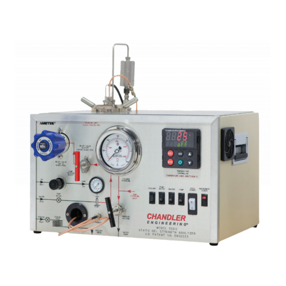
PREFACE General Information Introduction This manual contains installation, operation, and maintenance instructions for the Chandler Engineering Model 5265 Static Gel Strength Cement Analyzer. Description The 5265 Static Gel Strength Cement Analyzer (SGSA) is an instrument that measures the static gel strength of API cement under high temperature and high- pressure conditions. -
Page 6: Specifications
PREFACE Specifications 5265 400°F (204°C) Maximum Curing Temperature: 20,000 psi (138 MPa) Maximum Curing 2,000 Watts Pressure: Heater Power: Electrical Main Input Voltage: 208-240 VAC, 50/60 Hz, 10A Instrument Input Voltage: 115/230 VAC, 50/60Hz, 2.5A (Includes QTY 2, 2.5 A, 250VAC, 5x20mm, Time Lag Fuses) Shipping Dimensions and Weight Dimensions... -
Page 7: Safety Requirements
PREFACE Safety Requirements READ BEFORE ATTEMPTING OPERATION OF INSTRUMENT If this equipment is not used in a manner consistent with the manufacturer’s specifications the protection provided by the equipment may be impaired. Warning: Read before attempting operation of this instrument. This instrument is capable of high temperatures and pressures and must always be operated with CAUTION. -
Page 8: Symbols Used On Equipment
PREFACE • A fire extinguisher, type 8 BC, should be located within 50 feet (15 meters) of the instrument. Before attempting to operate the instrument, the operator should read and understand this manual. Symbols Used on Equipment Symbol Meaning Protective Conductor Terminal Caution, risk of electric shock. -
Page 9: Symbols Used In This Manual
PREFACE Symbols Used in this Manual Symbol Meaning Note, Important Information Warning, Potential Hazard... - Page 10 PREFACE This page is intentionally left blank.
-
Page 11: Section 1 - Installation
SECTION 1 – INSTALLATION Section 1 – Installation Unpacking the Instrument Re-configuration 1. Apply power to the instrument. 2. Make sure the instrument is connected to serial port COM1 on the host computer. 3. Turn ON the power to the instrument. 4. -
Page 12: Connecting Serial Power
SECTION 1 – INSTALLATION Connecting Serial Power Use the configuration software (SIXBCCD.EXE) to configure the individual data channel addresses. A basic schematic for connecting one autoclave to another is shown in the following figure. One autoclave in each 5265 SGSA system must be connected to serial port COM1 on the host computer using a standard 25 pin male to 25 pin female or 25 pin male to 9 pin female RS-232 serial cable, depending on the computer. -
Page 13: Section 2 - Operating Instructions
SECTION 2 – OPERATING INSTRUCTIONS Section 2 – Operating Instructions Front Panel Controls The figure below shows the front panel and all the associated controls. The description of each control will follow the figure. Air Inlet Gauge This gauge displays the pressure of the air supply connected to the autoclave. The pressure should be between 50 and 100 psig (340 and 690 kPa) when the pump is not in use. -
Page 14: Verification Of Signal Strength
SECTION 2 – OPERATING INSTRUCTIONS Verification of Signal Strength You can verify the proper signal strength by running the following test: 1. Set up instrument to run a water test. • Starting temperature: Room temperature • Initial Pressure: 1,000 psig 2. -
Page 15: Pressure Release Valve
SECTION 2 – OPERATING INSTRUCTIONS coolant switch in the OFF position to avoid possible temperature oscillations at temperatures above room temperature. Pressure Release Valve Used to manually release pressure from the test cell. Valve must be closed during testing except when it is necessary to manually release pressure. Valve must also be closed when removing test cell with cooling water ON or else a significant water leak will occur. -
Page 16: Monitor Cable Connector
SECTION 2 – OPERATING INSTRUCTIONS Monitor Cable Connector This connector is used for monitoring the ultrasonic signals within the test cell. Normally it is not used. It may be used during system testing. Top Transducer Connector The coaxial cable attached to the top transducer must be mated to this connector prior to beginning a test. -
Page 17: Operating The Instrument
SECTION 2 – OPERATING INSTRUCTIONS Operating the Instrument 1. Install the Model 5270 Data Acquisition Software in accordance with the instructions found in the software manual. 2. Connect power to the instrument using the cord and twist-lock connector supplied with the autoclave. -
Page 18: Preparing The Sample And Cell For A Test
SECTION 2 – OPERATING INSTRUCTIONS Preparing the Sample and Cell for a Test The recommended procedure for preparing the test cell and slurry for testing are outlined in the following steps: 1. Always check the sealing components to make sure they are clean and in good condition. If the O-rings are deformed or hardened replace them. -
Page 19: Running A Test
SECTION 2 – OPERATING INSTRUCTIONS 8. Continue to pour cement in test cell until level is 1/4 inch (6mm) below the circular lip in the cylinder. Use the Slurry Level Gauge to obtain the proper fill level. The slurry should touch the lower tab marked WET but not touch the upper tab marked DRY. Do not overfill the test cell, or cement will be forced into the pressure and/or thermocouple ports, and plug them. -
Page 20: Temperature Control
SECTION 2 – OPERATING INSTRUCTIONS 1. Make certain the test cell is installed properly, the HIGH PRESSURE INLET port on the rear of the instrument is plugged, the PUMP switch is in the OFF position, the PUMP WATER valve is turned to the ON position, and the instrument is supplied with compressed air. 2. -
Page 21: Cleaning The Test Cell
SECTION 2 – OPERATING INSTRUCTIONS pressure at temperatures above 212 ° F (100 ° C) may cause water in the test cell to become steam. 2. Turn the PUMP WATER switch to the OFF position. 3. Turn MAIN POWER and INSTRUMENT POWER switches OFF. 4. - Page 22 2-10 SECTION 2 – OPERATING INSTRUCTIONS This page is intentionally left blank.
-
Page 23: Section 3 - Maintenance
SECTION 3 – MAINTENANCE Section 3 – Maintenance This section describes the basic maintenance that is required for the 5265 Autoclaves. A troubleshooting guide is also provided in the event that a problem occurs. Maintenance The 5265 Autoclave requires very little routine maintenance. Following the recommendations listed below will allow years of trouble free operation. -
Page 24: Regulator Rebuild Instructions
SECTION 3 – MAINTENANCE 1. Remove the cell from the instrument. 2. Thoroughly clean the cell in preparation for calibration. 3. Unscrew the bottom plug until the threads are approximately 1/2 engaged. 4. Insert the foam-centering sleeve for the calibration bar. 5. -
Page 25: Bonnet Disassembly/Reassembly
SECTION 3 – MAINTENANCE 8. Unscrew the seat retainer (Item 004) from the body Item (001) and remove the seat (Item 003). 9. Clean the seat retainer. 10. Replace the seat (Item 003). Place the beveled (chamfered) side of the seat facing out toward the sensor assembly stem. -
Page 26: Major Assembly
SECTION 3 – MAINTENANCE Major Assembly 1. Place the sensor assembly back into the body (Item 001). Place a small amount of O-ring lubricant on the O-ring (Item 0052). Push the assembly into place using the needle nose pliers. 2. Screw the bonnet assembly with the spring into the body. Place a small amount of anti-seize lubricant on the threads. -
Page 27: Section 4 - Troubleshooting Guide
SECTION 4 – TROUBLESHOOTING GUIDE Section 4 – Troubleshooting Guide The following table lists symptoms of several common problems, the possible cause of the problem, and the possible solution to the problem. Symptom Possible Cause Possible Solution Disconnect power to instrument and Short circuit in system check for short circuits with an wiring. - Page 28 SECTION 4 – TROUBLESHOOTING GUIDE Symptom Possible Cause Possible Solution Pump operates, but CYLINDER WATER will not build valve is not open or Open CYLINDER WATER valve pressure. water is not being and check flow of water to the supplied to the instrument.
- Page 29 SECTION 4 – TROUBLESHOOTING GUIDE Symptom Possible Cause Possible Solution Increase proportional band using Temperature Temperature controller overshoots the soak PROPORTIONAL temperature controller tune loop. value. BAND tuning parameter too low. Temperature controller Decrease the integral time using Ti tuning parameter too the temperature controller tune high.
- Page 30 SECTION 4 – TROUBLESHOOTING GUIDE This page is intentionally left blank.
-
Page 31: Section 5 - Replacement Parts
SECTION 6 – REPLACEMENT PARTS Section 6 - Replacement Parts Part Number Description 80-0016 Sealing Ring 80-0021 Thermocouple, Type J, 20000 psig 80-0022 Heating/Cooling Jacket, 2000 W, 50/60 Hz 80-0024 Heating Jacket End Gasket 80-0025 Heating Jacket Bottom Gasket 80-0026 Heating Jacket Centering Ring 80-0031 Anti-Rotation Bracket... - Page 32 SECTION 6 – REPLACEMENT PARTS To ensure correct part replacement, always specify Model and Serial Number of instrument when ordering or corresponding. 5265-REPL_PARTS REV C...
-
Page 33: Section 6 - Drawings And Schematics
SECTION 6 – DRAWINGS AND SCHEMATICS Section 6 - Drawings and Schematics Drawing Number Description Scan Software Setup Instructions 83-0006 Plumbing Diagram 83-0007 Wiring Diagram 83-0044 Rear Panel Layout 83-0046 Front Panel Layout 84-0057 High Temp Cable Assembly 5265-0100 Vessel Assy w/Cables 5265-DWGS REV C... - Page 34 SECTION 6 – DRAWINGS AND SCHEMATICS This page is intentionally left blank. 5265-DWGS REV C...
- Page 35 SCAN SOFTWARE Scan Software Setup Instructions A copy of Scan software is included with every 5270 DACS CD. The following are intended to help find and install the Scan software. 1. Insert the 5270 DACS CD into the CD player. 2.
- Page 36 ...
- Page 38 CHANDLER ENGINEERING...
- Page 40 CHANDLER ENGINEERING...
- Page 42 DESCRIPTION DATE APPROVED ISSUED 1/21/16 80-0050 80-0016 C08565 CABLE ASSY C08584 SEAL RING ORING TRANSDUCER ULTRASONIC C08565 80-0016 (PAIR) C08584 ORING SEAL RING TRANSDUCER, 80-0010 C08564 ULTRASONIC C08606 TOP PLUG RETAINING RING 80-0010 (PAIR) BNC ADAPTER BOTTOM 80-0010 PLUG 80-0050 VESSEL CABLE ASSY 80-0057...
Need help?
Do you have a question about the CHANDLER ENGINEERING 5265 and is the answer not in the manual?
Questions and answers