HPE ProLiant DL325 Gen10 Plus v2 User Manual
Hide thumbs
Also See for ProLiant DL325 Gen10 Plus v2:
- Maintenance and service manual (174 pages) ,
- User manual (149 pages)

Related Manuals for HPE ProLiant DL325 Gen10 Plus v2


Summary of Contents for HPE ProLiant DL325 Gen10 Plus v2
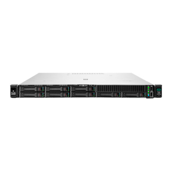
- Page 1 HPE ProLiant DL325 Gen10 Plus v2 Server User Guide HPE ProLiant DL325 Gen10 Plus v2 Server User Guide Part Number: 30-25EA2ED1-003 Published: March 2022 Edition: 3...
- Page 2 HPE ProLiant DL325 Gen10 Plus v2 Server User Guide HPE ProLiant DL325 Gen10 Plus v2 Server User Guide Abstract Abstract This document is for the person who installs, administers, and troubleshoots servers and storage systems. Hewlett Packard Enterprise assumes you are qualified in the servicing of computer equipment and trained in recognizing hazards in products with hazardous energy levels, and are familiar with the weight and stability precautions for rack installations.
-
Page 3: Table Of Contents
1.8 PCIe4 slot description 1.9 Riser board components 1.10 DSC-25 2-port SFP28 card ports and LEDs 1.11 HPE NS204i-p NVMe OS Boot Device components 1.12 HPE NS204i-p NVMe OS Boot Device LED definitions 1.13 Fan numbering 2 Operations 2.1 Remove the front bezel 2.2 Power up the server... - Page 4 4.10.2 Fan mode behavior 4.10.3 Installing the high-performance fans 4.11 Memory options 4.11.1 DIMM population information 4.11.2 HPE SmartMemory speed information 4.11.3 Installing a DIMM 4.12 Secondary riser cage options 4.12.1 Installing the secondary riser option for half-height expansion cards...
- Page 5 4.16 M.2 SSD options 4.16.1 Installing the M.2 SATA SSD enablement option 4.16.2 HPE NS204i-p NVMe OS Boot Device option 4.16.2.1 Installing the HPE NS204i-p NVMe OS Boot Device option 4.17 OCP NIC 3.0 adapter option 4.17.1 Installing an OCP NIC 3.0 adapter 4.18 Chassis intrusion detection switch option...
- Page 6 10.2 Mechanical specifications 10.3 Power supply specifications 10.3.1 HPE 500 W Flex Slot Platinum Hot-plug Low Halogen Power Supply (94% efficiency) 10.3.2 HPE 800 W Flex Slot Platinum Hot-plug Low Halogen Power Supply 10.3.3 HPE 800 W Flex Slot Titanium Hot-plug Low Halogen Power Supply 10.3.4 HPE 800 W Flex Slot Universal Hot-plug Low Halogen Power Supply...
-
Page 7: Component Identification
Component identification Component identification This chapter describes the external and internal server features and components. Component identification... -
Page 8: Front Panel Components
Front panel components Front panel components LFF front panel components LFF front panel components Item Item Description Description Optical drive (optional) Serial number/iLO information pull tab iLO service port USB 3.0 port LFF drive bays The serial number/iLO information pull tab is double-sided. One side shows the server serial number and the customer asset tag label. - Page 9 label. The other side shows the default iLO account information. The server supports two 2 SFF drive cage options. The following drive types are supported: SATA, SAS, U.2 NVMe, and U.3 NVMe drives. The universal media bay supports the optical drive or the 2 SFF drive cage option. The 8 SFF drive cage supports the following drive types: SATA, SAS, U.2 NVMe, and U.3 NVMe drives.
- Page 10 You cannot access the server by connecting to the Service Port. You cannot access the connected device from the server. For more information about the iLO Service Port, see the iLO user guide at the following website: https://www.hpe.com/support/ilo- https://www.hpe.com/support/ilo- docs.
-
Page 11: Front Panel Leds And Buttons
Front panel LEDs and buttons Front panel LEDs and buttons LFF front panel LEDs and buttons LFF front panel LEDs and buttons SFF front panel LEDs and button SFF front panel LEDs and button Item Item Description Description Status Status Definition Definition UID button/LED... - Page 12 When all LEDs flash simultaneously, a power fault has occurred. For more information, see Front panel LED power fault codes. If the health LED indicates a degraded or critical state, review the system Integrated Management Log (IML) or use HPE iLO to review the system health status.
-
Page 13: Server Uid Led
Server UID LED Server UID LED The UID LED is used to locate a particular server when it is deployed in a dense rack with other equipment. Activating the UID LED helps an on-site technician to quickly identify a server for maintenance tasks. Server UID LED... -
Page 14: Using The Uid Button To View The Server Health Summary
1. Press and release the UID button. The Server Health Summary screen is displayed on the external monitor. For more information, see the iLO troubleshooting guide on the Hewlett Packard Enterprise website ( https://www.hpe.com/support/ilo-docs https://www.hpe.com/support/ilo-docs). 2. Press the UID button again to close the Server Health Summary screen. -
Page 15: Front Panel Led Power Fault Codes
Front panel LED power fault codes Front panel LED power fault codes The following table provides a list of power fault codes, and the subsystems that are affected. Not all power faults are used by all servers. Subsystem Subsystem LED behavior LED behavior System board 1 flash... -
Page 16: Rear Panel Components
Rear panel components Rear panel components Item Item Description Description Slot 1 PCIe4 x16 (16, 8, 4, 1) Slot 2 PCIe4 x16 (16, 8, 4, 1) Slot 3 PCIe4 x16 (16, 8, 4, 1) (optional) Flex Slot power supply 2 (optional) Flex Slot power supply 1 Serial port (optional) USB 3.0 ports (2) -
Page 17: Rear Panel Leds
Rear panel LEDs Rear panel LEDs Item Item Status Status Definition Definition iLO link Solid green Network link No network link iLO status Solid green Linked to network Flashing green Network active No network activity Solid blue Activated Flashing blue 1 flash per sec = Remote management or firmware upgrade in progress 4 flashes per sec = iLO manual reboot sequence initiated... -
Page 18: System Board Components
System board components System board components Item Item Description Description Serial port connector Secondary PCIe4 riser connector System maintenance switch Storage controller backup power connector 2 Graphics card power connector 2 Primary PCIe4 riser connector System battery NVMe port 6A OCP NIC 3.0 slot OCP NIC 3.0 x16 upgrade connector Internal USB 3.0 port... - Page 19 Item Item Description Description NVMe port 5A Front I/O connector Fan connector 8 Graphics card power connector 1 Fan connector 7 Fan connector 6 TPM connector Fan connector 5 Fan connector 4 NVMe port 3A NVMe port 1A Fan connector 3 NVMe port 2A Fan connector 2 Fan connector 1...
-
Page 20: System Maintenance Switch Descriptions
System maintenance switch descriptions System maintenance switch descriptions Position Position Default Default Function Function Off = iLO 5 security is enabled. On = iLO 5 security is disabled. Reserved Reserved Reserved Off = Power-on password is enabled. On = Power-on password is disabled. 1 , 2 , 3 Off = No function On = Restore default manufacturing settings... -
Page 21: Dimm Slot Locations
DIMM slot locations DIMM slot locations DIMM slots are numbered sequentially (1 through 16). The supported Advance Memory Protection (AMP) modes use the letter assignments for population guidelines. The arrow points to the front of the server. DIMM slot locations... -
Page 22: Dimm Label Identification
To determine DIMM characteristics, see the label attached to the DIMM. The information in this section helps you to use the label to locate specific information about the DIMM. For more information about product features, specifications, options, configurations, and compatibility, see the HPE DDR4 SmartMemory QuickSpecs on the Hewlett Packard Enterprise website (https://www.hpe.com/support/DDR4SmartMemoryQS https://www.hpe.com/support/DDR4SmartMemoryQS). -
Page 23: Processor And Socket Components
Processor and socket components Processor and socket components Item Item Description Description Pin field Rail frame Carrier frame Processor Force frame Captive screws (Torx T-20) Processor and socket components... -
Page 24: Drive Bay Numbering
Drive bay numbering Drive bay numbering CAUTION: CAUTION: When a server is purchased without any drive installed, some drive bays might be empty while other drive bays might be populated with drive blanks. To maintain proper system cooling, do not operate the server without a drive or a drive blank installed. -
Page 25: Lff Drive Bay Numbering
4 LFF drive bay numbering 4 LFF drive bay numbering In the LFF drive configuration: All drives belong to the same box 1. SAS and SATA drives are supported. All box 1 drives connected to the NVMe/SATA port 8A are covered in the SATA software RAID. 4 LFF drive bay numbering... -
Page 26: Sff + 2 Sff Drive Bay Numbering
8 SFF + 2 SFF drive bay numbering 8 SFF + 2 SFF drive bay numbering In the SFF drive configuration: Drives are assigned to box 1 (green) and the optional box 2 (orange). SAS, SATA, U.2 NVMe, and U.3 NVMe drives are supported. When a Gen10 Plus tri-mode controller is used together with a U.3 drive backplane, the system will support mixed drive configuration. - Page 27 HPE Basic Drive LED definitions Basic Drive LED definitions LFF low-profile drive carrier low-profile drive carrier The LFF low-profile drive carrier supports hot-plug SAS and SATA drives . SFF basic drive carrier basic drive carrier The SFF basic drive carrier supports hot-plug SAS, SATA, and U.2/U.3 NVMe drives .
-
Page 28: Hpe Basic Drive Led Definitions
Item Item Status Status Definition Definition The drive is not configured by a RAID controller or is a spare drive. HPE Basic Drive LED definitions... -
Page 29: Pcie4 Slot Description
PCIe4 slot description PCIe4 slot description Item Item Description Description Definition Definition PCI Express version Each PCIe version corresponds to a specific data transfer rate between the processor and peripheral devices. Generally, a version update corresponds to an increase in transfer rate. PCIe 1.x PCIe 2.x PCIe 3.x... -
Page 30: Riser Board Components
Riser board components Riser board components Primary riser Primary riser Slot number Slot number Description Description Supported form factors Supported form factors PCIe4 x16 (16, 8, 4, 1) slot Full-height, full-length Full-height, half-length Half-height, half-length (low-profile) PCIe4 x16 (16, 8, 4, 1) slot Half-height, half-length (low-profile) When a full-height expansion card is installed in the secondary riser slot 3, the primary riser slot 2 will no longer support card installation. -
Page 31: Dsc-25 2-Port Sfp28 Card Ports And Leds
LEDs The HPE for Pensando DSP DSC-25 2p SFP28 card is a dual-port, single-slot, half-height, half-length (HHHL) SFP28 network adapter. It has LEDs for Link (L) and Activity (A) for each port. A half-height bracket is shown in the following illustration with SFP28 ports and LEDs. - Page 32 Item Item Status Status Description Description SFP Port 2 Link/Activity A link has not been established Solid green Valid Ethernet link Flashing green Passing traffic; flashing frequency indicates traffic intensity Solid amber Link fault System status LED System is not powered Solid amber Power is up, software has not booted yet Solid green...
-
Page 33: Hpe Ns204I-P Nvme Os Boot Device Components
HPE NS204i-p NVMe OS Boot Device NS204i-p NVMe OS Boot Device components components Item Item Description Description Drive bay 1 Drive bay 2 Thermal interface pad with removable liner M.2 drive retaining latches HPE NS204i-p NVMe OS Boot Device components... -
Page 34: Hpe Ns204I-P Nvme Os Boot Device Led Definitions
NS204i-p NVMe OS Boot Device LED definitions LED definitions Item Item Description Fault LED status Description Fault LED status Bay 1 LED Off: Normal Flashing 1Hz: Drive predictive failure Bay 2 LED Amber: Drive failure HPE NS204i-p NVMe OS Boot Device LED definitions... -
Page 35: Fan Numbering
Fan numbering Fan numbering To provide sufficient airflow to the system, the server is by default populated by eight fans. The fans can either be standard, single- rotor fans or high-performance, dual-rotor fans. Mixed fan configuration is not supported. The arrow points to the front of the server. Fan numbering... -
Page 36: Operations
Operations Operations This chapter describes the hardware operations carried out prior to and after installing or removing a hardware option, or performing a server maintenance or troubleshooting procedure. Before performing these hardware operations, review: Rack warnings and cautions Server warnings and cautions Operations... -
Page 37: Remove The Front Bezel
Remove the front bezel Remove the front bezel If you are using the virtual power button in iLO to power the server on/off, you do not need to remove the front bezel. Remove the front bezel only if you need to access the front panel components. Procedure Procedure 1. -
Page 38: Power Up The Server
Power up the server Power up the server To power up the server, use one of the following methods: Press the Power On/Standby button. Use the virtual power button through iLO 5. Power up the server... -
Page 39: Power Down The Server
Power down the server Power down the server Before powering down the server for any upgrade or maintenance procedures, perform a backup of critical server data and programs. IMPORTANT: IMPORTANT: When the server is in standby mode, auxiliary power is still being provided to the system. To power down the server, use one of the following methods: Press and release the Power On/Standby button. -
Page 40: Release The Cable Management Arm
Release the cable management arm Release the cable management arm Procedure Procedure Release the cable management arm, and then swing the arm away from the rack. Release the cable management arm... -
Page 41: Remove The Server From The Rack
Remove the server from the rack Remove the server from the rack Prerequisites Prerequisites Before you perform this procedure, review the: Rack warnings and cautions Server warnings and cautions A fully populated server is heavy. Hewlett Packard Enterprise recommends removing the external chassis components before removing the server from the rack. - Page 42 WARNING: To reduce the risk of personal injury, be careful when pressing the server rail- WARNING: release latches and sliding the server into the rack. The sliding rails could pinch your fingers. 7. Remove the server from the rack: a. Press and hold the server rail-release latches (callout 1). b.
-
Page 43: Remove The Rack Sliding Rails
Remove the rack sliding rails Remove the rack sliding rails Procedure Procedure 1. If installed, remove the front bezel . 2. Power down the server. 3. If installed, release the cable management arm. 4. Remove all power: a. Disconnect each power cord from the power source. b. - Page 44 c. Repeat steps a and b to remove the other rail. Remove the rack sliding rails...
-
Page 45: Remove The Access Panel
Remove the access panel Remove the access panel WARNING: To reduce the risk of personal injury from hot surfaces, allow the drives and the WARNING: internal system components to cool before touching them. CAUTION: CAUTION: To prevent damage to electrical components, properly ground the server before beginning any installation, removal, or replacement procedure. - Page 46 Remove the access panel...
-
Page 47: Remove The Front Drive Cage
Remove the front drive cage Remove the front drive cage Prerequisites Prerequisites Before you perform this procedure, make sure that you have a T-10 Torx screwdriver available. Procedure Procedure 1. If installed, remove the front bezel . 2. Power down the server. 3. - Page 48 10. Disconnect the following cables from their system board and controller connectors: Drive power cable Storage controller cable Make sure to release the controller cables from the cable tie/clip securing them. Front I/O cable 11. Remove the fan wall brackets. 12.
- Page 49 SFF drive cage Remove the front drive cage...
-
Page 50: Remove The Air Baffle
Remove the air baffle Remove the air baffle CAUTION: For proper cooling, do not operate the server without the access panel, baffles, expansion slot covers, or CAUTION: blanks installed. If the server supports hot-plug components, minimize the amount of time the access panel is open. Procedure Procedure 1. - Page 51 Remove the air baffle...
-
Page 52: Remove The Riser Cage
Remove the riser cage Remove the riser cage WARNING: To reduce the risk of personal injury from hot surfaces, allow the drives and the WARNING: internal system components to cool before touching them. Procedure Procedure 1. If installed, remove the front bezel . 2. - Page 53 Secondary riser cage Remove the riser cage...
-
Page 54: Remove A Riser Slot Blank
Remove a riser slot blank Remove a riser slot blank CAUTION: To prevent improper cooling and thermal damage, do not operate the server unless all PCI slots have either CAUTION: a riser slot blank or an expansion card installed. Prerequisites Prerequisites Before you perform this procedure, make sure that you have a T-10 Torx screwdriver available. - Page 55 Primary riser slot 2 c. Remove the screw. Use this screw to secure the new expansion card installation. 10. To remove a riser slot blank from secondary riser, do the following: a. Open the retainer bracket. b. Remove the screw. c.
- Page 56 Remove a riser slot blank...
-
Page 57: Install The Riser Cage
Install the riser cage Install the riser cage Procedure Procedure 1. If an expansion card or its internal cabling was removed, reinstall these components. 2. Install the primary riser cage: a. Carefully press the riser down on its system board connector (callout 1). Make sure that the riser board is firmly seated. - Page 58 Install the riser cage...
-
Page 59: Install The Air Baffle
Install the air baffle Install the air baffle Procedure Procedure Secure the air baffle hooks to the heatsink screws. Install the air baffle... -
Page 60: Install The Front Drive Cage
Install the front drive cage Install the front drive cage Prerequisites Prerequisites Before you perform this procedure, make sure that you have a T-10 Torx screwdriver available. Procedure Procedure 1. If the following cables were disconnected, connect them to the drive backplane: Drive power cable Storage controller cable 2. - Page 61 SFF drive cage 4. Install the drive cage screws. LFF drive cage SFF drive cage Install the front drive cage...
- Page 62 5. Connect following cables: Drive power cable Storage controller cable Make sure that the controller cables are secured by the cable tie/clip highlighted in the cabling images. Front I/O cable 6. Install the fan wall brackets. 7. Install the access panel . 8.
-
Page 63: Install The Access Panel
Install the access panel Install the access panel Prerequisites Prerequisites Before you perform this procedure, make sure that you have a T-15 Torx screwdriver available. Procedure Procedure 1. With the access panel latch open, insert the guide pin on the chassis through the hole on the bottom side of the latch. 2. -
Page 64: Install The Rack Sliding Rails
Install the rack sliding rails Install the rack sliding rails Procedure Procedure 1. Align the notches on the rail with the spools on the side of the server. 2. Slide the rail towards the rear panel to lock it into place. 3. -
Page 65: Install The Server Into The Rack
Install the server into the rack Install the server into the rack Prerequisites Prerequisites Before you perform this procedure, review the: Rack warnings and cautions Server warnings and cautions Before you perform this procedure, make sure that you have a T-25 Torx screwdriver available. Procedure Procedure 1. - Page 66 2. Connect all peripheral cables to the server. 3. Connect each power cord to the server. 4. Connect each power cord to the power source. 5. If installed, close the cable management arm. Install the server into the rack...
-
Page 67: Setup
Setup Setup This chapter describes the initial setup procedure for the server. As well as general operational requirements and safety reminders. Setup... -
Page 68: Initial System Installation
Initial system installation Initial system installation Depending on your technical expertise and the complexity of the product, for the initial system installation, select one of the following options: Ordering the HPE Installation Service Setting up the server Initial system installation... -
Page 69: Hpe Installation Service
HPE-supported products from other vendors that are sold by HPE or by HPE authorized resellers. The Installation Service is part of a suite of HPE deployment services that are designed to give users the peace of mind that comes from knowing that their HPE and HPE- supported products have been installed by an HPE specialist. -
Page 70: Setting Up The Server
Verify that your OS or virtualization software is supported: https://www.hpe.com/support/Servers-Certification-Matrices https://www.hpe.com/support/Servers-Certification-Matrices Review the UEFI Deployment Guide for HPE ProLiant Gen10 Servers and HPE Synergy: https://www.hpe.com/support/UEFIGen10-DG-en https://www.hpe.com/support/UEFIGen10-DG-en If the UEFI requirements are not met, you might experience boot failures or other errors when installing the operating system. - Page 71 6. Set up the storage . 7. Deploy an OS or virtualization software. 8. After the OS is installed, update the drivers. 9. To experience quicker service and more efficient support, register the server at the HPE website: https://myenterpriselicense.hpe.com https://myenterpriselicense.hpe.com...
-
Page 72: Operational Requirements
Operational requirements Operational requirements When preparing the site and planning the installation for the HPE ProLiant DL325 Gen10 Plus v2 Server , be sure to observe the following general operational requirements: Space and airflow requirements Temperature requirements Power requirements Electrical grounding requirements For server-specific environmental requirements, see Environmental specifications. -
Page 73: Space And Airflow Requirements
Space and airflow requirements Space and airflow requirements To allow for servicing and adequate airflow, observe the following space and airflow requirements when deciding where to install a rack: Leave a minimum clearance of 63.5 cm (25 in) in front of the rack. Leave a minimum clearance of 76.2 cm (30 in) behind the rack. -
Page 74: Temperature Requirements
Temperature requirements Temperature requirements To ensure continued safe and reliable equipment operation, install or position the system in a well-ventilated, climate-controlled environment. The maximum recommended ambient operating temperature (TMRA) for most server products is 35°C (95°F). The temperature in the room where the rack is located must not exceed 35°C (95°F). -
Page 75: Power Requirements
Power requirements Power requirements Installation of this equipment must comply with local and regional electrical regulations governing the installation of information technology equipment by licensed electricians. This equipment is designed to operate in installations covered by NFPA 70, 1999 Edition (National Electric Code) and NFPA-75, 1992 (code for Protection of Electronic Computer/Data Processing Equipment). For electrical power ratings on options, refer to the product rating label or the user documentation supplied with that option. -
Page 76: Electrical Grounding Requirements
Electrical grounding requirements Electrical grounding requirements The server must be grounded properly for proper operation and safety. In the United States, you must install the equipment in accordance with NFPA 70, National Electric Code Article 250, as well as any local and regional building codes. In Canada, you must install the equipment in accordance with Canadian Standards Association, CSA C22.1, Canadian Electrical Code. -
Page 77: Rack Warnings And Cautions
Rack warnings and cautions Rack warnings and cautions WARNING: WARNING: When all components are removed, the server weighs 12 kg (26.46 lb). When all components are installed, the server can weigh up to 18 kg (39.68 lb). Before configuring your rack solution, be sure to check the rack manufacturer weight limits and specifications. - Page 78 Be sure sufficient clearance exists for cabling, installation and removal of the server, and movement of the rack doors. Rack warnings and cautions...
-
Page 79: Server Warnings And Cautions
Server warnings and cautions Server warnings and cautions WARNING: WARNING: To reduce the risk of personal injury, electric shock, or damage to the equipment, disconnect the power cord to remove power from the server. Pressing the Power On/Standby button does not shut off system power completely. -
Page 80: Electrostatic Discharge
Electrostatic discharge Electrostatic discharge Be aware of the precautions you must follow when setting up the system or handling components. A discharge of static electricity from a finger or other conductor may damage system boards or other static-sensitive devices. This type of damage may reduce the life expectancy of the system or component. -
Page 81: Hardware Options Installation
This chapter provides instructions for installing supported hardware options. To ensure proper server deployment and operation, Hewlett Packard Enterprise recommends installing only HPE‑validated hardware options. To see the list of validated options for this server, see the product QuickSpecs on the HPE ProLiant DL325 Gen10 Plus v2 Server website: https://www.hpe.com/servers/dl325-gen10-plus-v2... -
Page 82: Hardware Option Installation Guidelines
Hardware option installation guidelines Hardware option installation guidelines WARNING: To reduce the risk of personal injury from hot surfaces, allow the drives and the WARNING: internal system components to cool before touching them. CAUTION: To prevent damage to electrical components, properly ground the server before beginning any installation CAUTION: procedure. -
Page 83: Rack Rail Option
Rack rail option Rack rail option The rack rail option can be installed in round-hole, square-hole, or threaded-hole racks. For installation instructions, see the Hewlett Packard Enterprise website: https://www.hpe.com/support/DL325Gen10Plus-rack https://www.hpe.com/support/DL325Gen10Plus-rack Rack rail option... -
Page 84: Cable Management Arm Option
Install the cable management arm (CMA) option to manage the cables connected to the back of the server. The CMA also allows extending the server from the rack without powering down the server or disconnecting the rear cables. For installation instructions, see the Hewlett Packard Enterprise website: https://www.hpe.com/support/DL325Gen10Plus-cma https://www.hpe.com/support/DL325Gen10Plus-cma Cable management arm option... -
Page 85: Installing The Front Bezel Option
Installing the front bezel option Installing the front bezel option Procedure Procedure 1. Attach the front bezel to the right chassis ear. 2. Press and hold the front bezel release latch. 3. Close the front bezel. 4. Install the Kensington security lock. For more information, see the lock documentation. -
Page 86: Power Supply Options
Power supply options Power supply options Depending on the installed options and the regional location where the server was purchased, the server can be configured with one of the supported power supplies. Power supply options... -
Page 87: Hot-Plug Power Supply Calculations
Hot-plug power supply calculations Hot-plug power supply calculations For hot-plug power supply specifications and calculators to determine electrical and heat loading for the server, see the Hewlett Packard Enterprise Power Advisor website (https://www.hpe.com/info/poweradvisor/online https://www.hpe.com/info/poweradvisor/online). Hot-plug power supply calculations... -
Page 88: Power Supply Warnings And Cautions
Power supply warnings and cautions Power supply warnings and cautions WARNING: WARNING: To reduce the risk of electric shock or damage to the equipment: Do not disable the power cord grounding plug. The grounding plug is an important safety feature. Plug the power cord into a grounded (earthed) electrical outlet that is easily accessible at all times. -
Page 89: Dc Power Supply Warnings And Cautions
DC power supply warnings and cautions DC power supply warnings and cautions WARNING: To reduce the risk of electric shock or energy hazards: WARNING: This equipment must be installed by trained service personnel. Connect the equipment to a reliably grounded secondary circuit source. A secondary circuit has no direct connection to a primary circuit and derives its power from a transformer, converter, or equivalent isolation device. -
Page 90: Installing An Ac Power Supply
Installing an AC power supply Installing an AC power supply WARNING: To reduce the risk of personal injury from hot surfaces, allow the power supply or WARNING: power supply blank to cool before touching it. CAUTION: To prevent improper cooling and thermal damage, do not operate the server unless all bays are populated CAUTION: with either a component or a blank. - Page 91 4. Connect the power cord to the power supply. 5. Secure the power cord in the strain relief strap attached to the power supply handle: a. Unwrap the strain relief strap from the power supply handle. CAUTION: Avoid tight bend radii to prevent damaging the internal wires of a power cord or a server cable. Never CAUTION: bend power cords and server cables tight enough to cause a crease in the sheathing.
-
Page 92: Installing A Dc Power Supply
Prerequisites Power cord requirement: The HPE 12 AWG 48 V DC 3.0 m Power Cord Kit (J6X43A) can be purchased from an authorized Hewlett Packard Enterprise reseller. If an HPE power cord option is not utilized, appropriate cabling must be implemented to ensure product reliability. - Page 93 3. Crimp the ring tongue to the ground cable from the -48 V DC power source. 4. Remove the terminal block connector. Installing a DC power supply...
- Page 94 5. Loosen the screws on the terminal block connector. 6. Attach the ground (earthed) wire to the ground screw and washer and tighten to 1.47 N m (13 lb-in) of torque. The ground wire must be connected before the -48 V wire and the return wire. Installing a DC power supply...
- Page 95 7. Insert the -48 V wire into the left side of the terminal block connector, and then tighten the screw to 1.3 N m (10 lb‑in) of torque. 8. Insert the return wire into the right side of the connector, and then tighten the screw to 1.3 N m (10 lb-in) of torque. Installing a DC power supply...
- Page 96 9. Install the terminal block connector in the power supply. 10. Secure the power cord, wires, and cables in the strain relief strap attached to the power supply handle: a. Unwrap the strain relief strap from the power supply handle. CAUTION: Avoid tight bend radii to prevent damaging the internal wires of a power cord or a server cable.
- Page 97 11. If you are installing a power supply in the power supply bay 2, remove the power supply blank. Retain the blank for future use. 12. Immediately slide the power supply into the bay until it clicks into place. 13. Make sure the -48 V DC power source is off or the PDU breaker is in the off position, and then connect the power cord to the - 48 V DC power source or PDU.
- Page 98 15. Make sure that the power supply LED is green. The installation is complete. Installing a DC power supply...
-
Page 99: Transceiver Option
Transceiver option Transceiver option Transceivers serve as the connection between the adapter and the network cable for maintaining high-speed performance. Transceiver option... -
Page 100: Transceiver Warnings And Cautions
Transceiver warnings and cautions Transceiver warnings and cautions WARNING: WARNING: Fiber-optic transceivers and fiber-optic cables connected to transceivers emit laser light that can damage your eyes. To avoid eye injuries, avoid direct eye exposure to the beam from the fiber-optic transceiver or into the ends of fiber-optic cables when they are powered-up. CAUTION: CAUTION: The presence of dust in transceiver ports can cause poor cable connectivity. -
Page 101: Installing A Transceiver
Installing a transceiver Installing a transceiver Prerequisites Prerequisites Before installing a transceiver option, review the following: Transceiver warnings and cautions Transceiver documentation for specific operational and cabling requirements Procedure Procedure 1. Hold the transceiver by its sides and gently insert it into the network adapter port until it clicks into place. Transceivers are keyed so that they can only be inserted in the correct orientation. -
Page 102: Drive Options
The embedded HPE SR100i Gen10 Plus Software RAID Controller supports direct attached SATA and NVMe drives. Software RAID is supported in specific drive bays. To identify these drive bays, see Drive bay numbering. Install an HPE type-a modular (AROC) or type-p PCIe plug-in storage controller option to support SAS drives and hardware RAID. Drive options... -
Page 103: Drive Installation Guidelines
Drive installation guidelines Drive installation guidelines Observe the following general guidelines: The system automatically sets all drive numbers. CAUTION: CAUTION: When a server is purchased without any drive installed, some drive bays might be empty while other drive bays might be populated with drive blanks. To maintain proper system cooling, do not operate the server without a drive or a drive blank installed. -
Page 104: Installing A Hot-Plug Sas, Sata Or Nvme Drive
Installing a hot-plug SAS, SATA or NVMe drive Installing a hot-plug SAS, SATA or NVMe drive CAUTION: CAUTION: A discharge of static electricity from a finger or other conductor might damage system boards or other static-sensitive devices. To prevent damage, observe antistatic precautions. CAUTION: To prevent improper cooling and thermal damage, do not operate the server unless all bays are populated CAUTION: with either a component or a blank. - Page 105 5. Determine the status of the drive from the drive LED definitions . 6. If removed, install the front bezel . 7. To configure drive arrays, see the following documentation for detailed instructions: HPE SR Gen10 Plus Software RAID User Guide at https://www.hpe.com/support/SSC-SRGen10Plus-ug https://www.hpe.com/support/SSC-SRGen10Plus-ug Installing a hot-plug SAS, SATA or NVMe drive...
- Page 106 HPE SR Gen10 Plus Controller User Guide at https://www.hpe.com/info/SR-Gen10Plus-UG https://www.hpe.com/info/SR-Gen10Plus-UG HPE MR Gen10 Plus Controller User Guide at https://www.hpe.com/info/MR-Gen10Plus-UG https://www.hpe.com/info/MR-Gen10Plus-UG The installation is complete. Installing a hot-plug SAS, SATA or NVMe drive...
-
Page 107: Installing The 2 Sff Drive Cage Option
Installing the 2 SFF drive cage option Installing the 2 SFF drive cage option This server supports two 2 SFF drive cage options. The following drive types are supported: SATA, SAS, and U.3 NVMe drives U.2 NVMe drives Prerequisites Prerequisites Before you perform this procedure, make sure that you have a T-10 Torx screwdriver available. - Page 108 9. Remove the universal media bay blank. Retain the blank for future use. 10. Remove the access panel . 11. Remove the fan wall brackets. Installing the 2 SFF drive cage option...
- Page 109 12. Remove the front drive cage . 13. Install the drives in the 2 SFF drive cage . 14. Install the 2 SFF drive cage. 15. If you intend to connect the 2 SFF drive backplane to a storage controller option, install it now: Type-a modular controller Type-p PCIe plug-in controller 16.
- Page 110 19. Install the access panel . 20. Install the rack sliding rails . 21. Install the server into the rack . 22. Connect all peripheral cables to the server. 23. Connect each power cord to the server. 24. Connect each power cord to the power source. 25.
-
Page 111: Optical Drive Option
Optical drive option Optical drive option The server supports a slim-type SATA optical drive. Optical drive option... -
Page 112: Installing An Optical Drive In The Lff Drive Chassis
Installing an optical drive in the LFF drive chassis Installing an optical drive in the LFF drive chassis Prerequisites Prerequisites Before you perform this procedure, make sure that you have the following items available: T-10 Torx screwdriver Phillips No. 1 screwdriver Procedure Procedure 1. - Page 113 11. Remove the front drive cage cover. 12. Remove the optical drive bay blank. Installing an optical drive in the LFF drive chassis...
- Page 114 13. Install the optical drive support bracket. 14. Install the optical drive. Installing an optical drive in the LFF drive chassis...
- Page 115 15. Connect the optical drive-M.2 SSD SATA splitter cable . 16. If the SSD connectors of the splitter cable will not be used, secure them in the cable clip. 17. Install the front drive cage cover. 18. Install the right fan wall bracket. Installing an optical drive in the LFF drive chassis...
- Page 116 19. Install the access panel . 20. Install the rack sliding rails . 21. Install the server into the rack . 22. Connect all peripheral cables to the server. 23. Connect each power cord to the server. 24. Connect each power cord to the power source. 25.
-
Page 117: Installing An Optical Drive In The Sff Drive Chassis
Installing an optical drive in the SFF drive chassis Installing an optical drive in the SFF drive chassis Prerequisites Prerequisites In the SFF drive chassis, the optical drive installation requires the optical drive enablement option kit (P39144-B21). Before you perform this procedure, make sure that you have the following items available: T-10 Torx screwdriver T-15 Torx screwdriver Phillips No. - Page 118 10. Remove the access panel . 11. Remove the fan wall brackets. 12. Remove the front drive cage . 13. Install the optical drive bracket. Installing an optical drive in the SFF drive chassis...
- Page 119 14. Remove the optical drive blank. 15. Install the optical drive into the cage. 16. Connect the optical drive connector of the optical drive-M.2 SSD SATA splitter cable to the optical drive. 17. Install the optical drive cage assembly. Installing an optical drive in the SFF drive chassis...
- Page 120 18. Connect the optical drive-M.2 SSD SATA splitter cable to the system board . 19. If the SSD connectors of the splitter cable will not be used, secure them in the cable clip. 20. Install the front drive cage . 21.
- Page 121 29. Power up the server . 30. If removed, install the front bezel . The installation is complete. Installing an optical drive in the SFF drive chassis...
-
Page 122: Fan Option
Fan option Fan option To provide sufficient airflow to the system, the server is by default populated by eight fans. The fans can either be standard, single- rotor fans or high-performance, dual-rotor fans. Mixed fan configuration is not supported. The arrow points to the front of the server. Fan option... -
Page 123: Fan Population
Fan population Fan population The following drive configurations require standard, single-rotor fans: 4 LFF configuration 8 SFF SAS/SATA drive configuration The presence of the following hardware components require high-performance, dual-rotor fans: 8 SFF U.2/U.3 NVMe drive configuration Processor with a thermal design power (TDP) value of 280 W or higher 256 GB or higher capacity DIMM Ethernet adapter with 100 Gb or faster speed InfiniBand adapter with 200 Gb or faster speed... -
Page 124: Fan Mode Behavior
Fan mode behavior Fan mode behavior The eight fan setup provides redundant fan support. In redundant fan mode, if a fan rotor failure occurs: The system switches to nonredundant fan mode. The system continues to operate in this mode. The system Health LED flashes amber. If a second fan rotor failure or a missing fan occurs, the operating system gracefully shuts down. -
Page 125: Installing The High-Performance Fans
Installing the high-performance fans Installing the high-performance fans CAUTION: To prevent improper cooling and thermal damage, do not operate the server unless all bays are populated CAUTION: with either a component or a blank. IMPORTANT: IMPORTANT: The fan setup can either be standard, single-rotor fans or high-performance, dual-rotor fans. Do not mix fan types in the same server. - Page 126 10. Remove all standard fans. 11. Install the high-performance fans. Installing the high-performance fans...
- Page 127 12. Secure the air baffle hooks to the heatsink screws. 13. Install the access panel. 14. Install the server into the rack. 15. Connect all peripheral cables to the server. 16. Connect each power cord to the server. 17. Connect each power cord to the power source. 18.
- Page 128 19. Power up the server . 20. If removed, install the front bezel. The installation is complete. Installing the high-performance fans...
-
Page 129: Memory Options
Memory options Memory options The server has 16 DIMM slots supporting HPE DDR4 SmartMemory (RDIMM or LRDIMM). The arrow points to the front of the server. Memory options... -
Page 130: Dimm Population Information
DIMM population information DIMM population information For specific DIMM population information, see the DIMM population guidelines on the Hewlett Packard Enterprise website (https://www.hpe.com/docs/amd-population-rules-Gen10Plus https://www.hpe.com/docs/amd-population-rules-Gen10Plus). DIMM population information... -
Page 131: Hpe Smartmemory Speed Information
HPE SmartMemory speed information HPE SmartMemory speed information For more information about memory speed information in HPE servers using AMD processors, see the Hewlett Packard Enterprise website (https://www.hpe.com/docs/amd-speed-table-Gen10Plus https://www.hpe.com/docs/amd-speed-table-Gen10Plus). HPE SmartMemory speed information... -
Page 132: Installing A Dimm
Installing a DIMM Installing a DIMM CAUTION: CAUTION: Do not install RDIMMs and LRDIMMs in the same server. Do not install ×4 and ×8 DRAM widths in the same server. Attempting to mix any combination of these DIMMs can cause the server to halt during BIOS initialization. All memory installed in the server must be of the same type. - Page 133 10. Install the DIMM: a. Open the DIMM slot latches (callout 1). b. Align the notch on the bottom edge of the DIMM with the keyed surface of the DIMM slot, and then fully press the DIMM into the slot until the latches snap back into place (callout 2). The DIMM slots are structured to ensure proper installation.
- Page 134 12. Install the access panel . 13. Install the server into the rack . 14. Connect all peripheral cables to the server. 15. Connect each power cord to the server. 16. Connect each power cord to the power source. 17. If installed, close the cable management arm. 18.
- Page 135 The installation is complete. Installing a DIMM...
-
Page 136: Secondary Riser Cage Options
Secondary riser cage options Secondary riser cage options The primary riser cage is default in the server. The server supports two secondary riser cage options. These options use the same PCIe4 x16 riser board but have different retainer brackets for either full‑height, half‑length or half‑height, half‑length (low‑profile) expansion cards. -
Page 137: Installing The Secondary Riser Option For Half-Height Expansion Cards
Installing the secondary riser option for half-height expansion cards Installing the secondary riser option for half-height expansion cards Procedure Procedure 1. If installed, remove the front bezel . 2. Power down the server. 3. If installed, release the cable management arm. 4. - Page 138 10. Install the access panel . 11. Install the server into the rack . 12. Connect all peripheral cables to the server. 13. Connect each power cord to the server. 14. Connect each power cord to the power source. 15. If installed, close the cable management arm. 16.
-
Page 139: Installing The Secondary Riser Option For Full-Height Expansion Cards
Installing the secondary riser option for full-height expansion cards Installing the secondary riser option for full-height expansion cards When a full-height expansion card is installed in the secondary riser slot 3, the primary riser slot 2 will no longer support card installation. - Page 140 11. Install the primary riser cage. 12. Install the secondary riser cage: a. Align the arrows on the riser cage with the arrows on the power supply cage (callout 1). b. Carefully press the riser down on its system board connector (callout 2). Make sure that the riser board is firmly seated.
- Page 141 14. Install the full-height card retainer bracket for the secondary riser. 15. Install the access panel . 16. Install the server into the rack . 17. Connect all peripheral cables to the server. 18. Connect each power cord to the server. 19.
- Page 142 21. Power up the server . 22. If removed, install the front bezel . The installation is complete. Installing the secondary riser option for full-height expansion cards...
-
Page 143: Storage Controller Options
Software RAID is supported in specific drive bays. To identify these drive bays, see Drive bay numbering. Supports SATA and NVMe software RAID. For more information on software RAID configuration, see the HPE SR Gen10 Plus Software RAID User Guide at https://www.hpe.com/support/SSC-SRGen10Plus-ug. -
Page 144: Preparing The Server For Storage Controller Installation
Preparing the server for storage controller installation Preparing the server for storage controller installation Prerequisites Prerequisites Before beginning this procedure, download the Service Pack for ProLiant (SPP) from the Hewlett Packard Enterprise website (https://www.hpe.com/servers/spp/download https://www.hpe.com/servers/spp/download). Procedure Procedure 1. If the server was previously configured: a. -
Page 145: Installing A Type-A Modular Controller Option
Installing a type-a modular controller option Installing a type-a modular controller option CAUTION: CAUTION: A discharge of static electricity from a finger or other conductor might damage system boards or other static-sensitive devices. To prevent damage, observe antistatic precautions. Prerequisites Prerequisites Before you perform this procedure, make sure that you have the following items available: Compatible controller cable option... - Page 146 10. If the controller cable is not yet connected to the drive backplane, remove the front drive cage to facilitate the cabling . 11. Cable the controller . 12. If removed, install the front drive cage . 13. Install the access panel . 14.
- Page 147 HPE SR Gen10 Plus Software RAID User Guide at https://www.hpe.com/support/SSC-SRGen10Plus-ug https://www.hpe.com/support/SSC-SRGen10Plus-ug HPE SR Gen10 Plus Controller User Guide at https://www.hpe.com/info/SR-Gen10Plus-UG https://www.hpe.com/info/SR-Gen10Plus-UG HPE MR Gen10 Plus Controller User Guide at https://www.hpe.com/info/MR-Gen10Plus-UG https://www.hpe.com/info/MR-Gen10Plus-UG The installation is complete. Installing a type-a modular controller option...
-
Page 148: Installing A Type-P Pcie Plug-In Controller Option
Compatible controller cable option T-15 Torx screwdriver Phillips No. 1 screwdriver The flash-backed write cache (FBWC) feature of some storage controllers requires the energy pack option. For more information, see the controller QuickSpecs on the Hewlett Packard Enterprise website (https://www.hpe.com/info/qs https://www.hpe.com/info/qs). Procedure Procedure 1. - Page 149 10. To install the storage controller in the primary riser, do the following: a. Remove the primary riser cage. b. Remove the riser slot blank. c. Install the type-p storage controller. Make sure that the controller is seated firmly in the slot. Primary riser slot 1 Primary riser slot 2 d.
- Page 150 Full-height, half-length controller 12. To enable HPE the SR SmartCache or MR CacheCade feature, install the energy pack . SmartCache and CacheCade enable solid-state drives to be used as caching devices for hard drive media. These features accelerate access to frequently used data by caching hot data from the hard drives onto the solid-state drives.
- Page 151 23. If removed, install the front bezel . 24. To configure drive arrays, see the following documentation for detailed instructions: HPE SR Gen10 Plus Software RAID User Guide at https://www.hpe.com/support/SSC-SRGen10Plus-ug https://www.hpe.com/support/SSC-SRGen10Plus-ug HPE SR Gen10 Plus Controller User Guide at https://www.hpe.com/info/SR-Gen10Plus-UG https://www.hpe.com/info/SR-Gen10Plus-UG...
-
Page 152: Energy Pack Options
Hewlett Packard Enterprise offers the HPE Smart Storage Battery as a centralized backup power source options to back up write cache content on the controllers in case of an unplanned server power outage. Once installed, the status of the energy pack displays in HPE iLO. For more information, see the iLO user guide on the Hewlett Packard Enterprise website (https://www.hpe.com/support/ilo-docs https://www.hpe.com/support/ilo-docs). -
Page 153: Hpe Smart Storage Battery
SR 900 series Gen10 Plus controllers MR 400 and 900 series Gen10 Plus controllers This server supports the 12 W HPE Smart Storage Battery with the 230 mm cable. A single 12 W battery can support up to three devices. -
Page 154: Energy Pack Specifications
Energy pack specifications Energy pack specifications Feature Feature Description Description Time required to recharge Smart Storage Battery 12 W: 1 hour (For maximum load of 3 devices) Duration of Smart Storage Battery backup 150 seconds (maximum support) The Smart Storage Battery provides a sufficient duration to transfer the cached data from DDR memory to flash memory, where the data remains indefinitely or until a controller retrieves the data. -
Page 155: Installing An Energy Pack
Installing an energy pack Installing an energy pack Prerequisites Prerequisites Make sure that a compatible type-p storage controller is installed . Make sure that you have the storage controller backup power cable that ships with the storage controller. Procedure Procedure 1. - Page 156 10. Connect the storage backup power cable . 11. Install the access panel . 12. Install the server into the rack . 13. Connect all peripheral cables to the server. 14. Connect each power cord to the server. 15. Connect each power cord to the power source. 16.
-
Page 157: Expansion Card Options
Expansion card options Expansion card options The server supports the installation of full-height, half-length and half-height, half-length (low-profile) PCIe expansion / add-in (AIC) cards such as: HPE type-p storage controller Ethernet adapter HDR InfiniBand adapter Fibre channel host bus adapter (FC HBA) -
Page 158: Installing An Expansion Card
Installing an expansion card Installing an expansion card CAUTION: CAUTION: A discharge of static electricity from a finger or other conductor might damage system boards or other static-sensitive devices. To prevent damage, observe antistatic precautions. CAUTION: To prevent improper cooling and thermal damage, do not operate the server unless all PCI slots have either CAUTION: a riser slot blank or an expansion card installed. - Page 159 For more information, see the documentation that ships with the option. 11. To install the expansion card in the primary riser, do the following: a. Remove the primary riser cage. b. Remove the riser slot blank. c. Install the expansion card. Make sure that the card is seated firmly in the slot.
- Page 160 Full-height, half-length expansion card 13. Connect all necessary internal cabling to the expansion card. For more information on these cabling requirements, see the documentation that ships with the option. 14. Install the access panel . 15. Install the server into the rack . 16.
- Page 161 20. Power up the server . 21. If removed, install the front bezel . The installation is complete. Installing an expansion card...
-
Page 162: M.2 Ssd Options
M.2 SSD options M.2 SSD options In this server, M.2 SSD support is provided through the following options: Installing the M.2 SATA SSD enablement option HPE NS204i-p NVMe OS Boot Device M.2 SSD options... -
Page 163: Installing The M.2 Sata Ssd Enablement Option
Prerequisites Prerequisites To use the embedded HPE SR100i Gen10 Plus Software RAID controller to manage the M.2 SATA SSDs, set the server boot mode to UEFI. The SATA cable that ships with the M.2 SATA SSD AIC is not compatible with this server. - Page 164 7. If installed, release the cable management arm. 8. Remove all power: a. Disconnect each power cord from the power source. b. Disconnect each power cord from the server. 9. Disconnect all peripheral cables from the server. 10. Remove the server from the rack . 11.
- Page 165 15. To install the add-in card in the secondary riser, do the following: If you are installing the add-in card with the full-height bracket in the secondary riser, make sure that the riser is equipped with the full-height retainer bracket. a.
- Page 166 CAUTION: CAUTION: The optical drive-M.2 SSD SATA splitter cable is only compatible with the NVMe/SATA port 9A. To prevent port damage and/or server malfunction, do not connect the splitter cable to any other system board port. 16. Do one of the following: If an optical drive is already installed, release the SSD connectors of the optical drive-M.2 SSD SATA splitter cable, and then connect them to SSDs.
- Page 167 23. Power up the server . 24. If removed, install the front bezel . 25. To configure the M.2 SSDs, see the HPE SR Gen10 Plus Software RAID User Guide at https://www.hpe.com/support/SSC- https://www.hpe.com/support/SSC- SRGen10Plus-ug. SRGen10Plus-ug The installation is complete. Installing the M.2 SATA SSD enablement option...
-
Page 168: Hpe Ns204I-P Nvme Os Boot Device Option
Note the following information about the HPE NS204i-p NVMe OS Boot Device option: The HPE NS204i-p NVMe OS Boot Device is a PCIe3 x8 add-in card (AIC) that includes two 480 GB M.2 NVMe SSDs. This boot device enables the deployed OS to be mirrored through a dedicated hardware RAID 1. -
Page 169: Installing The Hpe Ns204I-P Nvme Os Boot Device Option
Installing drives onto the boot device Installing drives onto the boot device 1. Remove the liner from the thermal interface pad. 2. Install the drives. Installing the boot device Installing the boot device Installing the HPE NS204i-p NVMe OS Boot Device option... - Page 170 Remove the primary riser cage. b. Remove the riser slot blank. c. Install the boot device. Make sure that the device is seated firmly in the slot. Primary riser slot 1 Installing the HPE NS204i-p NVMe OS Boot Device option...
- Page 171 Remove the riser slot blank. b. Install the boot device. Make sure that the device is seated firmly in the slot. Boot device with low-profile bracket Boot device with full-height bracket Installing the HPE NS204i-p NVMe OS Boot Device option...
- Page 172 Deploying an operating system Deploying an operating system 22. Deploy a supported operating system to the boot device drive. For more information, see the server QuickSpecs on the Hewlett Packard Enterprise website: https://www.hpe.com/servers/dl325-gen10-plus-v2 https://www.hpe.com/servers/dl325-gen10-plus-v2 Installing the HPE NS204i-p NVMe OS Boot Device option...
- Page 173 After the OS installation completes, the system automatically copies the operating system to the second, mirrored drive on the boot device. 23. Proceed with normal system setup and operation. Installing the HPE NS204i-p NVMe OS Boot Device option...
-
Page 174: Ocp Nic 3.0 Adapter Option
OCP NIC 3.0 adapter option OCP NIC 3.0 adapter option The server supports SFF dual-port and quad-port OCP NIC 3.0 adapter options with various interfaces and advanced interconnect features for high-bandwidth applications. OCP NIC 3.0 adapter option... -
Page 175: Installing An Ocp Nic 3.0 Adapter
Installing an OCP NIC 3.0 adapter Installing an OCP NIC 3.0 adapter CAUTION: CAUTION: A discharge of static electricity from a finger or other conductor might damage system boards or other static-sensitive devices. To prevent damage, observe antistatic precautions. CAUTION: CAUTION: The port blank provides EMI shielding and helps maintain proper thermal status inside the server. - Page 176 Retain the blank for future use. 11. Install the OCP NIC 3.0 adapter: a. Rotate the locking pin to the open (vertical) position (callout 1). b. Slide the adapter into the bay until it clicks into place (callout 2). Make sure that the card is seated firmly in the slot. c.
- Page 177 17. Connect each power cord to the server. 18. Connect each power cord to the power source. 19. If installed, close the cable management arm. 20. Power up the server . 21. If removed, install the front bezel . The installation is complete. Installing an OCP NIC 3.0 adapter...
-
Page 178: Chassis Intrusion Detection Switch Option
Chassis intrusion detection switch option Chassis intrusion detection switch option The chassis intrusion detection switch enables iLO to record an event in the Integrated Management Log (IML) whenever the access panel is physically opened or removed. An alert is also sent to the BIOS whenever a chassis intrusion is detected. The chassis intrusion detection occurs as long as the server is plugged in, regardless of whether the server is powered on or off. -
Page 179: Installing The Chassis Intrusion Detection Switch
Installing the chassis intrusion detection switch Installing the chassis intrusion detection switch Procedure Procedure 1. If installed, remove the front bezel . 2. Power down the server. 3. If installed, release the cable management arm. 4. Remove all power: a. Disconnect each power cord from the power source. b. - Page 180 10. Connect the switch cable (callout 1), and then secure the extra length of the cable in the cable tie (callout 2). 11. Install the access panel . 12. Install the server into the rack . 13. Connect all peripheral cables to the server. 14.
- Page 181 The System Intrusion Detection setting in the UEFI System Utilities is automatically enabled after installing the chassis intrusion detection switch. To view a log of intrusion events, use the iLO web interface to access the IML or the iLO event log. For more information, see the iLO user guide on the Hewlett Packard Enterprise website (https://www.hpe.com/support/ilo-docs https://www.hpe.com/support/ilo-docs).
-
Page 182: Serial Port Option
Serial port option Serial port option Install the serial port option to enable communication to physical serial devices. You can also use the serial connection to remotely access the system BIOS and view POST error messages. Serial port option... -
Page 183: Installing The Serial Port Option
Installing the serial port option Installing the serial port option CAUTION: CAUTION: A discharge of static electricity from a finger or other conductor might damage system boards or other static-sensitive devices. To prevent damage, observe antistatic precautions. CAUTION: CAUTION: The port blank provides EMI shielding and helps maintain proper thermal status inside the server. Do not operate the server when a port blank is removed without the corresponding I/O port option installed. - Page 184 b. Repeat step a on the left side to remove the blank (callout 2). Retain the blank for future use. 11. Install the serial port: a. Insert the serial port into the rear panel opening (callout 1). b. Install the hex screws (callout 2). 12.
- Page 185 20. Power up the server . 21. If removed, install the front bezel . 22. To configure the serial port setting: a. From the boot screen, press F9 F9 to access the UEFI System Utilities. b. From the System Utilities screen, select System Configuration > BIOS/Platform Configuration (RBSU) > System Options > Serial Port Options >...
-
Page 186: Internal Usb Device Option
Internal USB device option Internal USB device option The server has an internal USB 3.0 port to install a USB device that can be used as a flash boot media or for data backup/redundancy. Internal USB device option... -
Page 187: Installing An Internal Usb Device
Installing an internal USB device Installing an internal USB device Procedure Procedure 1. If installed, remove the front bezel . 2. Power down the server. 3. If installed, release the cable management arm. 4. Remove all power: a. Disconnect each power cord from the power source. b. - Page 188 13. Connect each power cord to the server. 14. Connect each power cord to the power source. 15. If installed, close the cable management arm. 16. Power up the server . 17. If removed, install the front bezel . The installation is complete. Installing an internal USB device...
-
Page 189: Hpe Trusted Platform Module 2.0 Gen10 Plus Option
3. Retaining the recovery key/password HPE TPM 2.0 installation is supported with specific operating system support such as Microsoft Windows Server 2012 R2 and later. For more information about operating system support, see the product QuickSpecs on the Hewlett Packard Enterprise website (https://www.hpe.com/info/qs... -
Page 190: Hpe Trusted Platform Module 2.0 Guidelines
HPE Trusted Platform Module 2.0 guidelines Trusted Platform Module 2.0 guidelines CAUTION: Always observe the guidelines in this document. Failure to follow these guidelines can cause hardware CAUTION: damage or halt data access. Hewlett Packard Enterprise SPECIAL REMINDER: Hewlett Packard Enterprise SPECIAL REMINDER: Before enabling TPM functionality on this system, you must ensure that your intended use of TPM complies with relevant local laws, regulations and policies, and approvals or licenses must be obtained if applicable. -
Page 191: Installing The Trusted Platform Module Board
Installing the Trusted Platform Module board Installing the Trusted Platform Module board Installing the Trusted Platform Module board... -
Page 192: Preparing The Server For Installation
Locate and download the latest ROM version from the Hewlett Packard Enterprise Support Center website (https://www.hpe.com/support/hpesc https://www.hpe.com/support/hpesc). To update the system ROM, follow the instructions on the website. 2. Power down the server. 3. If installed, remove the front bezel . - Page 193 12. Install the TPM board and cover . Preparing the server for installation...
-
Page 194: Installing The Tpm Board And Cover
Installing the TPM board and cover Installing the TPM board and cover Procedure Procedure 1. Observe the following alerts: CAUTION: If the TPM is removed from the original server and powered up on a different server, data stored in the CAUTION: TPM including keys will be erased. - Page 195 4. Secure the rivets into place by pushing them firmly through the holes in the TPM cover. 5. Preparing the server for operation. Installing the TPM board and cover...
-
Page 196: Preparing The Server For Operation
Preparing the server Preparing the server for operation for operation Procedure Procedure 1. Secure the air baffle hooks to the heatsink screws. 2. Install the access panel . 3. Install the server into the rack . 4. Connect all peripheral cables to the server. 5. - Page 197 10. Enable the Trusted Platform Module . Preparing the server for operation...
-
Page 198: Enabling The Trusted Platform Module
Enabling the Trusted Platform Module Enabling the Trusted Platform Module When enabling the Trusted Platform module, observe the following guidelines: By default, the Trusted Platform Module is enabled as TPM 2.0 when the server is powered on after installing it. In UEFI Boot Mode, the Trusted Platform Module can be configured to operate as TPM 2.0 (default) or TPM 1.2. -
Page 199: Enabling The Trusted Platform Module As Tpm 2.0
Enabling the Trusted Platform Module as TPM 2.0 Enabling the Trusted Platform Module as TPM 2.0 Procedure Procedure 1. From the boot screen, press F9 F9 to access the UEFI System Utilities. 2. From the System Utilities screen, select System Configuration > BIOS/Platform Configuration (RBSU) > Server Security > Trusted Platform Module options. - Page 200 Enabling the Trusted Platform Module as TPM 1.2 Enabling the Trusted Platform Module as TPM 1.2 Procedure Procedure 1. From the boot screen, press F9 F9 to access the UEFI System Utilities. 2. From the System Utilities screen, select System Configuration > BIOS/Platform Configuration (RBSU) > Server Security > Trusted Platform Module options.
-
Page 201: Retaining The Bitlocker Recovery Key/Password
Retaining the BitLocker recovery key/password Retaining the BitLocker recovery key/password The recovery key/password is generated during BitLocker setup, and can be saved and printed after BitLocker is enabled. When using BitLocker, always retain the recovery key/password. The recovery key/password is required to enter Recovery Mode after BitLocker detects a possible compromise of system integrity. -
Page 202: Cabling
Cabling Cabling This chapter includes cabling guidelines and diagrams for internal component cabling. Cabling... -
Page 203: Cabling Guidelines
Cabling guidelines Cabling guidelines The cable colors in the cabling diagrams used in this chapter are for illustration purposes only. Most of the system cables are black. Observe the following guidelines when working with system cables. Before connecting cables Before connecting cables Note the port labels on the PCA components. - Page 204 Remove cables that are no longer being used. Retaining them inside the system can restrict airflow. If you intend to use the removed cables later, label and store them for future use. Cabling guidelines...
-
Page 205: Internal Cabling Management
Internal cabling management Internal cabling management Item Item Description Description Fan wall brackets Cable routing foams Cable clips Adjustable cable tie Internal cabling management... -
Page 206: Storage Cabling
Storage cabling Storage cabling Drive power cabling Storage controller cabling Energy pack cabling Storage controller backup power cabling Storage cabling... -
Page 207: Drive Power Cabling
Drive power cabling Drive power cabling 4 LFF drive power cabling 4 LFF drive power cabling 8 SFF drive power cabling 8 SFF drive power cabling 2 SFF drive power cabling 2 SFF drive power cabling Drive power cabling... - Page 208 Drive power cabling...
-
Page 209: Storage Controller Cabling
Storage controller cabling Storage controller cabling 4 LFF SAS/SATA drive controller cabling 8 SFF SAS/SATA drive controller cabling 8 SFF NVMe drive controller cabling 2 SFF NVMe drive controller cabling 8 + 2 SFF drive controller cabling Storage controller cabling... -
Page 210: Lff Sas/Sata Drive Controller Cabling
4 LFF SAS/SATA drive controller cabling 4 LFF SAS/SATA drive controller cabling 4 LFF drive: Onboard SATA cabling 4 LFF drive: Onboard SATA cabling 4 LFF drive: Type-a controller cabling 4 LFF drive: Type-a controller cabling 4 LFF SAS/SATA drive controller cabling... -
Page 211: Sff Sas/Sata Drive Controller Cabling
8 SFF SAS/SATA drive controller cabling 8 SFF SAS/SATA drive controller cabling 8 SFF drive: Onboard SATA cabling 8 SFF drive: Onboard SATA cabling 8 SFF drive: Type-a controller cabling 8 SFF drive: Type-a controller cabling Color Color Description Description Orange Port 1 Mini-SAS cable Blue Port 2 Mini-SAS cable... - Page 212 Color Color Description Description Orange Port 1 Mini-SAS cable Blue Port 2 Mini-SAS cable 8 SFF drive: Type-p controller cabling from the secondary riser 8 SFF drive: Type-p controller cabling from the secondary riser Color Color Description Description Orange Port 1 Mini-SAS cable Blue Port 2 Mini-SAS cable 8 SFF SAS/SATA drive controller cabling...
-
Page 213: Sff Nvme Drive Controller Cabling
8 SFF NVMe drive controller cabling 8 SFF NVMe drive controller cabling 8 SFF drive: Onboard NVMe cabling 8 SFF drive: Onboard NVMe cabling Color Color Description Description Orange NVMe port 3A SlimSAS cable Blue NVMe port 1A SlimSAS cable Gold NVMe port 5A SlimSAS cable Pink... - Page 214 Color Color Description Description Blue Port 2 SlimSAS Y-cable 8 SFF drive: Type-p controller cabling from the primary riser 8 SFF drive: Type-p controller cabling from the primary riser Use the cable tie that ships with cable kit to secure the cable on the side of the chassis wall. Color Color Description...
- Page 215 Color Color Description Description Orange Port 4 SlimSAS cable Blue Port 3 SlimSAS cable Gold Port 2 SlimSAS cable Pink Port 1 SlimSAS cable 8 SFF drive: Type-a and type-p controller cabling from the primary riser 8 SFF drive: Type-a and type-p controller cabling from the primary riser Color Color Description...
- Page 216 8 SFF drive: Type-a and type-p controller cabling from the secondary riser 8 SFF drive: Type-a and type-p controller cabling from the secondary riser Color Color Description Description Orange Type-a controller port 1 SlimSAS cable Blue Type-a controller port 2 SlimSAS cable Gold Type-p controller port 1 SlimSAS cable Pink...
- Page 217 2 SFF NVMe drive controller cabling 2 SFF NVMe drive controller cabling 2 SFF drive: Onboard SATA cabling 2 SFF drive: Onboard SATA cabling 2 SFF drive: Onboard NVMe cabling 2 SFF drive: Onboard NVMe cabling 2 SFF drive: Type-a controller cabling 2 SFF drive: Type-a controller cabling 2 SFF NVMe drive controller cabling...
- Page 218 2 SFF drive: Type-p controller cabling from the primary riser 2 SFF drive: Type-p controller cabling from the primary riser 2 SFF drive: Type-p controller cabling from the secondary riser 2 SFF drive: Type-p controller cabling from the secondary riser 2 SFF NVMe drive controller cabling...
- Page 219 2 SFF NVMe drive controller cabling...
-
Page 220: 8 + 2 Sff Drive Controller Cabling
8 + 2 SFF drive controller cabling 8 + 2 SFF drive controller cabling This drive configuration uses the 8 SFF SAS/SATA and 2 SFF U.2 or U.3 NVMe drive backplanes. 8 + 2 SFF drive: Type-a controller cabling 8 + 2 SFF drive: Type-a controller cabling Color Color Description... - Page 221 Color Color Description Description Blue Port 2 SlimSAS Y-cable Gold Port 3 SlimSAS cable 8 + 2 SFF drive: Type-p controller cabling from the secondary riser 8 + 2 SFF drive: Type-p controller cabling from the secondary riser Color Color Description Description Orange Port 1 SlimSAS Y-cable...
-
Page 222: Energy Pack Cabling
Energy pack cabling Energy pack cabling Energy pack cabling... -
Page 223: Storage Controller Backup Power Cabling
Storage controller backup power cabling Storage controller backup power cabling The exact route of the storage controller backup power cabling will depend on: The riser slot where the controller is installed The location of the storage controller backup power connector on the controller Use the following diagrams for reference only. - Page 224 Storage controller backup power cabling...
-
Page 225: Optical Drive Cabling
Optical drive cabling Optical drive cabling Optical drive cabling in the LFF drive chassis Optical drive cabling in the LFF drive chassis Optical drive cabling in the SFF drive chassis Optical drive cabling in the SFF drive chassis Optical drive cabling... -
Page 226: M.2 Sata Ssd Add-In Card Cabling
M.2 SATA SSD add-in card cabling M.2 SATA SSD add-in card cabling M.2 SATA SSD add-in card cabling from the primary riser M.2 SATA SSD add-in card cabling from the primary riser Color Color Description Description Orange M.2 SATA SSD 1 cable Blue M.2 SATA SSD 2 cable M.2 SATA SSD add-in card cabling from the secondary riser... - Page 227 M.2 SATA SSD add-in card cabling...
-
Page 228: Fan Cabling
Fan cabling Fan cabling Fan cabling... -
Page 229: Ocp Bandwidth Upgrade Cabling
OCP bandwidth upgrade cabling OCP bandwidth upgrade cabling The OCP bandwidth upgrade cable is only required when installing an OCP NIC 3.0 x16 adapter. OCP bandwidth upgrade cabling... -
Page 230: Serial Port Cabling
Serial port cabling Serial port cabling If the secondary riser cage is installed, position the serial port cable underneath the riser. Serial port cabling... -
Page 231: Chassis Intrusion Detection Switch Cabling
Chassis intrusion detection switch cabling Chassis intrusion detection switch cabling Chassis intrusion detection switch cabling... -
Page 232: Front I/O Cabling
Front I/O cabling Front I/O cabling Front I/O cabling in the LFF drive chassis Front I/O cabling in the LFF drive chassis Color Color Description Description Orange iLO service port cable Blue Ambient temperature sensor cable Gold USB 3.0 port cable Pink Front I/O LED/button cable Front I/O cabling in the SFF drive chassis... - Page 233 Color Color Description Description Pink Front I/O LED/button cable Gold Ambient temperature sensor cable Blue iLO service port cable Front I/O cabling...
-
Page 234: Configuration And Diagnostic Utilities
) For servers running HPE OneView, do not use another tool, such as iLO, to delete or change certain settings. For more information about using HPE OneView and iLO to manage the same server, see the iLO User Guide at www.hpe.com/support/ilo-docs www.hpe.com/support/ilo-docs. - Page 235 Software RAID Software RAID HPE SR Gen10 Plus Software RAID User Guide at https://www.hpe.com/support/SSC-SRGen10Plus-ug https://www.hpe.com/support/SSC-SRGen10Plus-ug User guides for the Intel Virtual RAID on CPU for HPE Gen10 Plus at https://www.hpe.com/support/IntelVROC-Gen10Plus- https://www.hpe.com/support/IntelVROC-Gen10Plus- docs docs Configuring NVMe OS boot devices Configuring NVMe OS boot devices NVMe OS boot devices are plug and play as of Gen10.
- Page 236 Updating the server Updating the server HPE ProLiant servers: HPE provides a comprehensive system software and firmware update solution through Service Packs for HPE ProLiant servers: ProLiant (SPP). HPE Synergy: HPE provides updated firmware and software images through HPE Synergy Service Packs (SSPs).
- Page 237 HPE iLO 5 Security Technology Brief at www.hpe.com/support/ilo5-security-en www.hpe.com/support/ilo5-security-en Configure and use the Server Configuration Lock feature on HPE Server Configuration Lock User Guide for HPE ProLiant Gen10 Trusted Supply Chain servers and other servers that have the and Gen10 Plus servers and HPE Synergy at Server Configuration Lock feature enabled.
-
Page 238: Troubleshooting
Troubleshooting Troubleshooting NMI functionality Troubleshooting resources Troubleshooting... -
Page 239: Nmi Functionality
NMI functionality NMI functionality An NMI crash dump enables administrators to create crash dump files when a system is hung and not responding to traditional debugging methods. An analysis of the crash dump log is an essential part of diagnosing reliability problems, such as hanging operating systems, device drivers, and applications. -
Page 240: Troubleshooting Resources
Error Message Guide for HPE ProLiant Gen10 Plus servers and HPE Synergy provides a list of error messages and information to assist with interpreting and resolving error messages. -
Page 241: System Battery Replacement
System battery replacement System battery replacement If the server no longer automatically displays the correct date and time, then replace the battery that provides power to the real-time clock. Under normal use, battery life is 5–10 years. System battery replacement... -
Page 242: System Battery Information
System battery information System battery information The server contains an internal lithium manganese dioxide, a vanadium pentoxide, or an alkaline battery that provides power to the real-time clock. WARNING: WARNING: If this battery is not properly handled, a risk of the fire and burns exists. To reduce the risk of personal injury: Do not attempt to recharge the battery. -
Page 243: Removing And Replacing The System Battery
Removing and replacing the system battery Removing and replacing the system battery Procedure Procedure 1. If installed, remove the front bezel . 2. Power down the server. 3. If installed, release the cable management arm. 4. Remove all power: a. Disconnect each power cord from the power source. b. - Page 244 12. Insert the battery with the "+" side facing up on the socket, and then press the battery down to secure it in place. 13. If removed, install the primary riser cage . 14. Install the access panel . 15. Install the server into the rack . 16.
- Page 245 20. Power up the server . 21. If removed, install the front bezel . 22. Properly dispose of the old battery. For more information about battery replacement or proper disposal, contact an authorized reseller or support specialist. Removing and replacing the system battery...
-
Page 246: Safety, Warranty, And Regulatory Information
Safety, warranty, and regulatory information Safety, warranty, and regulatory information Regulatory information Warranty information Safety, warranty, and regulatory information... -
Page 247: Regulatory Information
Regulatory information To view the regulatory information for your product, view the Safety and Compliance Information for Server, Storage, Power, Networking, and Rack Products, available at the Hewlett Packard Enterprise Support Center: https://www.hpe.com/support/Safety-Compliance-EnterpriseProducts https://www.hpe.com/support/Safety-Compliance-EnterpriseProducts Additional regulatory information Additional regulatory information Hewlett Packard Enterprise is committed to providing our customers with information about the chemical substances in our products as needed to comply with legal requirements such as REACH (Regulation EC No 1907/2006 of the European Parliament and the Council). -
Page 248: Notices For Eurasian Economic Union
ЖШС «Хьюлетт-Паккард (К)», Қазақстан Республикасы, 050040, Алматы к., Бостандык ауданы, Әл- Фараби даңғ ылы, 77/7, Телефон/факс: +7 727 355 35 50 Manufacturing date: Manufacturing date: The manufacturing date is defined by the serial number. If you need help identifying the manufacturing date, contact tre@hpe.com tre@hpe.com. Notices for Eurasian Economic Union... -
Page 249: Turkey Rohs Material Content Declaration
Turkey RoHS material content declaration Turkey RoHS material content declaration Türkiye Cumhuriyeti: AEEE Yönetmeliğine Uygundur Turkey RoHS material content declaration... -
Page 250: Ukraine Rohs Material Content Declaration
Ukraine RoHS material content declaration Ukraine RoHS material content declaration Ukraine RoHS material content declaration... -
Page 251: Warranty Information
Warranty information Warranty information To view the warranty information for your product, see the links provided below: HPE ProLiant and IA-32 Servers and Options https://www.hpe.com/support/ProLiantServers-Warranties https://www.hpe.com/support/ProLiantServers-Warranties HPE Enterprise and Cloudline Servers https://www.hpe.com/support/EnterpriseServers-Warranties https://www.hpe.com/support/EnterpriseServers-Warranties HPE Storage Products https://www.hpe.com/support/Storage-Warranties https://www.hpe.com/support/Storage-Warranties HPE Networking Products https://www.hpe.com/support/Networking-Warranties... -
Page 252: Specifications
Specifications Specifications This chapter lists the technical specifications for the server, including: Environmental specifications Mechanical specifications Power supply specifications Specifications... -
Page 253: Environmental Specifications
Environmental specifications Environmental specifications Specifications Specifications Value Value Temperature range* Temperature range* — Operating 10°C to 35°C (50°F to 95°F) Nonoperating -30°C to 60°C (-22°F to 140°F) Relative humidity (noncondensing) Relative humidity (noncondensing) — Operating 8% to 90% 28°C (82.4°F) maximum wet bulb temperature, noncondensing Nonoperating 5% to 95% 38.7°C (101.7°F) maximum wet bulb temperature, noncondensing... -
Page 254: Mechanical Specifications
Mechanical specifications Mechanical specifications Specification Specification Value Value Dimensions Dimensions — Height 4.29 cm (1.69 in) Depth 64.43 cm (25.37 in) Width 43.46 cm (17.11 in) Weight, approximate values Weight, approximate values — Minimum 12.00 kg (26.46 lb) Maximum 18.00 kg (39.68 lb) Mechanical specifications... -
Page 255: Power Supply Specifications
Depending on the installed options and the regional location where the server was purchased, the server can be configured with one of the following power supplies: HPE 500 W Flex Slot Platinum Hot-plug Low Halogen Power Supply (94% efficiency) HPE 800 W Flex Slot Platinum Hot-plug Low Halogen Power Supply... - Page 256 HPE 500 W Flex Slot Platinum Hot-plug Low Halogen Power Supply (94% efficiency) 500 W Flex Slot Platinum Hot-plug Low Halogen Power Supply (94% efficiency) Specification Specification Value Value Input requirements Input requirements — Rated input voltage 100 VAC to 240 VAC...
- Page 257 HPE 800 W Flex Slot Platinum Hot-plug Low Halogen Power Supply 800 W Flex Slot Platinum Hot-plug Low Halogen Power Supply Specification Specification Value Value Input requirements Input requirements — Rated input voltage 100 VAC to 127 VAC 200 VAC to 240 VAC...
- Page 258 HPE 800 W Flex Slot Titanium Hot-plug Low Halogen Power Supply 800 W Flex Slot Titanium Hot-plug Low Halogen Power Supply Specification Specification Value Value Input requirements Input requirements — Rated input voltage 200 VAC to 240 VAC 240 VDC for China only...
- Page 259 HPE 800 W Flex Slot Universal Hot-plug Low Halogen Power Supply 800 W Flex Slot Universal Hot-plug Low Halogen Power Supply Specification Specification Value Value Input requirements Input requirements — Rated input voltage 200 VAC to 277 VAC 380 VDC...
- Page 260 HPE 800 W Flex Slot -48 VDC Hot-plug Low Halogen Power Supply 800 W Flex Slot -48 VDC Hot-plug Low Halogen Power Supply Specification Specification Value Value Input requirements Input requirements — Rated input voltage -40 VDC to -72 VDC...
-
Page 261: Hpe 1600 W Flex Slot Platinum Hot-Plug Low Halogen Power Supply
HPE 1600 W Flex Slot Platinum Hot-plug Low Halogen Power Supply HPE 1600 W Flex Slot Platinum Hot-plug Low Halogen Power Supply Specification Specification Value Value Input requirements Input requirements — Rated input voltage 200 VAC to 240 VAC 240 VDC for China only... -
Page 262: Websites
Storage white papers and analyst reports https://www.hpe.com/storage/whitepapers https://www.hpe.com/storage/whitepapers For additional websites, see Support and other resources. Product websites Product websites HPE ProLiant DL325 Gen10 Plus v2 Server product page https://www.hpe.com/servers/dl325-gen10-plus-v2 https://www.hpe.com/servers/dl325-gen10-plus-v2 HPE ProLiant DL325 Gen10 Plus v2 Server user documents https://www.hpe.com/info/dl325gen10plusv2-docs https://www.hpe.com/info/dl325gen10plusv2-docs... -
Page 263: Support And Other Resources
Support and other resources Support and other resources Accessing Hewlett Packard Enterprise Support Accessing updates Customer self repair Remote support Documentation feedback Support and other resources... -
Page 264: Accessing Hewlett Packard Enterprise Support
Accessing Hewlett Packard Enterprise Support Accessing Hewlett Packard Enterprise Support For live assistance, go to the Contact Hewlett Packard Enterprise Worldwide website: https://www.hpe.com/info/assistance https://www.hpe.com/info/assistance To access documentation and support services, go to the Hewlett Packard Enterprise Support Center website: https://www.hpe.com/support/hpesc https://www.hpe.com/support/hpesc... -
Page 265: Accessing Updates
Enterprise Support Center More Information on Access to Support Materials page: https://www.hpe.com/support/AccessToSupportMaterials https://www.hpe.com/support/AccessToSupportMaterials IMPORTANT: IMPORTANT: Access to some updates might require product entitlement when accessed through the Hewlett Packard Enterprise Support Center. You must have an HPE Passport set up with relevant entitlements. Accessing updates... -
Page 266: Customer Self Repair
Customer self repair Customer self repair Hewlett Packard Enterprise customer self repair (CSR) programs allow you to repair your product. If a CSR part needs to be replaced, it will be shipped directly to you so that you can install it at your convenience. Some parts do not qualify for CSR. Your Hewlett Packard Enterprise authorized service provider will determine whether a repair can be accomplished by CSR. -
Page 267: Remote Support
Hewlett Packard Enterprise strongly recommends that you register your device for remote support. If your product includes additional remote support details, use search to locate that information. HPE Get Connected https://www.hpe.com/services/getconnected https://www.hpe.com/services/getconnected HPE Pointnext Tech Care https://www.hpe.com/services/techcare https://www.hpe.com/services/techcare HPE Complete Care https://www.hpe.com/services/completecare https://www.hpe.com/services/completecare... -
Page 268: Documentation Feedback
Feedback button and icons (located at the bottom of an opened document) on the Hewlett Packard Enterprise Support Center portal (https://www.hpe.com/support/hpesc https://www.hpe.com/support/hpesc) to send any errors, suggestions, or comments. All document information is captured by the process. Documentation feedback...
Need help?
Do you have a question about the ProLiant DL325 Gen10 Plus v2 and is the answer not in the manual?
Questions and answers