Table of Contents
Advertisement
Quick Links
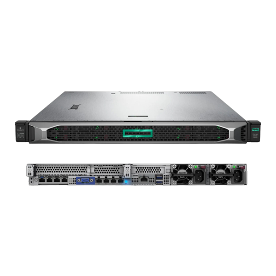
HPE ProLiant DL325 Gen10 Plus Server Maintenance
and Service Guide
Abstract
This guide describes identification and maintenance procedures, diagnostic tools, specifications and requirements for
hardware components and software. This guide is for an experienced service technician. Hewlett Packard Enterprise
assumes that you are qualified in the servicing of computer equipment, trained in recognizing hazards in products, and are
familiar with weight and stability precautions.
Part Number: P18879-004
Published: June 2020
Edition: 4
Advertisement
Table of Contents

Related Manuals for HPE ProLiant DL325 Gen10 Plus


Summary of Contents for HPE ProLiant DL325 Gen10 Plus
- Page 1 HPE ProLiant DL325 Gen10 Plus Server Maintenance and Service Guide Abstract This guide describes identification and maintenance procedures, diagnostic tools, specifications and requirements for hardware components and software. This guide is for an experienced service technician. Hewlett Packard Enterprise assumes that you are qualified in the servicing of computer equipment, trained in recognizing hazards in products, and are familiar with weight and stability precautions.
- Page 2 © Copyright 2019, 2020 Hewlett Packard Enterprise Development LP Notices The information contained herein is subject to change without notice. The only warranties for Hewlett Packard Enterprise products and services are set forth in the express warranty statements accompanying such products and services. Nothing herein should be construed as constituting an additional warranty.
-
Page 3: Table Of Contents
System board assembly spare part..............................13 Controller spare parts....................................14 Trusted Platform Module spare part............................... 14 Server options..........................................14 HPE Smart Storage Battery spare part............................15 Drive backplane spare parts................................. 15 Chassis intrusion detection switch spare part..........................16 Serial port cable spare part................................... 16 OCP NIC 3.0 adapter spare parts.............................. - Page 4 Accessing the product rear panel..............................34 Extending the server from the rack..............................35 Removing the server from the rack..............................37 Removing the inner rack rails................................38 Removing the outer drive cage................................39 Removing an inner drive cage................................42 Removing the access panel................................... 44 Removing the air baffle....................................44 Removing a riser cage....................................
- Page 5 Removing the system board................................105 Replacing the system board................................109 Re-entering the server serial number and product ID......................114 Removing and replacing the chassis intrusion detection switch....................115 HPE Trusted Platform Module 2.0 Gen10 Plus option........................116 Troubleshooting......................117 NMI functionality........................................117 Troubleshooting resources....................................117 Diagnostic tools......................118 Product QuickSpecs.........................................
- Page 6 Environmental specifications....................................164 Mechanical specifications......................................165 Power supply specifications....................................165 HPE 500W Flex Slot Platinum Hot-plug Low Halogen Power Supply..............165 HPE 800W Flex Slot Platinum Hot-plug Low Halogen Power Supply..............166 HPE 800W Flex Slot Titanium Hot-plug Low Halogen Power Supply..............167 HPE 800W Flex Slot Universal Hot-plug Low Halogen Power Supply..............
-
Page 7: Illustrated Parts Catalog
Illustrated parts catalog Mechanical components Hewlett Packard Enterprise continually improves and changes product parts. For complete and current supported spare parts information, see the Hewlett Packard Enterprise PartSurfer website: https://www.hpe.com/info/partssurfer Item Description Access panel spare part Fan blank spare part... -
Page 8: Access Panel Spare Part
Item Description OCP NIC port blank OCP rail spare part Energy pack holder 2SFF drive cage blank ODD blank Bezel spare part Chassis ear spare kit Rail kit spare parts Cable management arm spare part Not shown Access panel spare part Customer self repair: mandatory Description Spare part number... -
Page 9: Power Supply Blank Spare Part
Description Spare part number P23255-001 Air baffle (required only when the high performance fan is installed) Energy pack holder Power supply blank spare part Customer self repair: mandatory Description Spare part number Power supply blank 775423-001 Miscellaneous blank spare kit Customer self repair: mandatory Description Spare part number... -
Page 10: Cable Management Arm Spare Part
Customer self repair: mandatory Description Spare part number 875537-001 Low-profile riser blank System components Hewlett Packard Enterprise continually improves and changes product parts. For complete and current supported spare parts information, see the Hewlett Packard Enterprise PartSurfer website: https://www.hpe.com/info/partssurfer Illustrated parts catalog... -
Page 11: Fan Spare Parts
Heatsink spare parts Processor spare parts System battery spare part Primary riser board spare parts Secondary riser board spare parts HPE 12GB SAS Expander card DIMM spare parts System board assembly spare part Trusted Platform Module spare part Not shown... -
Page 12: Dimm Spare Parts
Description Spare part number Single rotor, standard fan P22813-001 Dual rotor, high performance fan P22814-001 DIMM spare parts Customer self repair: mandatory Description Spare part number 3200 MT/s DIMMs — 8GB, single-rank x8 PC4-3200AA-R P20499-001 16GB, single-rank x8 PC4-3200AA-R P20501-001 16GB, dual-rank x4 PC4-3200AA-R P20500-001 32GB, dual-rank x8 PC4-3200AA-R... -
Page 13: Riser Board Spare Parts
Description Spare part number 2.00GHz AMD EPYC 7702P processor, 64C, 200W-1S P17333-001 2.00GHz AMD EPYC 7662 processor, 64C, 225W-2S P25584-001 2.20GHz AMD EPYC 7552 processor, 48C, 200W-2S P21963-001 2.25GHz AMD EPYC 7742 processor, 64C, 225W-2S P23682-001 2.30GHz AMD EPYC 7352 processor, 24C, 155W-2S P21227-001 2.35GHz AMD EPYC 7452 processor, 32C, 155W-2S P17338-001... -
Page 14: Controller Spare Parts
Spare part number TPM 2.0 with cover 872159-001 For more information, see HPE Trusted Platform Module 2.0 Gen10 Plus option. Server options Hewlett Packard Enterprise continually improves and changes product parts. For complete and current supported spare parts information, see the Hewlett Packard Enterprise PartSurfer website: https://www.hpe.com/info/partssurfer... -
Page 15: Hpe Smart Storage Battery Spare Part
Item Description Drive backplane spare parts Chassis intrusion detection switch spare part HPE Smart Storage Battery spare part Serial port cable spare part OCP NIC 3.0 adapter spare parts Thermal grease spare part Cable spare parts Not shown HPE Smart Storage Battery spare part... -
Page 16: Chassis Intrusion Detection Switch Spare Part
Serial port cable 875571-001 OCP NIC 3.0 adapter spare parts Customer self repair: optional Description Spare part number HPE 1GbE 4-port BASE-T I350-T4 OCP3 Adapter P14487-001 HPE 10GbE 2-port SFP+ QL41132 OCP3 Adapter P11586-001 HPE 10GbE 2-port BASE-T QL41132HQ OCP3 Adapter P13345-001... -
Page 17: Cable Spare Parts
Cable spare parts Customer self repair: optional Description Spare part number LFF front I/O cable kit for short chassis P22825-001 LFF front I/O cable kit for long chassis P22826-001 SFF front I/O cable kit for long chassis P22827-001 SFF front I/O cable kit for short chassis P22828-001 Outer signal cable kit for ODD SATA and 2SFF/uFF to P22821-001... - Page 18 LFF to Smart Array type-a controller cable kit P23259-001 • Short chassis: 4LFF (box 1) to Smart Array controller • Short chassis: 4LFF (box 2) to Smart Array controller • Long chassis: 4LFF (box 1) to Smart Array controller • Long chassis: 4LFF (box 2) to Smart Array controller •...
- Page 19 Long chassis: SFF to 12GB SAS Expander cable kit P23266-001 • 8SFF (box 1, port 1) to Expander • 8SFF (box 1, port 2) to Expander • 8SFF (box 3, port 1) to Expander • 8SFF (box 3, port 2) to Expander •...
- Page 20 8SFF power cable kit P23270-001 • Short chassis: 8SAS/SATA box 1 • Short chassis: 8SAS/SATA box 3 • Long chassis: 8SAS/SATA box 3 • Long chassis: 8SAS/SATA box 5 • Short chassis: U.3 8NVMe box 1 • Short chassis: U.3 8NVMe box 3 •...
-
Page 21: Customer Self Repair
Customer self repair Hewlett Packard Enterprise products are designed with many Customer Self Repair (CSR) parts to minimize repair time and allow for greater flexibility in performing defective parts replacement. If during the diagnosis period Hewlett Packard Enterprise (or Hewlett Packard Enterprise service providers or service partners) identifies that the repair can be accomplished by the use of a CSR part, Hewlett Packard Enterprise will ship that part directly to you for replacement. - Page 22 REMARQUE: Certaines pièces Hewlett Packard Enterprise ne sont pas conçues pour permettre au client d'effectuer lui- même la réparation. Pour que la garantie puisse s'appliquer, Hewlett Packard Enterprise exige que le remplacement de la pièce soit effectué par un Mainteneur Agréé. Ces pièces sont identifiées par la mention "Non" dans le Catalogue illustré. Les pièces CSR sont livrées le jour ouvré...
- Page 23 Per il servizio di garanzia per i soli componenti è obbligatoria la formula CSR che prevede la riparazione da parte del cliente. Se il cliente invece richiede la sostituzione ad Hewlett Packard Enterprise dovrà sostenere le spese di spedizione e di manodopera per il servizio.
- Page 24 • Obligatorio—Componentes cuya reparación por parte del usuario es obligatoria. Si solicita a Hewlett Packard Enterprise que realice la sustitución de estos componentes, tendrá que hacerse cargo de los gastos de desplazamiento y de mano de obra de dicho servicio. Opcional—Componentes cuya reparación por parte del usuario es opcional.
- Page 25 Afhankelijk van de leverbaarheid en de locatie worden CSR-onderdelen verzonden voor levering op de eerstvolgende werkdag. Levering op dezelfde dag of binnen vier uur kan tegen meerkosten worden aangeboden, indien dit mogelijk is gezien de locatie. Indien assistentie is gewenst, belt u het Hewlett Packard Enterprise Support Center om via de telefoon ondersteuning van een technicus te ontvangen.
- Page 26 Serviço de garantia apenas para peças A garantia limitada da Hewlett Packard Enterprise pode incluir um serviço de garantia apenas para peças. Segundo os termos do serviço de garantia apenas para peças, a Hewlett Packard Enterprise fornece as peças de reposição sem cobrar nenhuma taxa.
- Page 27 Customer self repair...
- Page 28 Customer self repair...
- Page 29 Customer self repair...
-
Page 30: Removal And Replacement Procedures
Removal and replacement procedures Required tools Some procedures may require the following tools: • T-25 Torx screwdriver (for screws located inside the front panel quick-release ears) • T-10/T-15/T-20 Torx screwdriver • Flathead screwdriver (for replacing the system battery) Safety considerations Before performing service procedures, review all the safety information. -
Page 31: Server Warnings And Cautions
This symbol on an RJ-45 receptacle indicates a network interface connection. WARNING: To reduce the risk of electric shock, fire, or damage to the equipment, do not plug telephone or telecommunications connectors into this receptacle. This symbol indicates the presence of a hot surface or hot component. If this surface is contacted, the potential for injury exists. -
Page 32: Rack Warnings
WARNING: To reduce the risk of fire or burns after removing the energy pack: • Do not disassemble, crush, or puncture the energy pack. • Do not short external contacts. • Do not dispose of the energy pack in fire or water. After power is disconnected, battery voltage might still be present for 1s to 160s. -
Page 33: Preparation Procedures
WARNING: To reduce the risk of personal injury or damage to the equipment, adequately stabilize the rack before extending a component outside the rack. Extend only one component at a time. A rack may become unstable if more than one component is extended. WARNING: When installing a server in a telco rack, be sure that the rack frame is adequately secured at the top and bottom to the building structure. -
Page 34: Powering Down The Server
To replace the component, reverse the removal procedure. Powering down the server IMPORTANT: When the server is in standby mode, auxiliary power is still being provided to the system. Prerequisites Before powering down the server for any upgrade or maintenance procedures, perform a backup of critical server data and programs. -
Page 35: Extending The Server From The Rack
Extending the server from the rack To perform this procedure, you will need a T-25 screwdriver. WARNING: To reduce the risk of personal injury or equipment damage, be sure that the rack is adequately stabilized before extending a component from the rack. Procedure 1. - Page 36 e. Remove the cable management arm. 2. Extend the server from the rack: a. Open the latches on both sides of the server. b. If necessary, use a T-25 Torx screwdriver to loosen the shipping screws. c. Slide the server out of the rack. Removal and replacement procedures...
-
Page 37: Removing The Server From The Rack
3. Extend the server on the rack rails until the server rail-release latches engage. Removing the server from the rack WARNING: This server is heavy. To reduce the risk of personal injury or damage to the equipment: • Observe local occupational health and safety requirements and guidelines for manual material handling. •... -
Page 38: Removing The Inner Rack Rails
5. Place the server on a sturdy, level surface. Removing the inner rack rails Prerequisites Before you perform this procedure, make sure that you have a T-10 Torx screwdriver available. Procedure 1. If installed, remove the bezel. 2. Power down the server. 3. -
Page 39: Removing The Outer Drive Cage
Removing the outer drive cage Prerequisites Before you perform this procedure, make sure that you have a T-10 Torx screwdriver available. Procedure If installed, remove the bezel. Power down the server. Remove all power: a. Disconnect each power cord from the power source. b. - Page 40 10. Remove the inner drive cage blank. 11. Remove the fan wall covers. 12. For SFF drive cage, remove the cable covers. Removal and replacement procedures...
- Page 41 13. Remove the drive cage latches. 14. Remove the outer drive cage. • Removal and replacement procedures...
-
Page 42: Removing An Inner Drive Cage
• Removing an inner drive cage Prerequisites Before you perform this procedure, make sure that you have a T-10 Torx screwdriver available. Procedure If installed, remove the bezel. Power down the server. Remove all power: Removal and replacement procedures... - Page 43 a. Disconnect each power cord from the power source. b. Disconnect each power cord from the server. Disconnect all peripheral cables from the server. Remove the server from the rack. Remove the inner rack rails. Remove the access panel. Disconnect all drive backplane cables connected to the system board or expansion boards. Remove the fan wall covers.
-
Page 44: Removing The Access Panel
Removing the access panel CAUTION: Do not operate the server for long periods with the access panel open or removed. Operating the server in this manner results in improper airflow and improper cooling that can lead to thermal damage. Prerequisites Before you perform this procedure, make sure that you have a T-15 Torx screwdriver available. -
Page 45: Removing A Riser Cage
Procedure 1. If installed, remove the bezel. 2. Power down the server. 3. Remove all power: a. Disconnect each power cord from the power source. b. Disconnect each power cord from the server. 4. Disconnect all peripheral cables from the server. 5. -
Page 46: Installing The Air Baffle
a. Disconnect each power cord from the power source. b. Disconnect each power cord from the server. 4. Disconnect all peripheral cables from the server. 5. Remove the server from the rack. 6. Remove the access panel. 7. If installed, disconnect all cables from the expansion boards and remove the expansion boards. 8. -
Page 47: Installing The Access Panel
3. Install the access panel. 4. Install the server into the rack. 5. Connect all peripheral cables to the server. 6. Connect each power cord to the server. 7. Connect each power cord to the power source. 8. Power up the server. 9. -
Page 48: Installing The Inner Rack Rails
Installing the inner rack rails Prerequisites Before you perform this procedure, make sure that you have a T-10 Torx screwdriver available. Procedure 1. Align the holes on the rack rail with the chassis alignment pins and slide the rails against the chassis wall. 2. -
Page 49: Installing The Server Into The Rack
Installing the server into the rack WARNING: This server is heavy. To reduce the risk of personal injury or damage to the equipment: • Observe local occupational health and safety requirements and guidelines for manual material handling. • Get help to lift and stabilize the product during installation or removal, especially when the product is not fastened to the rails. -
Page 50: Powering Up The Server
3. Connect peripheral devices to the server. For information on identifying connectors, see Rear panel components. 4. Connect the power cord to the rear of the server. 5. Secure the power cord in the cable management arm. 6. Connect the power cord to the power source. Powering up the server Procedure 1. -
Page 51: Removing And Replacing The Rack Rails
2. Install the Kensington security lock. Removing and replacing the rack rails Procedure 1. If installed, remove the bezel. 2. Power down the server. 3. Remove all power: a. Disconnect each power cord from the power source. b. Disconnect each power cord from the server. 4. -
Page 52: Removing And Replacing The Cable Management Arm
To replace the component, reverse the removal procedure. Removing and replacing the cable management arm Procedure 1. If installed, remove the bezel. 2. Power down the server. 3. Remove all power: a. Disconnect each power cord from the power source. b. -
Page 53: Removing And Replacing The Access Panel
To replace the component, reverse the removal procedure. Removing and replacing the access panel CAUTION: Do not operate the server for long periods with the access panel open or removed. Operating the server in this manner results in improper airflow and improper cooling that can lead to thermal damage. Prerequisites Before you perform this procedure, make sure that you have a T-15 Torx screwdriver available. -
Page 54: Removing And Replacing The Air Baffle
To replace the component, reverse the removal procedure. Removing and replacing the air baffle CAUTION: For proper cooling, do not operate the server without the access panel, baffles, expansion slot covers, or blanks installed. If the server supports hot-plug components, minimize the amount of time the access panel is open. Procedure 1. -
Page 55: Removing And Replacing A Fan Blank
To replace the component, reverse the removal procedure. Removing and replacing a fan blank CAUTION: To prevent improper cooling and thermal damage, do not operate the server unless all bays are populated. Procedure 1. Extend the server from the rack. 2. -
Page 56: Removing And Replacing A Fan
2. To remove a drive blank from an inner drive cage, do the following: NOTE: If the HPE designated cable management arm is not installed on the rack, ensure that the cables at the rear of the server are not damaged while extending the server. -
Page 57: Removing And Replacing A Hot-Plug Drive
3. Remove the drive blank. • LFF drive blank • SFF drive blank To replace the component, reverse the removal procedure. Removing and replacing a hot-plug drive CAUTION: To prevent improper cooling and thermal damage, do not operate the server unless all bays are populated with either a component or a blank. - Page 58 3. To remove the hot-plug drive from an inner drive cage, do the following: NOTE: If the HPE designated cable management arm is not installed on the rack, ensure that the cables at the rear of the server are not damaged while extending the server.
-
Page 59: Removing And Replacing A Uff Drive
3. To remove the drive from an inner drive cage, do the following: NOTE: If the HPE designated cable management arm is not installed on the rack, ensure that the cables at the rear of the server are not damaged while extending the server. - Page 60 4. Observe the LED status of the drive and determine if it can be removed. 5. Remove the drive. To remove the drive carrier: Removal and replacement procedures...
-
Page 61: Removing And Replacing An M.2 Ssd
To replace the component, reverse the removal procedure. Removing and replacing an M.2 SSD This procedure is for drives on the system board, riser, or expansion card. NOTE: Do not perform this procedure on uFF drives. Prerequisites Before you perform this procedure, make sure that you have the following items available: •... -
Page 62: Drive Backplanes
To replace the component, reverse the removal procedure. Drive backplanes Removing and replacing the 4LFF SAS/SATA drive backplane Prerequisites Before you perform this procedure, make sure that you have a T-10 Torx screwdriver available. Procedure If installed, remove the bezel. Power down the server. -
Page 63: Removing And Replacing An 8Sff Sas/Sata Or Nvme Drive Backplane
a. If installed, remove the inner drive cage. b. Remove the outer drive cage. • To replace the drive backplane of the inner drive cage (box 2), remove the inner drive cage. 11. Disconnect all cables from the 4LFF drive backplane. 12. - Page 64 a. Disconnect each power cord from the power source. b. Disconnect each power cord from the server. Disconnect all peripheral cables from the server. Remove the server from the rack. Remove the inner rack rails. Remove the access panel. Remove all drives connected to the drive backplane. Disconnect all drive backplane cables to system board, controller card, or riser.
-
Page 65: Removing And Replacing A 2Sff Sas/Sata, Uff, Or Nvme Drive Backplane
• Outer drive cage • Inner drive cage To replace the component, reverse the removal procedure. Removing and replacing a 2SFF SAS/SATA, uFF, or NVMe drive backplane Prerequisites Before you perform this procedure, make sure that you have T-10 Torx screwdriver available. Procedure If installed, remove the bezel. - Page 66 • Remove SAS/SATA, or NVMe drives. • Remove uFF drives. Disconnect all drive backplane cables to system board, controller card, or riser. 10. Do one of the following: • To replace the drive backplane of the outer drive cage (box 2): a.
-
Page 67: Removing And Replacing An Expansion Board
• Inner drive cage a. Remove the bracket screw from the cage. NOTE: The screw is on the top side of the cage. b. Slide the bracket away from the backplane. c. Slide and pull out the backplane. To replace the component, reverse the removal procedure. Removing and replacing an expansion board Prerequisites Before you perform this procedure, make sure that you have T-15 Torx screwdriver available. - Page 68 4. Disconnect all peripheral cables from the server. 5. Remove the server from the rack. 6. Remove the access panel. 7. If present, disconnect all cables from the expansion board. 8. If replacing the expansion board from the primary riser, remove the primary riser cage. 9.
-
Page 69: Removing And Replacing The Gpu
• Secondary riser slot 3: full height To replace the component, reverse the removal procedure. Removing and replacing the GPU Prerequisites Before you perform this procedure, make sure that you have T-15 Torx screwdriver available. Procedure 1. If installed, remove the bezel. 2. - Page 70 a. Disconnect each power cord from the power source. b. Disconnect each power cord from the server. 4. Disconnect all peripheral cables from the server. 5. Remove the server from the rack. 6. Remove the access panel. 7. If replacing the GPU from the primary riser, remove the primary riser cage. 8.
-
Page 71: Removing And Replacing The Low-Profile Riser Blank
To replace the GPU in primary riser slot 1, install the full-height bracket on the GPU if not installed already. The screw type and location shown in the illustration might be different depending on the GPU option. To replace the component, reverse the removal procedure. Removing and replacing the low-profile riser blank Prerequisites Before you perform this procedure, make sure that you have T-15 Torx screwdriver available. -
Page 72: Removing And Replacing A Riser Board
a. Disconnect each power cord from the power source. b. Disconnect each power cord from the server. 4. Disconnect all peripheral cables from the server. 5. Remove the server from the rack. 6. Remove the access panel. 7. Remove the low-profile riser blank. To replace the component, reverse the removal procedure. -
Page 73: Removing And Replacing The Smart Array Type-A Modular Controller Or 1-Port Nvme Adapter
If installed, remove expansion board from the secondary riser cage. Remove the riser cage. 10. If installed, remove all expansion boards from the primary riser board. 11. Remove the riser board. • Primary riser board • Secondary riser board To replace the component, reverse the removal procedure. Removing and replacing the Smart Array type-a modular controller or 1-port NVMe adapter Procedure... -
Page 74: Removing And Replacing An Energy Pack
7. Disconnect all cables from the type-a controller or 1-port NVMe adapter. 8. Remove the type-a modular controller or 1-port NVMe adapter. To replace the component, reverse the removal procedure. Removing and replacing an energy pack Procedure 1. If installed, remove the bezel. 2. -
Page 75: Removing And Replacing The Energy Pack Holder
To replace the component, reverse the removal procedure. Removing and replacing the energy pack holder Procedure 1. If installed, remove the bezel. 2. Power down the server. 3. Remove all power: a. Disconnect each power cord from the power source. b. -
Page 76: Removing And Replacing The Optical Drive Blank
To replace the component, reverse the removal procedure. Removing and replacing the optical drive blank Prerequisites Before you perform this procedure, make sure that you have T-10 Torx screwdriver available. Procedure 1. If installed, remove the bezel. 2. Power down the server. 3. - Page 77 • a. Remove the optical drive cage. b. Remove the blank. Removal and replacement procedures...
-
Page 78: Removing And Replacing The Optical Drive
To replace the component, reverse the removal procedure. Removing and replacing the optical drive Prerequisites Before you perform this procedure, make sure that you have T-10 Torx screwdriver available. Procedure 1. If installed, remove the bezel. 2. Power down the server. 3. - Page 79 a. Remove the outer drive cage cover. b. Disconnect all cables from the optical drive c. Remove the optical drive. • a. Do one of the following: Remove the inner drive cage. ◦ ◦ Remove the inner drive cage blank. b.
-
Page 80: Removing And Replacing A Chassis Ear
To replace the component, reverse the removal procedure. Removing and replacing a chassis ear Prerequisites Before you perform this procedure, make sure that you have an electric screwdriver available. Procedure 1. If installed, remove the bezel. 2. Extend the server from the rack. 3. - Page 81 • Left ear Before installing the new ear, install a spring and a screw in the ear and attach the label to the front of the ear. To replace the component, reverse the removal procedure. Removal and replacement procedures...
-
Page 82: Removing And Replacing The Lff Front I/O Assembly
Removing and replacing the LFF front I/O assembly Prerequisites Before you perform this procedure, make sure that you have the T-10 screwdriver available. Procedure If installed, remove the bezel. Power down the server. Remove all power: a. Disconnect each power cord from the power source. b. -
Page 83: Removing And Replacing The Sff Front I/O Assembly
a. Remove screws. b. Detach the ambient thermal sensor cable from its clip. c. Remove the front I/O module. To replace the component, reverse the removal procedure. Removing and replacing the SFF front I/O assembly Prerequisites Before you perform this procedure, make sure that you have the following tools available. •... - Page 84 Disconnect the front I/O cable from system board. Do one of the following: Remove the inner drive cage. • • Remove the inner drive cage blank. 10. Remove cable covers. 11. Remove the front I/O module. Removal and replacement procedures...
-
Page 85: Removing And Replacing The Ocp Nic 3.0 Adapter
12. Remove the front I/O cables. To replace the component, reverse the removal procedure. Removing and replacing the OCP NIC 3.0 adapter WARNING: To reduce the risk of personal injury from hot surfaces, allow the drives and the internal system components to cool before touching them. -
Page 86: Removing And Replacing The Ocp Nic 3.0 Adapter Rails
Procedure 1. If installed, remove the bezel. 2. Power down the server. 3. Remove all power: a. Disconnect each power cord from the power source. b. Disconnect each power cord from the server. 4. Disconnect all peripheral cables from the server. 5. - Page 87 Prerequisites Before you perform this procedure, make sure that you have a T-10 Torx screwdriver available. Procedure If installed, remove the bezel. Power down the server. Remove all power: a. Disconnect each power cord from the power source. b. Disconnect each power cord from the server. Disconnect all peripheral cables from the server.
-
Page 88: Removing And Replacing The Serial Port Cable
To replace the component, reverse the removal procedure. Removing and replacing the serial port cable Prerequisites Before you perform this procedure, make sure that you have a nut screwdriver available. Procedure 1. If installed, remove the bezel. 2. Power down the server. 3. -
Page 89: Removing And Replacing A Power Supply Blank
To replace the component, reverse the removal procedure. Removing and replacing a power supply blank CAUTION: To prevent improper cooling and thermal damage, do not operate the server unless all bays are populated. Procedure Remove the power supply blank from the power supply bay. To replace the component, reverse the removal procedure. -
Page 90: Removing And Replacing A Flexible Slot Power Supply
Removing and replacing a Flexible Slot power supply WARNING: To reduce the risk of personal injury from hot surfaces, allow the power supply or power supply blank to cool before touching it. CAUTION: To prevent improper cooling and thermal damage, do not operate the server unless all bays are populated with either a component or a blank. - Page 91 • DC power supply 3. For an AC power supply, do the following: a. Disconnect the power cord from the power supply. Removal and replacement procedures...
- Page 92 b. Remove the power supply. 4. For a DC power supply, do the following: a. Slide the power supply out of the bay just enough to access the ground cable screw. b. Detach the ground (earthed) cable from the power supply. Removal and replacement procedures...
- Page 93 c. Remove the terminal block connector from the power supply. d. Remove the power supply. Removal and replacement procedures...
-
Page 94: Removing And Replacing A Heatsink
To replace the component, reverse the removal procedure. Removing and replacing a heatsink Removing a heatsink This procedure shows a standard heatsink as an example. The removal process is the same for both the standard and high performance heatsinks. Prerequisites Before you perform this procedure, make sure that you have a T-20 Torx screwdriver available. -
Page 95: Replacing A Heatsink
Allow the existing heatsink to cool. 10. Remove the heatsink: CAUTION: To prevent mechanical damage or depositing oil on your hands or other contaminant to the heatsink contact surface, hold the heatsink only by the edge of its base plate. Do not touch the heatsink fins. CAUTION: Heatsink screws must be tightened and loosened in alternating sequence. - Page 96 Allow the alcohol to evaporate before continuing. Remove the thermal interface protective cover from the new heatsink. Install the heatsink: CAUTION: To prevent mechanical damage or depositing oil on your hands or other contaminant to the heatsink contact surface, hold the heatsink only by the edge of its base plate. Do not touch the heatsink fins. CAUTION: To prevent thermal failure or component damage, do not move the heatsink once the bottom of its base plate touches the top of the processor.
-
Page 97: Removing And Replacing A Processor
Removing and replacing a processor Removing a processor Hewlett Packard Enterprise recommends identifying the processor and socket components before performing this procedure. Prerequisites Before you perform this procedure, make sure that you have the following items available: • T-20 Torx screwdriver •... - Page 98 a. Use a T-20 Torx screwdriver to loosen the captive screws in the sequence specified on the heatsink label. b. Lift the heatsink away from the system board. c. Place the heatsink on a flat work surface with its contact side facing upward. 11.
-
Page 99: Replacing A Processor
Replacing a processor Hewlett Packard Enterprise recommends identifying the processor and socket components before performing this procedure. Prerequisites Before you perform this procedure, make sure that you have the following items available: • The components included with the hardware option kit •... - Page 100 A click sound indicates that the rail frame is properly engaged. Close the force frame: CAUTION: Do not overtighten the screws as this might damage the system board or the processor socket. a. Pivot the spring loaded force frame downward and hold it down (callout 1). b.
- Page 101 Install the heatsink: CAUTION: To prevent mechanical damage or depositing oil on your hands or other contaminant to the heatsink contact surface, hold the heatsink only by the edge of its base plate. Do not touch the heatsink fins. CAUTION: To prevent thermal failure or component damage, do not move the heatsink once the bottom of its base plate touches the top of the processor.
-
Page 102: System Battery Replacement
If removed, install the air baffle. Install the access panel. Install the server into the rack. Connect all peripheral cables to the server. 10. Connect each power cord to the server. 11. Connect each power cord to the power source. 12. -
Page 103: Removing And Replacing The System Battery
Removing and replacing the system battery Procedure If installed, remove the bezel. Power down the server. Remove all power: a. Disconnect each power cord from the power source. b. Disconnect each power cord from the server. Disconnect all peripheral cables from the server. Remove the server from the rack. -
Page 104: Removing And Replacing A Dimm
11. Install the server into the rack. 12. Connect all peripheral cables to the server. 13. Connect each power cord to the server. 14. Connect each power cord to the power source. 15. Power up the server. 16. If removed, install the bezel. 17. -
Page 105: Removing And Replacing The System Board
12. Remove all fan blanks. 13. If installed, remove the following components: Smart Array modular type-a controller or 1-port NVMe adapter • • HPE Smart Storage battery • OCP NIC 3.0 adapter Serial port cable • Chassis intrusion detection switch •... - Page 106 15. Remove the left OCP NIC 3.0 adapter rail. 16. Remove all DIMMs. 17. Allow the existing heatsink to cool. 18. Remove the heatsink: CAUTION: To prevent mechanical damage or depositing oil on your hands or other contaminant to the heatsink contact surface, hold the heatsink only by the edge of its base plate.
- Page 107 c. Place the heatsink on a flat work surface with its contact side facing upward. 19. Use an alcohol wipe to remove the existing thermal grease from the heatsink. Allow the alcohol to evaporate before continuing. 20. Use a T-20 Torx screwdriver to loosen the three captive screws in the sequence shown in the following image, and then pivot the force frame upward.
- Page 108 22. Use an alcohol wipe to remove the existing thermal grease from the processor. Allow the alcohol to evaporate before continuing. 23. Remove the system board with the base pan: a. Install the system board handle on the corner of the processor socket. b.
-
Page 109: Replacing The System Board
b. Remove all screws from the system board. 25. Remove the right OCP NIC 3.0 adapter rail. 26. Remove the handle from the system board. Replacing the system board Prerequisites Before you perform this procedure, make sure that you have the following items available: •... - Page 110 b. Remove all screws from the system board. c. Install the right OCP NIC 3.0 adapter rail. Install the new system board with the base pan: a. Install the system board handle on the corner of the processor socket. b. Hold the handle and the thumbscrew to place the new system board in the chassis. NOTE: Ensure that the alignment mark is visible on the corner after installing the system board.
- Page 111 Install the system board screws. Install the VGA screws. Use a T-20 Torx screwdriver to loosen the three captive screws in the sequence shown in the following image, and then pivot the force frame upward. Remove the external cap: a. Hold the lift tabs near the front end of the rail frame, and then pivot the rail frame to the vertical position. b.
- Page 112 Close the force frame: CAUTION: Do not overtighten the screws as this might damage the system board or the processor socket. a. Pivot the spring loaded force frame downward and hold it down (callout 1). b. Use a T-20 Torx screwdriver to tighten the captive screws in the sequence shown in the following image (callouts 2–4).
- Page 113 11. Install the heatsink: CAUTION: To prevent mechanical damage or depositing oil on your hands or other contaminant to the heatsink contact surface, hold the heatsink only by the edge of its base plate. Do not touch the heatsink fins. CAUTION: To prevent thermal failure or component damage, do not move the heatsink once the bottom of its base plate touches the top of the processor.
-
Page 114: Re-Entering The Server Serial Number And Product Id
12. Install all the components removed from the system board. 13. If removed, install the air baffle. 14. Install the access panel. 15. Install the server into the rack. 16. Connect all peripheral cables to the server, 17. Connect each power cord to the server. 18. -
Page 115: Removing And Replacing The Chassis Intrusion Detection Switch
4. To clear the warning, press the Enter key. 5. Enter the serial number and press the Enter key. 6. Select Product ID. The following warning appears: Warning: The Product ID should ONLY be modified by qualified service personnel. This value should always match the Product ID located on the chassis. -
Page 116: Hpe Trusted Platform Module 2.0 Gen10 Plus Option
HPE Trusted Platform Module 2.0 Gen10 Plus option The HPE Trusted Platform Module 2.0 Gen10 Plus option is not a customer-removable part. CAUTION: If the TPM is removed from the original server and powered up on a different server, data stored in the TPM including keys will be erased. -
Page 117: Troubleshooting
Error Message Guide for HPE ProLiant Gen10 servers and HPE Synergy provides a list of error messages and information to assist with interpreting and resolving error messages. • Error Message Guide for HPE ProLiant Gen10 Plus servers and HPE Synergy provides a list of error messages and information to assist with interpreting and resolving error messages. •... -
Page 118: Diagnostic Tools
Product QuickSpecs For more information about product features, specifications, options, configurations, and compatibility, see the product QuickSpecs on the Hewlett Packard Enterprise website (https://www.hpe.com/info/qs). UEFI System Utilities The UEFI System Utilities is embedded in the system ROM. Its features enable you to perform a wide range of configuration activities, including: •... -
Page 119: Secure Boot
Operating systems must support Secure Boot and have an EFI boot loader signed with one of the authorized keys to boot. For more information about supported operating systems, see https://www.hpe.com/servers/ossupport. You can customize the certificates embedded in the UEFI BIOS by adding or removing your own certificates, either from a management console directly attached to the server, or by remotely connecting to the server using the iLO Remote Console. -
Page 120: Ilo Service Port
You cannot access the connected device from the server. Intelligent Provisioning Intelligent Provisioning is a single-server deployment tool embedded in ProLiant servers and HPE Synergy compute modules. Intelligent Provisioning simplifies server setup, providing a reliable and consistent way to deploy servers. -
Page 121: Intelligent Provisioning Operation
Intelligent Provisioning 3.30 and later includes HPE Rapid Setup Software. When you launch F10 mode from the POST screen, you are prompted to select whether you want to enter the Intelligent Provisioning or HPE Rapid Setup Software mode. NOTE: After you have selected a mode, you must reprovision the server to change the mode that launches when you boot to F10. -
Page 122: Hpe Insight Remote Support
Packard Enterprise Warranty, HPE support services, or Hewlett Packard Enterprise contractual support agreement. HPE InfoSight for servers The HPE InfoSight portal is a secure web interface hosted by HPE that allows you to monitor supported devices through a graphical interface. -
Page 123: Hpe Smart Storage Administrator
HPE Smart Storage Administrator HPE SSA is the main tool for configuring arrays on HPE Smart Array SR controllers. It exists in three interface formats: the HPE SSA GUI, the HPE SSA CLI, and HPE SSA Scripting. All formats provide support for configuration tasks. Some of the advanced tasks are available in only one format. -
Page 124: Component Identification
Component identification Front panel components LFF drive model Item Description Optical drive (optional, for short chassis only) Serial label pull tab iLO service port USB 3.0 port LFF drive bays (up to 12 LFF drives) SFF SAS/SATA/U.3 NVMe drive model Item Description Serial label pull tab... - Page 125 Item Description 2SFF SAS/SATA/U.3 NVMe drive cage (optional, for short chassis only) 2SFF dual uFF M.2 drive cage (optional, for short chassis only) 2SFF U.2 NVMe drive cage (optional, cage 1 only) Media bay blank USB 3.0 port iLO service port SFF drive bays (up to 24 SAS/SATA/U.3 NVMe drives) 2SFF U.2 NVMe is supported with 8SFF SAS/SATA, but not supported with 8SFF U.3 NVMe.
-
Page 126: Serial Number/Ilo Information Pull Tab
The other side shows the default iLO account information and QR code label. Use a mobile device to scan the QR code label to display the server mobile product page (https://www.hpe.com/qref/ dl325gen10plus). This page contains links to server setup information, spare part numbers, QuickSpecs, troubleshooting resources, and other useful product links. -
Page 127: Sff Drive Model
Solid amber = System in standby Off = No power present If the health LED indicates a degraded or critical state, review the system Integrated Management Log (IML) or use HPE iLO to review the system health status. If the system power LED is off, verify the following conditions: •... - Page 128 • The front I/O cable is connected. If the health LED indicates a degraded or critical state, review the system Integrated Management Log (IML) or use HPE iLO to review the system health status. If all LEDs described in this table flash simultaneously, a power fault has occurred. For more information, see "Power fault LEDs".
-
Page 129: Uid Button Functionality
UID button functionality The UID button can be used to display the Server Health Summary when the server will not power on. For more information, see the iLO user guide on the Hewlett Packard Enterprise website (https://www.hpe.com/support/ilo- docs). Front panel LED power fault codes The following table provides a list of power fault codes, and the subsystems that are affected. -
Page 130: Rear Panel Leds
Item Description Video port Small OCP NIC 3.0 slot (optional) For more information, see PCIe expansion slot definitions. Rear panel LEDs Item Status Definition NIC link Green Network link No network link NIC status Solid Green Linked to network Flashing green Network active No network activity Solid blue... -
Page 131: System Board Components
System board components Item Description Serial port connector Secondary PCIe riser connector System maintenance switch Storage controller backup power connector 2 GPU power connector 2 Primary PCIe riser connector System battery NVMe port 6A OCP NIC 3.0 connector OCP X16 upgrade connector Internal USB 3.0 connector Storage controller backup power connector 1 Energy pack connector... -
Page 132: System Maintenance Switch Descriptions
Item Description NVMe port 4A NVMe/SATA port 8A NVMe port 5A Front I/O connector Fan connector 8 GPU power connector 1 Fan connector 7 Fan connector 6 TPM connector Fan connector 5 Fan connector 4 NVMe port 3A NVMe port 1A Fan connector 3 NVMe port 2A Fan connector 2... -
Page 133: Dimm Slot Locations
Position Default Function 1, 2, 3 Off = No function On = Restore default manufacturing settings Reserved — Reserved — Reserved — Reserved — Reserved — Reserved To access the redundant ROM, set S1, S5, and S6 to On. When the system maintenance switch position 6 is set to the On position, the system is prepared to restore all configuration settings to their manufacturing defaults. - Page 134 AA = CAS 26-22-22 (for 3DS LRDIMM) DIMM type R = RDIMM (registered) L = LRDIMM (load reduced) For more information about product features, specifications, options, configurations, and compatibility, see the HPE DDR4 SmartMemory QuickSpecs on the Hewlett Packard Enterprise website (https://www.hpe.com/support/ DDR4SmartMemoryQS). Component identification...
-
Page 135: Processor And Socket Components
Processor and socket components Item Description Pin field Rail frame Carrier frame Processor Force frame Captive screws (Torx T-20) Drive box identification • LFF drive model ◦ Short chassis ◦ Long chassis Component identification... - Page 136 Item Description Box 1 Box 2 Box 3 Optional • SFF drive model ◦ Short chassis ◦ Long chassis NOTE: 2SFF drive cage is not supported in long chassis configuration. Component identification...
-
Page 137: Drive Bay Numbering
Item Description Box 1 Box 2 Box 3 Box 4 Box 5 Optional Drive bay numbering • LFF drive model Box 1 Box 2/Box 3 • SFF drive model Short Chassis - Box 1/Box 2 Drive numbering color Description Green 8SFF SAS/SATA/U.2 or U.3 NVMe drives Orange 2SFF SAS/SATA/U.2 or U.3 NVMe drives (optional) - Page 138 Drive numbering color Description Green 8SFF SAS/SATA/U.2 or U.3 NVMe drives Orange 2SFF SAS/SATA/U.3 NVMe drives (optional) Blue Dual uFF M.2 drives (optional) If 8SFF U.3 NVMe drives are installed in box 3, only 2 SFF U.3 NVMe drives are supported in box 4 using 1-port NVMe adapter due to the cabling limitation.
-
Page 139: Drive Leds And Buttons
Drive LEDs and buttons Low-profile LFF drive LED definitions Item Status Definition Fault Solid amber The drive has failed. \Locate Solid blue The drive is operating normally and being identified by a management application. Flashing amber/blue The drive has failed, or a predictive failure alert has been received for this drive;... -
Page 140: Smart Carrier (Sc) Drive Led Definitions
Smart Carrier (SC) drive LED definitions Item Status Definition Locate Solid blue The drive is being identified by a host application. Flashing blue The drive carrier firmware is being updated or requires an update. Activity Rotating green Drive activity ring No drive activity Do not Solid white... - Page 141 CAUTION: Do not remove an NVMe drive from the drive bay while the Do not remove LED is flashing. The Do not remove LED flashes to indicate that the device is still in use. Removing the NVMe drive before the device has completed and ceased signal/traffic flow can cause loss of data.
-
Page 142: Uff Drive Components And Leds
Item Status Definition Flashing green The drive ejection request is pending. The drive has been ejected. uFF drive components and LEDs Item Description Status Locate • Off—Normal • Solid blue—The drive is being identified by a host application • Flashing blue—The drive firmware is being updated or requires an update uFF drive ejection latch Removes the uFF drive when released... -
Page 143: Pcie Expansion Slot Definitions
Half-height/half-length Full-height/half-length HPE Smart Array plug-in controller is not supported in slot 1 due to the cable limitation. Slot 2 is not available when a slimline primary riser or full-height secondary riser is installed. Slot 3 is not available when a slimline secondary riser is installed. -
Page 144: Riser Board Components
Item Description Definition Each PCIe version corresponds to a specific data transfer rate PCI Express version between the processor and peripheral devices. Generally, a version update corresponds to an increase in transfer rate. • PCIe 1.x • PCIe 2.x • PCIe 3.x •... -
Page 145: Fan Bay Numbering
Slimline primary riser Item Description PCIe4 x16 (16, 8, 4, 1) slot Slimline connectors Standard secondary riser Item Description PCIe4 x16 (16, 8, 4, 1) slot Slimline secondary riser Item Description 1 -2 Slimline connectors Fan bay numbering The arrow points to the front of the server. Component identification... -
Page 146: Cabling
Cabling Cabling guidelines The cable colors in the cabling diagrams used in this chapter are for illustration purposes only. Observe the following guidelines when working with server cables. Before connecting cables • Note the port labels on the PCA components. Not all these components are used by all servers: ◦... -
Page 147: Cable Routing: 4/8Lff Drive Model
Cable routing: 4/8LFF drive model • 4LFF SATA drives (box 1) connected to system board • 4LFF SAS/SATA drives (box 1) connected to HPE Smart Array type-a modular controller Cabling... - Page 148 • 8LFF SATA drives (box 1 and 2) connected to system board • 8LFF SAS/SATA drives (box 1 and 2) connected to HPE Smart Array type-a modular controller Cabling...
-
Page 149: Cable Routing: 8/16/20Sff Sas/Sata Drive Model
Power cable from box 2 drive backplane to system board power connector 3 Cable routing: 8/16/20SFF SAS/SATA drive model • 8SFF SATA drives (box 1) connected to system board • 8SFF SAS/SATA drives (box 1) connected to HPE Smart Array type-a modular controller Cabling... - Page 150 Mini-SAS cable from box 1 drive backplane port 1 to type-a controllerport 1 Blue Mini-SAS cable from box 1 drive backplane port 2 to type-a controller port 2 • 10SFF SAS/SATA drives (box 1 and 2) connected to HPE Smart Array type-a modular controller, P816i-a Cable color Description Orange...
- Page 151 Mini-SAS cable from box 3 drive backplane port 1 to type-a controller port 3 Pink Mini-SAS cable from box 3 drive backplane port 2 to type-a controller port 4 • 20SFF SAS/SATA Configuration ◦ 16SFF SAS/SATA drives (box 1 and 3) connected to SAS expander and HPE Smart Array type-a modular controller Cabling...
- Page 152 Cable color Description Orange Mini-SAS cable from SAS expander port 3 to box 1 drive backplane port 1 Blue Mini-SAS cable from SAS expander port 4 to box 1 drive backplane port 2 Gold Mini-SAS cable from SAS expander port 6 to box 3 drive backplane port 1 Pink Mini-SAS cable from SAS expander port 7 to box 3 drive backplane port 2 Green...
-
Page 153: Cable Routing: 8/16Sff U.2/U.3 Nvme Drive Model
Cable color Description Orange Power cable from box 1 drive backplane to system board power connector 1 Blue Power cable from box 3 drive backplane to system board power connector 2 Gold Power cable from box 1 8SFF drive backplane to box 2 2SFF drive backplane Pink Power cable from box 3 8SFF drive backplane to box 4 2SFF drive backplane Cable routing: 8/16SFF U.2/U.3 NVMe drive model... - Page 154 Item Description Orange Slimline cable from box 3 drive backplane port 1 to NVMe port 7A on 1-port NVMe adapter Blue Slimline cable from box 3 drive backplane port 2 to NVMe port 2A on system board Gold Slimline cable from box 3 drive backplane port 3 to NVMe port 4A on system board Pink Slimline cable from box 3 drive backplane port 4 to NVMe port 6A on system board •...
- Page 155 Item Description Orange Slimline cable from box 3 drive backplane port 1 to port 2B on secondary riser Blue Slimline cable from box 3 drive backplane port 2 to port 1B on secondary riser Gold Slimline cable from box 3 drive backplane port 3 to port 2A on system board Pink Slimline cable from box 3 drive backplane port 4 to port 6A on system board Green...
-
Page 156: Cable Routing: 2Sff/2+2Sff Sas/Sata/Uff Drives
Item Description Pink Slimline cable from box 4 drive backplane port 1 to port 7A on 1-port NVMe adapter Green OCP x16 cable from OCP x16 connector to port 6A on system board • Power cabling Cable routing: 2SFF/2+2SFF SAS/SATA/uFF drives •... - Page 157 • 2+2SFF SAS/SATA/uFF drives installed in outer and inner cages (box 2 and 4) and connected to system board • 2+2SFF SAS/SATA drives installed in outer and inner cages (box 2 and 4) and connected to type-p storage controller This illustration shows the cabling for type-p storage controller installed in slot 2. The cabling for type-p storage controller installed in slot 3 is similar.
-
Page 158: Cable Routing: 2Sff Nvme/2+2Sff Nvme Drives
Cable color Description Orange Mini-SAS cable from box 2 drive backplane port 1 to type-p controller port 1 Blue Mini-SAS cable from box 4 drive backplane port 1 to type-p controller port 2 • Power cabling Cable color Description Orange Power cable from box 1 8SFF drive backplane to box 2 2SFF drive backplane Blue Power cable from box 3 8SFF drive backplane to box 4 2SFF drive backplane... -
Page 159: Cable Routing: Optical Drive
NOTE: For 20SFF U.3 NVMe configuration, the 2SFF U.3 NVMe drives installed in inner cage (box 4) are connected to 1-port NVMe adapter. Cable color Description Orange Slimline SAS cable from box 2 drive backplane port 1 to system board port 4A Blue Slimline SAS cable from box 4 drive backplane port 1 to system board port 5A Power cabling... -
Page 160: Cable Routing: Front I/O
Cable routing: Front I/O • • Cabling... -
Page 161: Cable Routing: Serial Port
Cable routing: Serial port Cable routing: Chassis intrusion detection switch Cabling... -
Page 162: Cable Routing: M.2 Enablement Board
Cable routing: M.2 enablement board This illustration shows the cabling for M.2 enablement board installed in slot 3. The cabling for M.2 enablement board installed in slot 1 or 2 is similar. Cable routing: Controller backup power cable This illustration shows the cabling for type-p controller installed in slot 2. The cabling for type-p controller installed in slot 3 is similar. -
Page 163: Cable Routing: Energy Pack
Cable routing: Energy pack Cable routing: OCP x16 NIC adapter Cabling... -
Page 164: Specifications
Specifications Environmental specifications Specifications Value Temperature range* — Operating 10°C to 35°C (50°F to 95°F) Nonoperating -30°C to 60°C (-22°F to 140°F) Relative humidity (noncondensing) — Operating 8% to 90% - Relative humidity (Rh), 28°C (82.4°F) maximum wet bulb temperature, non-condensing Nonoperating 5 to 95% relative humidity (Rh), 38.7°C (101.7°F) maximum wet bulb temperature, non-condensing... -
Page 165: Mechanical Specifications
Power supply specifications Depending on the installed options and the regional location where the server was purchased, the server can be configured with one of the following power supplies: HPE 500W Flex Slot Platinum Hot-plug Low Halogen Power Supply • •... -
Page 166: Hpe 800W Flex Slot Platinum Hot-Plug Low Halogen Power Supply
500 W at 100 VAC to 127 VAC input 500 W at 100 VAC to 240 VAC input 500 W at 240 VDC input for China only HPE 800W Flex Slot Platinum Hot-plug Low Halogen Power Supply Specification Value Input requirements —... -
Page 167: Hpe 800W Flex Slot Titanium Hot-Plug Low Halogen Power Supply
800 W at 100 VAC to 127 VAC input 800 W at 100 VAC to 240 VAC input 800 W at 240 VDC input for China only HPE 800W Flex Slot Titanium Hot-plug Low Halogen Power Supply Specification Value Input requirements —... -
Page 168: Hpe 800W Flex Slot Universal Hot-Plug Low Halogen Power Supply
800 W at 240 VDC input for China only Maximum peak power 800 W at 200 VAC to 240 VAC input 800 W at 240 VDC input for China only HPE 800W Flex Slot Universal Hot-plug Low Halogen Power Supply Specification Value Input requirements —... -
Page 169: Hpe 800W Flex Slot -48Vdc Hot-Plug Low Halogen Power Supply
HPE 800W Flex Slot -48VDC Hot-plug Low Halogen Power Supply Specification Value Input requirements — Rated input voltage -40 VDC to -72 VDC -48 VDC nominal input Rated input current 22.1 A at -40 VDC input 18.2 A at -48 VDC input, nominal input 12.0 A at -72 VDC input... -
Page 170: Hpe 1600W Flex Slot Platinum Hot-Plug Low Halogen Power Supply
• Switching or disconnecting devices must not be in the earthed circuit conductor between the DC source and the point of connection of the earthing electrode conductor. HPE 1600W Flex Slot Platinum Hot-plug Low Halogen Power Supply Specification Value Input requirements... -
Page 171: Websites
Storage white papers and analyst reports https://www.hpe.com/storage/whitepapers For additional websites, see Support and other resources. Product websites HPE ProLiant DL325 Gen10 Plus Server product page https://www.hpe.com/servers/dl325-gen10plus HPE ProLiant DL325 Gen10 Plus Server support page https://www.hpe.com/support/dl325gen10plus HPE ProLiant DL325 Gen10 Plus Server user documents https://www.hpe.com/info/dl325gen10plus-docs... -
Page 172: Support And Other Resources
• To download product updates: Hewlett Packard Enterprise Support Center https://www.hpe.com/support/hpesc Hewlett Packard Enterprise Support Center: Software downloads https://www.hpe.com/support/downloads My HPE Software Center https://www.hpe.com/software/hpesoftwarecenter • To subscribe to eNewsletters and alerts: https://www.hpe.com/support/e-updates • To view and update your entitlements, and to link your contracts and warranties with your profile, go to the Hewlett Packard Enterprise Support Center More Information on Access to Support Materials page: https://www.hpe.com/support/AccessToSupportMaterials... -
Page 173: Remote Support
IMPORTANT: Access to some updates might require product entitlement when accessed through the Hewlett Packard Enterprise Support Center. You must have an HPE Passport set up with relevant entitlements. Remote support Remote support is available with supported devices as part of your warranty or contractual support agreement. It provides intelligent event diagnosis, and automatic, secure submission of hardware event notifications to Hewlett Packard Enterprise, which will initiate a fast and accurate resolution based on your product's service level. -
Page 174: Documentation Feedback
Hewlett Packard Enterprise is committed to providing documentation that meets your needs. To help us improve the documentation, send any errors, suggestions, or comments to Documentation Feedback (docsfeedback@hpe.com). When submitting your feedback, include the document title, part number, edition, and publication date located on the front cover of the document.
Need help?
Do you have a question about the ProLiant DL325 Gen10 Plus and is the answer not in the manual?
Questions and answers