Table of Contents
Advertisement
Quick Links
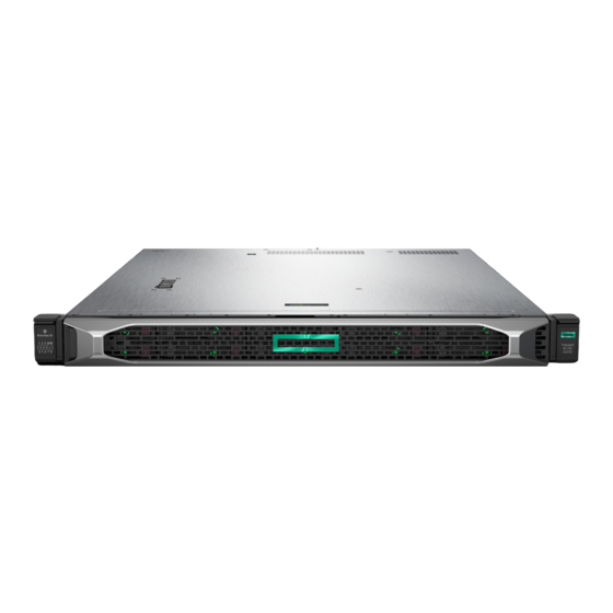
HPE ProLiant DL325 Gen10 Server
Maintenance and Service Guide
Abstract
This guide describes identification and maintenance procedures, diagnostic tools,
specifications and requirements for hardware components and software. This guide is for an
experienced service technician. Hewlett Packard Enterprise assumes that you are qualified in
the servicing of computer equipment, trained in recognizing hazards in products, and are
familiar with weight and stability precautions.
Part Number: P02216-003
Published: April 2019
Edition: 3
Advertisement
Table of Contents

Related Manuals for HPE ProLiant DL325


Summary of Contents for HPE ProLiant DL325
- Page 1 HPE ProLiant DL325 Gen10 Server Maintenance and Service Guide Abstract This guide describes identification and maintenance procedures, diagnostic tools, specifications and requirements for hardware components and software. This guide is for an experienced service technician. Hewlett Packard Enterprise assumes that you are qualified in the servicing of computer equipment, trained in recognizing hazards in products, and are familiar with weight and stability precautions.
- Page 2 © Copyright 2018–2019 Hewlett Packard Enterprise Development LP Notices The information contained herein is subject to change without notice. The only warranties for Hewlett Packard Enterprise products and services are set forth in the express warranty statements accompanying such products and services. Nothing herein should be construed as constituting an additional warranty. Hewlett Packard Enterprise shall not be liable for technical or editorial errors or omissions contained herein.
-
Page 3: Table Of Contents
Serial port cable spare part....................24 iLO service port spare part....................25 USB 3.0 and SFF front I/O cable kit spare part..............25 Cable spare parts......................25 HPE Trusted Platform Module 2.0 spare part..............26 Thermal grease spare part....................26 Removal and replacement procedures..........27 Required tools..........................27 Safety considerations........................27... - Page 4 Replacing the system board.....................82 Re-entering the server serial number and product ID............85 Removing and replacing the system battery................86 Removing and replacing the Chassis Intrusion Detection switch..........87 HPE Trusted Platform Module 2.0 Gen10 Option............... 88 Troubleshooting..................89 NMI functionality..........................89 Troubleshooting resources......................89 Diagnostic tools..................
- Page 5 Secure Boot........................91 Launching the Embedded UEFI Shell ................91 Intelligent Provisioning........................ 92 Intelligent Provisioning operation..................93 HPE Insight Remote Support......................93 HPE InfoSight for servers overview.................... 94 USB support..........................94 External USB functionality....................94 HPE Smart Storage Administrator....................94 Component identification..............96 Front panel components......................96 Serial number/iLO information pull tab................97...
- Page 6 HPE 500W Flex Slot Platinum Hot-plug Low Halogen Power Supply......136 HPE 800W Flex Slot Platinum Hot-plug Low Halogen Power Supply......137 HPE 800W Flex Slot Titanium Hot-plug Low Halogen Power Supply......137 HPE 800W Flex Slot Universal Hot-plug Low Halogen Power Supply......138 HPE 800W Flex Slot -48VDC Hot-plug Low Halogen Power Supply......
-
Page 7: Customer Self Repair
Customer self repair Hewlett Packard Enterprise products are designed with many Customer Self Repair (CSR) parts to minimize repair time and allow for greater flexibility in performing defective parts replacement. If during the diagnosis period Hewlett Packard Enterprise (or Hewlett Packard Enterprise service providers or service partners) identifies that the repair can be accomplished by the use of a CSR part, Hewlett Packard Enterprise will ship that part directly to you for replacement. - Page 8 • Obligatoire—Pièces pour lesquelles la réparation par le client est obligatoire. Si vous demandez à Hewlett Packard Enterprise de remplacer ces pièces, les coûts de déplacement et main d'œuvre du service vous seront facturés. • Facultatif—Pièces pour lesquelles la réparation par le client est facultative. Ces pièces sont également conçues pour permettre au client d'effectuer lui-même la réparation.
- Page 9 un centro di assistenza autorizzato. Tali parti sono identificate da un "No" nel Catalogo illustrato dei componenti. In base alla disponibilità e alla località geografica, le parti CSR vengono spedite con consegna entro il giorno lavorativo seguente. La consegna nel giorno stesso o entro quattro ore è offerta con un supplemento di costo solo in alcune zone.
- Page 10 Ersatzteil in Rechnung stellen. Im Falle von Customer Self Repair kommt Hewlett Packard Enterprise für alle Kosten für die Lieferung und Rücksendung auf und bestimmt den Kurier-/Frachtdienst. Weitere Informationen über das Hewlett Packard Enterprise Customer Self Repair Programm erhalten Sie von Ihrem Servicepartner vor Ort.
- Page 11 Servicio de garantía exclusivo de componentes La garantía limitada de Hewlett Packard Enterprise puede que incluya un servicio de garantía exclusivo de componentes. Según las condiciones de este servicio exclusivo de componentes, Hewlett Packard Enterprise le facilitará los componentes de repuesto sin cargo adicional alguno. Para este servicio de garantía exclusivo de componentes, es obligatoria la sustitución de componentes por parte del usuario (CSR).
- Page 12 Voor de Parts Only garantieservice is vervanging door CSR-onderdelen verplicht. Als u Hewlett Packard Enterprise verzoekt deze onderdelen voor u te vervangen, worden u voor deze service reiskosten en arbeidsloon in rekening gebracht Reparo feito pelo cliente Os produtos da Hewlett Packard Enterprise são projetados com muitas peças para reparo feito pelo cliente (CSR) de modo a minimizar o tempo de reparo e permitir maior flexibilidade na substituição de peças com defeito.
- Page 13 Customer self repair...
- Page 14 Customer self repair...
- Page 15 Customer self repair...
- Page 16 Customer self repair...
-
Page 17: Illustrated Parts Catalog
Illustrated parts catalog Mechanical components Hewlett Packard Enterprise continually improves and changes product parts. For complete and current supported spare parts information, see the Hewlett Packard Enterprise PartSurfer website: http://www.hpe.com/info/partssurfer Item Description Access panel spare part on page 18 Energy pack holder and fan blank spare parts on page 18... -
Page 18: Access Panel Spare Part
Item Description ODD blank spare part on page 19 Bezel spare part on page 19 Latch ears spare part on page 19 SFF drive blank spare part on page 19* LFF drive blank spare part on page 19* Rear miscellaneous blanks kit spare part on page 19* * Not shown For more information, see Removal and replacement procedures on page 27. -
Page 19: Media Bay Blank In Sff Spare Part
Media bay blank in SFF spare part Customer self repair: mandatory Description Part number 2SFF media bay blank 878534-001 ODD blank spare part Customer self repair: mandatory Description Part number ODD blank 878533-001 Bezel spare part Customer self repair: mandatory Description Part number 1U server bezel... -
Page 20: System Components
• Low-profile PCIe blank System components Hewlett Packard Enterprise continually improves and changes product parts. For complete and current supported spare parts information, see the Hewlett Packard Enterprise PartSurfer website: http://www.hpe.com/info/partssurfer Item Description Fan spare parts DIMM spare parts Power distribution board spare part... -
Page 21: Fan Spare Parts
Item Description Processor spare parts Secondary riser board assembly spare part Primary riser board spare part System battery spare part System board spare part For more information, see Removal and replacement procedures. Fan spare parts Customer self repair: mandatory Description Part number LFF fan (single rotor, standard) 878537-001... -
Page 22: Heatsink Spare Parts
500W Flex Slot Platinum hot-plug power supply kit 866729-001 800W Flex Slot Titanium hot-plug power supply kit 866793-001 800W Flex Slot Universal hot-plug power supply kit 866727-001 800W Flex Slot Platinum hot-plug power supply kit 866730-001 800W Flex Slot -48VDC hot-plug power supply kit 866728-001 1600W Flex Slot Platinum hot-plug power supply 863373-001... -
Page 23: Primary Riser Board Spare Part
P07018-001 Server options Hewlett Packard Enterprise continually improves and changes product parts. For complete and current supported spare parts information, see the Hewlett Packard Enterprise PartSurfer website: http://www.hpe.com/info/partssurfer Item Description Energy pack spare parts on page 24 Backplane board spare parts on page 24... -
Page 24: Energy Pack Spare Parts
Description USB 3.0 and SFF front I/O cable kit spare part on page 25* HPE Trusted Platform Module 2.0 spare part on page 26* HPE Trusted Platform Module 2.0 spare part on page 26* Thermal grease spare part on page 26* *Not shown For more information, see Removal and replacement procedures on page 27. -
Page 25: Ilo Service Port Spare Part
Description Part number Serial port cable 875571-001 iLO service port spare part Customer self repair: optional Description Part number iLO service port 878346-001 USB 3.0 and SFF front I/O cable kit spare part Customer self repair: optional Description Part number USB 3.0 and SFF front I/O cable kit spare part 878787-001 Cable spare parts... -
Page 26: Hpe Trusted Platform Module 2.0 Spare Part
HPE Trusted Platform Module 2.0 spare part Customer self repair: no Description Part number HPE Trusted Platform Module Gen 10, TAA 872159-001 Thermal grease spare part Customer self repair: mandatory Description Part number 1.0g thermal grease 777298-001 Illustrated parts catalog... -
Page 27: Removal And Replacement Procedures
Removal and replacement procedures Required tools Some procedures may require the following tools: • T-25 Torx screwdriver (for screws located inside the front panel quick-release ears) • T-10/T-15/T-20 Torx screwdriver • Flathead screwdriver (for replacing the system battery) Safety considerations Before performing service procedures, review all the safety information. -
Page 28: Server Warnings And Cautions
This symbol on an RJ-45 receptacle indicates a network interface connection. WARNING: To reduce the risk of electric shock, fire, or damage to the equipment, do not plug telephone or telecommunications connectors into this receptacle. This symbol indicates the presence of a hot surface or hot component. If this surface is contacted, the potential for injury exists. -
Page 29: Rack Warnings
Rack warnings WARNING: To reduce the risk of personal injury or damage to the equipment, be sure that: • The leveling jacks are extended to the floor. • The full weight of the rack rests on the leveling jacks. • The stabilizing feet are attached to the rack if it is a single-rack installation. -
Page 30: Removing The Bezel
Removing the bezel Procedure 1. Remove the Kensington security lock. 2. Remove the bezel. a. Press the latch. b. Open the bezel. c. Detach the bezel from the latch ear. To replace the component, reverse the removal procedure. Powering down the server IMPORTANT: When the server is in standby mode, auxiliary power is still being provided to the system. -
Page 31: Extending The Server From The Rack
This method initiates a controlled shutdown of applications and the OS before the server enters standby mode. • Press and hold the Power On/Standby button for more than 4 seconds to force the server to enter standby mode. This method forces the server to enter standby mode without properly exiting applications and the OS. -
Page 32: Removing The Server From The Rack
5. Extend the server on the rack rails until the server rail-release latches engage. Removing the server from the rack WARNING: This server is heavy. To reduce the risk of personal injury or damage to the equipment: • Observe local occupational health and safety requirements and guidelines for manual material handling. -
Page 33: Accessing The Product Rear Panel
5. Place the server on a sturdy, level surface. Accessing the product rear panel Procedure 1. Release the cable management arm. 2. Open the cable management arm. The cable management arm can be right-mounted or left-mounted. Removal and replacement procedures... -
Page 34: Removing The Access Panel
Removing the access panel CAUTION: Do not operate the server for long periods with the access panel open or removed. Operating the server in this manner results in improper airflow and improper cooling that can lead to thermal damage. Prerequisites Before you perform this procedure, make sure that you have a T-15 Torx screwdriver available. -
Page 35: Removing The Air Baffle
Removing the air baffle CAUTION: For proper cooling, do not operate the server without the access panel, baffles, expansion slot covers, or blanks installed. If the server supports hot-plug components, minimize the amount of time the access panel is open. Procedure 1. -
Page 36: Removing And Replacing A Fan Blank
Removing and replacing a fan blank CAUTION: To prevent improper cooling and thermal damage, do not operate the server unless all bays are populated. Procedure 1. If installed, remove the bezel. 2. Power down the server. 3. Remove all power: a. -
Page 37: Removing And Replacing A Fan
• To replace the component, reverse the removal procedure. Removing and replacing a fan CAUTION: To prevent improper cooling and thermal damage, do not operate the server unless all bays are populated. Procedure 1. If installed, remove the bezel. 2. Power down the server. 3. - Page 38 a. Disconnect each power cord from the power source. b. Disconnect each power cord from the server. 4. Do one of the following: • Extend the server from the rack. • Remove the server from the rack. 5. Remove the access panel. 6.
-
Page 39: Removing And Replacing A Drive Blank
To replace the component, reverse the removal procedure. To install the SFF fan, manage the fan cable into the recess. Removing and replacing a drive blank CAUTION: To prevent improper cooling and thermal damage, do not operate the server unless all bays are populated. -
Page 40: Removing And Replacing A Hot-Plug Drive
• SFF drive blank To replace the component, reverse the removal procedure. Removing and replacing a hot-plug drive CAUTION: To prevent improper cooling and thermal damage, do not operate the server unless all bays are populated with either a component or a blank. Procedure 1. -
Page 41: Removing And Replacing An M.2 Ssd
• NVMe drive To replace the component, reverse the removal procedure. Removing and replacing an M.2 SSD Prerequisites Before you perform this procedure, make sure that you have a Philips No.2 screwdriver available. Procedure 1. If installed, remove the bezel. 2. -
Page 42: Drive Backplanes
8. Remove the M.2 SSD enablement board. 9. Remove the M.2 SSD. To replace the component, reverse the removal procedure. Drive backplanes Removing and replacing the 4LFF SAS/SATA drive backplane Procedure 1. If installed, remove the bezel. 2. Power down the server. 3. -
Page 43: Removing And Replacing The 8Sff Sas/Sata Or Nvme Drive Backplane
To replace the component, reverse the removal procedure. Removing and replacing the 8SFF SAS/SATA or NVMe drive backplane Procedure If installed, remove the bezel. Power down the server. Remove all power: a. Disconnect each power cord from the power source. b. -
Page 44: Removing And Replacing The 2Sff Sas/Sata Or Nvme Drive Backplane
To replace the component, reverse the removal procedure. Removing and replacing the 2SFF SAS/SATA or NVMe drive backplane Prerequisites Before you perform this procedure, make sure that you have T-10 Torx screwdriver available. Procedure If installed, remove the bezel. Power down the server. Remove all power: a. - Page 45 11. Remove the 2SFF SAS/SATA or NVMe drive backplane. a. Pull up the latch. b. Detach the backplane. • 2SFF SAS/SATA drive backplane • 2SFF NVMe drive backplane Removal and replacement procedures...
-
Page 46: Removing And Replacing A Pcie Riser Cage
To replace the component, reverse the removal procedure. Removing and replacing a PCIe riser cage CAUTION: To prevent damage to the server or expansion boards, power down the server, and disconnect all power cords before removing or installing the PCIe riser board. Procedure 1. -
Page 47: Removing And Replacing The Primary Riser Board
• Low-profile secondary riser cage To replace the component, reverse the removal procedure. Removing and replacing the primary riser board Prerequisites Before you perform this procedure, make sure that you have T-15 screwdriver available. Procedure 1. If installed, remove the bezel. 2. -
Page 48: Removing And Replacing A Pcie Blank
4. Do one of the following: • Extend the server from the rack. • Remove the server from the rack. 5. Remove the access panel. 6. Remove any expansion boards installed in the primary riser board. 7. Remove the primary riser cage. 8. - Page 49 6. For slot 1 or slot 2, remove the primary riser cage. 7. Remove the PCIe blank. • Slot 1 • Slot 2 • Slot 3 Removal and replacement procedures...
-
Page 50: Removing And Replacing An Expansion Board
To replace the component, reverse the removal procedure. Removing and replacing an expansion board Prerequisites Before you perform this procedure, make sure that you have T-15 screwdriver available. Procedure 1. If installed, remove the bezel. 2. Power down the server. 3. - Page 51 • Slot 2 • Slot 3 To replace the component, reverse the removal procedure. Removal and replacement procedures...
-
Page 52: Removing And Replacing A Smart Array Type-A Modular Controller
Removing and replacing a Smart Array type-a modular controller Prerequisites Before you perform this procedure, make sure that you have T-15 screwdriver available. Procedure 1. If installed, remove the bezel. 2. Power down the server. 3. Remove all power: a. Disconnect each power cord from the power source. b. -
Page 53: Removing And Replacing An Energy Pack
Removing and replacing an energy pack Procedure 1. If installed, remove the bezel. 2. Power down the server. 3. Remove all power: a. Disconnect each power cord from the power source. b. Disconnect each power cord from the server. 4. Do one of the following: •... -
Page 54: Removing And Replacing The Optical Drive Blank
a. Disconnect each power cord from the power source. b. Disconnect each power cord from the server. 4. Do one of the following: • Extend the server from the rack. • Remove the server from the rack. 5. Remove the access panel. 6. - Page 55 • Extend the server from the rack. • Remove the server from the rack. 5. Remove the access panel. 6. Remove the optical drive blank: • • a. Remove the optical drive cage. b. Remove the blank. Removal and replacement procedures...
-
Page 56: Removing And Replacing The Optical Drive
To replace the component, reverse the removal procedure. Removing and replacing the optical drive Prerequisites Before you perform this procedure, make sure that you have T-10 Torx screwdriver available. Procedure 1. If installed, remove the bezel. 2. Power down the server. 3. - Page 57 • a. Remove the optical drive cage. b. Remove the optical drive. Removal and replacement procedures...
-
Page 58: Removing And Replacing The Quick-Release Latch Ears
To replace the component, reverse the removal procedure. Removing and replacing the quick-release latch ears Prerequisites Before you perform this procedure, make sure that you have T-10 screwdriver available. Procedure 1. If installed, remove the bezel. 2. Power down the server. 3. -
Page 59: Removing And Replacing The Lff Front I/O Assembly
• Left latch ear To replace the component, reverse the removal procedure. Removing and replacing the LFF front I/O assembly Prerequisites Before you perform this procedure, make sure that you have the T-10 screwdriver available. Procedure 1. If installed, remove the bezel. 2. -
Page 60: Removing And Replacing The Sff Front I/O Assembly
a. Disconnect each power cord from the power source b. Disconnect each power cord from the server. 4. Do one of the following: • Extend the server from the rack. • Remove the server from the rack. 5. Remove the access panel. 6. - Page 61 Procedure If installed, remove the bezel. Power down the server. Remove all power: a. Disconnect each power cord from the power source b. Disconnect each power cord from the server. Do one of the following: • Extend the server from the rack. •...
- Page 62 10. Remove the iLO service port assembly. 11. Remove the front I/O module. Removal and replacement procedures...
-
Page 63: Removing And Replacing The Ilo Service Port Assembly In Lff
To replace the component, reverse the removal procedure. Removing and replacing the iLO Service Port assembly in Prerequisites Before you perform this procedure, make sure that you have a T-15 Torx screwdriver available. Procedure 1. If installed, remove the bezel. 2. -
Page 64: Removing And Replacing The Ilo Service Port Assembly In Sff
To replace the component, reverse the removal procedure. Removing and replacing the iLO Service Port assembly in Prerequisites Before you perform this procedure, make sure that you have a T-15 Torx screwdriver available. Procedure 1. If installed, remove the bezel. 2. -
Page 65: Removing And Replacing The Usb 3.0 Cable Assembly In Lff
To replace the component, reverse the removal procedure. Removing and replacing the USB 3.0 cable assembly in Prerequisites Before you perform this procedure, make sure that you have a T-15 screwdriver available. Procedure 1. If installed, remove the bezel. 2. Power down the server. 3. -
Page 66: Removing And Replacing The Flexiblelom
To replace the component, reverse the removal procedure. Removing and replacing the FlexibleLOM Prerequisites Before you perform this procedure, make sure that you have a T-10 screwdriver available. Procedure 1. If installed, remove the bezel. 2. Power down the server. 3. -
Page 67: Removing And Replacing The Serial Port Cable
To replace the component, reverse the removal procedure. Removing and replacing the serial port cable Prerequisites Before you perform this procedure, make sure that you have a nut driver available. Procedure 1. If installed, remove the bezel. 2. Power down the server. 3. -
Page 68: Removing And Replacing A Power Supply Blank
8. Remove the serial port cable. To replace the component, reverse the removal procedure. Removing and replacing a power supply blank CAUTION: To prevent improper cooling and thermal damage, do not operate the server unless all bays are populated. Procedure Remove the power supply blank from the power supply bay. -
Page 69: Removing And Replacing The Non-Hot-Plug Power Supply
To replace the component, reverse the removal procedure. Removing and replacing the non-hot-plug power supply Prerequisites Before you perform this procedure, make sure that you have a T-10 Torx screwdriver available. Procedure If installed, remove the bezel. Power down the server. Access the product rear panel. - Page 70 a. Disconnect each power cord from the power source. b. Disconnect each power cord from the server. Remove the server from the rack. Place the server on a flat, level work surface. Remove the access panel. Remove the left rail. a.
-
Page 71: Removing And Replacing A Hot-Plug Power Supply
Removing and replacing a hot-plug power supply CAUTION: To prevent improper cooling and thermal damage, do not operate the server unless all bays are populated with either a component or a blank. Procedure 1. If installed, remove the bezel. 2. Power down the server. 3. -
Page 72: Removing And Replacing The Power Distribution Board
To replace the component, reverse the removal procedure. Removing and replacing the Power Distribution Board To perform this procedure, you will need a T-15 screwdriver. Procedure 1. If installed, remove the bezel. 2. Power down the server. 3. Remove all power: a. -
Page 73: Removing And Replacing A Dimm Guard
To replace the component, reverse the removal procedure. Removing and replacing a DIMM guard To perform this procedure, you will need a T-15 Torx screwdriver. Procedure 1. If installed, remove the bezel. 2. Power down the server. 3. Remove all power: a. -
Page 74: Removing And Replacing A Dimm
• Left DIMM guard To replace the component, reverse the removal procedure. Removing and replacing a DIMM To identify the DIMMs installed in the server, see DIMM slot locations. Procedure 1. If installed, remove the bezel. 2. Power down the server. 3. -
Page 75: Removing And Replacing A Heatsink
4. Do one of the following: • Extend the server from the rack. • Remove the server from the rack. 5. Remove the access panel. 6. Remove the DIMM. To replace the component, reverse the removal procedure. Removing and replacing a heatsink To perform this procedure, you will need the following: •... - Page 76 • Extend the server from the rack. • Remove the server from the rack. Remove the access panel. To remove the high-performance heatsink, remove the air baffle. Remove the heatsink: a. Allow the heatsink to cool. b. Using a T-20 Torx screwdriver, loosen the heatsink screws in the order indicated on the heatsink label.
-
Page 77: Removing And Replacing A Processor
12. If removed, install the air baffle. 13. Install the access panel. 14. Install the server into the rack. 15. Power up the server. 16. Install the bezel. Removing and replacing a processor To perform this procedure, you will need the following: •... - Page 78 CAUTION: If installing a processor with a faster speed, update the system ROM before installing the processor. To download firmware and view installation instructions, see the Hewlett Packard Enterprise Support Center website. CAUTION: THE CONTACTS ARE VERY FRAGILE AND EASILY DAMAGED. To avoid damage to the socket or processor, do not touch the contacts.
- Page 79 11. Install the spare processor. a. Slide the processor into the rail frame. b. Close the processor rail frame and tighten the captive screws until they stop. Removal and replacement procedures...
- Page 80 12. Apply new thermal grease to the processor in the pattern shown below. Use the full contents of the thermal grease syringe. 13. Install the heatsink. a. Align the heatsink screws with the processor nuts correctly. b. Using a T-20 screwdriver, fully tighten the four captive heatsink screws in the order indicated on the heatsink label.
-
Page 81: Removing And Replacing The System Board
Removing and replacing the system board Removing the system board To perform this procedure, you will need the following: • T-15 screwdriver (for system board screws) • T-20 screwdriver (for heatsink screws) • Alcohol wipe Procedure If installed, remove the bezel. Power down the server. -
Page 82: Replacing The System Board
a. Install the system board handle on the system board. b. Hold the handle and lift the system board out of the chassis. 18. Remove the handle from the system board. Replacing the system board Prerequisites Before you perform this procedure, make sure that you have the following components available. •... - Page 83 Remove the handle from the system board. Use a T-15 screwdriver to tighten the system board screws. Install the processor: a. Unscrew the three captive screws and pivot the force frame upward. b. Pivot the rail frame to the upright position. c.
- Page 84 When fully inserted, you will feel the carrier frame engage into the rail frame. e. Remove the pin field cover cap. f. Close the processor rail frame and tighten the captive screws until they stop. Apply new thermal grease to the processor in the pattern shown below. Use the full contents of the thermal grease syringe.
-
Page 85: Re-Entering The Server Serial Number And Product Id
Install the heatsink. a. Align the heatsink screws with the processor nuts correctly. b. Using a T-20 screwdriver, fully tighten the four captive heatsink screws in the order indicated on the heatsink label. Otherwise, boot failure or intermittent shutdowns might occur. Install all the components removed from the system board. -
Page 86: Removing And Replacing The System Battery
Procedure 1. During the server startup sequence, press the F9 key to access UEFI System Utilities. 2. Select System Configuration > BIOS/Platform Configuration (RBSU) > Advanced Options > Advanced System ROM Options > Serial Number, and then press the Enter key. 3. -
Page 87: Removing And Replacing The Chassis Intrusion Detection Switch
• Extend the server from the rack. • Remove the server from the rack. 5. Remove the access panel. 6. Locate the battery. For battery location, see System board components. 7. Remove the battery. Properly dispose of the old battery. For more information about battery replacement or proper disposal, contact an authorized reseller or an authorized service provider. -
Page 88: Hpe Trusted Platform Module 2.0 Gen10 Option
To replace the component, reverse the removal procedure. HPE Trusted Platform Module 2.0 Gen10 Option The HPE Trusted Platform Module 2.0 Gen10 Option is not a customer-removable part. CAUTION: If the TPM is removed from the original server and powered up on a different server, data stored in the TPM including keys will be erased. -
Page 89: Troubleshooting
• Error Message Guide for HPE ProLiant Gen10 servers and HPE Synergy provides a list of error messages and information to assist with interpreting and resolving error messages. •... -
Page 90: Diagnostic Tools
Product QuickSpecs For more information about product features, specifications, options, configurations, and compatibility, see the product QuickSpecs on the Hewlett Packard Enterprise website (http://www.hpe.com/info/qs). UEFI System Utilities The UEFI System Utilities is embedded in the system ROM. Its features enable you to perform a wide range of configuration activities, including: •... -
Page 91: Secure Boot
Using the System Utilities options described in the following sections. • Using the iLO RESTful API to clear and restore certificates. For more information, see the Hewlett Packard Enterprise website (http://www.hpe.com/info/redfish). • Using the secboot command in the Embedded UEFI Shell to display Secure Boot databases, keys, and security reports. -
Page 92: Intelligent Provisioning
Intelligent Provisioning 3.30 and later includes HPE SMB Setup. When you launch F10 mode from the POST screen, you are prompted to select whether you want to enter the Intelligent Provisioning or HPE SMB Setup mode. -
Page 93: Intelligent Provisioning Operation
For more information, see Insight Remote Support and Insight Online Setup Guide for ProLiant Servers and BladeSystem c-Class Enclosures on the Hewlett Packard Enterprise website. Insight Remote Support is available as part of Hewlett Packard Enterprise Warranty, HPE support services, or Hewlett Packard Enterprise contractual support agreement. -
Page 94: Hpe Infosight For Servers Overview
HPE Smart Storage Administrator HPE SSA is the main tool for configuring arrays on HPE Smart Array SR controllers. It exists in three interface formats: the HPE SSA GUI, the HPE SSA CLI, and HPE SSA Scripting. All formats provide support for configuration tasks. - Page 95 This method requires an administrator to download the HPE SSA executables and install them. You can run HPE SSA online after launching the host operating system. For more information, see HPE Smart Array SR Gen10 Configuration Guide at the Hewlett Packard Enterprise website.
-
Page 96: Component Identification
Component identification Front panel components LFF drive model Item Description Optical drive (optional) Serial label pull tab iLO service port USB 3.0 port LFF drive bays (up to 4 LFF drives) SFF SAS/SATA drive model Item Description Serial label pull tab 2SFF SAS/SATA drive assembly (optional) Optical drive assembly (optional) Table Continued... -
Page 97: Serial Number/Ilo Information Pull Tab
Use a mobile device to scan the QR code label to display the server mobile product page (http:// www.hpe.com/qref/dl325gen10). This page contains links to server setup information, spare part numbers, QuickSpecs, troubleshooting resources, and other useful product links. Component identification... -
Page 98: Front Panel Leds And Buttons
Solid amber = System in standby Off = No power present If the health LED indicates a degraded or critical state, review the system Integrated Management Log (IML) or use HPE iLO to review the system health status. Component identification... -
Page 99: Sff Drive Model
If the system power LED is off, verify the following conditions: • Facility power is present. • The power supply is installed and is working correctly. • The power cord is attached and is connected to a power source. • The front I/O cable is connected. -
Page 100: Uid Button Functionality
If the health LED indicates a degraded or critical state, review the system Integrated Management Log (IML) or use HPE iLO to review the system health status. If all LEDs described in this table flash simultaneously, a power fault has occurred. For more information, see "Power fault LEDs". -
Page 101: Rear Panel Components
Subsystem LED behavior Removable HPE Smart Array SR Gen10 controller 6 flashes System board PCIe slots 7 flashes Power backplane or storage backplane 8 flashes Power supply 9 flashes Rear panel components Item Description Slot 1 PCIe3 x16 (16, 8, 4, 1) -
Page 102: Rear Panel Leds
Rear panel LEDs Item Description Status UID LED Solid blue = Activated Flashing blue: • 1 flash per second = Remote management or firmware upgrade in progress • 4 flashes per second = iLO manual reboot sequence initiated • 8 flashes per second = iLO manual reboot sequence in progress Off = Deactivated NIC link LED... -
Page 103: System Board Components
If the power supply LED is off, then one or more of the following conditions exists: • Power is unavailable • Power supply failed • Power supply is in standby mode • Power supply error System board components Item Description FlexibleLOM connector Primary PCIe riser connector System maintenance switch... - Page 104 Item Description x1 SATA port 4 NVMe connector port 5A Front I/O connector Front USB 3.0 connector x1 SATA port 3 Fan connector 7 GPU power connector Fan connector 6 x4 SATA port 2 Fan connector 5 TPM connector x1 SATA port 2 Fan connector 4 SATA management port x1 SATA port 1...
-
Page 105: System Maintenance Switch Descriptions
System maintenance switch descriptions Position Default Function Off = iLO security is enabled. On = iLO security is disabled. Reserved Reserved Reserved Off = Power-on password is enabled. On = Power-on password is disabled. 1, 2, 3 Off = No function On = Restore default manufacturing settings Reserved —... -
Page 106: Dimm Label Identification
DIMM label identification To determine DIMM characteristics, see the label attached to the DIMM. The information in this section helps you to use the label to locate specific information about the DIMM. Item Description Example Capacity 8 GB 16 GB 32 GB 64 GB 128 GB... -
Page 107: Processor And Socket Components
L = LRDIMM (load reduced) E = Unbuffered ECC (UDIMM) For more information about product features, specifications, options, configurations, and compatibility, see the HPE DDR4 SmartMemory QuickSpecs on the Hewlett Packard Enterprise website (http:// www.hpe.com/support/DDR4SmartMemoryQS). Processor and socket components Item... -
Page 108: Drive Leds And Buttons
Drive LEDs and buttons Low profile LFF drive LED definitions Item Status Definition Fault Solid amber The drive has failed. \Locate Solid blue The drive is operating normally and being identified by a management application. Flashing amber/blue The drive has failed, or a predictive failure alert has been received for this drive;... -
Page 109: Hot-Plug Drive Led Definitions
Hot-plug drive LED definitions Item LED Status Definition Locate Solid blue The drive is being identified by a host application. Flashing blue The drive carrier firmware is being updated or requires an update. Activity Rotating green Drive activity ring No drive activity Do not Solid white Do not remove the drive. - Page 110 CAUTION: Do not remove an NVMe SSD from the drive bay while the Do not remove LED is flashing. The Do not remove LED flashes to indicate that the device is still in use. Removing the NVMe SSD before the device has completed and ceased signal/traffic flow can cause loss of data. Item LED Status Definition...
-
Page 111: Nvme Ssd Button Actions
Item LED Status Definition Flashing green The drive ejection request is pending. The drive has been ejected. NVMe SSD button actions Item Button Action Do Not Remove Press to open the release lever. Power Press to request PCIe ejection. Removal request can be denied by the: •... -
Page 112: Pcie Expansion Slot Definitions
Drive numbering colors Description Green 8SFF SAS/SATA drives Blue 2SFF NVMe drives (optional) Orange 2SFF SAS/SATA drives (optional) • SFF NVMe drive model Drive numbering colors Description Green 8SFF NVMe drives Blue 2SFF NVMe drives (optional) Orange 2SFF SAS/SATA drives (optional) PCIe expansion slot definitions Slot Type... -
Page 113: Fan Bay Numbering
Item Description Definition PCI Express version Each PCIe version corresponds to a specific data transfer rate between the processor and peripheral devices. Generally, a version update corresponds to an increase in transfer rate. • PCIe 1.x • PCIe 2.x • PCIe 3.x The PCIe technology is under constant development. -
Page 114: Cabling
Cabling Cabling guidelines The cable colors in the cabling diagrams used in this chapter are for illustration purposes only. Most of the server cables are black. Observe the following guidelines when working with server cables. Before connecting cables • Note the port labels on the PCA components. Not all of these components are used by all servers: ◦... -
Page 115: Cable Routing: 4Lff Drive Model
Cable routing: 4LFF drive model • 4LFF drive connected to system board • 4LFF drive connected to Embedded HPE Smart Array S100i SR Gen10 Controller Cabling... - Page 116 • 4LFF drive connected to type-a controller • 4LFF drive connected to type-p controller ◦ Slot 1 Cabling...
- Page 117 ◦ Slot 2 ◦ Slot 3 Cabling...
-
Page 118: Cable Routing: 8Sff Sas/Sata Drive Model
• 4LFF drive power cable Cable color Description Orange Power cable from system board to drive backplane Blue Power cable from system board to ODD (reserved) Cable routing: 8SFF SAS/SATA drive model • 8SFF drive connected to system board Cabling... - Page 119 Cable color Description Orange SATA cable from port 1 backplane to port 1 system board Blue SATA cable from port 2 backplane to port 2 system board • 8SFF drive connected to type-a controller Cable color Description Orange Mini-SAS cable from port 1 backplane to port 1 type-a controller Blue Mini-SAS cable from port 2 backplane to port 2 type-a controller •...
- Page 120 ◦ Slot 2 ◦ Slot 3 Cabling...
-
Page 121: Cable Routing: 8Sff Nvme Drive Model
Cable color Description Orange Mini-SAS cable from port 1 backplane to port 1 type-p controller Blue Mini-SAS cable from port 2 backplane to port 2 type-p controller • 8SFF SAS/SATA drive power cable Cable color Description Orange Power cable from system board to drive backplane Blue Power cable from system board to ODD (reserved) Cable routing: 8SFF NVMe drive model... -
Page 122: Cable Routing: 2Sff Sas/Sata Drive Cage
Item Description Orange Slimline cable to NVMe port 1A on system board Blue Slimline cable to NVMe port 2A on system board Gold Slimline cable to NVMe port 3A on system board Pink Slimline cable to NVMe port 4A on system board •... -
Page 123: Cable Routing: 2Sff Nvme Drive Cage
Item Description Orange Power cable from 8SFF drive backplane to 2SFF drive backplane Blue SATA cable to SATA ports 1 & 2 on system board • Mini-SAS cable to type-a controller Cable routing: 2SFF NVMe drive cage Cabling... -
Page 124: Cable Routing: Optical Drive
Item Description Orange Power cable from 8SFF drive backplane to 2SFF drive backplane Blue Slimline cable to NVMe port 5A on system board Cable routing: Optical Drive • Item Description Orange ODD SATA cable Blue ODD power cable Pink Power cable from system board to ODD Gold Power cable from system board to drive backplane •... -
Page 125: Cable Routing: Ilo Service Port
Item Description Orange ODD SATA cable Blue ODD power cable Pink Power cable from system board to ODD Gold Power cable from system board to drive backplane Cable routing: iLO service port • • Cabling... -
Page 126: Cable Routing: Power Supply
Cable routing: Power supply • Non-hot-plug power supply • Power distribution board (PDB) to system board Cabling... -
Page 127: Cable Routing: Front I/O
Item Description Orange Power cable Blue Sideband signal cable Cable routing: Front I/O • Item Description Orange Front I/O cable Blue Ambient temperature sensor cable • Cabling... -
Page 128: Cable Routing: Usb 3.0
Item Description Orange Front I/O cable Blue Ambient temperature sensor cable Cable routing: USB 3.0 • • Cabling... -
Page 129: Cable Routing: Serial Port
Cable routing: Serial port Cabling... -
Page 130: Cable Routing: Chassis Intrusion Detection Switch
Cable routing: Chassis Intrusion Detection switch Cable routing: M.2 SSD • Slot 1 • Slot 2 Cabling... -
Page 131: Cable Routing: Controller Backup Power Cable
• Slot 3 Item Description Blue SATA cable from M.2 enablement board port 1 to x1 SATA port 3 on system board Orange SATA cable from M.2 enablement board port 2 to x1 SATA port 4 on system board Cable routing: Controller backup power cable Depending on the controller option installed, the actual storage controller connectors might look different from what is shown in this section. - Page 132 • Slot 2 • Slot 3 Cabling...
-
Page 133: Cable Routing: Energy Pack
Cable routing: Energy pack Cabling... -
Page 134: Specifications
Specifications Environmental specifications Specifications Value Temperature range* — Operating 10°C to 35°C (50°F to 95°F) Nonoperating -30°C to 60°C (-22°F to 140°F) Relative humidity — (noncondensing) Operating 8% to 90% - Relative humidity (Rh), 28°C (82.4°F) maximum wet bulb temperature, non-condensing Nonoperating 5 to 95% relative humidity (Rh), 38.7°C (101.7°F) maximum wet bulb temperature, non-condensing... -
Page 135: Mechanical Specifications
• HPE 500W Low Halogen Non-hot-plug Power Supply • HPE 500W Flex Slot Platinum Hot-plug Low Halogen Power Supply on page 136 • HPE 800W Flex Slot Platinum Hot-plug Low Halogen Power Supply on page 137 •... -
Page 136: Hpe 500W Flex Slot Platinum Hot-Plug Low Halogen Power Supply
500 W at 240 VDC input for China only Maximum peak power 500 W at 100 VAC to 240 VAC input 500 W at 240 VDC input for China only HPE 500W Flex Slot Platinum Hot-plug Low Halogen Power Supply Specification Value Input requirements —... -
Page 137: Hpe 800W Flex Slot Platinum Hot-Plug Low Halogen Power Supply
HPE 800W Flex Slot Platinum Hot-plug Low Halogen Power Supply Specification Value Input requirements — Rated input voltage 100 VAC to 127 VAC 200 VAC to 240 VAC 240 VDC for China only Rated input frequency 50 Hz to 60 Hz... -
Page 138: Hpe 800W Flex Slot Universal Hot-Plug Low Halogen Power Supply
800 W at 240 VDC input for China only Maximum peak power 800 W at 200 VAC to 240 VAC input 800 W at 240 VDC input for China only HPE 800W Flex Slot Universal Hot-plug Low Halogen Power Supply Specification Value Input requirements —... -
Page 139: Hpe 800W Flex Slot -48Vdc Hot-Plug Low Halogen Power Supply
Value Rated steady-state power 800 W at 200 VAC to 277 VAC input Maximum peak power 800 W at 200 VAC to 277 VAC input HPE 800W Flex Slot -48VDC Hot-plug Low Halogen Power Supply Specification Value Input requirements —... -
Page 140: Hpe 1600W Flex Slot Platinum Hot-Plug Low Halogen Power Supply
• Switching or disconnecting devices must not be in the earthed circuit conductor between the DC source and the point of connection of the earthing electrode conductor. HPE 1600W Flex Slot Platinum Hot-plug Low Halogen Power Supply Specification Value Input requirements... -
Page 141: Websites
Single Point of Connectivity Knowledge (SPOCK) Storage compatibility matrix www.hpe.com/storage/spock Storage white papers and analyst reports www.hpe.com/storage/whitepapers For additional general support websites, see Support and other resources. Product websites Product QuickSpecs http://www.hpe.com/servers/dl325-gen10 HPE ProLiant DL325 Gen10 support page http://www.hpe.com/support/dl325gen10 HPE ProLiant DL325 Gen10 documents http://www.hpe.com/info/dl325gen10-docs Websites... -
Page 142: Support And Other Resources
Support and other resources Accessing Hewlett Packard Enterprise Support • For live assistance, go to the Contact Hewlett Packard Enterprise Worldwide website: http://www.hpe.com/info/assistance • To access documentation and support services, go to the Hewlett Packard Enterprise Support Center website: http://www.hpe.com/support/hpesc Information to collect •... -
Page 143: Remote Support
IMPORTANT: Access to some updates might require product entitlement when accessed through the Hewlett Packard Enterprise Support Center. You must have an HPE Passport set up with relevant entitlements. Remote support Remote support is available with supported devices as part of your warranty or contractual support agreement. -
Page 144: Regulatory Information
Documentation Feedback (docsfeedback@hpe.com). When submitting your feedback, include the document title, part number, edition, and publication date located on the front cover of the document. For online help content, include the product name, product version, help edition, and publication date located on the legal notices page.
Need help?
Do you have a question about the ProLiant DL325 and is the answer not in the manual?
Questions and answers