Table of Contents
Advertisement
Quick Links
Advertisement
Table of Contents
Troubleshooting

Related Manuals for Mitsubishi Electric CC-Link IE TSN


Summary of Contents for Mitsubishi Electric CC-Link IE TSN
- Page 1 CC-Link IE TSN―CC-Link IE Field Network Bridge Module User's Manual -NZ2GN-GFB...
-
Page 3: Safety Precautions
● When a module on CC-Link IE TSN is disconnected due to a communication failure, outputs to the stations connected to CC-Link IE Field Network are held or turned off according to the I/O maintenance settings. - Page 4 [Security Precautions] WARNING ● To maintain the security (confidentiality, integrity, and availability) of the programmable controller and the system against unauthorized access, denial-of-service (DoS) attacks, computer viruses, and other cyberattacks from external devices via the network, take appropriate measures such as firewalls, virtual private networks (VPNs), and antivirus solutions.
- Page 5 To prevent this, configure an external safety circuit, such as a fuse. ● Mitsubishi Electric programmable controllers must be installed in control panels. Wiring and replacement of a module must be performed by qualified maintenance personnel with knowledge of protection against electric shock.
- Page 6 [Startup and Maintenance Precautions] WARNING ● Do not touch any terminal while power is on. Doing so will cause electric shock or malfunction. ● Shut off the external power supply (all phases) used in the system before cleaning the module or retightening the terminal block screws or the connector screws.
-
Page 7: Conditions Of Use For The Product
Notwithstanding the above restrictions, Mitsubishi Electric may in its sole discretion, authorize use of the PRODUCT in one or more of the Prohibited Applications, provided that the usage of the PRODUCT is limited only for the specific applications agreed to by Mitsubishi Electric and provided further that no special quality assurance or fail-safe, redundant or other safety features which exceed the general specifications of the PRODUCTs are required. -
Page 8: Introduction
INTRODUCTION Thank you for purchasing the CC-Link IE TSN-CC-Link IE Field Network bridge module. This manual describes the procedures, system configuration, parameter settings, functions, and troubleshooting of the relevant product listed below. Before using this product, please read this manual and the relevant manuals carefully and develop familiarity with the functions and performance of the relevant product to handle the product correctly. -
Page 9: Table Of Contents
Settings for CC-Link IE TSN IP address setting switch ....... . - Page 10 CC-Link IE TSN/CC-Link IE Field Diagnostics ........
- Page 11 Lists of remote register areas ............. . 175 Details of remote registers.
-
Page 12: Relevant Manuals
SLMP-compatible module (such as the Ethernet-equipped module or modules on CC-Link IE TSN) e-Manual refers to the Mitsubishi Electric FA electronic book manuals that can be browsed using a dedicated tool. e-Manual has the following features: • Required information can be cross-searched in multiple manuals. -
Page 13: Terms
A data transmission method by which transmission right (token) is passed around the network. CC-Link IE TSN Class A group of devices and switching hubs compatible with CC-Link IE TSN, ranked according to the functions and performance by the CC-Link Partner Association. -
Page 14: Generic Terms And Abbreviations
• CC-Link IE Field Network CC-Link IE TSN remote module A generic term for an A/D converter module, a D/A converter module, an I/O module of CC-Link IE TSN Data link A generic term for cyclic transmission and transient transmission... -
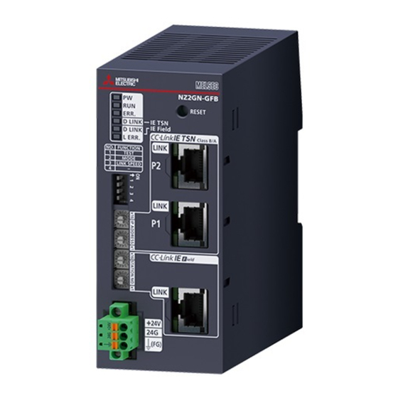
Page 15: Chapter 1 Part Names
This switch sets the functions of the NZ2GN-GFB. ( Page 29 Function setting switch setting) CC-Link IE TSN IP address Sets the IP address (fourth octet) of CC-Link IE TSN. ( Page 26 Settings for CC-Link IE TSN IP address setting setting switch... - Page 16 Normal completion Abnormal completion *1 If the CC-Link IE TSN master station becomes absent during network initialization, the D LINK LED may flash continuously. *2 This only applies when the NZ2GN-GFB is used as the CC-Link IE Field Network local station.
-
Page 17: Chapter 2 Specifications
SPECIFICATIONS General Specifications The following table lists the general specifications. Item Specifications Operating ambient 0 to 55 temperature Storage ambient -25 to 75 temperature Operating ambient 5 to 95%RH, non-condensing humidity Storage ambient humidity Vibration resistance Compliant with IEC Frequency Constant Half amplitude... -
Page 18: Performance Specifications
*1 For details on time-managed polling, refer to the following. User's manual for the master station used *2 Ring topology cannot be used when the CC-Link IE TSN Class is CC-Link IE TSN Class A. *3 256 points (512 bytes) for high-speed mode. -
Page 19: Ethernet Communication Specifications
Ethernet Communication Specifications The following table shows the Ethernet communication specifications for the NZ2GN-GFB. CC-Link IE TSN Item Description Data transmission speed 1Gbps or 100Mbps Communication mode 1000BASE-T Full-duplex 100BASE-TX Interface RJ45 connector (AUTO MDI/MDI-X) Maximum frame size 1518 bytes... -
Page 20: Function List
RX, RY, RWr, and I/O maintenance settings Sets whether to hold or clear the data to be transmitted from CC-Link IE TSN to CC-Link IE Page 73 I/O maintenance Field Network or vice versa, when an error occurs in the NZ2GN-GFB or the CC-Link IE TSN settings master station. - Page 21 CC-Link IE TSN Class Sets the CC-Link IE TSN Class of the NZ2GN-GFB as CC-Link IE TSN Class A or B of CC-Link Page 93 CC-Link IE TSN setting function IE TSN Protocol version 2.0.
-
Page 22: Chapter 3 Procedures Before Operation
This chapter describes the procedures before operation. Setting switches Set the following switches. Page 26 Settings for CC-Link IE TSN IP address setting switch Page 28 Settings for CC-Link IE Field Network station number setting switch Page 29 Function setting switch setting Mounting the module Mount the NZ2GN-GFB on a DIN rail. - Page 23 MEMO 3 PROCEDURES BEFORE OPERATION...
-
Page 24: Chapter 4 System Configuration
When the NZ2GN-GFB is used as the CC-Link IE Field Network local station When the NZ2GN-GFB is used as the CC-Link IE Field Network local station, communication can be made between personal computers of the CC-Link IE TSN master station and the CC-Link IE Field Network master station. CC-Link IE Field Network... -
Page 25: Network Topology
A ring topology can be used only when the CC-Link IE TSN Class setting of the master station is B. If a ring topology is used with an NZ2GN-GFB module that has CC-Link IE TSN Class A, data link cannot be performed. -
Page 26: Applicable Systems
Applicable Systems Applicable master station When using the NZ2GN-GFB, use the following products as a master station. ■CC-Link IE TSN Use the following products as a master station for CC-Link IE TSN. Model Name Firmware version RJ71GN11-T2 No restriction RD78G64, RD78G32, RD78G16, RD78G8, RD78G4 RD78GHV, RD78GHW "05"... - Page 27 The profile is a setting file that stores information required for the start-up, operation, and maintenance of devices supporting the CC-Link family. A module is added to "Module List" of the "CC-Link IE TSN Configuration" window by profile registration to the engineering tool of the master station.
-
Page 28: Chapter 5 Installation And Wiring
Settings for CC-Link IE TSN IP address setting switch Set the fourth octet of the CC-Link IE TSN IP address using the CC-Link IE TSN IP address setting switches on the front of the NZ2GN-GFB. The setting of CC-Link IE TSN IP address setting switch is enabled when the NZ2GN-GFB is powered on, so set this function when the module is powered off. - Page 29 When the value from 1 to 254 is set, the result is as follows. • The first to third octets of the IP address: The first to third octets from the IP address of the CC-Link IE TSN master station are used for operation.
-
Page 30: Settings For Cc-Link Ie Field Network Station Number Setting Switch
Set the station number using the CC-Link IE Field Network station number setting switch x1 and x16 (hexadecimal). The setting method is the same as for the CC-Link IE TSN IP address setting switch. ( Page 26 Setting method) Setting range ■When the NZ2GN-GFB is used as the CC-Link IE Field Network master station... -
Page 31: Function Setting Switch Setting
Turn it on when performing unit tests. ( Page 144 Unit Test) Function setting switch 2 MODE CC-Link IE TSN Class setting function Sets CC-Link IE TSN Class. ( Page 93 CC-Link IE TSN Class setting function) Function setting switch 3 LINK SPEED Communication speed setting Set the communication speed. -
Page 32: Installation Environment And Installation Position
Installation Environment and Installation Position Installation environment Installation location Do not install the NZ2GN-GFB in the following environment: • Ambient temperature is outside the range from 0 to 55; • Ambient humidity is outside the range from 5 to 95% RH; •... -
Page 33: Installation Position
(For the front direction, provide a clearance of 60mm or more (2).) When installing two or more NZ2GN-GFB and CC-Link IE TSN remote modules next to each other, they can be installed in contact with each other. -
Page 34: Mounting Direction
Mounting direction Use a DIN rail to install the NZ2GN-GFB. The NZ2GN-GFB can only be installed from the front. (1) DIN rail Do not place the module in the directions shown below. (1) Downward installation (2) Horizontal installation (3) Horizontal installation (upside down) (4) Upward installation 5 INSTALLATION AND WIRING 5.2 Installation Environment and Installation Position... -
Page 35: Installation
Installation Mounting a module on a DIN rail Installation procedure Hang the fixed upper tabs at the bottom of the NZ2GN- GFB on a DIN rail. Push in the DIN rail hooks of the NZ2GN-GFB until they click. Do not slide modules from the edge of the DIN rail when mounting them. It may damage the NZ2GN-GFB. 5 INSTALLATION AND WIRING 5.3 Installation... - Page 36 Removal procedure Remove the NZ2GN-GFB from the DIN rail by reversing the above procedure. While pushing down the DIN rail hook with a flathead screwdriver, remove the NZ2GN-GFB from the DIN rail by pulling its lower part toward you. Applicable DIN rail models Use the following DIN rails that are compliant with JIS C 2812 and IEC 60715.
-
Page 37: Wiring Of Terminal Block For Module Power Supply And Fg
Wiring of Terminal Block for Module Power Supply and FG Tightening torque Tighten the terminal block mounting screws within the following specified torque range. Tightening the screws too much may damage the NZ2GN-GFB case. Screws tightened Tightening torque range Terminal block mounting screw (M2.5 screw) 0.2 to 0.3Nm Wire to be used The following table describes the wire to be connected to the terminal block for module power supply and FG. - Page 38 Installing and removing the terminal block To remove the terminal block, loosen the terminal block mounting screws with a flathead screwdriver. To install the terminal block, tighten the terminal block mounting screw with a flathead screwdriver. Failure to secure the terminal block may cause drop, short circuit, or malfunction. 5 INSTALLATION AND WIRING 5.4 Wiring of Terminal Block for Module Power Supply and FG...
- Page 39 Connecting and disconnecting the cable To connect the cable, push in the open/close button with a flathead screwdriver, insert the wire into the wire insertion opening, and remove the flathead screwdriver. When using a bar solderless terminal, insert a wire with the bar solderless terminal into the wire insertion opening and push the wire.
- Page 40 Precautions • When using a wire (stranded wire), strip off 10mm of the sheath from the wire end. • When using a bar solderless terminal, follow the strip length of wire in the specifications of the bar solderless terminal. To attach a bar solderless terminal to a wire, use a crimping tool.
-
Page 41: Wiring Of Ethernet Cable
However, if link-up processing is repeated due to a condition of a device on the line, the longer time may be required. *2 When the communication speed of CC-Link IE TSN is set to 100Mbps and a device that can transmit at a speed of 100Mbps is connected to P1 and P2 of the NZ2GN-GFB, enable auto-negotiation of the device. - Page 42 ■CC-Link IE Field Network side Power off the power supplies of the NZ2GN-GFB and the external device. Push the Ethernet cable connector into the NZ2GN-GFB until it clicks. Pay attention to the direction of the connector. Power on the power supplies of the NZ2GN-GFB and the external device. Check whether LINK LED is on.
-
Page 43: Precautions
Precautions Precautions when connecting a media converter The following indicates the criteria under which a media converter can be used in CC-Link IE Field Network. Inquire with the manufacturer of the media converter to determine if it meets the usage criteria. •... -
Page 44: Chapter 6 Parameter Settings
Network Topology "Line/Star" or "Ring" can be set. To set "Ring", make sure that the CC-Link IE TSN Class of the NZ2GN-GFB is B. If a module that has CC-Link IE TSN Class A is connected, data link cannot be performed. - Page 45 The following shows the NZ2GN-GFB items set in network configuration settings. ■Setting procedure Open the "CC-Link IE TSN Configuration" window from the parameter of the CC-Link IE TSN master station. [Navigation window] [Parameter] [Module Information] Model name [Basic Settings] [Network Configuration Settings] Select the NZ2GN-GFB in "Module List"...
- Page 46 CC-Link IE Field Network of the NZ2GN-GFB. *6 If a different CC-Link IE TSN Class value than the one set using function setting switch 2 is used, the event code of 00C81 is registered with the event history of the CC-Link IE TSN master station, and the NZ2GN-GFB does not perform data link.
-
Page 47: Parameter Settings For Cc-Link Ie Field Network
The following shows the NZ2GN-GFB items set in network configuration settings. ■Setting procedure Open the "CC-Link IE TSN Configuration" window from the parameter of CC-Link IE Field Network master station. [Navigation window] [Parameter] [Module Information] Model name [Basic Settings] [Network Configuration Settings] Select a general local station in "Module List"... - Page 48 1D01H is registered with the event history of the CC-Link IE Field Network master station. *2 If the CC-Link IE TSN Class setting of the NZ2GN-GFB is set to A, set the values so that the total number of "RX/RY Setting" and "RWw/ RWr Setting"...
-
Page 49: Module Parameter Setting
Module Parameter Setting Set the module parameters of the NZ2GN-GFB from the "CC-Link IE TSN Configuration" window of the engineering tool. The following methods are available for to set the parameters of the NZ2GN-GFB. • Parameter Automatic Setting ( Page 57 Parameter automatic setting) •... - Page 50 Parameter A Parameter A • Parameter A: Parameter set using parameter automatic setting. The CC-Link IE TSN master station retains this parameter and sends it when the NZ2GN- GFB performs data link. • Parameter B: Parameter set using device station parameter processing.
- Page 51 *1 If a parameter is not set, the module will operate using the default value. *2 If a different value from the CC-Link IE TSN master station setting is set, it may not be possible to perform transient transmission. 6 PARAMETER SETTINGS...
- Page 52 (Default: 2) may not be successful. If the CC-Link IE TSN network No. and the setting value overlap, an error (error code: 0290H) occurs and all parameters are not saved in the non-volatile memory of the NZ2GN-GFB. Set it again after correcting the value.
- Page 53 NZ2GN-GFB. Set it again after correcting the value. ( Page 16 Performance Specifications) *6 If the CC-Link IE TSN Class setting is set to A, set the values so that the total number of "RX/RY points" and "RWw/RWr points" does not exceed 2048 bytes.
- Page 54 NZ2GN-GFB. Set it again after correcting the value. IP address (1st Sets the IP address of the other station on CC-Link IE TSN that forms the path 0 to 223 octet) when communicating between different networks.
- Page 55 *8 If a parameter is not set, the module will operate using the default value. *9 To set CC-Link IE TSN station No. <-> IP address conversion setting for 17 items or more, use the remote buffer memory and set the parameter using a program.
- Page 56 Dynamic routing • 0: Disable • 1: Enable (Default: 1: Enable) Valid number of "CC-Link IE TSN station No. <-> IP address conversion setting" 0 to 16 (Default: 0) Valid number of routing setting 0 to 16 (Default: 0) CC-Link IE TSN station No. <-> IP Station No.
- Page 57 (1) Send to station No.2 of CC-Link IE TSN. (2) Send to the NZ2GN-GFB. (3) CC-Link IE TSN station No. <-> IP address conversion setting does not need to be set because communication is not done between different networks with the NZ2GN-GFB as a relay station.
- Page 58 • Reset using the reset switch (Page 13 PART NAMES) • Reset using "Remote reset request" (Page 56 Resetting using "Remote reset request") • Remote reset from CC-Link IE TSN diagnostics (Page 119 Remote reset) ■Resetting using "Remote reset request"...
-
Page 59: Parameter Automatic Setting
Those parameters are read from the CC-Link IE TSN master station and set automatically when the NZ2GN-GFB performs data link. The parameters automatically set from the CC-Link IE TSN master station are also stored in the non-volatile memory in the NZ2GN-GFB. - Page 60 Set the network parameters. For details on the network parameters, refer to the following. User's manual for the master station used Select the "Parameter Automatic Setting" checkbox of the network parameters. When the settings of the parameter automatic setting are not configured yet, the font of the [Detail Setting] button is blue.
- Page 61 Check that the font of the [Detail Setting] button has changed to black for the NZ2GN-GFB with changed settings. Click the [Close with Reflecting the Setting] button to close the "CC-Link IE TSN Configuration" window. When the parameter setting has been completed, click the [Apply] button.
- Page 62 The module parameters will be written to the CPU module by performing [Write to PLC] operation, but they will not be written to the NZ2GN-GFB. Set the CPU module of the CC-Link IE TSN master station to RUN, and check that the D LINK LED (CC-Link IE TSN) of the NZ2GN-GFB is turned on.
- Page 63 • If the NZ2GN-GFB is not turned off and on or reset, the system runs using the old parameters. • If the parameter automatic setting is completed with an error, data link cannot be performed on CC-Link IE TSN. Device station parameter automatic setting interruption (event code: 00C40) is stored in the event history of the CC-Link IE TSN master station.
-
Page 64: Device Station Parameter Processing
When "Station-specific mode settings" have been changed, write the set parameters to the CPU module of the CC-Link IE TSN master station and reset the CPU module of the CC-Link IE TSN master station, or turn off and on the power supply of the programmable controller. - Page 65 Open the "Parameter of Device Station" window. When the "Parameter of Device station" window appears, the "Station-specific mode setting" window to confirm the settings appears. If it is not the CC-Link IE Field Network station type that you want to set in the NZ2GN-GFB, stop the process and look at "Station-specific mode setting"...
- Page 66 Double-click the item to change the setting, and input the setting value. To save the parameter information in a CSV file, click the [Export] button. To read the parameter information from a CSV file, click the [Import] button. Set all the items for the parameter. If any item is left blank, the parameter cannot be written to the NZ2GN- GFB.
- Page 67 Precautions • If the NZ2GN-GFB is not turned off and on or reset, the system runs using the old parameters. • Invalid parameters are not saved in the non-volatile memory. Check the event history after writing parameters. If "Parameter read" is performed after writing an invalid parameter, the invalid parameter is read instead of the parameter saved in the non-volatile memory.
-
Page 68: Parameter Settings For Cc-Link Ie Field Network Device Station
After setting the CC-Link IE TSN parameters, write the set parameters to the CPU module of the CC-Link IE TSN master station and reset the CPU module of the CC-Link IE TSN master station, or turn off and on the power supply of the programmable controller. - Page 69 Click the [Detect Now] button to read the connected CC-Link IE Field Network device stations. For details on automatic detection of CC-Link IE Field Network device stations, refer to the following. iQ Sensor Solution Reference Manual Setting item ■Parameter Processing of Device Station Select the device station.
-
Page 70: Chapter 7 Functions
FUNCTIONS Cyclic Transmission Communications using RX, RY, RWr, and RWw The NZ2GN-GFB can periodically exchange data among stations on CC-Link IE TSN and CC-Link IE Field Network by transferring a link device (RX, RY, RWr, or RWw). 7 FUNCTIONS 7.1 Cyclic Transmission... - Page 71 When the NZ2GN-GFB is used as the CC-Link IE Field Network master station, cyclic transmission can be performed between the CC-Link IE TSN master station and CC-Link IE Field Network device stations using a link device (RX, RY, RWr, or RWw).
- Page 72 The first 32 remote register (RWr/RWw) points assigned to the NZ2GN-GFB by the CC-Link IE TSN master station is used by the system, so they cannot be used for data exchange with CC-Link IE Field Network device stations. 7 FUNCTIONS...
- Page 73 When the NZ2GN-GFB is used as the CC-Link IE Field Network local station, cyclic transmission can be performed between the CC-Link IE TSN master station and CC-Link IE Field Network master station using a link device (RX, RY, RWr, or RWw).
- Page 74 • The cyclic data of each station other than the CC-Link IE Field Network master station cannot be sent on the CC-Link IE TSN line. To receive the cyclic data of each station other than the CC-Link IE Field Network master station in the CC-Link IE TSN master station, store the cyclic data of each station on CC-Link IE Field Network in the NZ2GN-GFB range assignment from the CC-Link IE Field Network master station.
-
Page 75: I/O Maintenance Settings
I/O maintenance settings This function sets whether to hold or clear the data to be transmitted from CC-Link IE TSN to CC-Link IE Field Network or vice versa, when an error occurs in the NZ2GN-GFB or the CC-Link IE TSN master station. - Page 76 ■When the NZ2GN-GFB is used as the CC-Link IE Field Network master station When a data link error occurs in CC-Link IE TSN, the data transmitted from the CC-Link IE TSN master station to CC-Link IE Field Network device stations (RY) is held or cleared according to the configured settings.
- Page 77 This setting can only be set when the NZ2GN-GFB is used as the CC-Link IE Field Network master station. When the CPU module of the CC-Link IE TSN master station is changed from RUN to STOP, the transmitted data in the NZ2GN-GFB (RY) is held or cleared depending on the configured settings.
- Page 78 Network is stopped intentionally without an error occurring, the input status is retained. • When "Output hold/clear setting during CC-Link IE TSN master station CPU STOP" is set to "0: Clear" and the CPU module of the CC-Link IE TSN master station is stopped, forced output to CC-Link IE Field Network device stations using an engineering tool cannot be performed.
-
Page 79: Cyclic Transmission Stop And Restart
Cyclic transmissions can be stopped and restarted using the following methods. Item Reference Page 121 CC-Link IE Field Network diagnostics "Link Start/Stop" of "CC-Link IE TSN/CC-Link IE Field Diagnostics" Page 223 Details of remote buffer memory (Link special relay (SB) area of CC-Link IE Field Remote buffer memory Network) Page 241 Details of remote buffer memory (Link special register (SW) area of CC-Link IE Field... -
Page 80: Transient Transmission
MELSEC iQ-R Programming Manual (Module Dedicated Instructions) User's manual for the master station used Dedicated instructions for the NZ2GN-GFB The following table lists the dedicated instructions that can be executed in the NZ2GN-GFB from the CC-Link IE TSN master station. CPU module... - Page 81 Do not execute multiple dedicated instructions at the same time for a single NZ2GN-GFB. If multiple dedicated instructions are executed at the same time, the NZ2GN-GFB may not be able to receive the dedicated instructions, and the dedicated instructions may time out. 7 FUNCTIONS 7.2 Transient Transmission...
- Page 82 If a dedicated instruction can be executed in the station of another network, the NZ2GN-GFB can be used as a relay station to execute the instruction. For the applicable dedicated instructions, refer to the user's manual for the master station used. CPU module CC-Link IE Field CC-Link IE TSN CPU module Network Ò master station...
-
Page 83: Transient Transmission With Other Stations Using Remote Buffer Memory
Transient transmission can be performed with another station that is connected to CC-Link IE Field Network by reading/writing the NZ2GN-GFB remote buffer memory from the program of the CPU module of the CC-Link IE TSN master station when the NZ2GN-GFB is used as the CC-Link IE Field Network master station. - Page 84 Operation This section describes the operations for normal completion and completion with an error using REMFR as an example. ■When the process is completed successfully Setting 'Setting data' (16002H to 1601FH) Setting value B value A 'Handshake flag' (16000H) 0 (completed 0 (completed 'Completion status' (16001H) 0 (initial value)
- Page 85 ■When the send processing is completed with an error (error detected) Setting 'Setting data' (16002H to 1601FH) Setting value B value A 'Handshake flag' (16000H) 'Completion status' (16001H) 0 (initial value) Error code 0 (initial value) 'Read data storage buffer' (16220H to 163FFH) Operation starts An error is...
- Page 86 ■When the process is completed with an error (abnormal response from the target station) Setting 'Setting data' (16002H to 1601FH) Setting value B value A 'Handshake flag' (16000H) Error code 0 (initial value) 'Completion status' (16001H) 0 (initial value) 'Read data storage buffer' (16220H to 163FFH) Operation starts with An abnormal response is...
-
Page 87: Communications Using The Slmp
• Port: 45239 • Code: Binary code How to communicate Use the SLMPSND instruction to send SLMP commands to the NZ2GN-GFB from the CPU module of the CC-Link IE TSN of the master station. For the SLMPSND instruction, refer to the following. -
Page 88: Communications Using The Engineering Tool
Communications using the engineering tool CC-Link IE TSN and CC-Link IE Field Network stations can be accessed seamlessly with the NZ2GN-GFB as a relay using an engineering tool. For the access range, refer to the user's manual for the master station used. - Page 89 Communication test This test checks if transient transmission data can be properly routed from the own station to the communication target. For details, refer to the user's manual for the CC-Link IE TSN master station used. 7 FUNCTIONS 7.2 Transient Transmission...
-
Page 90: Ras
RAS stands for Reliability, Availability, and Serviceability. This function improves overall usability of automated equipment. Module power supply voltage drop detection Detects a voltage drop of the module power supply. This function makes troubleshooting easy when the voltage of power supplied to the NZ2GN-GFB drops or when poor connection in the wiring occurs. -
Page 91: Device Station Disconnection
• The actual CC-Link IE Field Network configuration and the network map • The cable connected to the switching hub is unplugged and of the "CC-Link IE TSN/CC-Link IE Field Diagnostics" window may not unplugged, and the connection destination of CC-Link IE Field match. -
Page 92: Master Station Duplication Detection
Master station duplication detection If one network has multiple CC-Link IE Field Network master stations, an overlap error is detected. After resolving the cause of error for the affected station, reset or turn off and on the module to restore the system. Simultaneously turning off and on the power When multiple master stations are simultaneously powered off and on or connected, an error is detected in all master stations and cyclic transmission and transient transmission cannot be performed in all stations. -
Page 93: Station Number Duplication Detection
Station number duplication detection If one network has CC-Link IE Field Network device stations with the same station number, a duplication error is detected. After resolving the cause of error for the affected station, reset or turn off and on the module to restore the system. If the network number is different, station number duplication is not detected. -
Page 94: Others
Page 179 Communication speed setting status (RWr2.b8) Precautions • Depending on the communication speed, the communication cycle range of the CC-Link IE TSN master station that can be set varies. For details, refer to the following. Page 42 Communication Period Interval Setting •... -
Page 95: Cc-Link Ie Tsn Class Setting Function
CC-Link IE TSN Class setting function This function sets the CC-Link IE TSN Class of the NZ2GN-GFB as CC-Link IE TSN Class A or B of CC-Link IE TSN Protocol version 2.0. For differences between system configurations that can be connected depending on the CC-Link IE TSN Class, refer to the following. - Page 96 Set the CC-Link IE TSN Class using the engineering tool. For details, refer to the following. Page 43 Network Configuration Settings Checking setting status The status set using the setting function of the CC-Link IE TSN Class can be checked with remote registers or an engineering tool. ■Checking with remote registers The status can be checked with 'CC-Link IE TSN Class setting status' (RWr2.b11) of the remote register.
- Page 97 CC-Link IE TSN Class to B. • When CC-Link IE TSN Class A is set for the CC-Link IE TSN Class, set the total points for the link device used by the NZ2GN-GFB in CC-Link IE Field Network to meet the following criteria.
-
Page 98: Reserved Station Setting
Reserved station setting This function sets a CC-Link IE Field Network device station as a reserved station when the NZ2GN-GFB is used as the CC- Link IE Field Network master station. Reserved stations are included as stations in the network for future extension and set in the parameters. These stations are not regarded as faulty stations even though they are not connected to an actual network. -
Page 99: Error Invalid Station Setting
Error invalid station setting This function prevents a CC-Link IE Field Network device station from being detected as a faulty station when the NZ2GN- GFB is used as the CC-Link IE Field Network master station. It is also set when a device station is to be replaced during communication. Setting method When setting the CC-Link IE Field Network device station as an error invalid station, set the NZ2GN-GFB module parameter of "Reserved/error invalid station"... -
Page 100: Chapter 8 Programming
When the NZ2GN-GFB is used as the CC-Link IE Field Network master station For a cyclic transmission program on CC-Link IE TSN, configure an interlock with the following link special relay (SB), link special register (SW), and the NZ2GN-GFB remote registers. - Page 101 When the NZ2GN-GFB is used as the CC-Link IE Field Network local station For a cyclic transmission program on CC-Link IE TSN, configure an interlock with the following link special relay (SB), link special register (SW), and the NZ2GN-GFB remote registers.
-
Page 102: Transient Transmission Program
(SB), link special register (SW), and the NZ2GN-GFB remote registers. • Own station data link status (CC-Link IE TSN master station) (SB0049) • Data link status of each station (CC-Link IE TSN master station) (SW00B0 to SW00B7) • 'CC-Link IE Field Network operating status' (RWr6 to RWr7) •... -
Page 103: Program Examples
System configuration (1) CC-Link IE TSN master station (base unit: R35B, power supply module: R62P, CPU module: R04CPU, master/local module: RJ71GN11-T2 (start I/O number: 0000H to 001FH)) (2) NZ2GN-GFB (CC-Link IE TSN: station No.1, CC-Link IE Field Network: No.0 (master station)) (3) NZ2GF2B-60AD4 (CC-Link IE Field Network remote device station (station No.1)) - Page 104 Parameter settings Connect the engineering tool to the CPU module on the CC-Link IE TSN master station and set the parameters. Set the CPU module as follows. [Project] [New] Set "Link Direct Device Setting" in "CPU Parameter" to "Extended Mode (iQ-R Series Mode)".
- Page 105 Click the [Close with Reflecting the Setting] button to close the "CC-Link IE TSN Configuration" window. Click the [Apply] button. Write the set parameters to the CPU module on the CC-Link IE TSN master station. Then, reset the CPU module or power off and on the system.
- Page 106 Display the CC-Link IE TSN configuration window and select the "Parameter Automatic Setting" checkbox of the NZ2GN-GFB. Double-click [Detail Setting] beside the "Parameter Automatic Setting" checkbox to display the "Parameter of Device Station" window. Set "Method selection" to "Parameter write".
- Page 107 Power off and on the NZ2GN-GFB or reset it. Set the CPU module of the CC-Link IE TSN master station to RUN, and check that the D LINK LED (CC-Link IE TSN) and D LINK LED (CC-Link IE Field) of the NZ2GN-GFB is turned on.
- Page 108 Program example (1) The following program is for communicating between the CPU module of CC-Link IE TSN master station and the NZ2GN- GFB. ■Devices to be used Device Description SB49 Own station data link error status of CC-Link IE TSN master station SW0B0.0...
- Page 109 ( Page 81 Transient transmission with other stations using remote buffer memory) The following program is to read the remote buffer memory of the CC-Link IE Field Network remote device station from the CPU module of the CC-Link IE TSN master station using the REMFR instruction. ■Devices to be used...
- Page 110 Specifies the setting data (CC-Link IE Field Network remote device station (station No.1)) to be used by dedicated instructions. (70) Reads the handshake flag by turning on M1. (133) Writes the setting data after instruction specification. (172) Updates the handshake flag. (idle send request) (223) Reads the handshake flag and turns on M6 if the flag is Reception request or Transmission completed with an error.
-
Page 111: When The Nz2Gn-Gfb Is Used As The Cc-Link Ie Field Network Local Station
System configuration (1) CC-Link IE TSN master station (base unit: R35B, power supply module: R62P, CPU module: R04CPU, master/local module: RJ71GN11-T2 (start I/O number: 0000H to 001FH)) (2) NZ2GN-GFB (CC-Link IE TSN: station No.1, CC-Link IE Field Network: station No.1) - Page 112 Parameter settings ■Setting parameters on the CC-Link IE TSN side Connect the engineering tool to the CPU module on the CC-Link IE TSN master station and set the parameters. Set the CPU module as follows. [Project] [New] Set "Link Direct Device Setting" in "CPU Parameter" to "Extended Mode (iQ-R Series Mode)".
- Page 113 Click the [Close with Reflecting the Setting] button to close the "CC-Link IE TSN Configuration" window. Click the [Apply] button. Write the set parameters to the CPU module on the CC-Link IE TSN master station. Then, reset the CPU module or power off and on the system.
- Page 114 Click the [Close with Reflecting the Setting] button to close the "CC-Link IE TSN Configuration" window. Power off and on the NZ2GN-GFB or reset it. Set the CPU module of the CC-Link IE TSN master station to RUN, and check that the D LINK LED (CC-Link IE TSN) of the NZ2GN-GFB is turned on.
- Page 115 ■Settings parameters on the CC-Link IE Field Network side Connect the engineering tool to the CPU module on the CC-Link IE Field Network master station and set the parameters. Set the CPU module as follows. [Project] [New] Set the RJ71GF11-T2 as follows. [Navigation window] ...
- Page 116 Set the refresh settings as follows. [Navigation window] [Parameter] [Module Information] [RJ71GF11-T2] [Basic Settings] [Refresh Settings] [Detailed Setting] Display the CC-Link IE Field configuration window and register a general local station. [Navigation window] [Parameter] [Module Information] [RJ71GF11-T2] [Basic Settings] [Network Configuration Settings] ...
- Page 117 Own station data link error status of CC-Link IE TSN master station SW0B0.0 Data link status of each station on CC-Link IE TSN (station No.1 (NZ2GN-GFB)) Communication ready flag (CC-Link IE TSN station No.1) Nesting (CC-Link IE TSN station No.1) W107.0...
- Page 118 Communication ready flag (CC-Link IE Field Network station No.1) Nesting (CC-Link IE Field Network station No.1) Start device of data that is sent to CC-Link IE TSN master station W200 Device to which RWw0 of CC-Link IE TSN master station is assigned...
-
Page 119: Chapter 9 Maintenance And Inspection
MAINTENANCE AND INSPECTION The NZ2GN-GFB has no special item to be inspected. However, to maintain the best condition of the system, perform an inspection in accordance with the inspection items described in the following manual based on the system configuration of the master station used. - Page 120 MEMO 9 MAINTENANCE AND INSPECTION...
-
Page 121: Chapter 10 Troubleshooting
Status monitoring, operation tests, or other diagnostics are performed for CC-Link IE TSN and CC-Link IE Field Network. CC-Link IE TSN diagnostics CC-Link IE TSN can be diagnosed using the engineering tool connected to the CPU module of the CC-Link IE TSN master station and local station. - Page 122 Information on the NZ2GN-GFB, such as the production information, firmware version, and module inherent information, can be checked by clicking the [Station Information List] button in the "CC-Link IE TSN/CC-Link IE Field Diagnostics" window. For items displayed in the "Station Information List" window, refer to the following.
-
Page 123: Cc-Link Ie Field Network Diagnostics
CC-Link IE Field Network diagnostics CC-Link IE Field Network can be diagnosed using the engineering tool connected to the CPU module of the CC-Link IE TSN master station and local station. [Diagnostics] [CC-Link IE TSN/CC-Link IE Field Diagnostics] Select the NZ2GN-GFB Right-click [CC-Link IE... - Page 124 *1 This item cannot be used when a setting other than "No Specification" is specified in "Other Station Setting" on the "Specify Connection Destination Connection" window. *2 Remote reset of the NZ2GN-GFB cannot be performed by remote operation. Reset remotely from CC-Link IE TSN diagnostics. The following functions cannot be used in the CC-Link IE Field Network diagnostics executed with these steps.
- Page 125 Range for performing diagnostics CC-Link IE Field Network diagnostics of the NZ2GN-GFB can be started from CC-Link IE TSN diagnostics only when all of the following conditions are met. • On the communication route from the station directly connected to the engineering tool to the CC-Link IE Field Network to which the NZ2GN-GFB is connected, the NZ2GN-GFB is a relay sending station on the CC-Link IE Field Network.
- Page 126 • MELSECNET/H • Multidrop connection with a serial communication module • Interface board for a personal computer • GOT (when the transparent function is used) • MELSEC-Q/L series network module 10 TROUBLESHOOTING 10.1 CC-Link IE TSN/CC-Link IE Field Diagnostics...
- Page 127 Set output data if needed. [Legend] button Displays the meaning of icons displayed in the CC-Link IE Field Network diagnostics. St. Info Displays the station type. 10 TROUBLESHOOTING 10.1 CC-Link IE TSN/CC-Link IE Field Diagnostics...
- Page 128 *1 When the NZ2GN-GFB is used as the CC-Link IE Field Network local station, refer to the user's manual for the CC-Link IE Field Network master station used. *2 The network map match status can be checked using 'Network configuration mismatch occurrence status' (2009H.b8). ( Page 230 Network configuration mismatch occurrence status (2009H.b8)) 10 TROUBLESHOOTING 10.1 CC-Link IE TSN/CC-Link IE Field Diagnostics...
- Page 129 Two stations are connected through a switching hub. Branches are not displayed in the network map. No.0 No.3 Switching hubs are in cascade connection. Only one branch is displayed. No.0 No.1 No.2 No.3 10 TROUBLESHOOTING 10.1 CC-Link IE TSN/CC-Link IE Field Diagnostics...
- Page 130 Displays the module LED status and CC-Link IE Field Network communication connector communication status. ( Page 13 PART NAMES) Displays the cable status of the CC-Link IE Field Network communication connector. 10 TROUBLESHOOTING 10.1 CC-Link IE TSN/CC-Link IE Field Diagnostics...
- Page 131 • Station where link was stopped by a command from another station • Station where link was stopped by the remote buffer memory of the NZ2GN-GFB *1 Selecting "Forced Link Start" will start the link. 10 TROUBLESHOOTING 10.1 CC-Link IE TSN/CC-Link IE Field Diagnostics...
- Page 132 Diagnostics" window, select the icon of the station to be reserved again. Right-click the selected icon, and select "Reserved Station Disabled (Activated) for the Selected Station". The text background turns light blue. The slave station is reserved again. 10 TROUBLESHOOTING 10.1 CC-Link IE TSN/CC-Link IE Field Diagnostics...
- Page 133 • Information on 'Reserved station setting status' (30C0H to 30C7H) and 'Reserved station cancel setting status' (3180H to 3187H) The difference can be corrected by the following procedure. Reconnect the disconnected station. Disable the reserved station setting, and enable the reserved station setting again. 10 TROUBLESHOOTING 10.1 CC-Link IE TSN/CC-Link IE Field Diagnostics...
- Page 134 ■Checking the station number of a reserved station The station number of a reserved station can be checked in the "Reserved Station Function Enable" window. 10 TROUBLESHOOTING 10.1 CC-Link IE TSN/CC-Link IE Field Diagnostics...
- Page 135 Right-click the selected icon, and select "Ignoring Station Errors Setting for the Selected Station". The text background turns white. The temporary error invalid station setting is canceled. 10 TROUBLESHOOTING 10.1 CC-Link IE TSN/CC-Link IE Field Diagnostics...
- Page 136 Click the [OK] button to cancel temporary error invalid station setting. ■Stations which cannot be set as a temporary error invalid station The temporary error invalid station setting is not available for temporarily canceled reserved stations. 10 TROUBLESHOOTING 10.1 CC-Link IE TSN/CC-Link IE Field Diagnostics...
- Page 137 Configure the temporary error invalid station setting, and cancel the setting. ■Checking the station number of an error invalid station The station number of an error invalid station can be checked in the "Enable/Disable Ignore Station Errors" window. 10 TROUBLESHOOTING 10.1 CC-Link IE TSN/CC-Link IE Field Diagnostics...
- Page 138 This function executes remote operations (such as RUN, STOP, and RESET operations) to the station selected on the "CC- Link IE Field Diagnostics" window, from the engineering tool. The displayed window varies depending on the station selected. For details, refer to the manual for the module used. 10 TROUBLESHOOTING 10.1 CC-Link IE TSN/CC-Link IE Field Diagnostics...
-
Page 139: Checking The Leds
10.2 Checking the LEDs This section describes how to troubleshoot the system by the LEDs. Determining the module error status An error status can be determined by the on/off status of RUN LED and ERR. LED as follows. RUN LED ERR. - Page 140 Disconnect any device that does not support CC-Link IE TSN. between the CC-Link IE TSN master station and the NZ2GN- For a device that can be set to operate on CC-Link IE TSN, make sure that it is operating as GFB? CC-Link IE TSN.
- Page 141 Is the system configured with a ring topology? When the CC-Link IE TSN Class of the NZ2GN-GFB is set to A (function setting switch 2 is on), change the class to B (turn off function setting switch 2), or set the system configuration to a line topology, a star topology, or mixture of line topology and star topology.
- Page 142 Check item Action Is the network overloaded? Reduce the load on the network using the steps below. • If a broadcast storm has occurred, eliminate the cause. • The NZ2GN-GFB may not be able to send packets because it intermittently relays packets sent from an Ethernet device to other stations.
- Page 143 When D LINK LED (CC-Link IE Field) is off or flashing When the D LINK LED (CC-Link IE Field) turns off, check the following. Check item Action When the NZ2GN-GFB is Are Ethernet cables used compliant with Replace the cable with an Ethernet cable compliant with the relevant standard. ( used as the CC-Link IE the relevant standard? Page 39 Wiring product)
- Page 144 Check item Action When the NZ2GN-GFB is Are Ethernet cables used compliant with Replace the cable with an Ethernet cable compliant with the relevant standard. ( used as the CC-Link IE the relevant standard? Page 39 Wiring product) Field Network local station Is the segment length 100m or less? Change the segment length to 100m or less.
-
Page 145: Check With Remote Register And Remote Buffer Memory
10.3 Check with Remote Register and Remote Buffer Memory This section describes the troubleshooting of CC-Link IE Field Network using remote registers and remote buffer memory. Remote registers Check the following remote register items. ( Page 177 Details of remote registers) Check item Action Is 'Baton pass status of own station' (RWr6.b0) on? -
Page 146: Unit Test
Run a unit test to check if there is any abnormality in the hardware of the NZ2GN-GFB. Power off the NZ2GN-GFB. Connect CC-Link IE TSN communication connectors P1 and P2 of the NZ2GN-GFB with an Ethernet cable. Turn on function setting switch 1 of the NZ2GN-GFB. -
Page 147: Troubleshooting By Symptom
If the actions described in this section do not solve the problem, perform a unit test to check for an error. ( Page 144 Unit Test) CC-Link IE TSN diagnostics and CC-Link IE Field Network diagnostics have failed When CC-Link IE TSN diagnostics and CC-Link IE Field Network diagnostics cannot be performed, check the following items. Check item Action... - Page 148 Set the network No. configured for the CC-Link IE TSN master station. as the CC-Link IE TSN master station network No.? Is "CC-Link IE TSN station No." in the module parameter the same as Set the station number configured using the network configuration settings of the CC- the station number configured using the network configuration Link IE TSN master station.
- Page 149 Is there any NZ2GN-GFB error shown in If an error is identified, perform a unit test. "Selected Station Communication Status ( Page 144 Unit Test) Monitor" of CC-Link IE TSN diagnostics? Is there any noise affecting the system? Check the wiring condition. CC-Link IE Field Network Is the L ERR.
-
Page 150: Checking Event Codes And Error Codes
• When the NZ2GN-GFB is used as the CC-Link IE Field Network master station, the time distributed from the CC-Link IE TSN master station is recorded as the occurrence time in the error and event history of the CC- Link IE Field Network device station. For operations before the time is distributed, refer to the user's manual for the CC-Link IE TSN master station used. - Page 151 To initialize the error and event history, click the [Delete Error/Event History] button. Checking the latest error code (RWr1) Check the latest error code with the remote registers of the CC-Link IE TSN master module. ■Procedure [Online] [Monitor] [Device/Buffer Memory Batch Monitor]...
-
Page 152: How To Clear An Error
How to clear an error using the command execution of device station This section describes the method to clear an error using the command execution of device station. Open the "CC-Link IE TSN Configuration" window. [Navigation window] [Parameter] [Module Information] Model name [Basic Settings] [Network Configuration Settings] Open the "Command Execution of Device Station"... -
Page 153: How To Clear An Event History
This section describes the method to clear an event history using the command execution of device station. Open the "CC-Link IE TSN Configuration" window. [Navigation window] [Parameter] [Module Information] Model name [Basic Settings] [Network Configuration Settings] Open the "Command Execution of Device Station"... -
Page 154: Error Code List
This sections describes the error codes of the NZ2GN-GFB. Error codes that can be checked using CC-Link IE TSN/CC-Link IE Field diagnostics The following table shows the error codes that can be checked with "Error history/event history" of CC-Link IE TSN/CC-Link IE Field diagnostics. - Page 155 Take any of the following actions. error Network allocation the NZ2GN-GFB in CC-Link IE Field • Set the CC-Link IE TSN Class setting to CC-Link IE point error (CC-Link IE Network exceeds 2,048 bytes. TSN Class B. TSN Class A) •...
- Page 156 • The parameters are not reflected in the module. (network No. "CC-Link IE Field Network No." in the • Change the "CC-Link IE TSN network No." and "CC- duplication error) module parameters are duplicated. Link IE Field Network No." so that they do not overlap, and set them again.
- Page 157 The "Station No." of the module • The parameters are not reflected in the module. Link IE TSN station No. parameter "CC-Link IE TSN station No. • Change the "Station No." so that it does not overlap, <-> IP address <->...
- Page 158 *1*2 D001H Minor error CC-Link IE TSN Network settings that cannot be • Check that the model name of the CC-Link IE TSN Communication setting handled by the NZ2GN-GFB are device station set in the network configuration settings error 2 received.
- Page 159 An IP address duplication is detected. Change the IP address so that no IP address duplication detection occurs in the access range of CC-Link IE TSN. After changing the settings, power off and on the NZ2GN- GFB or reset it.
- Page 160 The read/write request exceeds the largest address. • Correct the start address or the number of read/write points so that the request does not exceed the largest address and send the data to the CC-Link IE TSN- equipped module again.
- Page 161 • Correct the SLMP message to read/write data without the device memory set for access destination specified by the SLMP message. extension. • Specify the extension of the device memory only for the CC-Link IE TSN- equipped module mounted station and RCPU/QCPU/QnACPU via CC-Link IE Controller Network, MELSECNET/H, or MELSECNET/10.
- Page 162 Error code Error definition and causes Action D041H The number of communication stations is incorrect. • Check the network status using the CC-Link IE Field Network diagnostics of the engineering tool, and take action. • If the number of device stations per network is more than the maximum number of connectable stations, reduce it so that it does not exceed the maximum number.
- Page 163 Error code Error definition and causes Action D203H The read data or write address of the transient Correct the read data or write address at the transient request source, and retry the transmission is incorrect. operation. D204H The network number of transient transmission is •...
- Page 164 Error code Error definition and causes Action D21EH The target station number of transient transmission • A communication test cannot be executed on a relay sending station. Correct is incorrect. "Target Station" setting, and execute the communication test again. • Transient data of the application type that cannot be executed on the own station were received.
- Page 165 Error code Error definition and causes Action D23EH The information of the device station failed to be • Set the network configuration settings properly, write the parameters in the acquired. master station, and retry the operation. • If the error occurs again even after taking the above, please consult your local Mitsubishi representative.
- Page 166 Error code Error definition and causes Action D2ADH The data length in the transient transmission frame Correct the number of data (frame length) at the transient request source, and retry is incorrect. the operation. D2AEH The target station number in the transient •...
- Page 167 Error code Error definition and causes Action D842H • Routing information to the destination station • Correct the target network number at the transient request source, and retry the network number is not registered. operation. • In transient transmission, there are over seven •...
- Page 168 ■Error codes stored in 'Completion status' (16001H). The following table shows the error codes stored in 'Completion status' (16001H). Error code Error definition and causes Action 0001H A value that is out of range or cannot be set in the Refer to the following and change the value.
-
Page 169: Event List
10.8 Event List This section lists the events that occur in the NZ2GN-GFB. System and operation are included in the event types. System Event code Overview Cause 8100H CC-Link IE Field Network PORT link-up The CC-Link IE Field Network PORT linked up when the network cable connected to the external device was connected. - Page 170 Event code Overview Cause 8C02H Abnormal access response of another station • When accessing another station of CC-Link IE Field Network, a response error was returned from the station. • When accessed from another station, a response error was returned to the station.
-
Page 171: Appendices
• The CC-Link IE Field Network device station (excluding local stations) only receives signals that it has assigned. When the NZ2GN-GFB is used as the CC-Link IE Field Network master station ■Remote I/O signals for the CC-Link IE TSN master station NZ2GN-GFB CC-Link IE TSN master station CC-Link IE TSN master station NZ2GN-GFB Device No. - Page 172 RX RY *1 The value obtained after deducting 1 from the "RX Setting" set in the network configuration settings of the CC-Link IE TSN master station. ( Page 43 Parameter Settings for CC-Link IE TSN) *2 The value obtained after deducting 1 from the "RY Setting" set in the network configuration settings of the CC-Link IE TSN master station.
-
Page 173: Remote I/O Signal Details
Remote I/O signal details This section describes details of I/O signals for the NZ2GN-GFB. If an error occurs in the NZ2GN-GFB, the remote I/O signals may be retained or cleared. For details, refer to the following. Page 73 I/O maintenance settings Remote input signals received from CC-Link IE Field Network (RX0 onwards) ■When the NZ2GN-GFB is used as the CC-Link IE Field Network master station Remote input signal (RX) is the area that stores remote input signals received from CC-Link IE Field Network device stations. - Page 174 Remote output signals sent to CC-Link IE Field Network (RY0 onwards) ■When the NZ2GN-GFB is used as the CC-Link IE Field Network master station Remote output signal (RY) is the area to write remote output signals sent to CC-Link IE Field Network device stations. ( Page 68 Communications using RX, RY, RWr, and RWw) The value written in this area is sent to CC-Link IE Field Network device stations.
- Page 175 ■When the NZ2GN-GFB is used as the CC-Link IE Field Network master station Remote input signal (RX) is the area to write remote input signals sent to the CC-Link IE TSN master station. The value written in this area is sent to the CC-Link IE TSN master station. ( Page 68 Communications using RX, RY, RWr, and RWw) Device No.
- Page 176 ■When the NZ2GN-GFB is used as the CC-Link IE Field Network master station Remote output signal (RY) is the area that stores remote output signals received from the CC-Link IE TSN master station. ( Page 68 Communications using RX, RY, RWr, and RWw) Device No.
-
Page 177: Appendix 2 Remote Register
• The use of remote registers that are not assigned to a link device is prohibited for the number of RWr/RWw points of the NZ2GN-GFB set in the CC-Link IE TSN master station. • Using remote registers that are prohibited may result in an accident due to an incorrect output or malfunction. - Page 178 When the NZ2GN-GFB is used as the CC-Link IE Field Network local station ■Remote registers for the CC-Link IE TSN master station (RWr) NZ2GN-GFB (RWr) CC-Link IE TSN master station CC-Link IE TSN master station NZ2GN-GFB (RWw) Device No.
-
Page 179: Details Of Remote Registers
Details of remote registers Bridge module status area (RWr0) This area is used to check the status of the NZ2GN-GFB. RWr0 Name b0 to b8 Use prohibited Operation condition setting completion flag Use prohibited Remote READY b12 to b15 Use prohibited ■Operation condition setting completion flag (RWr0.b9) This flag is used to change the parameters of the NZ2GN-GFB using the program. - Page 180 ■Remote READY (RWr0.b11) This signal is used to check the operating status of the NZ2GN-GFB. Use this flag to check whether the NZ2GN-GFB can perform remote I/O control using the program. Status of 'Remote READY' (RWr0.b11) Operating status of the module Remote I/O control stopped (RX and RY cleared) Execute remote I/O control This flag turns off when any of the following conditions is satisfied.
- Page 181 (RWr2.b11) (1) The setting status for the CC-Link IE TSN Class setting function is determined by the status of function setting switch 2 when the power is turned on. (2) Even if the status of function setting switch 2 changes during operation, the setting status for the CC-Link IE TSN Class setting function does not change.
- Page 182 CC-Link IE Field Network operating status (RWr6 to RWr7) This area is used to check the operating status of CC-Link IE Field Network. RWr6 Name Baton pass status of own station b1 to b15 Use prohibited RWr7 Name Data link error status of own station b1 to b15 Use prohibited ■Baton pass status of own station (RWr6.b0)
- Page 183 Baton pass status of each station of CC-Link IE Field Network (RWr10 to RWr17) This area is used to check the baton pass status of each station of CC-Link IE Field Network. Stores the baton pass status of each station in each bit. •...
- Page 184 Data link status of each station on CC-Link IE Field Network (RWr18 to RWr1F) This area is used to check the data link status of each station of CC-Link IE Field Network. Stores the data link status of each station in each bit. •...
- Page 185 Remote registers received from CC-Link IE Field Network (RWr20 onwards) ■When the NZ2GN-GFB is used as the CC-Link IE Field Network master station Remote registers received from CC-Link IE Field Network device stations are stored in this area. For details on data communications using link devices (RWr), refer to the following. Page 69 When the NZ2GN-GFB is used as the CC-Link IE Field Network master station Device No.
- Page 186 Executed by the program (1) Use the bit for the target station in SW0110 to SW0117 (individual station CPU minor error status) of the CC-Link IE TSN master station. (2) For details on the module operation, refer to the following.
- Page 187 Remote registers sent to CC-Link IE Field Network (RWw20 onwards) ■When the NZ2GN-GFB is used as the CC-Link IE Field Network master station Remote registers sent to CC-Link IE Field Network device stations are written in this area. The value written in this area is sent to CC-Link IE Field Network device stations. For details on data communications using link devices (RWw), refer to the following.
- Page 188 ■When the NZ2GN-GFB is used as the CC-Link IE Field Network master station Remote registers sent to the CC-Link IE TSN master station are written in this area. The value written in this area is sent to the CC-Link IE TSN master station.
- Page 189 ■When the NZ2GN-GFB is used as the CC-Link IE Field Network master station Remote registers received from the CC-Link IE TSN master station are stored in this area. For details on data communications using link devices (RWw), refer to the following.
-
Page 190: Appendix 3 Remote Buffer Memory
REMFRD REMFRIP REMFRDIP Accessing use prohibited areas or accessing one area from a different area by using dedicated instructions of the master module or SLMP commands of CC-Link IE TSN results in the following. Read/Write method Operation Dedicated instruction The dedicated instruction is completed with an error, and 4041H is stored in the REMFR/REMTO instruction execution status of the link special register of the CC-Link IE TSN master station. -
Page 191: List Of Buffer Memory Addresses
This section lists the remote buffer memory of the NZ2GN-GFB. The remote buffer memory areas of the NZ2GN-GFB are assigned as shown below. : Access permitted, : Access not permitted Address Area name Access method CC-Link IE TSN Dedicated SLMP configuration of the instruction of the command... - Page 192 The parameter data is written to the non-volatile memory when the 'Operation condition setting request flag' (RWw0.b9) is turned on. The parameter in the non-volatile memory is reflected when the NZ2GN-GFB is restarted, so power off and on the NZ2GN-GFB or reset it. ■Basic settings (CC-Link IE TSN) : Applicable, : Not applicable Address...
- Page 193 0124H to 0127H Use prohibited 0128H Dynamic routing 0129H Valid number of "CC-Link IE TSN station No. <-> IP address conversion setting" 012AH Valid number of routing setting 012BH to 01FFH Use prohibited 0200H CC-Link IE TSN station No.
- Page 194 ■Basic settings (CC-Link IE TSN) : Applicable, : Not applicable Address Name Read Write 0800H Setting value of CC-Link IE TSN Network No. 0801H Setting value of CC-Link IE TSN Station No. 0802H to 0807H Use prohibited ■Basic settings (CC-Link IE Field Network)
- Page 195 0928H Setting value of dynamic routing 0929H Setting value of valid number of "CC-Link IE TSN station No. <-> IP address conversion setting" 092AH Setting value of valid number of routing setting ...
- Page 196 Control area This area is used to change the operating status of the NZ2GN-GFB using the program. : Applicable, : Not applicable Address Name Read Write 1000H to 1001H Use prohibited 1002H Parameter area initialization command ...
- Page 197 In the NZ2GN-GFB, this information can be checked in the remote buffer memory using the program. • This area contains information related to CC-Link IE Field Network. For the CC-Link IE TSN status, refer to the user's manual for the CC-Link IE TSN master station used.
- Page 198 Address Name Read Write 2006H Bit 0 to 9 Use prohibited Bit 10 PORT link-down status of own station Bit 11 Use prohibited Bit 12 PORT current error frame reception status of own station (1) ...
- Page 199 Address Name Read Write 2010H Bit 0 CPU moderate/major error status of each station Bit 1 CPU moderate/major error status of master station Bit 2 to 7 Use prohibited Bit 8 Station number duplication occurrence status Bit 9 to 14 Use prohibited ...
- Page 200 In the NZ2GN-GFB, this information can be checked in the remote buffer memory using the program. • This area contains information related to CC-Link IE Field Network. For the CC-Link IE TSN status, refer to the user's manual for the CC-Link IE TSN master station used.
- Page 201 Address Name Read Write 3074H PORT cable disconnection detection count of own station 3075H PORT receive error detection count of own station 3076H to 3077H PORT total no. of receive data of own station ...
- Page 202 CC-Link IE Field Network control/monitor area This area is used to control CC-Link IE Field Network of the NZ2GN-GFB using the program. : Applicable, : Not applicable Address Name Read Write 10000H to 14BFFH Use prohibited 14C00H to 14CF1H RX offset/size information ...
-
Page 203: Details Of Remote Buffer Memory (Parameter Area)
To enable a set parameter, refer to the following. Page 184 Operation condition setting request flag (RWw0.b9) • If a different value from the CC-Link IE TSN master station setting is set, it may not be possible to perform transient transmission. - Page 204 To enable a set parameter, refer to the following. Page 184 Operation condition setting request flag (RWw0.b9) • If a different value from the CC-Link IE TSN master station setting is set, it may not be possible to perform transient transmission.
- Page 205 NZ2GN-GFB. Set it again after correcting the value. • If the CC-Link IE TSN network No. and the setting value overlap, an error (error code: 0290H) occurs and all parameters are not saved in the non-volatile memory of the NZ2GN-GFB. Set it again after correcting the value.
- Page 206 Total number of device stations ■Address Item Address Total number of device stations 000AH ■Description This address is used to set the total number of device stations for CC-Link IE Field Network (number of modules connected to CC-Link IE Field Network device stations). Set this area if the NZ2GN-GFB is used as the CC-Link IE Field Network master station.
- Page 207 Station number (CC-Link IE Field Network device station setting) ■Address CC-Link IE Field Network device station Address 1st station 0010H 2nd station 0018H 3rd station 0020H 32nd station 0108H ■Description The CC-Link IE Field Network device station number is set in the unit of device station. Set the number so that it does not overlap with other device stations.
- Page 208 Station type (CC-Link IE Field Network device station setting) ■Address CC-Link IE Field Network device station Address 1st station 0011H 2nd station 0019H 3rd station 0021H 32nd station 0109H ■Description The CC-Link IE Field Network device station type is set for each device station. Select the same station type as that of the module connected to the network.
- Page 209 Specifications) • If the CC-Link IE TSN Class setting is set to A, set the values so that the total number of "RX/RY points" and "RWw/RWr points" does not exceed 2048 bytes. ( Page 93 CC-Link IE TSN Class setting function)
- Page 210 Specifications) • If the CC-Link IE TSN Class setting is set to A, set the values so that the total number of "RX/RY points" and "RWw/RWr points" does not exceed 2048 bytes. ( Page 93 CC-Link IE TSN Class setting function)
- Page 211 Reserved/error invalid station (CC-Link IE Field Network device station setting) ■Address CC-Link IE Field Network device station Address 1st station 0014H 2nd station 001CH 3rd station 0024H 32nd station 010CH ■Description This address is used to set a CC-Link IE Field Network device station as a reserved station or an error invalid station. For details, refer to the following.
- Page 212 Communication mode ■Address Item Address Communication mode 011AH ■Description This address is used to set the communication mode of own station of CC-Link IE Field Network. For details, refer to the following. Page 272 Differences in Cyclic Transmission Modes Set this area if the NZ2GN-GFB is used as the CC-Link IE Field Network master station. It does not need to be configured if NZ2GN-GFB is used as the CC-Link IE Field Network local station.
- Page 213 When the NZ2GN-GFB is used as the CC-Link IE Field Network local station, 'Output hold/clear setting during CC-Link IE TSN master station CPU STOP' (0122H) and 'Output mode setting during CC-Link IE TSN master station CPU error' (0123H) do not need to be set. (Any value set is ignored.) ■Setting value...
- Page 214 The CC-Link IE TSN station No. <-> IP address conversion setting needs to be set when communicating between different networks with the NZ2GN-GFB as a relay station and the other station on CC-Link IE TSN is a request station, relay station, or destination station.
- Page 215 Valid number of routing setting ■Address Item Address Valid number of routing setting 012AH ■Description This address is used to set the number of routing setting to enable. The routing setting is used when the system has network modules that do not support dynamic routing, and when setting clear communication paths.
- Page 216 ■Description This address is used to set the station number of the other station on CC-Link IE TSN that is a request station, relay station, or destination station when communicating between different networks with the NZ2GN-GFB as a relay station.
- Page 217 ■Description This address is used to set the IP address of the other station on CC-Link IE TSN that is a request station, relay station, or destination station when communicating between different networks with the NZ2GN-GFB as a relay station.
- Page 218 NZ2GN-GFB. For the relay station, set the station of CC-Link IE TSN or CC-Link IE Field Network to which your own station is connected. If the routing setting No. that has been set exceeds the number of units set in 'Valid number of routing setting' (012AH), the set value is not reflected and ignored.
- Page 219 NZ2GN-GFB. For the relay station, set the station of CC-Link IE TSN or CC-Link IE Field Network to which your own station is connected. If the routing setting No. that has been set exceeds the number of units set in 'Valid number of routing setting' (012AH), the set value is not reflected and ignored.
- Page 220 Target station network No. (Routing setting No.1 to 237) ■Address Routing setting No. Address Routing setting No.1 0502H Routing setting No.2 0505H Routing setting No.3 0508H Routing setting No.237 07C6H ■Description This address is used to set the network No. of the final arrival station in the NZ2GN-GFB. Set a network No.
-
Page 221: Details Of Remote Buffer Memory (Monitor Area)
Basic settings (CC-Link IE TSN) Address Name Reference 0800H Setting value of CC-Link IE TSN network No. Page 201 CC-Link IE TSN network No. 0801H Setting value of CC-Link IE TSN station No. Page 202 CC-Link IE TSN station No. - Page 222 Setting value of dynamic routing Page 211 Dynamic routing 0929H Setting value of valid number of "CC-Link IE TSN station No. <-> IP address Page 212 Valid number of "CC-Link IE TSN station No. <-> conversion setting" IP address conversion setting"...
-
Page 223: Details Of Remote Buffer Memory (Control Area)
Details of remote buffer memory (control area) Parameter area initialization command ■Address Item Address Parameter area initialization command 1002H ■Description When this command is turned on, parameters saved in the non-volatile memory in the NZ2GN-GFB are set as default values. Once the parameters have been set as default values, 'Parameter area initialization completed' (1003H) is turned on. - Page 224 Parameter area initialization completed ■Address Item Address Parameter area initialization completed 1003H ■Description This command is turned on once parameters saved in the non-volatile memory in the NZ2GN-GFB are set as default values using 'Parameter area initialization command' (1002H). ■Setting value Fixed to 0 Setting value...
-
Page 225: Details Of Remote Buffer Memory (Link Special Relay (Sb) Area Of Cc-Link Ie Field Network)
Details of remote buffer memory (Link special relay (SB) area of CC-Link IE Field Network) Link startup of own station (2000H.b0) Starts data link (cyclic transmission) of own station. • Off: Startup not requested • On: Startup requested (valid at rising edge) Condition •... - Page 226 Clear communication error count (2000H.b6) Request to clear the remote buffer memory related to communication error (3068H to 3069H, 3074H to 3077H, 3120H to 315FH) to 0. • Off: Clear not requested • On: Clear requested (valid while on) Error clear (2000H.b15) Request the device station to clear the error when the NZ2GN-GFB is used as the CC-Link IE Field Network master station.
- Page 227 Station setting 1 of own station (2004H.b4) Stores the station type of own station. • Off: Local station • On: Master station Baton pass status of own station (2004H.b7) Stores the baton pass status (transient transmission availability) of own station. •...
- Page 228 Link stop request accept status of own station (2005H.b2) Stores the acceptance status of 'Automatic link stop' (2000H.b1). • Off: Not accepted ('Automatic link stop' (2000H.b1) is off.) • On: Accepted ('Automatic link stop' (2000H.b1) is on.) Condition Enabled when 'Baton pass status of own station' (2004H.b7) is off. When 'Baton pass status of own station' (2004H.b7) is turned on (error), data from immediately before the error is held.
- Page 229 System link stop completion status (2005H.b7) Stores the link stop processing status of 'System link stop' (2000H.b3) when the NZ2GN-GFB is used as the CC-Link IE Field Network master station. • Off: Not completed ('System link stop' (2000H.b3) and 'System link stop request accept status' (2005H.b6) are off.) •...
- Page 230 Reserved station function disable request accept status (2005H.b12) Stores the acceptance status of 'Reserved station function disable request' (2001H.b2) when the NZ2GN-GFB is used as the CC-Link IE Field Network master station. • Off: Not accepted ('Reserved station function disable request' (2001H.b2) is off.) •...
- Page 231 Master station information (2007H.b0) Stores the data link status when using the submaster function and the NZ2GN-GFB is used as the CC-Link IE Field Network local station. • Off: Data link by the master station • On: Data link by the submaster station Usage is prohibited when the NZ2GN-GFB is used as the CC-Link IE Field Network master station.
- Page 232 PORT current error frame reception status of own station (2) (2008H.b12) Indicates if there is a receive frame error line status warning level for the current status in the PORT of own station. • Off: There is no receive frame error line status warning level. •...
- Page 233 Baton pass error status of station No.0 (200AH.b15) Stores the baton pass status of station No.0. • Off: Normal • On: Error Data link error status of each station (200BH.b0) Stores the data link status of each station. • Off: All stations normal •...
- Page 234 Error invalid station setting current status (200DH.b0) Sets whether an error invalid station is set. • Off: No setting • On: Set When this relay is turned on, the status of each station can be checked with 'Error invalid station setting status' (30D0H to 30D7H).
- Page 235 *1 When the NZ2GN-GFB is used as the CC-Link IE Field Network master station, this relay area is also turned on when the CPU module of the NZ2GN-GFB or CC-Link IE TSN master station has a moderate/major error. APPX...
- Page 236 • Off: No moderate/major error • On: Moderate/major error *1 If the station No.0 is the NZ2GN-GFB, this relay area is also turned on when the CPU module of the NZ2GN-GFB or CC-Link IE TSN master station has a moderate/major error.
- Page 237 PORT1 current error frame reception status (1) (2012H.b0) Indicates whether a receive frame error line status caution level is currently occurring in the PORT1 side of each station. • Off: There is no receive frame error line status caution level in any station. •...
- Page 238 PORT1 current error frame reception status of station No.0 (1) (2012H.b15) Indicates whether a receive frame error line status caution level is currently occurring in the PORT1 side of station No.0 when the NZ2GN-GFB is used as the CC-Link IE Field Network local station. •...
- Page 239 PORT2 current error frame reception status of station No.0 (2) (2013H.b9) Indicates whether a receive frame error line status warning level is currently occurring in the PORT2 side of station No.0 when the NZ2GN-GFB is used as the CC-Link IE Field Network local station. •...
- Page 240 PORT1 error frame reception detection status (2) (2014H.b8) Indicates whether a receive frame error line status warning level is occurring in the PORT1 side of each station from power- • Off: There is no receive frame error line status warning level in any station. •...
- Page 241 PORT2 error frame detection of master station (2015H.b1) Stores whether the error frame has been received at the PORT2 side of the master station (master operating station) when the NZ2GN-GFB is used as the CC-Link IE Field Network local station. •...
- Page 242 Parameter error status of each station (2017H.b0) Stores the parameter error status of each station. • Off: All stations normal • On: Faulty station exists If this relay is turned on, the status of each station can be checked with 'Parameter error status of each station' (3170H to 3177H).
-
Page 243: Details Of Remote Buffer Memory (Link Special Register (Sw) Area Of Cc-Link Ie Field Network)
Details of remote buffer memory (Link special register (SW) area of CC-Link IE Field Network) Link startup/stop direction (3000H) Sets details of data link startup/stop when the NZ2GN-GFB is used as the CC-Link IE Field Network master station. • 00H: Own station •... - Page 244 Reserved station function disable/temp error invalid station setting (3010H to 3017H) Sets the device station to enable/disable a reserved station or a temporary error invalid station when the NZ2GN-GFB is used as the CC-Link IE Field Network master station. • 0: No setting •...
- Page 245 • 19H: Parameter communication in progress • 1AH: Station type mismatch (local station only) • 1BH: Parameter mismatch • 20H: Moderate/major error in CPU module of CC-Link IE TSN master station • 60H: Illegal ring connection (master station only) Data link stop request station (304AH) Stores the station number of the station that performed the data link stop request for the own station.
- Page 246 System link startup result (3052H) Stores the results when data link is started by 'System link startup' (2000H.b2) and the NZ2GN-GFB is used as CC-Link IE Field Network master station. • 00H: Normal • 01H onwards: Error definition of own station (error code) When 'System link startup' (2000H.b2) is turned off, the stored error definition is cleared.
- Page 247 Result of reserved station function enable request (3057H) When the NZ2GN-GFB is used as the CC-Link IE Field Network master station, the results of canceling the reserved station function disable request using 'Reserved station enable request' (2001H.b3) are stored. • 00H: Normal •...
- Page 248 Minimum link scan time (3061H) Stores the minimum value of the link scan time during cyclic transmission. (Unit: ms) Condition Enabled when 'Baton pass status of own station' (2004H.b7) is off. When 'Baton pass status of own station' (2004H.b7) is turned on (error), data from immediately before the error is held.
- Page 249 Master operating station number (306DH) Stores the master operating station number when the NZ2GN-GFB is used as the CC-Link IE Field Network local station. • 00H: No submaster function setting • 01H to 78H: Station No.1 to 120 of submaster stations (master operating stations) •...
- Page 250 Baton pass status of each station (30A0H to 30A7H) Stores the baton pass status of each station. • 0: Baton pass normal station • 1: Baton pass faulty station Address 30A0H 30A1H 30A2H 30A3H 30A4H 30A5H 30A6H ...
- Page 251 Network connection status (30B8H to 30BFH) Stores the network connection status. • 0: Station not connected to network • 1: Station connected to network Address 30B8H 30B9H 30BAH 30BBH 30BCH 30BDH 30BEH 30BFH Each number in the table represents a station number.
- Page 252 Parameter setting status (30C8H to 30CFH) Stores the status of parameter settings. • 0: Station with no parameters set • 1: Station with parameters set Address 30C8H 30C9H 30CAH 30CBH 30CCH 30CDH 30CEH ...
- Page 253 Temporary error invalid station setting status (30E0H to 30E7H) Stores the temporary error invalid station setting status of each station. • 0: Station other than an error invalid station • 1: Error invalid station Address 30E0H 30E1H 30E2H 30E3H 30E4H 30E5H 30E6H ...
- Page 254 CPU operating status of each station (30F0H to 30F7H) Stores the CPU operating status of each station. • 0: RUN • 1: STOP, PAUSE, or a moderate or serious error occurring Address 30F0H 30F1H 30F2H 30F3H 30F4H 30F5H 30F6H ...
- Page 255 CPU moderate/major error status of each station (3100H to 3107H) Stores the moderate/major error or stop error occurrence status of each station. Stores the moderate/major error occurrence status of the module when the target station is the NZ2GN-GFB. • 0: No moderate/major error (stop error) •...
- Page 256 CPU minor error status of each station (3110H to 3117H) Stores the minor error or continuation error occurrence status of each station. Stores the minor error occurrence status of the module when the target station is the NZ2GN-GFB. • 0: Normal operation, or a moderate or major error (stop error) occurring •...
- Page 257 PORT1 current error frame reception status of each status (2) (3128H to 312FH) Indicates whether a receive frame error line status warning level is currently occurring in the PORT1 side of each station. • 0: There is no receive frame error line status warning level. •...
- Page 258 PORT2 current error frame reception status of each status (2) (3138H to 313FH) Indicates whether a receive frame error line status warning level is currently occurring in the PORT2 side of each station. • 0: There is no receive frame error line status warning level. •...
- Page 259 PORT1 error frame reception detection status (2) (3148H to 314FH) Indicates whether a receive frame error line status warning level is occurring in the PORT1 side from power-on until the present. • 0: There is no receive frame error line status warning level. •...
- Page 260 PORT2 error frame reception detection status (2) (3158H to 315FH) Indicates whether a receive frame error line status warning level is occurring in the PORT2 side from power-on until the present. • 0: There is no receive frame error line status warning level. •...
- Page 261 Reserved station cancel setting status (3180H to 3187H) Stores the reserved station cancel setting status of each station. • 0: No temporary cancel of the reserved station setting • 1: Temporary cancel of the reserved station setting Address 3180H 3181H 3182H 3183H 3184H...
-
Page 262: Details Of Remote Buffer Memory (Cc-Link Ie Field Network Control And Monitor Areas)
Details of remote buffer memory (CC-Link IE Field Network control and monitor areas) RX offset/size information (14C00H to 14CF1H) The start number and the number of points of RX for each station are stored. Address Description 14C00H Station No.1 RX offset 14C01H Station No.1 RX size (in units of words) 14C02H... - Page 263 RWw offset/size information (14E00H to 14EF1H) The start number and the number of points of RWw for each station are stored. Address Description 14E00H Station No.1 RWw offset 14E01H Station No.1 RWw size (in units of words) 14E02H Station No.2 RWw offset 14E03H Station No.2 RWw size (in units of words) ...
- Page 264 Own station information (15020H to 1503FH) The information of the own station on the network is stored. Classification Address Name Description Network card information 15020H Manufacturer code Stores the module information of own station. 15021H Model type 15022H Model code 15023H Version ...
- Page 265 Other station information (station No.2 to 120) (15060H to 15F3FH) Stores the information on station number 2 to station number 120 in the same order as Other station information (station No.1). Other station information (station No.0) (15F40H to 15F5FH) Stores the information of station No.0 in the same order as Other station information (station No.1). Communication path determination status (15FA0H to 15FAFH) The determination information on the communication path for each network number of the destination station is stored.
- Page 266 Transient transmission area with another station (16000H to 163FFH) Reads and writes data in the specified target station of CC-Link IE Field Network by using this area through dedicated instructions from the CPU module connected to the CC-Link IE TSN master station. For details, refer to the following.
- Page 267 PORT1 line error occurrence rate (max.) (17510H to 1758FH) Stores the receive frame error occurrence rate (maximum value) on the PORT1 side. Note that no value is stored in the area for the station number of the own station. Address Description 17510H Stores the receive frame error occurrence rate (maximum value) of station No.1.
-
Page 268: Appendix 4 Processing Time
Appendix 4 Processing Time Device transfer time The following table indicates the time (device transfer time) for CC-Link IE TSN and CC-Link IE Field Network to mutually transfer data in the NZ2GN-GFB. Calculation formula The following is the formula to calculate the device transfer time. -
Page 269: Transmission Delay Time
For details on calculating (1) + (2) + (3), refer to the user's manual for the CC-Link IE TSN master station used. The following shows the variables used to calculate the transmission delay time. - Page 270 ■NZ2GN-GFB (RX and RWr) CC-Link IE Field Network intelligent device station/remote device station (input) The following table indicates the time it takes to turn on/off CC-Link IE TSN devices of the NZ2GN-GFB after the signal is input in CC-Link IE Field Network intelligent device stations/remote device stations.
- Page 271 CC-Link IE Field Network local station link refresh time CC-Link IE Field Network local station sequence scan time For details on calculating (1) + (2) + (3), refer to the user's manual for the CC-Link IE TSN master station used.
- Page 272 ■NZ2GN-GFB(RX) CC-Link IE Field Network local station (RY) The following table indicates the time it takes to turn on/off CC-Link IE TSN devices of the NZ2GN-GFB after turning on/off the CPU module devices of CC-Link IE Field Network local stations.
- Page 273 CC-Link IE Field Network Master station link refresh time CC-Link IE Field Network Master station sequence scan time For details on calculating (1) + (2) + (3), refer to the user's manual for the CC-Link IE TSN master station used.
-
Page 274: Appendix 5 Differences In Cyclic Transmission Modes
Appendix 5 Differences in Cyclic Transmission Modes This chapter describes differences in cyclic transmission modes of CC-Link IE Field Network. Refer to the information of each mode to select the mode. Description ■Normal mode Cyclic and transient transmission are performed without losing their inherent speed performance. This mode is suitable for a system that transmits large amounts of data for management, monitoring, and diagnostics by transient processing, along with regular I/O control or analog control. -
Page 275: Appendix 6 Emc And Low Voltage Directives
Appendix 6 EMC and Low Voltage Directives In each country, laws and regulations concerning electromagnetic compatibility (EMC) and electrical safety are enacted. For the products sold in the European countries, compliance with the EU's EMC Directive has been a legal obligation as EMC regulation since 1996, as well as the EU's Low Voltage Directive as electrical safety regulation since 1997. - Page 276 ■Immunity requirements Specifications Test item Test details Standard value EN 61131-2:2007 EN 61000-4-2 Static electricity is applied to the cabinet • 8kV Air discharge Electrostatic discharge of the equipment. • 4kV Contact discharge immunity EN 61000-4-3 Electric fields are radiated to the 80% AM modulation@1kHz Radiated, radio-frequency, product.
- Page 277 Cables Use shielded cables for the cables which are connected to the module and run out from the control panel. If a shielded cable is not used or not grounded correctly, the noise immunity will not meet the specified value. ■Network cable A shielded cable is used for the network cable.
- Page 278 Others ■Ferrite core A ferrite core has the effect of reducing radiated noise in the 30MHz to 100MHz band. It is recommended to attach ferrite cores if shielded cables coming out of the control panel do not provide sufficient shielding effects.
-
Page 279: Measures To Comply With The Low Voltage Directive
Measures to comply with the Low Voltage Directive The module operates at the rated voltage of 24VDC. The Low Voltage Directive is not applied to modules that operate at a rated voltage of less than 24VDC. APPX Appendix 6 EMC and Low Voltage Directives... -
Page 280: Appendix 7 How To Check Production Information And Firmware Version
Operating procedure Connect the engineering tool to the CPU module. Start CC-Link IE TSN/CC-Link IE Field diagnostics from the menu. [Diagnostics] [CC-Link IE TSN/CC-Link IE Field Diagnostics] Right-click the device station whose production information you want to display, and select "Production Information". -
Page 281: Checking The Firmware Version
Checking the firmware version The NZ2GN-GFB firmware version can be checked on the "Station Information List" window of CC-Link IE TSN or CC-Link IE Field Diagnostics. For an I/O module on which a firmware update has not been performed yet, the firmware version can be checked with the production information. -
Page 282: Appendix 8 Connecting With Modules Of The Melsec-Q/L Series
Appendix 8 Connecting with modules of the MELSEC-Q/L series Follow the precautions below when connecting the NZ2GN-GFB as a CC-Link IE Field Network local station in a system where the CC-Link IE Field Network master station is MELSEC-Q/L series. • Use any of the following modules for the master station. Model name First 5 digits of the serial number QJ71GF11-T2... -
Page 283: Appendix 9 External Dimensions
Appendix 9 External Dimensions This chapter describes the external dimensions of the NZ2GN-GFB. (Unit: mm) APPX Appendix 9 External Dimensions... -
Page 284: Index
..... .185 (RWw20 onwards) Remote registers sent to CC-Link IE TSN (RWr0 ......13 ERR. - Page 285 ... . 204 Total number of device stations Valid number of "CC-Link IE TSN station No. IP ....212 address conversion setting"...
-
Page 286: Revisions
Japanese manual number: SH-082570-A This manual confers no industrial property rights or any rights of any other kind, nor does it confer any patent licenses. Mitsubishi Electric Corporation cannot be held responsible for any problems involving industrial property rights which may occur as a result of using the contents noted in this manual. -
Page 287: Warranty
WARRANTY Please confirm the following product warranty details before using this product. 1. Gratis Warranty Term and Gratis Warranty Range If any faults or defects (hereinafter "Failure") found to be the responsibility of Mitsubishi occurs during use of the product within the gratis warranty term, the product shall be repaired at no cost via the sales representative or Mitsubishi Service Company. -
Page 288: Trademarks
TRADEMARKS QR Code is either a registered trademark or a trademark of DENSO WAVE INCORPORATED in the United States, Japan, and/or other countries. The company names, system names and product names mentioned in this manual are either registered trademarks or trademarks of their respective companies. - Page 290 SH(NA)-082571ENG-A(2306)MEE MODEL: NZ2GN-GFB-U-E MODEL CODE: 13JX7F HEAD OFFICE: TOKYO BLDG., 2-7-3, MARUNOUCHI, CHIYODA-KU, TOKYO 100-8310, JAPAN NAGOYA WORKS: 1-14, YADA-MINAMI 5-CHOME, HIGASHI-KU, NAGOYA 461-8670, JAPAN When exported from Japan, this manual does not require application to the Ministry of Economy, Trade and Industry for service transaction permission. Specifications subject to change without notice.
Need help?
Do you have a question about the CC-Link IE TSN and is the answer not in the manual?
Questions and answers