Table of Contents

Advertisement

EDAN Agile PLM Electronic Signature Information
--Signatures related to this document and performed in EDAN Agile PLM.
文件名称:elite V5 V6 V8 说明书_英文
文件编号:01.54.456341
版本:1.9
产品型号:elite V5;elite V6;V8
项目编码(Project Code):2718I000
签批信息:
作者 : 陈 艳娟 (chenyanjuan)
2018-09-29 16:54:31
审核人 : 史 洪华 (shihonghua)
2018-09-30 15:15:44
审核人 : 韦 华彪 (weihuabiao)
2018-10-08 11:31:01
审核人 : 王 敏 (wangmin)
2018-09-30 13:34:56
审核人 : 王 红春 (wanghongchun)
2018-10-08 12:00:28
批准人 : 夏 欢欢 (xiahuanhuan)
2018-10-09 09:37:31
批准人 : 陈 浩杰 (chenhaojie)
2018-10-08 14:37:00
版权©深圳市理邦精密仪器股份有限公司 (Copyright©Edan Instrument,Inc.)

Advertisement

Table of Contents
loading

Summary of Contents for EDAN elite V5

  • Page 1 EDAN Agile PLM Electronic Signature Information --Signatures related to this document and performed in EDAN Agile PLM. 文件名称:elite V5 V6 V8 说明书_英文 文件编号:01.54.456341 版本:1.9 产品型号:elite V5;elite V6;V8 项目编码(Project Code):2718I000 签批信息: 作者 : 陈 艳娟 (chenyanjuan) 2018-09-29 16:54:31 审核人 : 史 洪华 (shihonghua) 2018-09-30 15:15:44 审核人...
  • Page 3 This manual will help you understand the operation and maintenance of the product better. It is reminded that the product shall be used strictly complying with this manual. User’s operation failing to comply with this manual may result in malfunction or accident for which EDAN INSTRUMENTS, INC. (hereinafter called EDAN) cannot be held liable.
  • Page 4 Terms Used in this Manual This guide is designed to give key concepts on safety precautions. WARNING A WARNING label advises against certain actions or situations that could result in personal injury or death. CAUTION A CAUTION label advises against actions or situations that could damage equipment, produce inaccurate data, or invalidate a procedure.
  • Page 5: Table Of Contents

    Table of Contents Chapter 1 Intended Use and Safety Guidance ................1 1.1 Intended Use/Indications for Use ................... 1 1.2 Safety Guidance ........................1 1.2.1 Protecting Personal Information ................. 7 1.3 Explanation of Symbols on the Monitor ................8 Chapter 2 Installation ........................12 2.1 Initial Inspection ........................
  • Page 6 3.6.1 Adjusting Key Volume ....................38 3.6.2 Adjusting Alarm Volume ................... 38 3.6.3 Adjusting Beat Volume ....................38 3.7 Checking Your Monitor Version ..................39 3.8 Networked Monitoring ......................39 3.9 Setting Languages ........................ 39 3.10 Calibrating Screens ......................39 3.11 Disabling the Touch Screen ....................
  • Page 7 7.5 Viewing Trend Screen ......................83 7.6 Viewing OxyCRG Screen ....................83 7.7 Viewing Large Font Screen ....................83 7.8 Viewing the Vital Screen ...................... 84 7.9 Viewing the Bed View Window ................... 84 7.9.1 Opening the Bed View Window ................84 7.9.2 Settings of the Bed View Window ................
  • Page 8 8.9.2 ARR Analysis Menu ....................105 Chapter 9 Monitoring RESP ......................107 9.1 Overview ..........................107 9.2 RESP Safety Information ....................107 9.3 Electrode Placement for Monitoring RESP ............... 108 9.4 Cardiac Overlay ......................... 108 9.5 Chest Expansion ......................... 108 9.6 Abdominal Breathing ......................
  • Page 9 12.7 Resetting NIBP......................... 122 12.8 Calibrating NIBP ......................122 12.9 Leakage Test ........................123 12.10 Setting Inflation Mode ....................124 Chapter 13 Monitoring TEMP ...................... 125 13.1 Overview .......................... 125 13.2 TEMP Safety Information ....................125 13.3 Switching T1/T2 On/Off ....................126 13.4 TEMP Monitoring Setup ....................
  • Page 10 17.1 Overview .......................... 148 17.2 Safety Information ......................149 17.2.1 Safety Information for ISA Analyzer ..............149 17.2.2 Safety Information for Dräger Minimodule ............151 17.2.3 Safety Information for IRMA Module ..............152 17.3 Monitoring Steps ......................154 17.3.1 Monitoring Steps for ISA Module ................. 155 17.3.2 Monitoring Steps for Dräger Minimodule ............
  • Page 11 19.7 RM Configuration ......................178 19.7.1 Changing the Apnea Alarm Delay ................. 178 19.7.2 Selecting Measured Airway Volume Components ..........178 19.7.3 Changing the Respiration Mode................178 19.7.4 Selecting Waveform ....................178 19.8 Respiratory Loops ......................178 19.8.1 Viewing Loops ...................... 179 19.8.2 Storing and Reviewing Loops ................
  • Page 12 24.1 Trend Graph Review ......................194 24.2 Trend Table Review ......................195 24.3 NIBP Review ........................196 24.4 Alarm Review........................196 24.5 ARR Review ........................196 24.6 12-Lead Analysis Review ....................197 Chapter 25 Calculation and Titration Table ................198 25.1 Drug Calculation ......................
  • Page 13 28.2 Wireless Network ......................212 28.3 Storing Data in the Storage Device .................. 213 28.3.1 Data Stored in the Storage Device ................ 213 28.3.2 Activating/ Deactivating Data Storing ..............213 28.3.3 Selecting a Storage Device ..................214 28.3.4 Reviewing Data Stored in the Storage Device ............214 28.3.5 Deleting Data Stored in the Storage Device ............
  • Page 14 33.2 SpO Accessories ......................230 33.3 NIBP Accessories ......................231 33.4 TEMP Accessories ......................233 33.5 IBP Accessories ........................ 233 33.6 CO Accessories ....................... 234 33.7 C.O. Accessories ......................235 33.8 AG Accessories ........................ 236 33.9 BIS Accessories ........................ 236 33.10 RM Accessories ......................
  • Page 15 A.25.3 Nurse Call ......................278 A.25.4 USB Interfaces ..................... 279 A.25.5 VGA Interface ...................... 279 A.25.6 DVI Interface* ...................... 279 A.25.7 RS232 Interface ....................280 A.25.8 PAM Interface* ....................280 A.25.9 Wired Network Interface ..................280 A.26 V-Link Module ........................ 280 B EMC Information ........................
  • Page 16: Chapter 1 Intended Use And Safety Guidance

    Patient Monitor User Manual Intended Use and Safety Guidance Chapter 1 Intended Use and Safety Guidance 1.1 Intended Use/Indications for Use The monitors are intended to be used for monitoring, storing, and reviewing of, and to generate alarms for, multiple physiological parameters of adults, pediatrics and neonates. The monitors are intended for use by trained healthcare professionals in hospital environments.
  • Page 17 The equipment can provide protective means to prevent the patient from being burned when used with HF SURGICAL EQUIPMENT. The equipment can protect against the effects of the discharge of a defibrillator. Use only EDAN-approved accessories. Do not come into contact with the patient, table, or the monitor during defibrillation.
  • Page 18 Patient Monitor User Manual Intended Use and Safety Guidance WARNING The monitor is equipped with Wi-Fi to receive RF electromagnetic energy. Therefore, any other equipment complying with CISPR radiation requirements may also interfere with the wireless communication and make it interrupted. Do not rely exclusively on the audible alarm system for patient monitoring.
  • Page 19 Patient Monitor User Manual Intended Use and Safety Guidance WARNING Without use of data store function, all data measured (including trend data, review data, alarm events and so on) are cleared either when the monitor is turned off or when the monitor is powered down in the process of monitoring. The appliance coupler or mains plug is used as isolation means from supply mains.
  • Page 20 To protect the monitor from damage during defibrillation, for accurate measurement information and to protect against noise and other interference, use only accessories specified by EDAN. This equipment is not intended for home usage. Operation of the equipment exceeding specified physiological signal or the operational specification may cause inaccurate results.
  • Page 21 Avoid liquid splashing on the device. To ensure patient safety, use only parts and accessories manufactured or recommended by EDAN. Before connecting the monitor to the AC power, make sure the voltage and the power frequency are consistent with the requirements indicated on the device label or in this user manual.
  • Page 22: Protecting Personal Information

    Protecting personal health information is a major component of security strategy. To protect the personal information and ensure the proper device performance, the user should take necessary precautions in accordance with local laws and regulations and institution’s policies. EDAN recommends health care organizations or medical institutions to implement a comprehensive and multifaceted strategy to protect the information and systems from internal and external security threats.
  • Page 23: Explanation Of Symbols On The Monitor

    Patient Monitor User Manual Intended Use and Safety Guidance NOTE: Log files generated by the monitor are used for system troubleshooting and do not contain protected medical data. 1.3 Explanation of Symbols on the Monitor DEFIBRILLATION-PROOF TYPE CF APPLIED PART DEFIBRILLATION-PROOF TYPE BF APPLIED PART Caution...
  • Page 24 Patient Monitor User Manual Intended Use and Safety Guidance USB (Universal Serial Bus) Connection Bell cancel – AUDIO OFF NIBP measurement Trend Picture freeze Graphical recorder Menu Video output RS-232 port Nurse call port Write data into store Defibrillator synchronization/Signal output port Output PAM connector CE marking...
  • Page 25 Patient Monitor User Manual Intended Use and Safety Guidance Part Number General symbol for recovery/recyclable Disposal method Anti-theft lock Gas inlet Gas outlet (evac) ISA equipped to measure CO only. ISA equipped to measure multiple gases. DO NOT REUSE Ingress Protection IPX1 (Protected against vertically falling water drops) Caution: Federal (U.S.) Law restricts this device to sale by or on the order of a physician.
  • Page 26 Patient Monitor User Manual Intended Use and Safety Guidance Humidity limitation (for Masimo AG module) Biohazardous waste (for Masimo AG module) Patient body weight range (for Masimo AG module) Number of units (for Masimo AG module) CE marking (for Masimo AG module) ETL Listing Mark (for Masimo AG module) IP classification indicating level of water protection (for Masimo AG module)
  • Page 27: Chapter 2 Installation

    Connect the power cord provided with the monitor. Connect the power cord to connector of the monitor. Connect the other end of the power cord to a grounded power outlet. NOTE: Connect the power cable to the socket specialized for hospital use. Only use the power cable supplied by EDAN. - 12 -...
  • Page 28: Checking The Monitor

    If the system time cannot be saved and resumes the default value after restart, contact the service department of EDAN to replace the button cell in main board. The default clock format is 24 hours. When Clock Format is set to 12 hours, please select AM or PM according to actual situation.
  • Page 29: Fcc Statement

    Patient Monitor User Manual Installation The users must be adequately trained to use the monitor before monitoring a patient. To achieve this, they should have access to, and read, the following documentation delivered with the monitor: User Manual (this book) - for full operating instructions. Quick Reference Card - for quick reminders during use.
  • Page 30: Chapter 3 Basic Operation

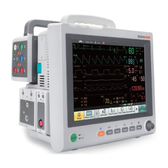
    PR monitoring (Refer to Chapter 11 Monitoring PR for more information.) NIBP monitoring (Refer to Chapter 12 Monitoring NIBP for more information.) Alarm (Refer to Chapter 4 Alarms for more information.) 3.1 Overview 3.1.1 Main Unit Front View elite V5/ elite V6 - 15 -...
  • Page 31 Patient Monitor User Manual Basic Operation elite V8 Alarm mute indicator When the audible alarm is mute, the indicator is in red. Physiological alarm When a physiological alarm occurs, the indicator indicator lights on or flashes with different frequencies and colors reflecting the alarm level.
  • Page 32 Patient Monitor User Manual Basic Operation Technical alarm When a technical alarm occurs, the indicator indicator lights on or flashes with different frequencies and colors reflecting the alarm level. Display 17 inch color screen. Resolution: 1280×1024. Power supply switch Press it to turn the monitor on when the monitor is connected to the AC power supply, or press the key to turn the monitor off when the monitor is Battery indicator...
  • Page 33 Patient Monitor User Manual Basic Operation Side View elite V5/ elite V6 Compartment for SD card and Wi-Fi module (Wi-Fi module is optional) XM module snap-fix Plug-in module slots Speaker Recorder Battery compartment latch - 18 -...
  • Page 34 Patient Monitor User Manual Basic Operation elite V8 Compartment for optional device (wireless network module) XM module slot XM module snap-fix Plug-in module slots Contact Battery compartment latch Compartment for recorder NOTE: To avoid bad contact caused by dust accumulation, clean the contacts regularly by wiping them with a cotton swab moistened with alcohol.
  • Page 35 Patient Monitor User Manual Basic Operation Rear View elite V5/ elite V6 - 20 -...
  • Page 36 Patient Monitor User Manual Basic Operation Power cable safety Used to prevent the power cable from loosing latch or falling. Place the latch on the power cable and press it down firmly to ensure that it secures the power cable. AC power input Equipotential If the monitor is used together with other...
  • Page 37 Patient Monitor User Manual Basic Operation elite V8 - 22 -...
  • Page 38 Mainframe to the monitor. RS232 interface Connect it to communicate with other devices. Heat sink Anti-thief lock CAUTION Connect only the EDAN Parameter Amplifier Mainframe to the PAM connector. Do not connect any other device to this connector. - 23 -...
  • Page 39: Parameter Amplifier Mainframe

    Patient Monitor User Manual Basic Operation NOTE: If incomplete display occurs on the screen of an external display connecting to the monitor via the VGA output, adjust it with the button for automatic screen adapting of the external display, or refer to its user manual. The functions of nurse call, analog output and defibrillator synchronization are only available when the XM module is inserted in the monitor.
  • Page 40: Measurement Modules

    Patient Monitor User Manual Basic Operation Contact Handle PAM connector NOTE: To avoid bad contact caused by dust accumulation, clean the contacts regularly by wiping them with a cotton swab moistened with alcohol. 3.1.3 Measurement Modules Users can use a maximum of 8 measurement modules with the PAM and additional 3 modules in the integrated module slots in the monitor.
  • Page 41 12 V-CO module (sidestream): Respironics carbon dioxide module for sidestream 13 V-CO module (sidestream): EDAN carbon dioxide module for sidestream 14 V-RM module: Respiration mechanics module Example Module The structure of each plug-in module is similar: the module name is located at the bottom part;...
  • Page 42: Xm Module

    Patient Monitor User Manual Basic Operation Second module-specific key, such as the zero key for IBP. Module name. Plugging/ Unplugging Modules Users can plug and unplug modules during monitoring. To plug a module, insert the module until the lever on the module clicks into place. To unplug a module, press the lever upwards and pull the module out.
  • Page 43 Patient Monitor User Manual Basic Operation Overview of XM Module Setup key: press to enter the XM module setup menu. Zero key: press to enter the zero IBP menu NIBP start/ stop key: press to start or stop NIBP measurement. Indicator On: when the module works normally.
  • Page 44: Im20

    Patient Monitor User Manual Basic Operation 3.1.5 iM20 The monitor can be coupled with iM20 patient monitor, where iM20 acts as a multi-measurement module, providing the measurements, trends, and patient information for the monitor. iM20 is integrated with functions of multiple measurement modules of ECG, RESP, SpO , TEMP, IBP and NIBP.
  • Page 45 Patient Monitor User Manual Basic Operation 15 16 17 18 Department Measurement setup key Bed number Scroll left to display more shortcut keys Patient name Shortcut key area Patient type Symbol for AC power supply Alarm status area Symbol for battery status Symbol for alarm off Symbol for networking Measurement value...
  • Page 46: Using Keys

    Patient Monitor User Manual Basic Operation 3.2.1 Using Keys The monitor has four different types of keys. If the key sound is enabled, the monitor gives a normal key sound when the operation is valid. 3.2.1.1 Permanent Keys A permanent key is a graphical key that remains on the screen all the time to give you fast access to functions.
  • Page 47: Setting Parameters

    Patient Monitor User Manual Basic Operation Access the NIBP review Change the beat volume Access the ARR review Enter standby mode Switch to the trend screen Printer Setup Switch to the vital screen Enter night mode Select this item by the rotary knob to enable the touch Enter MEWS interface screen operation...
  • Page 48 Patient Monitor User Manual Basic Operation This menu displays the measurement modules which have been mounted in the XM module slot, three-slot module rack and PAM from top to bottom. Beside each measurement connector is the measurement label. The color in which a measurement connector appears matches the status of the measurement parameter.
  • Page 49: Activating / Deactivating A Parameter Measurement

    Patient Monitor User Manual Basic Operation 3.3.2 Activating / Deactivating a Parameter Measurement For different measurement parameters, approaches to parameter activation / deactivation may vary a little. Take the parameters ECG and NIBP in XM module for example: To activate / deactivate the ECG measurement, select the ECG connector in the XM module on the MeasureSet menu, and set the ECG measurement to on or off on the pop-up submenu.
  • Page 50: Operating Mode

    Patient Monitor User Manual Basic Operation The IBP module with a label conflict will not provide any measurement data; besides, the functions of setup, zeroing and calibrating are unavailable. To resolve the label conflict, you have to change the conflicting label into a non-conflicting one. Three resolutions are available: Resolution 1: Select the IBP channel with a label conflict on the screen and open the Options menu.
  • Page 51: Night Mode

    Patient Monitor User Manual Basic Operation 4. Continuous real-time recording will stop immediately, and other recording task will stop after current recording finishes. 5. MFM-CMS won’t update monitoring data, and will display monitor's standby mode. If network is disconnected, monitor will make request for connection. 6.
  • Page 52: Nfc Mode

    Patient Monitor User Manual Basic Operation 3. The connected iM20 enters into privacy mode simultaneously. 4. Audio alarm paused status discontinues. Audio alarm off, alarm off, alarm reset and alarm latch status are not influenced. The monitor exits privacy mode in any of the conditions: 1.
  • Page 53: Changing Monitor Settings

    Patient Monitor User Manual Basic Operation 3.5 Changing Monitor Settings 3.5.1 Adjusting Screen Brightness To change the screen brightness: Select the shortcut key on the screen directly, or Select Menu > Common Function > Brightness, and select the appropriate setting for the screen brightness.
  • Page 54: Checking Your Monitor Version

    Patient Monitor User Manual Basic Operation 3.7 Checking Your Monitor Version To check the monitor version, please select Menu > Common Function > About to check the monitor software revision. 3.8 Networked Monitoring Your monitor can be connected to the wired network and the wireless network. If the monitor is networked, a network symbol is displayed on the screen.
  • Page 55: Disabling The Touch Screen

    Patient Monitor User Manual Basic Operation 3.11 Disabling the Touch Screen The user can disable touch screen operation by selecting and holding the permanent key for three seconds. A message of Screen Locked and the symbol will be displayed at the bottom of screen.
  • Page 56: Chapter 4 Alarms

    Patient Monitor User Manual Alarms Chapter 4 Alarms WARNING A potential hazard can exist if different alarm presets are used for the same or similar equipment in any single area, e.g. an intensive care unit or cardiac operating room. 4.1 Alarm Category The monitor provides two types of alarm: physiological alarms and technical alarms.
  • Page 57 Patient Monitor User Manual Alarms a medium priority alarm condition. Failure to respond to the cause of the alarm condition is likely to result in discomfort or reversible minor injury of the patient. Alarm Sound: The high/medium/low-level alarms are indicated by the system in following different audio ways: Alarm Level Prompt Mode is “DO-DO-DO------DO-DO, DO-DO-DO------DO-DO”, which...
  • Page 58: Controlling Alarm

    Patient Monitor User Manual Alarms 4.3 Controlling Alarm 4.3.1 Setting Parameter Alarm Parameter alarm settings including alarm switch, alarm record, alarm level and alarm limit are available on the respective alarm setup menu for each parameter. To access the menu for parameter alarm settings, use the shortcut key or select Menu >...
  • Page 59: Audio Alarm Paused

    Patient Monitor User Manual Alarms 4.3.2 Audio Alarm Paused You can temporarily prevent alarms from sounding by pressing the hardkey on the front panel or pressing shortcut key on the screen. You can set the alarm pause time as desired. The default alarm pause time is 120 s. 1.
  • Page 60: Alarm Reset

    Patient Monitor User Manual Alarms Pressing the hardkey again can resume the audio alarm. NOTE: If a new alarm occurs during the audio alarm off period, the new alarm will not be sounding. 4.3.4 Alarm Reset Select the shortcut key Alarm Reset on the screen directly.
  • Page 61: Network Disconnected Alarms

    Patient Monitor User Manual Alarms In Menu > Maintenance > User Maintain > Alarm Setup, SpO Sensor Off and ECG Lead Off alarm level can be adjusted as High, Med. or Low. These alarm levels are defaulted to be Low. 4.6 Network Disconnected Alarms To configure the network disconnected alarms, select Menu >...
  • Page 62: Chapter 5 Alarm Information

    Patient Monitor User Manual Alarm Information Chapter 5 Alarm Information 5.1 Physiological Alarm Information WARNING The physiological alarms including Asystole, Sustain VT, RESP APNEA, SpO Pulse, SpO Desat, CO APNEA, AG FiO Low, and AG APNEA cannot be turned off. Message Cause Alarm Level...
  • Page 63 Patient Monitor User Manual Alarm Information Message Cause Alarm Level Adult: RR interval for 5 consecutive QRS complex ≥ 1.5 s. Brady User-selectable Pediatric/neonatal: RR interval for 5 consecutive QRS complex ≥ 1 s. Basic: If HR < 120 bpm, no beats are detected for 1.75 times average RR interval;...
  • Page 64 Patient Monitor User Manual Alarm Information Message Cause Alarm Level User-selectable Meet tachycardia conditions, and QRS wave width ≥ Wide 160 ms. Tachy User-selectable 3 ≤ The number of consecutive ventricular beats < 5, Non-Sustain VT and ventricular HR ≥ 100 bpm. Atrial fibrillation alarm should meet below two conditions for 1 minute: User-selectable...
  • Page 65 Patient Monitor User Manual Alarm Information Message Cause Alarm Level RR High RR measuring value is above upper alarm limit. User-selectable RR Low RR measuring value is below lower alarm limit. User-selectable High User-selectable measuring value is above upper alarm limit. User-selectable measuring value is below lower alarm limit.
  • Page 66 Patient Monitor User Manual Alarm Information Message Cause Alarm Level Art MAP Low Art MAP measuring value is below lower alarm limit. User-selectable PA SYS High PA SYS measuring value is above upper alarm limit. User-selectable PA SYS measuring value is below lower alarm limit. User-selectable PA SYS Low PA DIA High...
  • Page 67 Patient Monitor User Manual Alarm Information Message Cause Alarm Level AwRR Low AwRR measuring value is below lower alarm limit. User-selectable EtCO (AG) EtCO (AG) measuring value is above upper alarm User-selectable High limit. EtCO (AG) measuring value is below lower alarm EtCO (AG) User-selectable...
  • Page 68: Technical Alarm Information

    Patient Monitor User Manual Alarm Information Message Cause Alarm Level FiSEV Low FiSEV measuring value is below lower alarm limit. User-selectable EtDES High EtDES measuring value is above upper alarm limit. User-selectable EtDES measuring value is below lower alarm limit. User-selectable EtDES Low FiDES High...
  • Page 69 Patient Monitor User Manual Alarm Information Message Cause Alarm Level Action Taken 1) The drive electrode or more than one ECG limb electrode falls off the skin; ECG Lead Off 2) ECG cables fall off the Make sure that all monitor.
  • Page 70 Patient Monitor User Manual Alarm Information Message Cause Alarm Level Action Taken ECG measuring signal is Signal beyond measuring range. Exceeded Check lead connection patient condition ECG measuring signal is ECG Noise greatly interrupted. Stop measuring function of ECG ECG module failure or module, and notify ECG Comm Fail High...
  • Page 71 Patient Monitor User Manual Alarm Information Message Cause Alarm Level Action Taken Check whether the patient is breathing normally. Take measures to help the patient breathe normally when No RESP waveform can be necessary. RESP Cardiac detected due to apnea or High patient is breathing Artifact...
  • Page 72 There is interference with Check the condition measurement signals of patient and avoid (EDAN Noisy Signal due to patient movement, patient movement; module) ambient light, electrical make sure the cable interference or else.
  • Page 73 Patient Monitor User Manual Alarm Information Message Cause Alarm Level Action Taken Notify biomedical Pressure has exceeded the NIBP Aux Excessive engineer second safety limit High Pressure manufacturer’s specified. service staff. Measure again or Measuring time NIBP Time Out use other measuring exceeded the specified time.
  • Page 74 Patient Monitor User Manual Alarm Information Message Cause Alarm Level Action Taken Make sure that the Signal noise is too large or patient under pulse rate is not regular due NIBP Interference monitoring to the patient movement. motionless. Fail to deflate normally Test again.
  • Page 75 Patient Monitor User Manual Alarm Information Message Cause Alarm Level Action Taken Check the catheter IBP catheter falls off due to High connection IBP Catheter Off patient movement. reconnect it. Malfunction in the IBP Replace IBP Sensor Err sensor or in the extension Medium sensor cable.
  • Page 76 Patient Monitor User Manual Alarm Information Message Cause Alarm Level Action Taken module failure AG Comm Fail High communication failure. concentration Out Of Range exceeds the accuracy range High of AG module. Stop measuring concentration function exceeds the accuracy range High O Out Of Range module, and notify...
  • Page 77 Patient Monitor User Manual Alarm Information Message Cause Alarm Level Action Taken Perform 1) Mainstream: The airway zeroing after adapter replaced replacing without a zeroing. adapter. 2) More than 2 anesthetic Reduce agents are present in the number breathing circuit. Medium Unreliable anesthetic...
  • Page 78 Check module: The cannula is off whether the adapter or disconnected. properly connected Check Adapter 2) For the EDAN CO replace the adapter. module: The water trap is disconnected or not properly 2) For the EDAN connected. module: Properly connect the water trap.
  • Page 79 Patient Monitor User Manual Alarm Information Message Cause Alarm Level Action Taken Water trap of SideStream is Make sure the gas High Occlude occluded. exhaust works well 1) Disconnection between the V-BIS module and BISx Properly connect BIS Comm Fail device.
  • Page 80 Patient Monitor User Manual Alarm Information Message Cause Alarm Level Action Taken The sensor can be used as long as it passes impedance check, BIS Sensor Expired The sensor expired. which, however, affect measurements. Replace the sensor if necessary. The sensor has been used BIS No More Uses too many times and cannot Replace the sensor.
  • Page 81 Patient Monitor User Manual Alarm Information Message Cause Alarm Level Action Taken Artifact, such those Attempt to identify BIS Artifact generated by motion or eye eliminate blinks. artifact source. Check if the module properly connected. Stop using measuring RM Comm Fail RM module failure High function...
  • Page 82 Patient Monitor User Manual Alarm Information Message Cause Alarm Level Action Taken Check whether the The cannula is off or adapter is properly (RM) Check Adapter disconnected. connected replace the adapter. (RM) Sensor Stop using module failure High Faulty measuring function module, measure value exceeds notify...
  • Page 83 Patient Monitor User Manual Alarm Information Message Cause Alarm Level Action Taken Make sure the No.1 The No.1 lead on the left is ICG L1 Lead Off lead on the left is off. properly connected. Make sure the No.1 The No.1 lead on the right is ICG R1 Lead Off lead on the right is off.
  • Page 84 Patient Monitor User Manual Alarm Information Message Cause Alarm Level Action Taken Battery External device battery is Replace or charge Medium Depleted depleted. the battery. Because electrode position is Check the electrode wrong, electrode is not well and cable to confirm fixed on skin or patient skin connection Skin resistance too...
  • Page 85 Patient Monitor User Manual Alarm Information Message Cause Alarm Level Action Taken Make sure temp External device’s temp sensor well sensor signal over flow and connected NMT Temp. Value exceed rated measurement temperature Out Of Range range. within measurement range, In PTC mode, the patient Check the patient PTC error...
  • Page 86: Prompts

    Patient Monitor User Manual Alarm Information Message Cause Alarm Level Action Taken Battery1 Current Battery discharge Too High over-current Battery2 Current Battery discharge Too High over-current Stop using battery and notify Battery1 Charge Battery over-voltage the manufacturer’s Voltage Too High during charging service staff.
  • Page 87 Patient Monitor User Manual Alarm Information Message Cause The QRS template building required for Arr. Analysis is ECG ARR Learning in process. ExtremeTachy Off Extreme Tachycardia alarm is set to Off. ExtremeBrady Off Extreme Bradycardia alarm is set to Off. V-Tach Off V-Tach alarm is set to Off.
  • Page 88 Patient Monitor User Manual Alarm Information Message Cause Zero OK IBP completes zeroing. During the zeroing process, pressure fluctuation is Pulsatile Pressure Zero Fail. excessive. During the zeroing process, pressure value is beyond the Pressure out of normal range, Fail. zeroing range.
  • Page 89 Patient Monitor User Manual Alarm Information Message Cause AG Changing to Meas. Work Mode is switching to Measure from Standby. AG Agent Low Concentration Measured agent concentration is low. Usually it comes up if no single agent history is available AG Agent Calculate and a mixture situation occurs.
  • Page 90: Adjustable Range Of Alarm Limits

    User can set the range through User Maintain > Alarm Setup > SpO Desat Limit, Desat Limit should be less than or equal to SpO alarm low limit. PR alarm limits are listed as follows: unit (bpm) Adjustable Range PR (SpO EDAN 30~300 Nellcor 30~300 PR (NIBP) EDAN 40~240...
  • Page 91 Patient Monitor User Manual Alarm Information NIBP alarm limits are listed as follows: unit: mmHg, kPa (1 mmHg = 0.133 kPa) EDAN module: Patient Type Adjustable Range 40~270 10~215 20~235 40~230 10~180 20~195 40~135 10~100 20~110 Omron module: Patient Type...
  • Page 92 Patient Monitor User Manual Alarm Information TEMP alarm limits are listed as follows: Adjustable Range 0 °C (32 ºF)~50 °C (122 ºF) 0 °C (32 ºF)~50 °C (122 ºF) High limit: 0.1 °C (32.18 ºF)~50 °C (122 ºF) IBP alarm limits are listed as follows: unit (mmHg) Adjustable Range 0~300 RAP/ LAP/ CVP/ICP...
  • Page 93 Patient Monitor User Manual Alarm Information Dräger Minimodule Adjustable Range FiCO EtCO 0%~13.6% 18.0%~100.0% / FiN O/ EtN 0%~100.0% EtDes/ FiDes 0%~20.0% EtIso/ FiIso/ EtHal/ FiHal 0%~8.5% EtSev/ FiSev/ EtEnf/ FiEnf 0%~10.0% AwRR 0 rpm~100 rpm BIS alarm limits are listed as follows: Adjustable Range 0~100 RM alarm limits are listed as follows:...
  • Page 94: Chapter 6 Managing Patients

    Patient Monitor User Manual Managing Patients Chapter 6 Managing Patients 6.1 Admitting a Patient The monitor displays physiological data and stores it in the trends as soon as a patient is connected. This allows you to monitor a patient who is not yet admitted. It is however important to admit patients properly so that you can identify your patient on recordings, reports, and networked devices.
  • Page 95: Patient Category And Paced Status

    Patient Monitor User Manual Managing Patients 6.1.1 Patient Category and Paced Status The patient category setting determines the algorithm which the monitor uses to process and calculate some measurements, the safety limits that are applied for some measurements, and the alarm limit ranges.
  • Page 96: Central Monitoring System

    Patient Monitor User Manual Managing Patients 6.5 Central Monitoring System The monitor can be connected to the central monitoring system. Through the network: 1. The monitor sends patient information, real-time monitoring or measurement data to the central monitoring system. 2. The real-time monitoring information is displayed on the central monitoring system as the same to the monitor, and the central monitoring system can perform some bilateral control.
  • Page 97: Chapter 7 User Interface

    Patient Monitor User Manual User Interface Chapter 7 User Interface 7.1 Setting Interface Style The user can set the interface based on the requirement, and the set options include the following: Sweep of the waveform. Parameters needing to be monitored. Change to some settings may have the risk, so only the authorized person can change them.
  • Page 98: Viewing Trend Screen

    Patient Monitor User Manual User Interface 7.5 Viewing Trend Screen To view the trend screen, the user can press the shortcut key on the screen directly or select Menu > Display Setup > View Selection > TrendScreen. 7.6 Viewing OxyCRG Screen To view the oxyCRG screen, the user can press the shortcut key on the screen directly or select Menu >...
  • Page 99: Viewing The Vital Screen

    Patient Monitor User Manual User Interface 7.8 Viewing the Vital Screen To view the vital screen, the user can press the shortcut key on the screen directly or select Menu > Display Setup > View Selection > Vital. 7.9 Viewing the Bed View Window The Bed View window allows you to view one waveform, numeric information of all parameters and alarm information from another bed on the same network.
  • Page 100: User Configuration

    Patient Monitor User Manual User Interface 7.11 User Configuration Select Menu > Maintenance > User Maintain, enter the required password ABC, users can save the current monitor’s configuration, delete the saved user configuration and rename it. Three pieces of user configuration can be saved in the monitor. Users can select as desire. The one labeled with ●...
  • Page 101: Chapter 8 Monitoring Ecg

    Patient Monitor User Manual Monitoring ECG Chapter 8 Monitoring ECG 8.1 Overview The electrocardiogram (ECG) measures the electrical activity of the heart and displays it on the monitor as a waveform and a numeric. This chapter also tells you about arrhythmia monitoring and ST monitoring.
  • Page 102 Patient Monitor User Manual Monitoring ECG WARNING If the ECG signal exceeds the measuring range, the monitor will indicates it by a message “ECG Signal Exceeded”. In order to avoid being burnt, please keep the electrodes far away from the radio knife while using electrosurgical equipment.
  • Page 103: Ecg Display

    Patient Monitor User Manual Monitoring ECG field density exceeding 3 v/m may cause measurement error in various frequencies. It is accordingly suggested that do not use equipment generating electrical radiation near ECG/RESP monitoring devices. If the pacemaker signals are beyond the claimed range, the heart rate may be calculated incorrectly.
  • Page 104: Changing The Ecg Filter Settings

    Patient Monitor User Manual Monitoring ECG X0.25: make size of ECG signal waveform of 1mV become 2.5 mm; X0.5: make size of ECG signal waveform of 1mV become 5 mm; X1: make size of ECG signal waveform of 1mV become 10 mm; X2: make size of ECG signal waveform of 1mV become 20 mm;...
  • Page 105: Monitoring Procedure

    CAUTION To protect the monitor from damage during defibrillation, for accurate ECG information and to protect against noise and other interference, use only ECG electrodes and cables specified by EDAN. 8.5.3 Selecting Lead Type To change the lead type, please: 1.
  • Page 106: Installing Electrodes

    Patient Monitor User Manual Monitoring ECG 8.5.4 Installing Electrodes NOTE: The following table gives the corresponding lead names used in Europe and America respectively. (Lead names are represented by R, L, F, N, C, C1-C6 in Europe, whose corresponding lead names in America are RA, LA, LL, RL, V, V1-V6.) AHA (American Standard) IEC (Europe Standard) Electrode Labels...
  • Page 107 Patient Monitor User Manual Monitoring ECG 8.5.4.2 Electrode Placement for 5-Lead Take the American standard for example; see the following figure: ■ RA placement: directly below the clavicle and near the right shoulder. ■ LA placement: directly below the clavicle and near the left shoulder. ■...
  • Page 108 Patient Monitor User Manual Monitoring ECG V-Electrode Placement for 5-Lead 8.5.4.3 Electrode Placement for 12-Lead Take the American standard for example; the 12-lead electrodes should be placed as follows: The limb electrodes are placed in the same position as the 3-lead placement. ■...
  • Page 109: Ecg Menu Setup

    Patient Monitor User Manual Monitoring ECG 8.5.4.4 Recommended ECG Lead Placement for Surgical Patients WARNING When using Electrosurgery (ES) equipment, leads should be placed in a position in equal distance from Electrosurgery electrotome and the ES grounding plate to avoid cautery. Electrosurgery equipment wire and ECG cable must not be tangled up.
  • Page 110: Setting Beat Source

    Patient Monitor User Manual Monitoring ECG to PR as the alarm source if: –a valid ECG lead can no longer be measured and –a PR source is switched on and available. The monitor then uses the pulse rate from the measurement currently active as system pulse. While PR is the alarm source, all arrhythmia and ECG HR alarms are switched off.
  • Page 111: Setting Pace Status

    Patient Monitor User Manual Monitoring ECG NOTE: If 3 Leads is selected in the ECG Setup menu, only Normal can be selected for Display in the sub-menu. In 12 Leads display interface, the filter can only be set to Diagnosis. 8.6.5 Setting Pace Status It is important to set the paced status correctly when you start monitoring ECG.
  • Page 112: Ecg Waveform Settings

    Select Menu > Maintenance > User Maintain > Other Setups > 12 Leads Activate in order to get the SN number which is supposed to be supplied to EDAN for a corresponding password. Enter the password on the above-mentioned interface and restart the monitor, and the 12-lead ECG monitoring function will be activated.
  • Page 113: Waveform Durations And Isoelectric Segments

    Patient Monitor User Manual Monitoring ECG and RV5+SV1 amplitude. The interpretation function provides the automatic analysis of hundreds of abnormal cases, such as arrhythmia, AV block, IVCD (Intraventricular Conduction Block), myocardial infarction, ventricular hypertrophy and atrial enlargement, ST-T abnormality and electrical axis deviation. 8.7.3 Waveform Durations and Isoelectric Segments Between the global onset and offset of the QRS-complex, signal parts with a duration of more than 6 ms and amplitude not exceeding 20 μV should be defined as isoelectric segments.
  • Page 114: Setting St Analysis

    Patient Monitor User Manual Monitoring ECG doctor wants to observe the waveform to evaluate ST segment result, it is recommended to use the ST template for observation, as it is not affected by the filter mode. If the real-time waveform displayed on the interface is used to evaluate ST segment result, it is recommended to select Diagnosis mode.
  • Page 115: About St Measurement Points

    Patient Monitor User Manual Monitoring ECG 8.8.3 About ST Measurement Points The ST value for each beat complex is the vertical difference between the ISO point and the ST point, as shown in the diagram below. The isoelectric (ISO) point provides the baseline, and the ST point is at the midpoint of the ST segment.
  • Page 116 Patient Monitor User Manual Monitoring ECG When iM20 (as sub-monitor) is connected to VX series monitor, if iM20 supports Advanced ARR, it will synchronize with elite VX series monitor; if not, Basic ARR will be adopted. When XM module or iM20 has been inserted into VX series monitor, user unplugs the inserted one from the monitor and reinserts another one, if the ARR analyses of newly inserted one is inconsistent with that of the previous one, the monitor will pop up a prompt to notify user that ARR analysis is switched to Basic or Advanced.
  • Page 117 Patient Monitor User Manual Monitoring ECG ARR Alarms Occurring Condition Pacer No QRS complex detected in 300 ms after a pace pulse. Capture Pacer No pace pulse detected in 1.75 times RR interval after a QRS complex. Pacing Basic: 5 consecutive ventricular beats, and ventricular HR < 40 bpm. Vent Brady Advanced: 5 consecutive ventricular beats, and ventricular HR <...
  • Page 118 Patient Monitor User Manual Monitoring ECG ARR Alarms Occurring Condition Multiform Different forms of ventricular premature beats are detected in 15 beats. PVCs The single ventricular premature beat between 2 sinus beats with normal IPVC interval occurs more than or equal to 3 times within 30 s. The dominant rhythm of N, A, N, A, N, A, and the rhythm number exceeds the number of threshold value that has been set (N = supraventricular beat, A Bigeminy...
  • Page 119 Patient Monitor User Manual Monitoring ECG the wrong classification. Ventricular heartbeat should have a different appearance from “normal heartbeat”. Physicians should be more alert to these patients. NOTE: Heart rate reading may be affected by cardiac arrhythmias. Do not rely entirely on heart rate alarms when monitoring patients with arrhythmia.
  • Page 120: Arr Analysis Menu

    Patient Monitor User Manual Monitoring ECG 8.9.2 ARR Analysis Menu 8.9.2.1 Switching ARR Analysis On and Off To switch ARR Analysis on or off, in the ECG Setup menu, select ARR Analysis to toggle between On and Off from the popup interface. 8.9.2.2 ARR Alarm Setup Select ECG Setup >...
  • Page 121 Patient Monitor User Manual Monitoring ECG ARR Alarm Range PAC Bigeminy 3/min to 50/min PAC Trigeminy Pauses/min High 1/min to 20/min Sustain VT 15 s to 45 s ExtremeBrady 15 bpm to 60 bpm Low Voltage(Limb) 0.3 mV to 0.8 mV 8.9.2.4 ARR Selflearning Pick this item ARR Selflearn to start a learning procedure, and ECG ARR Learning is displayed on the screen.
  • Page 122: Chapter 9 Monitoring Resp

    Patient Monitor User Manual Monitoring RESP Chapter 9 Monitoring RESP 9.1 Overview The monitor measures respiration from the amount of thoracic impedance between two ECG electrodes. The change of impedance between the two electrodes, (due to the thoracic movement), produces a respiratory waveform on the screen. 9.2 RESP Safety Information WARNING If you do not set the Hold High and Hold Low for the respiration correctly in manual...
  • Page 123: Electrode Placement For Monitoring Resp

    Patient Monitor User Manual Monitoring RESP WARNING When ECG electrode is placed on patient’s limb, the impedance respiration may be unreliable. Respiration measurement cannot be performed when ESU is used. NOTE: The RESP monitoring is not recommended to be used on patients who are very active, as this can cause false alarms.
  • Page 124: Abdominal Breathing

    Patient Monitor User Manual Monitoring RESP 9.6 Abdominal Breathing Some patients with restricted chest movement breathe mainly abdominally. In these cases, you may need to place the left leg electrode on the left abdomen at the point of maximum abdominal expansion to optimize the respiratory wave.
  • Page 125: Chapter 10 Monitoring Spo

    Patient Monitor User Manual Monitoring SpO Chapter 10 Monitoring SpO 10.1 Overview is used to measure arterial blood oxygen saturation, which is the percentage of oxyhemoglobin in the arterial blood. SpO parameter can also provide pulse rate (PR) and a plethysmogram wave (Pleth).
  • Page 126: Measuring Spo

    Patient Monitor User Manual Monitoring SpO WARNING Use only EDAN permitted sensors and extension cables with the monitor. Other sensors or extension cables may cause improper monitor performance and/or minor personal injury. High oxygen levels may predispose a premature infant to retrolental fibroplasia. If this is a consideration do NOT set the high alarm limit to 100%, which is equivalent to switching the high limit alarm off.
  • Page 127: Measurement Limitations

    Patient Monitor User Manual Monitoring SpO Mounting of the Sensor WARNING Inspect the application site every two to three hours to ensure skin quality and correct optical alignment. If the skin quality changes, move the sensor to another site. Change the application site at least every four hours.
  • Page 128: Assessing The Validity Of A Spo Reading

    Patient Monitor User Manual Monitoring SpO • placement of the sensor on an extremity with a blood pressure cuff, arterial catheter, or intravascular line • electromagnetic interference Loss of pulse signal can occur for the following reasons: • the sensor is applied too tightly •...
  • Page 129: Spo Alarm Delay

    CO-oximeter measurements. The volunteer population in the studies are composed of healthy men and women from age 19 to 37 (for EDAN SpO module), from 18 to 50 (for Nellcor SpO module), with various skin pigmentations.
  • Page 130: Setting Pitch Tone

    Patient Monitor User Manual Monitoring SpO to On in SpO Setup menu to lock the SpO alarm status until the NIBP measurement ends. If NIBP Simul is set to Off, low perfusion caused by NIBP measurement may lead to inaccurate readings and therefore cause false physiological alarms.
  • Page 131: Satseconds "Safety Net

    Patient Monitor User Manual Monitoring SpO seconds and then to 84 for 6 seconds. The resulting SatSeconds values are shown below: Seconds SatSeconds × × × Total SatSeconds After approximately 10.7 seconds, a SatSeconds alarm will be triggered, because the limit of 50 SatSeconds has been exceeded.
  • Page 132: Chapter 11 Monitoring Pr

    Patient Monitor User Manual Monitoring PR Chapter 11 Monitoring PR 11.1 Overview The pulse numeric counts the arterial pulsations that result from the mechanical activity of the heart in beats per minute (bpm). You can obtain a pulse from any measured SpO signal or any arterial pressure.
  • Page 133: Chapter 12 Monitoring Nibp

    Patient Monitor User Manual Monitoring NIBP Chapter 12 Monitoring NIBP 12.1 Overview This monitor uses the oscillometric method for measuring NIBP. It can be used for adult, pediatric and neonatal patients. It is also intended for use with pregnant, including pre-eclamptic patients.
  • Page 134 Patient Monitor User Manual Monitoring NIBP WARNING Do not attach the cuff to a limb being used for IV infusions as the cuff inflation can block the infusion, potentially causing harm to patient. Do not apply the cuff to a limb where intravascular access or therapy, or an arterio-venous (A-V) shunt is present, otherwise, it may result in injury to the patient.
  • Page 135: Measurement Limitations

    Patient Monitor User Manual Monitoring NIBP 12.3 Measurement Limitations Measurements are impossible with pulse rate extremes of less than 40 bpm or greater than 240 bpm, or if the patient is on a heart-lung machine. The measurement may be inaccurate or impossible in the following situations: A regular arterial pressure pulse is hard to detect.
  • Page 136 Patient Monitor User Manual Monitoring NIBP pressure against the cuff. 2. Connect the air hose to the connector on XM module and switch on the monitor. Apply the blood pressure cuff to the patient's arm or leg and follow the instructions below. -Ensure that the cuff is completely deflated.
  • Page 137: Operation Prompts

    Patient Monitor User Manual Monitoring NIBP 12.5.1 Operation Prompts 1. Manual Measuring Access the NIBP Setup menu and set the Measure Mode item to Manual. Then press the button on the front panel or shortcut key on the screen to start a manual measurement. 2.
  • Page 138: Leakage Test

    For EDAN module: The system will automatically inflate the pneumatic system to about 180 mmHg. After 20 seconds to 40 seconds, if system leakage has detected, the system will automatically open the deflating valve to stop the leak test and indicates NIBP Leak.
  • Page 139: Setting Inflation Mode

    Patient Monitor User Manual Monitoring NIBP pneumatic system to remain above 10mmHg for 180 seconds. When this safety time limit is exceeded, the valves will open releasing the pressure. Subtract P2 from P1 and this is the leak rate per minute. If the alarm information NIBP Leak appears, it indicates that the airway may have air leaks.
  • Page 140: Chapter 13 Monitoring Temp

    Patient Monitor User Manual Monitoring TEMP Chapter 13 Monitoring TEMP 13.1 Overview Body temperature is measured by means of a thermistor probe (a semiconductor whose resistance changes with temperature) that is applied to the skin or to the rectum. Two TEMP probes can be used simultaneously to measure two TEMP values, and get the temperature difference.
  • Page 141: Switching T1/T2 On/Off

    Patient Monitor User Manual Monitoring TEMP 13.3 Switching T1/T2 On/Off In Menu > System Setup > Module Switch or select shortcut key ModuleSet > Module Switch, T1 or T2 can be switched on/off separately and won’t be affected by each other. 13.4 TEMP Monitoring Setup With a reusable TEMP probe you can plug the probe directly into the TEMP connector on XM module.
  • Page 142: Chapter 14 Monitoring Ibp

    Patient Monitor User Manual Monitoring IBP Chapter 14 Monitoring IBP 14.1 Overview IBP is measured by means of a catheter inserted directly into the circulatory system. A pressure transducer connected to the catheter converts the mechanical force exerted by the blood into an electrical signal, which is displayed graphically as pressure versus time on a monitor screen or numerically on digital display.
  • Page 143: Monitoring Procedures

    Patient Monitor User Manual Monitoring IBP WARNING Mechanical shock to the invasive blood pressure transducer may cause severe shifts in zero and calibration, and then cause erroneous readings. The longest duration of IBP arterial catheterization is 7 days. NOTE: Use only the pressure transducer listed in the IBP Accessories. If measuring intracranial pressure (ICP) on a sitting patient, adjust the transducer on the same level with the top of the patient’s ear.
  • Page 144: Selecting A Pressure For Monitoring

    Patient Monitor User Manual Monitoring IBP 14.3.1 Selecting a Pressure for Monitoring Tell the monitor which pressure you want to monitor by selecting its pressure label. The label is a unique identifier for each type of pressure. When you choose a label, the monitor uses that label’s stored settings, for example color, wave scale and alarm settings.
  • Page 145: Troubleshooting The Pressure Zeroing (Taking Art For Example)

    Patient Monitor User Manual Monitoring IBP 14.3.3 Troubleshooting the Pressure Zeroing (Taking Art for Example) The status message lists the probable cause of an unsuccessful calibration. Cause Corrective Action Art ZERO FAIL Make sure that the transducer is not attached to the patient. Art SENSOR OFF, FAIL Make sure that transducer is not off, and then proceed zeroing.
  • Page 146: Measuring Pawp

    Patient Monitor User Manual Monitoring IBP 14.6 Measuring PAWP PAWP, Pulmonary Artery Wedge Pressure, used to assess the cardiac function, is obtained by introducing a balloon-tipped pulmonary artery flotation catheter into the pulmonary artery. When the catheter is in one of the smaller pulmonary arteries, the inflated balloon occludes the artery allowing the monitor to record changes in the intrathoracic pressures that occur throughout the respiration cycle.
  • Page 147: Calculating Cpp

    Patient Monitor User Manual Monitoring IBP WARNING Due to the short measurement delay, do not use sidestream CO as a direct reference to determine the end point of the breath in the pressure curve. If the balloon is not inflated but the pulmonary artery floating catheter enters the wedge position, the pulmonary artery pressure waveform becomes wedge-shaped.
  • Page 148 Patient Monitor User Manual Monitoring IBP WARNING In below situations, the calculated PPV value may be inaccurate: the respiration rate is lower than 8 rpm the tidal volume during ventilation is lower than 8 ml/kg patients have acute right ventricular functional disorder (pulmonary heart disease) PPV measurement has been validated only for adult patients.
  • Page 149: Chapter 15 Monitoring Co

    Identifying CO Modules Sidestream CO modules (From left to right are the Respironics CO module and the EDAN CO module): Gas outlet Gas inlet Water trap holder...
  • Page 150: Co Safety Information

    Respironics module is not equipped with automatic air pressure compensation, before you start the CO measurement for the first time, you must set the correct altitude. Incorrect altitude settings can cause incorrect CO readings. EDAN EtCO module is equipped with automatic air pressure compensation, and manual setting is not required.
  • Page 151: Monitoring Procedures

    Patient Monitor User Manual Monitoring CO 15.3 Monitoring Procedures 15.3.1 Zeroing the Sensor For the EDAN EtCO module: EDAN EtCO module itself has automatic zero function, only when the measurement is abnormal or measurement results are doubtful, the user can perform manual zero as following steps: 1.
  • Page 152 When replacing the water trap or suspecting the measurement value, please check if the O-rings of the water trap holder are normal and well installed. If the O-rings get damaged or loose, contact EDAN’s service staff. To prevent the module from abnormal work, please ensure the water trap detection button is not mistakenly touched.
  • Page 153 Patient Monitor User Manual Monitoring CO Air Adapter For non-intubated patients: Place the nasal cannula onto the patient. Place the Nasal Cannula NOTE: You must perform a zero calibration as described in this procedure each time the ambient temperature changes more than 10 °C (for example during transport). Always connect the airway adapter to the sensor before inserting the airway adapter into the breathing circuit.
  • Page 154: Mainstream Co Module

    Patient Monitor User Manual Monitoring CO 15.3.2.2 Removing Exhaust Gases from the System WARNING Do not connect the exhaust tube to the ventilator circuit, connect the outlet to a scavenging system, cross infection can occur if sampling gas is returned to the breathing system.
  • Page 155: Setting Co Corrections

    O and Helium in the mixture all influence CO absorption. If values seem inaccurately high or low, check that the monitor is using the appropriate corrections. For the EDAN sidestream module, the following items are available in the CO Other Setup menu: N O Compen., O...
  • Page 156: Setting Apnea Alarm Time

    Patient Monitor User Manual Monitoring CO NOTE: Make sure compensation value is correctly set, otherwise the measurement accuracy may be affected. 15.5 Setting Apnea Alarm Time This determines the time limit after which the monitor gives an alarm if the patient stops breathing.
  • Page 157: Chapter 16 Monitoring C.o

    Patient Monitor User Manual Monitoring C.O. Chapter 16 Monitoring C.O. 16.1 Overview The cardiac output (C.O.) measurement invasively measures cardiac output and other hemodynamic parameters by using the Thermodilution method. The Thermodilution method is to inject a cold solution into the blood circulation system and measure the temperature changes caused by the cold solution through the thermistor of the pulmonary artery floating catheter, and the C.O.
  • Page 158: Monitoring

    Patient Monitor User Manual Monitoring C.O. NOTE: To replace the catheter thermistor, please enter the catheter computation coefficient into the Constant item according to the instruction. Please set injection switch well. The calculation of the cardiac output is based on the state of the injection switch at the end of the measurement.
  • Page 159 Patient Monitor User Manual Monitoring C.O. 3. Open the patient information window to confirm the patient’s height and weight. 4. In C.O. Setup menu, set: C.O. Constant: The computation constant is associated with catheter and injectate volume. When the catheter is changed, please adjust Constant in the C.O. Setup menu based on product description provided by the manufacturer.
  • Page 160 Patient Monitor User Manual Monitoring C.O. Injectate Temperature Y axis: Change the scale Y (temperature) value. Three modes are available: 0 °C to 0.5 Start time of the measurement °C, 0 °C to 1 °C, 0 °C to 2.0 °C. Adjust the Prompt message area scale by the temperature differences.
  • Page 161 Patient Monitor User Manual Monitoring C.O. ① ③ ② Window for C.O. Edit Contents displayed in the window: Six curves of the six measurements and C.O. value ① Average value of C.O. ② Average value of CI ③ WARNING Make sure that the computational constant for the measurement is appropriate to the catheter used.
  • Page 162: Blood Temperature Monitoring

    Patient Monitor User Manual Monitoring C.O. 16.4 Blood Temperature Monitoring Blood temperature monitoring can function when C.O. measurement is not taken. The blood temperature is measured by the thermistor situated in the distal end of the flotation catheter in the pulmonary artery.
  • Page 163: Chapter 17 Monitoring Ag

    Patient Monitor User Manual Monitoring AG Chapter 17 Monitoring AG 17.1 Overview The monitor uses ISA sidestream gas analyzer (hereinafter called ISA analyzer), Dräger AG sidestream Minimodule (hereinafter called Dräger Minimodule), and IRMA mainstream module (hereinafter called IRMA module) to monitor the anesthetic gas which can be used to measure the gases of adult, pediatric and neonatal patients during anesthesia, recovery and respiratory care.
  • Page 164: Safety Information

    Patient Monitor User Manual Monitoring AG 17.2 Safety Information 17.2.1 Safety Information for ISA Analyzer WARNING The ISA sidestream gas analyzer is intended for use by authorized healthcare professionals only. Use only Nomoline sampling lines manufactured by Masimo. The ISA analyzer must not be used with flammable anesthetic agents. Carefully route the sampling line to reduce the risk of patient entanglement or strangulation.
  • Page 165 Patient Monitor User Manual Monitoring AG WARNING 19 ISA sidestream gas analyzer is intended only as an adjunct in patient assessment. It must be used in conjunction with other assessments of clinical signs and symptoms. 20 Replace the sampling line if the sampling line input connector starts flashing red, or a “Sample line clogged”...
  • Page 166: Safety Information For Dräger Minimodule

    Patient Monitor User Manual Monitoring AG 17.2.2 Safety Information for Dräger Minimodule WARNING Dräger Minimodule is intended to be used by trained and authorized health care professionals only. Dräger Minimodule must not be used in areas where combustible or explosive gas mixtures are likely to occur.
  • Page 167: Safety Information For Irma Module

    Patient Monitor User Manual Monitoring AG WARNING 16 Do not spray the O-rings of the watertrap holder with silicon spray. Silicon can get into the measuring cuvette and influence the gas measurement permanently. 17 Always connect the gas exhaust of the medical device and anesthesia machine to the scavenging system.
  • Page 168 Patient Monitor User Manual Monitoring AG WARNING Disposable IRMA airway adapters shall not be reused. Used disposable airway adapters shall be disposed of in accordance with local regulations for medical wastes; otherwise, it may cause environmental contamination. Do not use the IRMA Adult/Pediatric adapter with infants as the adapter adds 6 ml dead space to the patient circuit.
  • Page 169: Monitoring Steps

    Patient Monitor User Manual Monitoring AG NOTE: For disposal of hospital waste such as accumulated fluids, calibration gases, sampled gases, where not otherwise specified, follow local regulations regarding disposal of hospital waste. 17.3 Monitoring Steps Nomoline Family Sampling Lines ISA samples gas from the respiratory circuit through the Nomoline Family sampling line at a rate of 50 sml/min, making measurements of CO possible for adult, pediatric and infant patients.
  • Page 170: Monitoring Steps For Isa Module

    Patient Monitor User Manual Monitoring AG Figure 2. For optimal water handling, always use T-adapters with the sampling point in the center of the adapter, as shown to the left above. NOTE: Using sample tubes or cannulas with larger inner diameter than 1 mm will increase ISA’s total system response time.
  • Page 171 Patient Monitor User Manual Monitoring AG 3 mmHg. If it has decreased more there is a major leakage in the ISA unit or in the Nomoline. Do not operate the ISA if there is a major leakage in the unit. 17.3.1.3 System Setup for Analyzer If your system is using the plug-in and measure ISA analyzer, please follow the setup instructions below:...
  • Page 172: Monitoring Steps For Dräger Minimodule

    Patient Monitor User Manual Monitoring AG 17.3.1.6 Maintenance Once every year, or whenever gas readings are questionable, perform a leakage check according to section 17.3.1.2 and verify gas readings with a reference instrument or with calibration gas. WARNING The Nomoline sampling lines are non-sterile devices. To avoid damage, do not autoclave any parts of the sampling line.
  • Page 173 Patient Monitor User Manual Monitoring AG 17.3.2.1 Zeroing The module purges and zeroes itself and does not need any interaction by the user. Waveforms flatline and parameter box values blank from the screen during this cycle. 17.3.2.2 MAC Calculation Standard MAC values 1 standard MAC is equal to the alveolar anesthetic concentration at one atmosphere (760 mmHg) at which 50% of all patients no longer respond to noxious stimuli.
  • Page 174: Monitoring Steps For Irma Module

    Patient Monitor User Manual Monitoring AG 17.3.3 Monitoring Steps for IRMA Module 1. Plug the IRMA connector into the IRMA input and switch the power on. 2. Snap the IRMA sensor head on the top of the IRMA airway adapter. It will click into place when properly seated.
  • Page 175 Patient Monitor User Manual Monitoring AG 17.3.3.1 Placement of IRMA Probe When connecting IRMA probe to an infant patient circuit, it is important to avoid a direct contact between the IRMA probe and the infant’s body. If, for whatever the reason, the IRMA probe is in direct contact with any parts of the infant’s body, an insulation material shall be placed between the IRMA probe and the body.
  • Page 176: Setting Apnea Alarm Time

    Patient Monitor User Manual Monitoring AG CAUTION The IRMA airway adapters are non-sterile devices. Do not autoclave the devices as this will damage them. Never immerse the IRMA probe in liquid. 17.3.3.5 Maintenance Gas readings should be verified at regular intervals with a reference instrument or by conducting the gas check.
  • Page 177: O 2 Compensations

    Patient Monitor User Manual Monitoring AG Blinking green light Zeroing in progress Steady blue light Anesthetic agent present Steady red light Sensor error Blinking red light Check adapter 17.7 O Compensations The following models need O compensation: IRMA AX+, ISA AX+. For the compensation details, please refer to the following table.
  • Page 178: Chapter 18 Monitoring Bis

    Patient Monitor User Manual Monitoring BIS Chapter 18 Monitoring BIS* *not available in U.S.A. 18.1 Overview Bispectral Index monitoring helps to monitor the hypnotic state of the brain based on acquisition and processing of EEG signals. The monitor processes raw EEG signals to produce a single number, namely BIS, which correlates with the patient's level of hypnosis.
  • Page 179 Patient Monitor User Manual Monitoring BIS BIS Range and Clinical State Awake Responds to normal voice Light/ Moderate Sedation May respond to loud commands or mild prodding/shaking General Anesthesia Low probability of explicit recall Unresponsive to verbal stimulus Deep Hypnotic State Burst Suppression Flat Line EEG Note: This chart reflects a general association between clinical state and BIS...
  • Page 180: Safety Information

    Patient Monitor User Manual Monitoring BIS BC: (BISx device used with Extend Sensor only) The BC numeric helps to quantify suppression, reported as the number of EEG bursts per minute, where an EEG burst is defined as a period of activity followed and preceded by inactivity (at least 0.5 second). The BC numeric is valid when SQI ≥...
  • Page 181 Patient Monitor User Manual Monitoring BIS WARNING The conductive parts of electrodes or sensor and connectors should not contact other conductive parts, including earth. To reduce the hazard of burns during use of brain-stimulating devices (e.g., transcranial electrical motor evoked potential), place stimulating electrodes as far as possible from the BIS sensor and make certain that sensor is placed according to package instructions.
  • Page 182: Bis Monitoring Setup

    RF electromagnetic fields and 1 Vrms for conducted disturbances induced by RF fields. Electromagnetic fields with field strengths above 1 V/m and conducted disturbances above 1 Vrms may cause erroneous measurements. Therefore EDAN recommends that you avoid using electrically radiating equipment in the close proximity of these measurements.
  • Page 183: Bis Continuous Impedance Check

    Patient Monitor User Manual Monitoring BIS blank side of the sensor tab (i.e. the side without the computer chip) should be facing up. CAUTION Ensure that the BISx device does not come into prolonged contact with your patient’s skin, as it may generate heat and cause discomfort. The BISx device may remain connected to a patient during defibrillation as long as the sensor is not located between the defibrillator pads.
  • Page 184: Bis Sensor Window

    Patient Monitor User Manual Monitoring BIS select BIS Setup > Sensor States and click Stop Sensor Check . 18.6 BIS Sensor Window To open the BIS sensor window, select Sensor States on the BIS Setup menu . The window may look slightly different on your monitor. The graphic in the BIS sensor window automatically adapts to show the type of sensor in use.
  • Page 185: Changing The Bis Smoothing Rate

    Patient Monitor User Manual Monitoring BIS Color Status Electrode-to-skin impedance Action Lead Off Electrode has no skin contact. Reconnect electrode, or check the sensor-to-skin contact. necessary, clean and dry skin. 18.7 Changing the BIS Smoothing Rate The smoothing rate defines how the monitor averages the BIS value. With the decline in smoothing rate, the monitor provides increased responsiveness to changes in the patient’s state.
  • Page 186: Chapter 19 Monitoring Rm

    Patient Monitor User Manual Monitoring RM Chapter 19 Monitoring RM* *not available in U.S.A. 19.1 Overview The monitor measures respiratory mechanics by connecting the RM module with the flow sensor to produce numerics and waveforms for flow, volume and pressure of respiratory gases in the airway.
  • Page 187: Safety Information

    Patient Monitor User Manual Monitoring RM – Cstatic (static compliance) – RAWi (airway resistance-inspired) – RAWe (airway resistance-expired) – NIP (negative inspiratory pressure) – RSBI (rapid shallow breathing index) – P (airway pressure at 100 msec after the start of inspiration) –...
  • Page 188 18 The use of portable and mobile radio frequency (RF) communications equipment can affect this and other pieces of medical equipment. 19 The use of accessories, sensors and cables other than those specified by EDAN may increase emissions or decrease immunity of the equipment.
  • Page 189 17 If interference does occur, correct it using one or more of the following measures: – Move the receiving device or increase separation between the equipment. – Consult EDAN or members of the hospital’s engineering department for more information. 18 The RM module is not intended for use in a hyperbaric chamber or an MRI (Magnetic Resonance Imaging) environment.
  • Page 190: Sensor Setup

    Patient Monitor User Manual Monitoring RM NOTE: Set the gas compensation on module startup, and whenever the nominal gas composition delivered to the patient is changed. This product and its accessories which have patient contact are free of latex. The following factors can influence CO and flow measurement: nitrous oxide, barometric pressure, temperature, humidity, airway pressure, O , helium and...
  • Page 191: Zero Calibration

    Patient Monitor User Manual Monitoring RM To ventilator To patient Neonatal CO /Flow Sensor with CO Sensor Attached NOTE: The flow or CO /flow sensor type is detected when the sensor is connected to the RM module. The flow sensor type is communicated to the monitor. Flow sensors are uniquely identifiable based on connector design.
  • Page 192: Changing The Concentration Of Inspired O

    Patient Monitor User Manual Monitoring RM using the manually entered gas concentrations. If the airway gas conditions are not properly set in the monitor, the measured flow will be incorrect. The measurement error is dependent on the airway gas conditions, flow rate and barometric pressure.
  • Page 193: Changing The Humidity Of The Inspired And Expired Gas

    Patient Monitor User Manual Monitoring RM 19.6.4 Changing the Humidity of the Inspired and Expired Gas Select RM Setup > Other Setups to open the Air Compensation window. Select the appropriate settings for the Fi Humidity and Et Humidity items. 19.7 RM Configuration The following settings are accessible on the RM Setup menu.
  • Page 194: Viewing Loops

    Patient Monitor User Manual Monitoring RM 19.8.1 Viewing Loops To view the respiratory loops, select Respiratory Loop on the RM Setup menu, and the respiratory loop window will be displayed on the screen. Both graphic representation of the respiratory loop and the associated keys are available in this window. 19.8.2 Storing and Reviewing Loops Select the key Save to store the respiratory loops in the current respiratory cycle for reference.
  • Page 195: Chapter 20 Monitoring Icg

    Patient Monitor User Manual Monitoring ICG Chapter 20 Monitoring ICG* *not available in U.S.A. 20.1 Overview Impedance cardiography (ICG) monitoring provides hemodynamic parameters based on the measurement of thoracic electrical bio-impedance. With the V-ICG module, the monitor determines hemodynamic parameters as well as indexed versions of those parameters, through which you can assess a patient’s hemodynamic status and ventricular function.
  • Page 196: Safety Information

    RF electromagnetic fields and 1 Vrms for conducted disturbances induced by RF fields. Electromagnetic fields with field strengths above 1 V/m and conducted disturbances above 1 Vrms may cause erroneous measurements. Therefore EDAN recommends that you avoid using electrically radiating equipment in the close proximity of these measurements.
  • Page 197: Precautions And Limitations

    Patient Monitor User Manual Monitoring ICG On the outside of the box, two LEDs (green and orange) display the current function of the patient cable, as indicated below: Green Orange Description of function The electric part of the patient cable is not connected with the power supply;...
  • Page 198: Starting A Measurement

    Patient Monitor User Manual Monitoring ICG movement in the thorax (aorta). If the physiological and clinical conditions of the patient are not in accordance with the assumptions of the model, inaccuracies in the parameters may occur. The following conditions may adversely affect the accuracy of ICG measurement: Septic shock Aortic valve regurgitation and defect of septum Severe aortic sclerosis, aortic prosthesis...
  • Page 199: Setting Patient Data

    Patient Monitor User Manual Monitoring ICG Indentify the right and left (with respect to the patient) branches of the ICG patient cable as indicated on the patient cable yoke diagram and connect the respective leads in order from top to bottom: blue, purple, green and orange. Blue Purple Green...
  • Page 200: Chapter 21 V-Link Module

    The external device is provided by another manufacturer to measure parameter. If you have any question on operation and maintenance of the external device, please contact the external device manufacturer. EDAN only provides the monitor to connect with the external device.
  • Page 201: Connecting An External Device

    Patient Monitor User Manual V-Link Module WARNING The monitor does not perform measurement, but only displays the measurement result from the external device. Settings on external device are independent of those on the monitor. Settings on the monitor will not influence the external device’s setting. Installation and debugging should be executed by service personnel or authorized technician of the manufacturer.
  • Page 202: Activating / Deactivating V-Link Module

    Patient Monitor User Manual V-Link Module CAUTION Position the cable and adaptor carefully to avoid entanglement or potential strangulation, do not pull the cables. Please treat all cables carefully. Avoid kinking, bending or pulling them. 21.4 Activating / Deactivating V-Link Module To activate / deactivate V-Link module, select shortcut key MearsureSet in the monitor, then click V-Link connector in V-Link module displayed on the MeasureSet menu to open the V-Link Settings submenu.
  • Page 203: External Device Displaying And Settings On Monitor

    Patient Monitor User Manual V-Link Module 21.6 External Device Displaying and Settings on Monitor Illustrations in this manual serve as examples only. The content displayed on your monitor depends on the way it has been tailored for your hospital. NOTE: The patient information for Ventilator or Anesthetic device is from external device.
  • Page 204 Patient Monitor User Manual V-Link Module External device name Waveform area Parameter area or Large Loop entrance Waveform area Parameter area or Large Loop entrance Waveform area Parameter area or Large Loop entrance Displaying Interface V/A provides the following parameters. Detailed parameters may differ according to different manufacturer’s model.
  • Page 205 Patient Monitor User Manual V-Link Module Click on the Anes/Vent Interface, open the setup menu, the user can: • Select the parameter to be displayed on the window in the Parameter list. • Select a suitable ruler for the waveform from the options TopRuler , MidRuler and BotRuler .
  • Page 206: V-Link Maintenance

    Patient Monitor User Manual V-Link Module Respiratory Loop Save Setup Timestamp Timestamp Timestamp Timestamp Measurement value Measurement value Respiratory Loop Graph Measurement value Measurement value Measurement value Measurement value Measurement value Measurement value Respiratory Loop Interface Up to four loops of each kind can be stored for reference. When the number of stored loops is over four, the latest stored loops will replace the previously stored loops.
  • Page 207: Chapter 22 Lidco Module

    Patient Monitor User Manual LiDCO Module Chapter 22 LiDCO Module* *Not available in USA. 22.1 Overview The supported external devices LiDCOplus or LiDCOrapid can be used for hemodynamic monitoring. 22.2 LiDCO Displaying and Settings LiDCO provides the parameters, including CO, CI, SV, SI, SVR, SVRI, DO , DO I, SaO , CVP,...
  • Page 208: Chapter 23 Freeze

    Patient Monitor User Manual Freeze Chapter 23 Freeze When monitoring a patient, the user may freeze the waveforms and examine them. Generally, the user can review a frozen waveform of a maximum of 12 minutes. The freeze function of this monitor has the following features: Freeze status can be activated on any operating screen.
  • Page 209: Chapter 24 Review

    Patient Monitor User Manual Review Chapter 24 Review The monitor provides 150-hour trend data of all parameters, storage of 1200 NIBP measurement results and 200 alarm events, 200 arrhythmia events and 50 sets of 12-lead analysis results. This chapter gives detailed instruction for review of all data. NOTE: Parameter labels from external devices (ventilator/anesthesia device or LiDCO) are suffixed with (V/A or Li).
  • Page 210: Trend Table Review

    Patient Monitor User Manual Review In the trend graph review window: ■ Select Parameter and you can choose the required parameters to be displayed in the trend graph. ■ To display a different parameter’s trend, you can either: Select beside the parameter name and choose the desired parameter from the pop-up list (as shown in red circle above).
  • Page 211: Nibp Review

    Patient Monitor User Manual Review 24.3 NIBP Review To review the NIBP measurement data, please press the NIBP Review key on the screen or select Menu > Review > NIBP Review . In the NIBP review window: ■ Select Unit to change the pressure unit. ■...
  • Page 212: 12-Lead Analysis Review

    Patient Monitor User Manual Review ■ Select Record and output the arrhythmia waveform by the recorder. ■ According to the actual clinical needs, select another name from the pull-down list of Rename for the arrhythmia event. Confirm the changes to make the settings take effect. ■...
  • Page 213: Chapter 25 Calculation And Titration Table

    WARNING The correctness of the input parameters and the suitability of the calculated results should be carefully verified. EDAN is not liable for any consequences arising from input or operation errors. 25.1 Drug Calculation 25.1.1 Calculation Procedures The drug calculation window is displayed by selecting Menu >...
  • Page 214: Calculation Unit

    Patient Monitor User Manual Calculation and Titration Table The system generates values that can’t be treated the calculation results. The user must enter the correct parameter value based on the doctor’s instruction. Manually enter the value of patient weight or directly obtain the value from the monitor by selecting Get Info .
  • Page 215: Hemodynamic Calculation

    Patient Monitor User Manual Calculation and Titration Table Dose Type The data in the trend table will vary with the changes above. And the user can perform the following: Scroll up and down the screen by selecting and pressing the symbol displayed on the trend graph.
  • Page 216: Oxygenation Calculation

    Patient Monitor User Manual Calculation and Titration Table Items English Full Name/Description Systemic vascular resistance SVRI Systemic vascular resistance index Pulmonary vascular resistance PVRI Pulmonary vascular resistance index Left cardiac work LCWI Left cardiac work index Right cardiac work RCWI Right cardiac work index LVSW Left ventricular stroke work...
  • Page 217: Output Parameters

    Patient Monitor User Manual Calculation and Titration Table Items English Full Name/Description Venous oxygen content Oxygen consumption Respiratory quotient ATMP Atmospheric pressure Height Weight 25.3.3 Output Parameters Items English Full Name/Description Body surface area calc Calculated oxygen consumption C (a-v) O Arterial venous oxygen content difference Oxygen extraction ratio Oxygen transport...
  • Page 218: Input Parameters

    Patient Monitor User Manual Calculation and Titration Table 25.4.2 Input Parameters Items English Full Name/Description Percentage fraction of inspired oxygen Respiration rate PeCO Partial pressure of mixed expiratory CO PaCO Partial pressure of carbon dioxide in the arteries Partial pressure of oxygen in the arteries Tidal volume Respiratory quotient ATMP...
  • Page 219: Input Parameters

    Patient Monitor User Manual Calculation and Titration Table 25.5.2 Input Parameters Items English Full Name/Description Urine potassium URNa Urinary sodium Urine Urine Posm Plasm osmolality Uosm Urine osmolality SerNa Serum sodium Serum creatinine Urine creatinine Blood urea nitrogen Urine urea nitrogen Height Weight Type...
  • Page 220: Chapter 26 Recording

    Patient Monitor User Manual Recording Chapter 26 Recording A thermal dot matrix recorder is used for the monitor and can support many recording types and output patient information, measurement data, review data waveform and so forth. Recording indicator Paper feeding key: press this key to start or stop feeding recording paper without outputting anything on the paper Paper outlet Recorder door...
  • Page 221 Patient Monitor User Manual Recording Recording Type Description/ Procedure Continual real-time recording Select at least one Rec waveform in Recorder Setup (A maximum of three waveforms can be selected), select Continual in R-T Rec Time . Press the Record button on the front panel or select shortcut key to start the recording.
  • Page 222: Recorder Operations And Status Messages

    Patient Monitor User Manual Recording Recording Type Description/ Procedure 12-lead analysis recording Select ECG Setup > 12-L Review , click Record to start recording. C.O. measurement recording Select C.O. Option > C.O. Measure , click Record to start recording. Frozen waveform recording In the Freeze window, click Record to start recording.
  • Page 223: Removing Paper Jam

    Patient Monitor User Manual Recording 2. Insert a new roll of paper into the paper cassette, printing side facing upwards. 3. Ensure proper position and tidy margin. 4. Pull about 2 cm of the paper out, and close the recorder casing. NOTE: Be careful when inserting papers.
  • Page 224 Patient Monitor User Manual Recording ■ Cut the record paper from the feeding edge. ■ Open the recorder casing. ■ Re-insert the paper. NOTE: If the monitor is not configured with the recorder function, it will indicate Recorder Setup Needed after the Record button or shortcut key is pressed.
  • Page 225: Chapter 27 Printing Patient Reports

    Patient Monitor User Manual Printing Patient Reports Chapter 27 Printing Patient Reports Patient reports can be printed out by an HP series laser printer connected with the monitor. NOTE: Use the printer HP Laser Jet P2055dn which is tested to be compatible with the monitor. 27.1 Printer Settings You can configure the printer settings on the monitor before printing out patient reports.
  • Page 226 Patient Monitor User Manual Printing Patient Reports Report Type Procedure 12-lead analysis report In the Diagnosis Review window, click Print to start printing. 12-lead analysis waveform In the 12-Lead Diagnosis Waveform Review window, report click Print to start printing. Drug calculation titration report In the Titration window, click Print to start printing. Oxygenation calculation report In the Oxygenation calculation window, click Print to start printing.
  • Page 227: Chapter 28 Other Functions

    Wi-Fi again. Then retry to connect to a wireless network. If the wireless network still fails to be connected, please try to restart the monitor and connect again. Use the wireless device recommended by EDAN, otherwise some exceptional - 212 -...
  • Page 228: Storing Data In The Storage Device

    Patient Monitor User Manual Other Functions situations such as frequent network disconnection may occur on the monitor. The wireless driver is compatible with channels 1-11 only. When signal intensity is level 2 or less, signal may be unstable and quality of the signal transmission may be degraded.
  • Page 229: Selecting A Storage Device

    CAUTION Not all the removable devices are compatible with the monitor, Use the removable devices recommended by EDAN. Do not set the read-only switch on the removable device to on when the removable device is inserted in the monitor.
  • Page 230: Formatting The Internal Storage Device

    Patient Monitor User Manual Other Functions patient from the list after selecting Menu > Review > History Patient , and then click Export Current Data on the Review menu. To export data of all patients, select Menu > Review > History Patient and click Export all data on the History Patient Review menu.
  • Page 231: Mews Score Criteria

    Patient Monitor User Manual Other Functions 1. Click shortcut icon to enter into MEWS interface. 2. In Menu > Common Function , click MEWS to enter into MEWS interface. 3. Click MEWS parameter area in main interface to enter into MEWS interface. 28.4.2 MEWS Score Criteria In MEWS interface, select Criteria to check score criteria as following: Value...
  • Page 232: Mews Trend Table

    Patient Monitor User Manual Other Functions is as following: MEWS Severity Level Color Symbol MEWS < 5 Non-urgent Green MEWS = 5 Observing Yellow 5 < MEWS ≤ 9 Warning Orange MEWS > 9 Critical 28.4.5 MEWS Trend Table Trend table provides the monitored patient’s MEWS scores during a period of time; it includes score time, score parameters and value, MEWS score.
  • Page 233: Chapter 29 Using Battery

    Patient Monitor User Manual Using Battery Chapter 29 Using Battery This monitor can run on battery power, which ensures its uninterrupted operation even when AC power supply is interrupted. The batteries recharge whenever the monitor is connected to the AC power source.
  • Page 234: Battery Power Indicator

    Patient Monitor User Manual Using Battery WARNING Use the batteries with similar performance, which can extend the service life of the batteries. If one of the two batteries is malfunctioning, it is recommended to change both of the two batteries. When the monitor is running on battery power, do not replace the batteries during monitoring patients;...
  • Page 235: Replacing The Battery

    Patient Monitor User Manual Using Battery 4. The running time of the battery reflects the battery performance. If the running time is obviously less than the specified time in the specification, please change the battery or contact the service personnel. 29.5 Replacing the Battery To install or replace the battery, please follow the procedure: 1.
  • Page 236: Chapter 30 Care And Cleaning

    Patient Monitor User Manual Care and Cleaning Chapter 30 Care and Cleaning Use only the EDAN-approved substances and methods listed in this chapter to clean or disinfect your equipment. Warranty does not cover damage caused by using unapproved substances or methods.
  • Page 237: Cleaning The Monitor

    Patient Monitor User Manual Care and Cleaning 30.2.1 Cleaning the Monitor WARNING Before cleaning the monitor, make sure that the monitor is switched off and disconnected from the power line. To surface-clean the monitor, follow these steps: Switch off the monitor and disconnect it from the power line. Wipe the entire exterior surface, including the screen, of the equipment using a soft cloth dampened with the cleaning solution thoroughly until no visible contaminants remain.
  • Page 238: Disinfection

    Patient Monitor User Manual Care and Cleaning Thread the hose from within the cuff and out through the small hole at the top of the cuff. Adjust the bladder until it is in position. 30.2.2.3 Cleaning the SpO Sensor Wipe the surfaces of the sensor and cable using a soft cloth dampened with the cleaning solution until no visible contaminants remain.
  • Page 239: Disinfecting The Monitor

    Patient Monitor User Manual Care and Cleaning If Ethanol or Isopropanol is used for both cleaning and disinfecting, then a new cloth is required to be used for the disinfection step. WARNING The monitor and reusable accessories shall be disinfected to avoid patient cross infection.
  • Page 240: Cleaning And Disinfecting Other Accessories

    Patient Monitor User Manual Care and Cleaning NOTE: Prolonged use of disinfectant may cause discoloration of the cuff. 30.3.2.3 Disinfecting the SpO Sensor Wipe the surfaces of the sensor and cable using a soft cloth dampened with the disinfection solution. Wipe the patient contact area of the sensor with the cotton swab dampened with the disinfection solution.
  • Page 241: Chapter 31 Maintenance

    Maintenance shall be carried out at least once every two years, or as specified by local laws. The following tasks are for EDAN-qualified service professionals only. Contact an EDAN-qualified service provider if your monitor needs a safety or performance test. Clean and disinfect equipment to decontaminate it before testing or maintaining it.
  • Page 242: Chapter 32 Warranty And Service

    EDAN will, at its discretion, repair or replace the defective part(s) free of charge. EDAN will not provide a substitute product for use when the defective product is being repaired.
  • Page 243: Chapter 33 Accessories

    Patient Monitor User Manual Accessories Chapter 33 Accessories You can order accessories from EDAN supplies at www.edan.com.cn or consult your local Edan representative for details. WARNING Never reuse disposable transducers, sensors, accessories and their casing that are intended for single use; or only use them on a single patient. Reuse may compromise device functionality and system performance and cause a potential hazard.
  • Page 244 Patient Monitor User Manual Accessories Part Number Accessories 01.57.471481 3-lead, 12pin, ESU-proof, AHA/IEC, 2.7 m, reusable 01.57.471482 3-lead, 12pin, ESU-proof, AHA/IEC, 5.0 m, reusable 01.57.471483 3-lead, 12pin, Defib-proof, AHA/IEC, 2.7 m, reusable 01.57.471484 3-lead, 12pin, Defib-proof, AHA/IEC, 5.0 m, reusable 01.57.471461 3-lead, clip, IEC, 1.0 m, reusable 01.57.471462...
  • Page 245: Spo 2 Accessories

    3-lead, Clip, AHA, Neonate 01.57.471897 Disposable ECG Electrodes 01.57.471898 Disposable ECG Electrodes 33.2 SpO Accessories Part Number Accessories For EDAN Module 02.01.210120 SH1 Adult Reusable SpO Sensor (DB9) 02.01.210673 SH3 Neonate Warp SpO Sensor 02.01.210122 SH4 Adult Silicone Soft-tip SpO Sensor 02.01.210121...
  • Page 246: Nibp Accessories

    01.57.040445 Nellcor sticking sensor, Pediatric, 10 kg-50 kg, hand, MAX-P 33.3 NIBP Accessories Part Number Accessories For EDAN Module 01.57.471157 NIBP Cuff, neonatal #1, 3 cm -6 cm, disposable 01.57.471158 NIBP Cuff, neonatal #2, 4 cm -8 cm, disposable 01.57.471159 NIBP Cuff, neonatal #3, 6 cm -11 cm, disposable 01.57.471160...
  • Page 247 Patient Monitor User Manual Accessories Part Number Accessories 01.59.473007 NIBP Hose 01.57.471323 NIBP Cuff, Neonate, 10 cm-15 cm, reusable 01.57.471324 NIBP Cuff, Neonate, 6 cm-11 cm, reusable For Omron Module (not available in U.S.A.) 01.59.102099 OMRON NIBP Tube (3.5 m) /CUFF HOSE(NO.1) length 3.5 m, CE HXA-GCUFF-SSLA, REF 9520668-3, SS 12 cm -18 cm, reusable, CE, 01.57.471457 Omron...
  • Page 248: Temp Accessories

    Patient Monitor User Manual Accessories Part Number Accessories 01.57.471497 APC Cuff, Large Adult (Burgundy), Range: 31 cm – 40 cm 01.57.000974 OPC Cuff, Child, rang: 12 cm -19 cm 01.57.000976 OPC Cuff, Small Adult, rang: 17 cm -25 cm 01.57.000977 OPC Cuff, Adult, rang: 23 cm -33 cm 01.57.000978 OPC Cuff, Large Adult, rang: 31 cm -40 cm...
  • Page 249: Co Accessories

    01.57.471881 Disposable dome 33.6 CO Accessories Part Number Accessories For EDAN Module Dewatering Cup (Single Patient Use, Adult/Pediatric 10 ml) 02.01.210520 Sampling Line with Male Luer Lock, 2.0 m 01.57.471275 All Purpose Sampling Cannula without filter (Non Sterile). Size: Adult 01.57.471282...
  • Page 250: Accessories

    Patient Monitor User Manual Accessories Part Number Accessories 01.59.078156 Airway Adapter, Neonatal (infant/pediatric) (6312-00) Adult Nasal CO with O delivery sampling cannula (Respironics 01.57.078142 3469ADU-00) Pediatric Nasal CO with O delivery sampling cannula (Respironics 01.57.078143 3469PED-00) Infant Nasal CO with O delivery sampling cannula (Respironics 01.57.078144 3469INF-00)
  • Page 251: Ag Accessories

    Patient Monitor User Manual Accessories NOTE: The Thermodilution Catheter is required when measuring C.O.. Swan-Ganz catheter (Type 131HF7 and 741HF7), manufactured by Edwards Lifesciences Corporation, has been validated to be compatible with the monitor. Refer to Edwards for more details. 33.8 AG Accessories Part Number Accessories...
  • Page 252: Rm Accessories

    SunTech NIBP, Nellcor SpO , IBP) 83.60.360089 V-CO module (sidestream, Respironics) 83.60.260601 V-CO module (mainstream, Respironics) 03.48.348002 V-CO module (sidestream, EDAN) 22.08.208022 V-AG module (sidestream, Masimo, O 22.08.208023 V-AG module (mainstream, Masimo) 83.60.260524 V-AG module (Dragger), MM O Dual - 237 -...
  • Page 253 Patient Monitor User Manual Accessories Part Number Accessories 83.60.260525 V-AG module (Dragger), MM O Single 83.60.260526 V-AG module (Dragger), MM Dual 83.60.260527 V-AG module (Dragger), MM Single 22.08.208029 V-C.O. module 22.08.208030 Parameter amplifier mainframe 22.08.208031 V-IBP module 22.08.208051 V-SpO module (Nellcor Module) 22.08.208065 V-NIBP module (Omron Module)* 22.08.208073...
  • Page 254: A Product Specifications

    Dimension Max Weight Comments Including XM 333 mm (W) ×289 mm (H) × 211 mm (D) < 6.2 kg elite V5 module; without options 384 mm (W) × 320 mm (H) × 213 mm (D) < 7.5 kg elite V6...
  • Page 255: Environmental Specifications

    Main unit, PAM, XM module, V-SpO module (Nellcor), V-IBP module, V-C.O. module, V-BIS module, V-ICG module, V-CO module (sidestream, EDAN), V-NIBP module (Omron), V-Link module, Recorder - 240 -...
  • Page 256 Patient Monitor User Manual Product Specifications Temperature +0 ° C to +40 ° C (32 ºF ~104 ºF) Working Transport and Storage -20 ° C to +55 ° C (-4 ºF ~131 ºF) Humidity Working 15%RH to 95%RH (non-condensing) Transport and Storage 15%RH to 95%RH (non-condensing) Altitude Working...
  • Page 257 Patient Monitor User Manual Product Specifications V-AG module (Masimo sidestream) Temperature +5 ° C to +40 ° C (41 ºF ~104 ºF) Working Transport and Storage -20 ° C to +55 ° C (-4 ºF ~133 ºF) Humidity Working 10%RH to 95%RH (non-condensing) Transport and Storage 10%RH to 95%RH (non-condensing) Altitude...
  • Page 258: Power Supply

    Patient Monitor User Manual Product Specifications V-NIBP module (Omron Module) Temperature 0 ° C to +40 ° C (32 ºF ~104 ºF) Working Transport and Storage -20 ° C to +55 ° C (-4 ºF ~131 ºF) Humidity Working 30%RH to 85%RH (non-condensing) Transport and Storage 10%RH to 95%RH (non-condensing) Altitude...
  • Page 259: Display

    Patient Monitor User Manual Product Specifications with 2 new, fully charged batteries, at elite V5 ≥ 9 h 25 ° C, (continuous SpO measurement and NIBP automatic measurement elite V6 ≥ 9 h mode at interval of 15 minutes, ECG/TEMP...
  • Page 260: Indicators

    Patient Monitor User Manual Product Specifications Model Display elite V8 Display screen: 17-inch color TFT screen, touch screen is configurable Resolution: 1280 × 1024 A maximum of 15 waveforms can be displayed on the same screen. A.7 Indicators Power-On LED Green AC Power LED Green...
  • Page 261: Data Management

    Patient Monitor User Manual Product Specifications A.9 Data Management Data Review Trend Data 1 hour, resolution: 1 s by default 150 hours, resolution: 1 min by default Alarm Events Up to 200 sets NIBP Measurement Data 1200 sets Arrhythmia Events Up to 200 sets 12-Lead Analysis Result Up to 50 sets...
  • Page 262: Wi-Fi

    Patient Monitor User Manual Product Specifications A.10 Wi-Fi IEEE 802.11b/g/n Frequency Band 2.4 GHz ISM band Modulation OFDM with BPSK, QPSK, 16-QAM, and 64-QAM 802.11b with CCK and DSSS 17 dBm for 802.11b DSSS Typical Transmit Power ( ± 2 dBm) 17 dBm for 802.11b CCK 15 dBm for 802.11g/n OFDM A.11 ECG...
  • Page 263 Patient Monitor User Manual Product Specifications ± 500 mV ☆ Electrode Offset Potential Tolerance Auxiliary Current Active electrode: < 100 nA (Leads off detection) Reference electrode: < 900 nA < 5 s (measured without electrodes as IEC60601-2-27:2011, Sect. ☆ Recovery Time 201.8.5.5.1 requires.) After Defibrillation...
  • Page 264 Patient Monitor User Manual Product Specifications Pace Pulse Pulse is marked if the requirements of IEC 60601-2-27: 2011, Sect. ☆ Pulse Indicator 201.12.1.101.12 are met: Amplitude: ±2 mV to ±700 mV Width: 0.1 ms to2.0 ms Ascending time: 10 μs to 100 μs Pulse is rejected if the requirements of IEC 60601-2-27: 2011, Sect.
  • Page 265 Patient Monitor User Manual Product Specifications ST value Range -2.0 mV to +2.0 mV Accuracy -0.8 mV to +0.8 mV: ±0.02 mV or 10%, whichever is greater. Beyond this range: not specified. Resolution 0.01 mV HR Averaging Method Method 1 Heart rate is computed by excluding the minimum and maximum values from the 12 most recent RR intervals and averaging the residual 10 RR intervals.
  • Page 266 Patient Monitor User Manual Product Specifications Ventricular Gain 0.5: 10 s Tachycardia Gain 1.0: 10 s 1 mV 206 bpm Gain 2.0: 10 s Ventricular Gain 0.5: 10 s Tachycardia Gain 1.0: 10 s 2 mV 195 bpm Gain 2.0: 10 s Response Time HR range: 80 bpm to 120 bpm...
  • Page 267: Resp

    Patient Monitor User Manual Product Specifications 12-Lead Average parameters of heart beat Synchronization Heart rate (bpm) Analysis Time limit of P wave (ms) PR interval (ms) QRS interval (ms) QT/QTC (ms) P-QRS-T AXIS A.12 RESP Method Impedance between RA-LL, RA-LA Measurement lead Options are lead I and II.
  • Page 268: Nibp

    Patient Monitor User Manual Product Specifications A.13 NIBP Complies with IEC 80601-2-30: 2009+A1: 2013. EDAN Module Technique Oscillometry Mode Manual, Auto, Continuous Measuring Interval in AUTO 1/2/3/4/5/10/15/30/60/90/120/180/240/360/480 Mode (unit: minute) Continuous 5 min, interval is 5 s Measuring Type SYS, DIA, MAP, PR ☆...
  • Page 269 Patient Monitor User Manual Product Specifications Neonatal (147 ± 3) mmHg Pre-inflation Pressure Adult Mode Default: 160 mmHg Range: 80/100/120/140/150/160/180/200/220/240 mmHg Pediatric Mode Default: 140 mmHg Range: 80/100/120/140/150/160/180/200 mmHg Neonatal Mode Default: 100 mmHg Range: 60/70/80/100/120 mmHg Omron Module Method Oscillometric Mode Manual, Auto, Continuous...
  • Page 270 Patient Monitor User Manual Product Specifications Maximum Cuff Pressure 300 mmHg 330 mmHg 150 mmHg 165 mmHg Maximum Measuring Less than Less than 180 s Less than 80 s Less than 90 Period 160 s Pre-inflation Pressure Adult/ Pediatric Mode Default: 180 mmHg Range: 120/140/150/160/180/200/220/240/260/280 mmHg Neonatal Mode...
  • Page 271: Spo 2

    Range: 80/100/120/140/150/160/180/200/220/250 mmHg Neonatal Mode Default: 90 mmHg Range: 60/70/80/90/100/120/140 mmHg A.14 SpO Complies with ISO 80601-2-61: 2011. EDAN Module Measuring Range 0% to 100% Resolution ☆ Data Update Period ☆ Accuracy ± 2% (70% to 100% SpO ☆ Adult /Pediatric Undefined (0% to 69% SpO ±...
  • Page 272: Temp

    Patient Monitor User Manual Product Specifications Measuring Range 0-10, invalid PI value is 0. Resolution Nellcor Module Measuring Range 1% to 100% Resolution ☆ Data Update Period DS-100A, OXI-A/N(Adult) ± 3% (70% to 100% SpO D-YS (Adult and Pediatric) OXI-P/I (Pediatric) MAX-A, MAX-AL, MAX-N,...
  • Page 273: Ibp

    Sensor accuracy: ≤ ± 0.2 ° C A.16 PR Measuring range Accuracy Resolution ± 2 bpm PR (SpO ) EDAN 25 bpm to 300 bpm 1 bpm ± 3 bpm (20 bpm to 250 Nellcor 20 bpm to 300 bpm 1 bpm...
  • Page 274 IBP (excluding ICP) 80 mmHg to 300 mmHg Range 10 mmHg to 40 mmHg Volume Displacement 7.4 x 10 / 100mmHg A.18 CO Complies with ISO 80601-2-55: 2011. EDAN Module Intended Adult, pediatric, neonatal Patient Measure EtCO , FiCO , AwRR Parameters...
  • Page 275 Patient Monitor User Manual Product Specifications AwRR 1 rpm ± 2 mmHg, 0 mmHg mmHg Typical conditions: ± 5% of reading, Ambient temperature: (25 ± 3) ° C 41 mmHg to 70 mmHg Respiratory Barometric pressure: (760 ± ± 8% of reading, rate ≤...
  • Page 276 Patient Monitor User Manual Product Specifications Humidity Compensation ATPD (default), BTPS Method Barometric Automatic (The change of barometric pressure will not add additional errors Pressure to the measurement values.) Compensation Zero Support Calibration Calibration Support EtCO , FiCO , AwRR ☆...
  • Page 277 Patient Monitor User Manual Product Specifications Measure Parameters EtCO , FiCO , AwRR Unit mmHg, %, Kpa ☆ Measuring Range 0 mmHg to 150 mmHg ☆ EtCO 3 mmHg to 50 mmHg ☆ FiCO 0 rpm to 150 rpm (Mainstream) ☆...
  • Page 278 Patient Monitor User Manual Product Specifications Balance Gas Compensation Room air, N O, helium Stability Short Term Drift Drift over 4 hours < 0.8 mmHg Long Term Drift 120 hours Zero Calibration Support EtCO , FiCO , AwRR ☆ Alarm Type 10 s, 15 s, 20 s, 25 s, 30 s, 35 s, 40 s;...
  • Page 279: C.o

    Patient Monitor User Manual Product Specifications Barometric Pressure on EtCO Measurement Values: Quantitative Effect Ambient Barometric, Operational (0 ~ 40) mmHg: ± 1 mmHg additional error (41 ~ 70) mmHg: ± 2.5% additional error (71 ~100) mmHg: ± 4% additional error (101 ~ 150) mmHg: ±...
  • Page 280: Sidestream

    Patient Monitor User Manual Product Specifications A.20 AG Complies with ISO 80601-2-55: 2011. A.20.1 Sidestream ISA analyzer Module Type ISA AX+ Displaying the concentration of O, and two anaesthesia agent and identifying the anaesthesia agent automatically (built-in module) ISA OR+ Displaying the concentration of O, and two anaesthesia agent and...
  • Page 281 Patient Monitor User Manual Product Specifications Data Sample Rate 20 data frames, 420 bytes, per second Respiration Rate 0 to 150 ± 1 breaths/min Fi and ET Fi and ET are displayed after one breath and have a continuously updated breath average. ET will typically decrease below nominal value (ET ) when respiration rate (RR) exceeds the RR threshold (RR...
  • Page 282 Patient Monitor User Manual Product Specifications Accuracy ☆ Accuracy- ± (0.3 kPa + 4% of reading) ± (2 kPa + 5% of reading) Conditions Agents ± (0.2 kPa + 10% of reading) ± (2 kPa + 2% of reading) ±1 rpm ☆...
  • Page 283 Patient Monitor User Manual Product Specifications _ 1) _ 1) _ 1) NO(Nitrogen monoxide) 0.02 vol% _ 2) _ 1) _ 1) 100 vol% Note 1: Negligible interference, effect included in the specification “Accuracy, all conditions” above. Note 2: Negligible interference with N O / O concentrations correctly set, effect included in the specification “Accuracy, all conditions”...
  • Page 284 Patient Monitor User Manual Product Specifications (0 to 13.6) Vol% ☆ Range ± (0.43 Vol% + 8% rel.) ☆ Accuracy Rise Time (t10…90) < 350 ms Time to availability < 60 s Time to Specified Accuracy < 450 s ☆ N (0 to 100) Vol% ☆...
  • Page 285: Mainstream

    Patient Monitor User Manual Product Specifications Note 1: In accordance to ISO 21647:2004 and ISO 80601 ‑ 2 ‑ 55:2011, for respiratory rates from 0…60 /min with I: E ratio of 1:1. Note 2: Duration from power on at 10 °C module temperature to transmission of measurements with unspecified accuracy Note 3: Duration from power on at 10 °C module temperature to transmission of measurements with specified accuracy...
  • Page 286 Patient Monitor User Manual Product Specifications Respiration Rate (0-150) ± 1 bpm. The respiration rate is displayed after three breaths and the average value is updated every breath. Fi and ET IRMA AX+: CO O, primary and secondary agents (HAL, ENF, ISO, SEV, DES) Fi and ET are displayed after one breath and have a continually updated breath average.
  • Page 287 Patient Monitor User Manual Product Specifications ±1 rpm ☆ AwRR Accuracy 20 s, 25 s, 30 s, 35 s, 40 s; default value is 20 s. ☆ Apnea Alarm Delay Work Mode Measure Providing alarms of EtCO , FiCO , EtN O , FiN O , EtAA, FiAA, ☆...
  • Page 288: Bis

    Patient Monitor User Manual Product Specifications Note 2: IRMA AX+ does not measure O Note 3: Interference at indicated gas level. For example, 50 vol% Helium typically decreases the readings by 6%. This means that if measuring on a mixture containing 5.0vol% CO 50vol% Helium, the measured CO concentration will typically be (1-0.06) * 5.0 vol% = 4.7vol% Note 4: According to the EN ISO 80601-2-55:2011 standard.
  • Page 289 Patient Monitor User Manual Product Specifications Purging Automatic. Occurs during exhalation. Adult and Pediatric: 2.5 second duration per line at 10 minute intervals Neonatal: 1.5 second duration at 3 minute intervals Flow Range 2.0 L/min to 180 L/min Adult 0.75 L/min to 100 L/min Pediatric Neonatal 0.25 L/min to 30 L/min...
  • Page 290 Patient Monitor User Manual Product Specifications ☆ Subparameters Parameters Range Resolution 1 cmH O to 120.0 cmH Peak Inspiratory 1 cmH Pressure (PIP) Adult/Pediatric: 1.0 cmH Plateau Pressure 1 cmH to 99 cmH (Pplat) 1.0 cmH O to 50.0 cmH Positive 1 cmH End-Expiratory...
  • Page 291 Patient Monitor User Manual Product Specifications Inspired Tidal Adult: 40 mL to 2500 mL Adult/Pediatric/ Neonatal: 1 mL Volume (TVi) Pediatric: 6 mL to 750 mL Neonatal: 2 mL to 100.0 mL Expired Tidal Adult: 40 mL to 2500 mL Adult/Pediatric/ Neonatal: 1 mL Volume (TVe) Pediatric: 6 mL to 750 mL...
  • Page 292: Icg

    Patient Monitor User Manual Product Specifications Adult: 0.1 mL/cmH Dynamic Compliance (Cdyn) 10.0 mL/cmH O to 100.0 mL/cmH Pediatric: mL/cmH mL/cmH Neonatal: 1.0 mL/cmH O to 15 mL/cmH 1 mmHg EtCO sensor 5.0 mmHg to 150.0 mmHg is required) (0.7 kPa to 20.0 kPa/ 0.7% to 19.7%) 3.0 mmHg to 50.0 mmHg FiCO...
  • Page 293: Defibrillator Synchronization

    Patient Monitor User Manual Product Specifications Maximum Transmission Delay 500 ms (Diagnosis Mode) Sensitivity 1 V/1 mV ±10% PACE Rejection/ Enhancement Not applicable. Waveform Display Consistent with the calculation leads. Compliant with Standard and Complies with the requirements in terms of short circuit Directive protection and leakage current in EN60601-1.
  • Page 294: Usb Interfaces

    +12V Nurse call power Ground NURSE_OUT Nurse call control signal A.25.4 USB Interfaces Number of USB Interfaces elite V5/ elite V6 Standard: 4 elite V8 Standard: 4; optional: 4 Drive Mode HOST interface, USB1.0/2.0 protocol Power Supply 5 VDC ± 5%, 500 mA Max.
  • Page 295: Rs232 Interface

    Level RS232 Power Supply +/-13.2 V, 60 mA Max. Interface Type DB-9 female receptacle A.25.8 PAM Interface* * Only use link cable supplied by EDAN. Level RS422 Power Supply ≤ 24 VDC, 2 A Max. Interface Type POWER USB port A.25.9 Wired Network Interface...
  • Page 296: B Emc Information

    Guidance and manufacture’s declaration – electromagnetic emission elite V5 V6 V8 is intended for use in the electromagnetic environment specified below. The customer or the user of elite V5 V6 V8 should assure that it is used in such an environment. Emission test Compliance Electromagnetic environment –...
  • Page 297 180°, 225°, 270° and 135°, 180°, 225°, on power supply hospital environment. If 315° 270° and 315° input lines the user of elite V5 V6 V8 requires continued IEC/EN 0 % U ; 1 cycle 0 % U ; 1 cycle...
  • Page 298: Electromagnetic Immunity

    Guidance and manufacture’s declaration – electromagnetic immunity elite V5 V6 V8 is intended for use in the electromagnetic environment specified below. The customer or the user of elite V5 V6 V8 should assure that it is used in such an environment. Immunity...
  • Page 299 RF transmitters, an electromagnetic site survey should be considered. If the measured field strength in the location in which elite V5 V6 V8 is used exceeds the applicable RF compliance level above, elite V5 V6 V8 should be observed to verify normal operation.
  • Page 300 Patient Monitor User Manual EMC Information Table 1 Test specifications for ENCLOSURE PORT IMMUNITY to RF wireless communications equipment Test Band Service Modulation Maximum Distance Immunity frequency (MHz) power test level (MHz) (V/m) Pulse 380-390 TETRA 400 modulation 18 Hz ±...
  • Page 301: Recommended Separation Distances

    RF communications equipment and elite V5 V6 V8 elite V5 V6 V8 is intended for use in an electromagnetic environment in which radiated RF disturbances are controlled. The customer or the user of elite V5 V6 V8 can help prevent...
  • Page 302: C Default Settings

    Patient Monitor User Manual Default Settings C Default Settings This appendix documents the most important default settings of your monitor as it is delivered from the factory. Note: If your monitor has been preconfigured according to your requirements, the settings at delivery will be different from the default settings listed here.
  • Page 303 Patient Monitor User Manual Default Settings Pace Lead Type 5 Leads Display Normal Filter Monitor Smart Lead Off Heart Volume ST Analysis Alarm Switch Alarm Level Medium Alarm Record Alarm High Limit (ST-X) Alarm Low Limit (ST-X) -0.2 X stands for I, II, III, aVR, aVL, aVF, V, V1, V2, V3, V4, V5 or V6. ARR Analysis ARR Analysis ARR Alarm Settings...
  • Page 304: Resp Default Settings

    Patient Monitor User Manual Default Settings Sustain VT On (non-adjustable) High (non-adjustable) ExtremeTachy High (non-adjustable) ExtremeBrady High (non-adjustable) V-Tach High (non-adjustable) Wide QRS Tachy Medium Non-Sustain VT Medium Afib Medium Acc. Vent Rhythm Pause Medium Pauses/min High Medium PVCs High Medium Multiform PVCs IPVC...
  • Page 305: Spo 2 Default Settings

    Patient Monitor User Manual Default Settings C.5 SpO Default Settings Settings Alarm Switch Alarm Record Alarm Level Medium Alarm High Limit Alarm Low Limit Pitch Tone Sensitivity Medium SatSeconds (Nellcor Module) Sweep 12.5 mm/s Desat Limit C.6 PR Default Settings PR Settings PR Source Alarm Switch...
  • Page 306: Temp Default Settings

    Patient Monitor User Manual Default Settings Alarm High Limit (DIA) Alarm Low Limit (DIA) Inflation value EDAN Module Omron Module SunTech Module Unit mmHg Interval Manual C.8 TEMP Default Settings TEMP Settings Alarm Switch Alarm Record Alarm Level Medium Alarm High Limit (T1) 39.0...
  • Page 307: Co Default Settings

    Patient Monitor User Manual Default Settings Alarm High Limit (CVP/RAP/LAP/ICP) 10 Alarm Low Limit (CVP/RAP/LAP/ICP) C.10 CO Default Settings Settings Alarm Switch Alarm Record Alarm Level Medium Work Mode Standby Unit mmHg Apnea Time 20 s Compensate Anes Agent Alarm High Limit (EtCO Alarm Low Limit (EtCO Alarm High Limit (FiCO Alarm High Limit (AwRR)
  • Page 308: Ag Default Settings

    Patient Monitor User Manual Default Settings C.12 AG Default Settings AG Settings Alarm Switch Alarm Record Alarm Level Medium Work Mode Measure (Masimo Module) Standby (Dräger Minimodule) Apnea Time 20 s Unit Compensate Anes Agent Alarm High Limit (EtAA) Alarm Low Limit (EtAA) Alarm High Limit (FiAA) Alarm Low Limit (FiAA) Alarm High Limit (EtN...
  • Page 309: Rm Default Settings

    Patient Monitor User Manual Default Settings Unit BIS Alarm High Limit BIS Alarm Low Limit C.14 RM Default Settings RM Settings Alarm Switch Alarm Level Medium Alarm Record Apnea Time 20 s TV/MV Respiration Mode Self-breath Flow/Vol Flow RR Alarm High Limit RR Alarm Low Limit PEEP Alarm High Limit PEEP Alarm Low Limit...
  • Page 310: Icg Default Settings

    Patient Monitor User Manual Default Settings Sweep 12.5 mm/s Compensation Anesthetic Agent 0.0% Balance Air Room Air C.15 ICG Default Settings ICG Settings Alarm Switch Alarm Level Medium Alarm Record CI Alarm High Limit CI Alarm Low Limit Sweep 12.5 mm/s PAWP Secondary Parameter C.O., SVR, TFC...
  • Page 311: V/A (Ventilator And Anesthetic Device) Default Settings

    Patient Monitor User Manual Default Settings C.17 V/A (Ventilator and Anesthetic device) Default Settings Waveform Ruler Default Top ruler Bottom ruler Flow Top ruler Bottom ruler Top ruler Bottom ruler Top ruler Bottom ruler Top ruler Bottom ruler Top ruler Bottom ruler Top ruler Bottom ruler...
  • Page 312: D Abbreviation

    Patient Monitor User Manual Abbreviation D Abbreviation Abbr English Full Name/Description Alternating current Acc. Vent Rhythm Accelerated idioventricular rhythm Adult Afib Atrial fibrillation Anaesthesia gas Arterial Left foot augmented lead Left arm augmented lead Right arm augmented lead AwRR Airway respiration rate Burst count Bispectral index Blood pressure...
  • Page 313 Patient Monitor User Manual Abbreviation Abbr English Full Name/Description Electromagnetic compatibility Electromyelogram Electromagnetic interference Enflurane Emergency room Electrosurgical unit End-tidal EtCO End-tidal carbon dioxide End-tidal nitrous oxide Ethylene oxide End-tidal oxygen ExtremeTachy Extreme tachycardia ExtremeBrady Extreme bradycardia Federal Communication Commission Food and Drug Administration Fraction of inspired FiCO...
  • Page 314 Patient Monitor User Manual Abbreviation Abbr English Full Name/Description Irr Rhythm Irregular rhythm Isoflurane Left arm Left atrial pressure Liquid crystal display Light emitting diode Left leg Low Voltage(Limb) Low QRS voltage Mean arterial pressure Medical Device Directive MetHb Methemoglobin Magnetic resonance imaging Multiform PVCs Multiformed premature ventricular contractions...
  • Page 315 Patient Monitor User Manual Abbreviation Abbr English Full Name/Description Premature ventricular contraction PVC Bigeminy Premature ventricular contraction Bigeminy PVC Trigeminy Premature ventricular contraction Trigeminy Right Right arm Right atrial pressure Resp Respiration Reduced hemoglobin Right leg Respiration mechanics Respiration Rate Run PVCs Run premature ventricular contractions Spectral edge frequency...

This manual is also suitable for:

Elite v6Elite v8

Table of Contents