Table of Contents
Advertisement
Quick Links
EDAN Agile PLM Electronic Signature Information
--Signatures related to this document and performed in EDAN Agile PLM.
文件名称:X8 X10 X12_说明书_英文
文件编号:01.54.458083
版本:1.2
产品型号:X10;X12;X8
项目编码(Project Code):00026I001
签批信息:
作者 : 吴 孝萍 (wuxiaoping)
2018-12-19 12:13:41
审核人 : 程 亮 (chengliang)
2018-12-19 15:35:05
审核人 : 韩 吉灯 (hanjideng)
2018-12-19 14:25:47
审核人 : 陈 艳娟 (chenyanjuan)
2018-12-19 15:44:31
审核人 : 王 红春 (wanghongchun)
2018-12-19 17:07:12
审核人 : 杨 琳 (yanglin)
2018-12-19 13:55:53
审核人 : 刘 自成 (liuzicheng)
2018-12-19 14:37:09
批准人 : 夏 欢欢 (xiahuanhuan)
2018-12-20 10:21:02
批准人 : 陈 浩杰 (chenhaojie)
2018-12-20 11:13:18
版权©深圳市理邦精密仪器股份有限公司 (Copyright©Edan Instrument,Inc.)
Advertisement
Table of Contents

Subscribe to Our Youtube Channel
Related Manuals for EDAN X8


Summary of Contents for EDAN X8
- Page 1 EDAN Agile PLM Electronic Signature Information --Signatures related to this document and performed in EDAN Agile PLM. 文件名称:X8 X10 X12_说明书_英文 文件编号:01.54.458083 版本:1.2 产品型号:X10;X12;X8 项目编码(Project Code):00026I001 签批信息: 作者 : 吴 孝萍 (wuxiaoping) 2018-12-19 12:13:41 审核人 : 程 亮 (chengliang) 2018-12-19 15:35:05 审核人...
- Page 3 This manual will help you understand the operation and maintenance of the product better. It is reminded that the product shall be used strictly complying with this manual. User’s operation failing to comply with this manual may result in malfunction or accident for which EDAN INSTRUMENTS, INC. (hereinafter called EDAN) cannot be held liable.
- Page 4 Terms Used in this Manual This guide is designed to give key concepts on safety precautions. WARNING A WARNING label advises against certain actions or situations that could result in personal injury or death. CAUTION A CAUTION label advises against actions or situations that could damage equipment, produce inaccurate data, or invalidate a procedure.
-
Page 5: Table Of Contents
Table of Contents Chapter 1 Intended Use and Safety Guidance ................1 1.1 Intended Use/Indications for Use ................... 1 1.2 Safety Guidance ........................1 1.2.1 Protecting Personal Information ................. 6 1.3 Explanation of Symbols on the Monitor ................7 Chapter 2 Installation ........................11 2.1 Initial Inspection........................ - Page 6 3.10 Disabling the Touch Screen....................24 3.11 Using the Barcode Scanner ....................24 Chapter 4 Alarms ..........................25 4.1 Alarm Category ........................25 4.1.1 Physiological Alarms ....................25 4.1.2 Technical Alarms ....................... 25 4.1.3 Prompts ........................25 4.2 Selecting Alarm Tone Type ....................25 4.3 Alarm Levels ........................
- Page 7 7.9.2 Settings of the Bed View Window ................55 7.10 Changing Parameter and Waveform Colors ............... 55 7.11 User Configuration ......................55 7.12 Default Configuration ......................56 7.13 Neonatal Configuration* ....................56 Chapter 8 Monitoring ECG ......................57 8.1 Overview ..........................57 8.2 ECG Safety Information ......................
- Page 8 9.4 Cardiac Overlay ........................79 9.5 Chest Expansion ........................79 9.6 Abdominal Breathing ......................79 9.7 Selecting RESP Lead ......................80 9.8 Changing Hold Type ......................80 9.9 Changing the Size of the Respiration Wave ................. 80 9.10 Changing the Apnea Alarm Time ..................80 Chapter 10 Monitoring SpO ......................
- Page 9 13.4 TEMP Monitoring Setup ....................93 13.5 Calculating Temp Difference ..................... 93 Chapter 14 Monitoring IBP ......................94 14.1 Overview ..........................94 14.2 IBP Safety Information ...................... 94 14.3 Monitoring Procedures ....................... 94 14.3.1 Selecting a Pressure for Monitoring ................ 95 14.3.2 Zeroing the Pressure Transducer ................
- Page 10 18.4 Alarm Review........................113 18.5 ARR Review ........................113 18.6 12-Lead Analysis Review ....................114 Chapter 19 Calculation and Titration Table ................115 19.1 Drug Calculation ......................115 19.1.1 Calculation Procedures ..................115 19.1.2 Calculation Unit ....................116 19.1.3 Titration Table ....................... 116 19.2 Hemodynamic Calculation ....................
- Page 11 22.4.1 Data Stored in the Storage Device ................ 130 22.4.2 Activating/ Deactivating Data Storing ..............130 22.4.3 Selecting a Storage Device ..................131 22.4.4 Reviewing Data Stored in the Storage Device ............131 22.4.5 Deleting Data Stored in the Storage Device ............131 22.4.6 Exporting Data Stored in the Internal Storage Device ..........
- Page 12 27.5 IBP Accessories ........................ 149 27.6 CO Accessories ....................... 150 27.7 C.O. Accessories* ......................151 27.8 Other Accessories ......................151 A Product Specification ......................... 153 A.1 Classification ........................153 A.2 Physical Specifications ...................... 153 A.2.1 Size and Weight ...................... 153 A.2.2 Function Configuration ..................
- Page 13 C.5 SpO Default Settings ......................181 C.6 PR Default Settings ......................181 C.7 NIBP Default Settings ....................... 182 C.8 TEMP Default Settings ...................... 182 C.9 IBP Default Settings ......................182 C.10 CO Default Settings ....................... 183 C.11 C.O. Default Settings ....................... 184 D Abbreviations ..........................
-
Page 14: Chapter 1 Intended Use And Safety Guidance
Patient Monitor User Manual Intended Use and Safety Guidance Chapter 1 Intended Use and Safety Guidance 1.1 Intended Use/Indications for Use The monitors are intended to be used for monitoring, storing, recording and reviewing of, and to generate alarms for, multiple physiological parameters of adults, pediatrics and neonates. The monitors are intended for use by trained healthcare professionals in hospital environments. - Page 15 CISPR radiation requirements may also interfere with the wireless communication and make it interrupted. Only patient cable and other accessories supplied by EDAN can be used. The performance and electric shock protection cannot be guaranteed, and the patient may be injured otherwise.
- Page 16 Patient Monitor User Manual Intended Use and Safety Guidance WARNING Wireless LAN equipment contains an intentional RF radiator that has the potential of interfering with other medical equipment, including patient implanted devices. Be sure to perform the electromagnetic compatibility test, before installation and any time new medical equipment is added to the Wireless LAN coverage area.
- Page 17 The equipment can provide protective means to prevent the patient from being burned when used with HF SURGICAL EQUIPMENT. The equipment can protect against the effects of the discharge of a defibrillator. Use only EDAN-approved accessories. When the monitor is used with HF surgical equipment, the transducer and the cables must be avoided from conductive connection to the HF equipment.
- Page 18 Avoid liquid splashing on the device. To ensure patient safety, use only parts and accessories manufactured or recommended by EDAN. Before connecting the monitor to the AC power, make sure the voltage and the power frequency are consistent with the requirements indicated on the device label or in this user manual.
-
Page 19: Protecting Personal Information
Protecting personal health information is a major component of security strategy. To protect the personal information and ensure the proper device performance, the user should take necessary precautions in accordance with local laws and regulations and institution’s policies. EDAN recommends health care organizations or medical institutions to implement a comprehensive and multifaceted strategy to protect the information and systems from internal and external security threats. -
Page 20: Explanation Of Symbols On The Monitor
Intended Use and Safety Guidance CAUTION Ensure that the monitor is connected only to the device authorized/approved by EDAN. Users should operate all EDAN deployed and supported monitors within EDAN authorized specifications, including EDAN approved software, software configuration, security configuration, etc. - Page 21 Patient Monitor User Manual Intended Use and Safety Guidance Caution MR Unsafe - Keep away from magnetic resonance imaging (MRI) equipment Equipotential grounding Alternating Current Power Supply switch SERIAL NUMBER Network port USB (Universal Serial Bus) Connection Bell cancel – AUDIO PAUSED/OFF NIBP measurement Trend Picture freeze...
- Page 22 Patient Monitor User Manual Intended Use and Safety Guidance General symbol for recovery/recyclable Disposal method Operating instructions Refer to User Manual (Background: Blue; Symbol: White) Warning (Background: Yellow; Symbol & outline: black) Gas inlet Gas outlet (evac) Ingress Protection IPX1 (Protected against vertically falling water drops) Caution: Federal (U.S.) Law restricts this device to sale by or on the order of a physician.
- Page 23 Patient Monitor User Manual Intended Use and Safety Guidance Do not step on CE marking AUTHORISED REPRESENTATIVE EUROPEAN COMMUNITY NOTE: The user manual is printed in black and white. - 10 -...
-
Page 24: Chapter 2 Installation
NOTE: Connect the power cable to the socket specialized for hospital use. Only use the power cable supplied by EDAN. 2.4 Checking the Monitor Make sure there is no damage on the measurement accessories and cables. Then turn on the monitor, check whether the monitor can start normally. -
Page 25: Checking The Recorder
If the system time cannot be saved and resumes the default value after restart, contact the service department of EDAN to replace the button cell in main board. The default clock format is 24 hours. When Clock Format is set to 12 hours, please select AM or PM according to actual situation. -
Page 26: Fcc Rf Radiation Exposure Statement
Patient Monitor User Manual Installation interference will not occur in a particular installation. If this equipment does cause harmful interference to radio or television reception, which can be determined by turning the equipment off and on, the user is encouraged to try to correct the interference by one or more of the following measures: Reorient or relocate the receiving antenna. -
Page 27: Chapter 3 Basic Operation
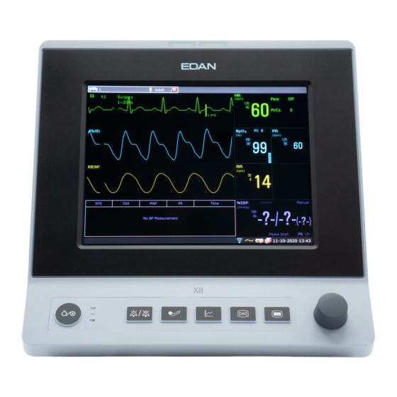
Basic Operation Chapter 3 Basic Operation This manual is for clinical professionals using the X8 X10 and X12 patient monitors. Unless otherwise specified, the information here is valid for all the above products. This user manual describes all features and options. Your monitor may not have all of them; they are not all available in all geographies. -
Page 28: Rear View
Patient Monitor User Manual Basic Operation monitor off. Battery indicator, refer to Section Battery Power Indicator for details. Alternating current indicator Mute —Press it to suspend the output of all audible alarm signals. Upon the configuration, pressing this button to pause or turn off the audio alarm. Further information can be found in the section Audio Alarm Paused and section Audio Alarm Off. -
Page 29: Side View
Patient Monitor User Manual Basic Operation connection. Power cable safety latch. Used to prevent the power cable from loosing or falling. Place the latch on the power cable and press it down firmly to ensure that it secures the power cable. -
Page 30: Operating And Navigating
Patient Monitor User Manual Basic Operation 3.2 Operating and Navigating Everything you need to operate the monitor is contained on its screen. Almost every element on the screen is interactive. Screen elements include measurement data, waveforms, screen keys, information fields, alarms fields and menus. The configurability of the monitor means that often you can access the same element in different ways. -
Page 31: Using Keys
Patient Monitor User Manual Basic Operation Date and time Scroll right to display more shortcut keys Networking symbol Battery status symbol AC power supply symbol Shortcut key area Scroll left to display more shortcut keys Alarm reset key Parameter waveform 3.2.1 Using Keys The monitor has four different types of keys. -
Page 32: Operating Mode
Patient Monitor User Manual Basic Operation Review the trend graph Adjust the screen brightness Review the trend table Zero the IBP sensor Review the alarm event Alarm setup Access the NIBP review Change the beat volume Access the ARR review Enter standby mode Switch to the trend screen Enter night mode... -
Page 33: Standby Mode
Patient Monitor User Manual Basic Operation WARNING Demo Mode is for demonstration purposes only. You must not change into Demo Mode during monitoring. In Demo Mode, all stored trend information is deleted from the monitor’s memory. 3.3.2 Standby Mode To enter into standby mode, select Menu > Common Function > Standby, or press the shortcut on the screen directly, the monitor enters into standby mode after user’s confirmation. -
Page 34: Privacy Mode
Patient Monitor User Manual Basic Operation 3.3.4 Privacy Mode Only if the monitor is connected and admitted by MFM-CMS, the privacy mode can be activated. To enter into privacy mode, you can select Menu > Maintenance > User Maintain > Shortcut Setup >... -
Page 35: Changing Monitor Settings
Patient Monitor User Manual Basic Operation automatically resume the NFC mode. After exiting NFC mode: 1. The HR physiological alarms are still on and can be set to off by the user. 2. Pause Time keeps no change and the user can set it to Permanent. 3. -
Page 36: Adjusting Beat Volume
Patient Monitor User Manual Basic Operation 3.5.3 Adjusting Beat Volume Beat volume is from HR or PR, depending on your setting of the beat source. To change the beat volume: Select the shortcut key on the screen directly, or Select ECG Setup > Beat Volume, then select the appropriate setting for the beat volume: five bars represent the maximum volume and one bar represents the minimum volume. -
Page 37: Disabling The Touch Screen
Patient Monitor User Manual Basic Operation NOTE: If calibration file is lost or damaged, the monitor will automatically enter into screen calibration interface. In the screen calibration interface, the screen turns gray and no measurement data can be displayed. 3.10 Disabling the Touch Screen The user can disable touch screen operation by selecting and holding the permanent key for three seconds. -
Page 38: Chapter 4 Alarms
Patient Monitor User Manual Alarms Chapter 4 Alarms The alarm information here applies to all measurements. Measurement-specific alarm information is discussed in the sections of individual measurements. WARNING A potential hazard can exist if different alarm presets are used for the same or similar equipment in any single area, e.g. - Page 39 Patient Monitor User Manual Alarms 1. High level alarms A high level alarm intensively warns the operator of a high priority alarm condition which requires immediate operator response. Failure to respond to the cause of the alarm condition is likely to result in death or irreversible injury of the patient. 2.
-
Page 40: Controlling Alarm
Patient Monitor User Manual Alarms Alarm Level Prompt Mode is “Di-”, which is triggered once every 30 seconds. When physiological alarm is triggered, the alarm indicator is constantly yellow. While for technical alarm, the alarm indicator is constantly blue. The alarm message flashes with yellow background, and the symbol * is displayed at the alarm area. -
Page 41: Audio Alarm Paused
Patient Monitor User Manual Alarms Upper arrow or lower arrow to increase decrease alarm limit Setting value of high alarm limit Adjustable range Setting value of low alarm limit WARNING When the alarm is set to Off, the monitor won’t give an alarm prompt even if an alarm occurs. -
Page 42: Audio Alarm Off
Patient Monitor User Manual Alarms The monitor displays the audio alarm paused icon The monitor displays the remaining pause time in seconds with red background. When the alarm pause time expires, the audio alarm paused status is automatically terminated and alarm is sounding. -
Page 43: Latching Alarms
Patient Monitor User Manual Alarms 4.5 Latching Alarms To configure the alarm latching setting, select Menu > Maintenance > User Maintain > Alarm Setup and choose Alarm Latch which can be set to On or Off. When it is set to Off, alarm indications end when the alarm condition ends. -
Page 44: Chapter 5 Alarm Information
Patient Monitor User Manual Alarm Information Chapter 5 Alarm Information 5.1 Physiological Alarm Information WARNING Physiological alarms including Asystole, Sustain VT, RESP APNEA, SpO No Pulse, Desat and CO APNEA cannot be turned off. Message Cause Alarm Level HR measuring value is above the upper alarm limit. User-selectable HR High HR measuring value is below the lower alarm limit. - Page 45 Patient Monitor User Manual Alarm Information Message Cause Alarm Level No pace pulse detected in 1.75 times RR interval after a Pacer User-selectable QRS complex. Pacing Adult: RR interval for 5 consecutive QRS complex < 0.5 s. Tachy User-selectable Pediatric/neonatal: RR interval for 5 consecutive QRS complex <...
- Page 46 Patient Monitor User Manual Alarm Information Message Cause Alarm Level The measurement value of Pause/min is greater than Pauses/min User-selectable high alarm limit that has been set. High The measurement value of PVCs is greater than high User-selectable PVCs High alarm limit that has been set.
- Page 47 Patient Monitor User Manual Alarm Information Message Cause Alarm Level PR Low PR measuring value is below lower alarm limit. User-selectable TEMP Measuring value of T1 channel is above upper alarm T1 High User-selectable limit. Measuring value of T1 channel is below lower alarm User-selectable T1 Low limit.
- Page 48 Patient Monitor User Manual Alarm Information Message Cause Alarm Level PA DIA Low PA DIA measuring value is below lower alarm limit. User-selectable PA MAP High PA MAP measuring value is above upper alarm limit. User-selectable PA MAP Low PA MAP measuring value is below lower alarm limit. User-selectable CVP MAP High CVP MAP measuring value is above upper alarm limit.
-
Page 49: Technical Alarm Information
Patient Monitor User Manual Alarm Information Message Cause Alarm Level C.O. TB High TB measuring value is above upper alarm. User-selectable TB Low TB measuring value is below lower alarm. User-selectable 5.2 Technical Alarm Information NOTE: The ECG alarm information listed in the below table describes the electrode names in America. - Page 50 Patient Monitor User Manual Alarm Information Message Cause Alarm Level Action Taken ECG electrode V1 falls off the skin or the ECG cable ECG V1 Lead Off V1 falls off. ECG electrode V2 falls off ECG V2 Lead Off the skin or the ECG cable V2 falls off.
- Page 51 Patient Monitor User Manual Alarm Information Message Cause Alarm Level Action Taken Check whether the RESP leads are well RR cannot be measured due connected. Keep the RESP Noise to patient movement. patient calm better monitoring. Check whether interference to the respiratory signal exists.
- Page 52 Patient Monitor User Manual Alarm Information Message Cause Alarm Level Action Taken Stop using measuring function of SpO module, and module failure High notify biomedical Comm Fail communication failure engineer manufacturer’s service staff. Malfunction in the SpO Replace the SpO sensor or in the extension sensor Sensor Err...
- Page 53 Patient Monitor User Manual Alarm Information Message Cause Alarm Level Action Taken Stop using measuring function of NIBP module, and NIBP module failure High notify biomedical NIBP Comm Fail communication failure engineer manufacturer’s service staff. Check connections and the NIBP pump, valve, cuff or NIBP Leak wrapped cuff to see tube has a leakage.
- Page 54 Patient Monitor User Manual Alarm Information Message Cause Alarm Level Action Taken Check whether the airway is occluded Atmospheric pressure NIBP System or pressure sensor system pressure is abnormal. Pressure works properly. If The valve is occluded so that Abnormality problem still deflation is failed.
- Page 55 Patient Monitor User Manual Alarm Information Message Cause Alarm Level Action Taken Check if the cuff Pulse is too weak, and the NIBP Pulse Signal leak cuff Weak detected signal is too weak. properly wrapped. TEMP Temperature cable of TEMP Make sure that the TEMP T1 Sensor Off channe1 may be disconnected...
- Page 56 Patient Monitor User Manual Alarm Information Message Cause Alarm Level Action Taken Malfunction Replace sensor or in the extension Medium sensor IBP Sensor Err cable. extension cable. Stop measuring YY Comm Fail (YY function stands for the IBP module failure module, and notify label name: Art, PA, High...
- Page 57 Patient Monitor User Manual Alarm Information Message Cause Alarm Level Action Taken concentration EtCO concentration accordingly. EtCO Overrange exceeds measurement High range. Make sure the gas Water trap of SideStream is Occlude High exhaust works well occluded. Others The battery is low, and it at Battery Low Medium least lasts for 20 minutes.
-
Page 58: Prompts
Patient Monitor User Manual Alarm Information Message Cause Alarm Level Action Taken Delete some data in Removable device is Less than 10 M space is left the removable device in the removable device. another full removable device. Repair the removable Removable The removable device is device or replace it... - Page 59 Patient Monitor User Manual Alarm Information Message Cause One of Key ARR alarms is set to Off. Key ARR Alarm Off The electrode has bad contact with patient’s body. Electrode Contact Poor module is analyzing the patient signal and searching for the pulse to compute the saturation, when sensor is Search Pulse connected with patient.
- Page 60 Patient Monitor User Manual Alarm Information Message Cause Enter the IBP zeroing menu, and zeroing is not performed Please Press 'Zero'. yet. Zero OK IBP completes zeroing. During the zeroing process, pressure fluctuation is Pulsatile Pressure Zero Fail. excessive. During the zeroing process, pressure value is beyond the Pressure normal range,Fail.
-
Page 61: Adjustable Range Of Alarm Limits
Patient Monitor User Manual Alarm Information Message Cause If the monitor is not configured with the recorder function, it will indicate Recorder Setup Needed after the Record Recorder Setup Needed button is pressed. No Default Printer No default printer has been set. Incomplete parameter input, In MEWS interface, parameters are not completely input. - Page 62 Patient Monitor User Manual Alarm Information PR alarm limits are listed as follows: unit (bpm) Adjustable Range PR (SpO 30~300 PR (NIBP) 40~240 PR (IBP) 30~300 NIBP alarm limits are listed as follows: unit (mmHg, kPa, cmH O, 1 mmHg = 0.133 kPa, 1 O=1.36 mmHg) Patient Type Adjustable Range (mmHg)
-
Page 63: Chapter 6 Managing Patients
Patient Monitor User Manual Managing Patients Chapter 6 Managing Patients 6.1 Admitting a Patient The monitor displays physiological data and stores it in the trends as soon as a patient is connected. This allows you to monitor a patient who is not yet admitted. It is however important to admit patients properly so that you can identify your patient on recordings, reports, and networked devices. -
Page 64: Quick Admit
Patient Monitor User Manual Managing Patients calculate some measurements, the safety limits that are applied for some measurements, and the alarm limit ranges. The paced setting determines whether the monitor shows pacemaker pulses or not. When Pace is set to Off, pace pulses are filtered and therefore do not show in the ECG wave. WARNING Changing the patient category may change the arrhythmia and NIBP alarm limits. - Page 65 Patient Monitor User Manual Managing Patients The real-time monitoring information is displayed on the central monitoring system as the same to the monitor, and the central monitoring system can perform some bilateral control. For example: changing patient information, receiving patient, discharging patient and so forth.
-
Page 66: Chapter 7 User Interface
Patient Monitor User Manual User Interface Chapter 7 User Interface 7.1 Setting Interface Style The user can set the interface based on the requirement, and the set options include the following: Sweep of the waveform. Parameters needing to be monitored. Changing some settings may have the risk, so only the authorized person can change them. -
Page 67: Viewing Oxycrg Screen
Patient Monitor User Manual User Interface 7.6 Viewing OxyCRG Screen To view the OxyCRG screen, the user can press the shortcut key on the screen directly or select Menu > Display Setup > View Selection > OxyCRG. This interface is always used in NICU because the SpO , HR and Resp of the neonate are different from those of adults. -
Page 68: Viewing The Bed View Window
Patient Monitor User Manual User Interface 7.9 Viewing the Bed View Window The Bed View window allows you to view one waveform, numeric information of all parameters and alarm information from another bed on the same network. The monitor enables a maximum of eight beds to be viewed. -
Page 69: Default Configuration
Patient Monitor User Manual User Interface 7.12 Default Configuration To set default configuration, select Menu > Default. On the Default menu, users can choose a factory configuration (adult, pediatric or neonate) based on the patient category. Also, users can choose a user configuration saved in the monitor if it is available. For more information about user configuration, refer to User Configuration. -
Page 70: Chapter 8 Monitoring Ecg
Patient Monitor User Manual Monitoring ECG Chapter 8 Monitoring ECG 8.1 Overview The electrocardiogram (ECG) measures the electrical activity of the heart and displays it on the monitor as a waveform and a numeric. This chapter also tells you about arrhythmia monitoring and ST monitoring. - Page 71 Patient Monitor User Manual Monitoring ECG WARNING According to AAMI specifications the peak of the synchronized defibrillator discharge should be delivered within 60 ms of the peak of the R wave. The synchronization pulse output on the patient monitors is delayed by a maximum of 35 ms from the R wave peak.
-
Page 72: Ecg Display
Patient Monitor User Manual Monitoring ECG 8.3 ECG Display The figure below is for reference only. ③ ② ① The symbol “①”indicates lead name of display waveform: there are other leads for selection, such as I, II, III, aVR, aVF, aVL, V (for 5 Electrodes). If you want to change the lead, please refer to section Selecting Calculation Lead. -
Page 73: Changing The Ecg Filter Settings
Patient Monitor User Manual Monitoring ECG 8.3.2 Changing the ECG Filter Settings The ECG filter setting defines how ECG waves are smoothed. An abbreviation indicating the filter type is shown underneath the lead label on the monitor display. Filter settings do not affect ST measurement. -
Page 74: Monitoring Procedure
CAUTION To protect the monitor from damage during defibrillation, for accurate ECG information and to protect against noise and other interference, use only ECG electrodes and cables specified by EDAN. 8.5.3 Selecting Electrode Type To change the electrode type, please: 1. -
Page 75: Installing Electrodes
Patient Monitor User Manual Monitoring ECG 8.5.4 Installing Electrodes NOTE: The following table gives the corresponding electrodes names used in Europe and America respectively. (Electrodes names are represented by R, L, F, N, C, C1-C6 in Europe, whose corresponding electrodes names in America are RA, LA, LL, RL, V, V1-V6.) AHA (American Standard) IEC (Europe Standard) - Page 76 Patient Monitor User Manual Monitoring ECG 8.5.4.2 Placement for 5-Electrode Take the American standard for example, see the following figure: ■ RA placement: directly below the clavicle and near the right shoulder. ■ LA placement: directly below the clavicle and near the left shoulder. ■...
- Page 77 Patient Monitor User Manual Monitoring ECG V-Electrode Placement for 5-Electrode 8.5.4.3 Placement for 6-Electrode For the placement of 6 electrodes, please use the position of 5 electrodes in the schematic diagram to remove the two thoracic leads. The two thoracic leads Va and Vb can be placed at any two positions from V1 to V6, as shown in the following thoracic leads.
- Page 78 Patient Monitor User Manual Monitoring ECG 8.5.4.4 Placement for 10-Electrode Take the American standard for example; the 10 electrodes should be placed as follows: The limb electrodes are placed in the same position as the 3 electrodes placement. ■ RL placement: on the right hypogastrium. ■...
-
Page 79: Ecg Menu Setup
Patient Monitor User Manual Monitoring ECG shoulders, the right and left sides near the abdomen, and the chest lead on the left side at mid-chest. Avoid placing the electrodes on the upper arms. Otherwise the ECG waveform will be too small. WARNING ECG cables can be damaged when connected to a patient during defibrillation or using other high frequency equipment. -
Page 80: Smart Lead Off
Patient Monitor User Manual Monitoring ECG will automatically switch to PR as the beat source if: a valid ECG lead can no longer be measured and a PR source is switched on and available. If an ECG lead becomes available again, the monitor automatically uses HR as beat source and the monitor gives a “Di”... -
Page 81: Setting Pace Status
Patient Monitor User Manual Monitoring ECG Electrode button to enable the monitor to perform lead off alarm according to actual electrodes. If AUTO is selected in the ECG Setup menu, Va and Vb cannot be set when the monitor recognizes the 10 electrodes system automatically. Va is fixed as V1 and Vb is fixed as V2. -
Page 82: Ecg Waveform Settings
Select Menu > Maintenance > User Maintain > Other Setups > Activate 6/10 Electrodes in order to get the SN number which is supposed to be supplied to EDAN for a corresponding password. Enter the password on the above-mentioned interface and restart the monitor, and the 6/10 Electrodes monitoring function will be activated. -
Page 83: Waveform Durations And Isoelectric Segments
Patient Monitor User Manual Monitoring ECG The measurement function provides the automatic measurement of the common parameters, such as heart rate, PR interval, QRS duration, QT/QTC interval, P/QRS/T axis, RV5/SV1 amplitude and RV5+SV1 amplitude. The interpretation function provides the automatic analysis of hundreds of abnormal cases, such as arrhythmia, AV block, IVCD (Intraventricular Conduction Block), myocardial infarction, ventricular hypertrophy and atrial enlargement, ST-T abnormality and electrical axis deviation. -
Page 84: Setting St Analysis
Patient Monitor User Manual Monitoring ECG measurement value and ST template can be obtained in different filter modes. If the doctor wants to observe the waveform to evaluate ST segment result, it is recommended to use the ST template for observation, as it is not affected by the filter mode. -
Page 85: About St Measurement Points
Patient Monitor User Manual Monitoring ECG 8.8.3 About ST Measurement Points The ST value for each beat complex is the vertical difference between the ISO point and the ST point, as shown in the diagram below. The isoelectric (ISO) point provides the baseline, and the ST point is at the midpoint of the ST segment. - Page 86 Patient Monitor User Manual Monitoring ECG ARR Alarms Occurring Condition Asystole No QRS is detected for 4 consecutive seconds. 4 consecutive seconds' fibrillation wave occurs; Or 5 consecutive V-Fib/V-Tach ventricular beats, and ventricular HR ≥100 bpm. 3 ≤ the number of consecutive PVCs < 5 Run PVCs Couplet 2 consecutive PVCs...
- Page 87 Patient Monitor User Manual Monitoring ECG ARR Alarms Occurring Condition Acc. Vent 5 consecutive ventricular beats, and 40 bpm ≤ ventricular HR < 100 bpm. Rhythm No QRS is detected within the heartbeat pause threshold value that has Pause been set. Pauses/min The measurement value of Pause/min is greater than high alarm limit that High...
- Page 88 Patient Monitor User Manual Monitoring ECG calls. The ventricular should have a different appearance from “normal heartbeat”. Physicians should be more alert to these patients. Intermittent bundle branch block: bundle branch block or other bundle obstruction phenomenon is a challenge for arrhythmia algorithm. If the QRS wave during the block has a considerable change in morphology compared to the normal QRS of learning, the blocked heartbeat may be misclassified as ventricular tachycardia, resulting in an incorrect chamber alarm.
-
Page 89: Arr Analysis Menu
Patient Monitor User Manual Monitoring ECG 8.9.2 ARR Analysis Menu 8.9.2.1 Switching ARR Analysis On and Off To switch ARR Analysis on or off, in the ECG Setup menu, select ARR Analysis to toggle between On and Off from the popup interface. 8.9.2.2 ARR Alarm Setup Select ECG Setup >... - Page 90 Patient Monitor User Manual Monitoring ECG ARR Alarm Range PAC Trigeminy Pauses/min High 1/min to 20/min Sustain VT 15 s to 45 s ExtremeBrady 15 bpm to 60 bpm Low Voltage(Limb) 0.3 mV to 0.8 mV 8.9.2.4 ARR Selflearning Pick this item ARR Selflearn to start a learning procedure, and ECG ARR Learning displayed on the screen.
-
Page 91: Chapter 9 Monitoring Resp
Patient Monitor User Manual Monitoring RESP Chapter 9 Monitoring RESP 9.1 Overview The monitor measures respiration from the amount of thoracic impedance between two ECG electrodes. The change of impedance between the two electrodes, (due to the thoracic movement), produces a respiratory waveform on the screen. 9.2 RESP Safety Information WARNING If you do not set the Hold High and Hold Low for the respiration correctly in manual... -
Page 92: Electrode Placement For Monitoring Resp
Patient Monitor User Manual Monitoring RESP WARNING When ECG electrode is placed on patient’s limb, the impedance respiration may be unreliable. NOTE: The RESP monitoring is not recommended to be used on patients who are very active, as this can cause false alarms. 9.3 Electrode Placement for Monitoring RESP Correct patient skin preparation techniques for electrode placement are important for RESP measurement: you will find this information in the chapter on ECG. -
Page 93: Selecting Resp Lead
Patient Monitor User Manual Monitoring RESP NOTE: Place the red and green electrodes diagonally to optimize the respiration waveform. Avoid the liver area and the ventricles of the heart in the line between the RESP electrodes so as to avoid cardiac overlay or artifacts from pulsating blood flow. This is particularly important for neonates. -
Page 94: Chapter 10 Monitoring Spo
Use only EDAN permitted sensors and extension cables with the monitor. Other sensors or extension cables may cause improper monitor performance and/or minor personal injury. -
Page 95: Measuring Spo
Patient Monitor User Manual Monitoring SpO waveform is not directly proportional to the pulse volume. The device is calibrated to display functional oxygen saturation. A Functional tester or simulator can not be used to assess the SpO accuracy. However, it can be used to demonstrate that a particular monitor reproduces a calibration curve that has been independently demonstrated to meet a particular accuracy. -
Page 96: Measurement Limitations
Patient Monitor User Manual Monitoring SpO NOTE: Injected dyes such as methylene blue or intravascular dyshemoglobins such as methemoglobin and carboxyhemoglobin may lead to inaccurate measurements. Inspect the sensor to ensure that the light emitter and receiver are aligned with each other and there is no gap between the sensor and the finger. -
Page 97: Assessing The Validity Of A Spo
Patient Monitor User Manual Monitoring SpO Adjacent SpO sensors may interfere with each other (eg, multiple SpO measurements in the same patient). Be sure to cover the sensor with opaque material to reduce cross-interference. Move the sensor to a less active site, and keep the patient still, if possible. 10.5 Assessing the Validity of a SpO Reading You can check the quality of the pleth wave and the stability of the SpO... -
Page 98: Perfusion Index (Pi)
Patient Monitor User Manual Monitoring SpO indication on the monitor. This delay is the combination of the configured alarm delay time plus the general system delay time. 10.7 Perfusion Index (PI)* PI is a numeric value indicating perfusion level. It reflects the perfusion level at the monitoring site. As the measurement of SpO is based on the pulsation caused by the blood flow through the vessel, PI is in relation to the strength of the pulse. -
Page 99: Chapter 11 Monitoring Pr
Patient Monitor User Manual Monitoring PR Chapter 11 Monitoring PR 11.1 Overview The pulse numeric counts the arterial pulsations that result from the mechanical activity of the heart in beats per minute (bpm). You can obtain a pulse from any measured SpO signal or any arterial pressure. -
Page 100: Chapter 12 Monitoring Nibp
Patient Monitor User Manual Monitoring NIBP Chapter 12 Monitoring NIBP 12.1 Overview This monitor uses the oscillometric method for measuring NIBP. It can be used for adult, pediatric and neonatal patients. It is also intended for use with pregnant, including pre-eclamptic patients. -
Page 101: Measurement Limitations
Patient Monitor User Manual Monitoring NIBP WARNING Verifying the calibration is only applicable for adults, and it cannot be operated in automatic measuring interval. Continuous measuring cannot be operated in automatic measuring interval either. NOTE: It is suggested that the user should not start NIBP measuring when the low battery displays, or the monitor may be turned off automatically. -
Page 102: Measurement Methods
Patient Monitor User Manual Monitoring NIBP 12.4 Measurement Methods There are three methods of measuring NIBP: Manual - measurement on demand. Auto - continually repeated measurements (between 1 and 480 minute adjustable interval). After the first measurement starts manually, the monitor will automatically measure NIBP as preset interval. -
Page 103: Operation Prompts
Patient Monitor User Manual Monitoring NIBP discoloration and eventual ischemia of the extremity. 3. Check whether the patient type is appropriately selected. Access the Patient Setup menu from Menu. Turn the knob to select the required patient Type in the Patient Info. menu. 4. -
Page 104: Correcting The Measurement If Limb Is Not At Heart Level
Patient Monitor User Manual Monitoring NIBP 4. Stopping continuous measurement During continuous measurement, press the button on the front panel or shortcut key on the screen at any time to stop continuous measurement. 12.5.2 Correcting the Measurement if Limb is not at Heart Level To correct the measurement if the limb is not at heart level to the displayed value: Add 0.75 mmHg (0.10 kPa) for each Deduct 0.75 mmHg (0.10 kPa) for each... -
Page 105: Setting Inflation Mode
Patient Monitor User Manual Monitoring NIBP 2. Wrap the cuff around the cylinder of an appropriate size, don’t wrap the cuff around limbs. 3. Make sure the patient type has been set to Adult. 4. Access User Maintain > NIBP Maintain. 5. -
Page 106: Chapter 13 Monitoring Temp
Patient Monitor User Manual Monitoring TEMP Chapter 13 Monitoring TEMP 13.1 Overview Body temperature is measured by means of a thermistor probe (a semiconductor whose resistance changes with temperature) that is applied to the skin or to the rectum. Two TEMP probes can be used simultaneously to measure two TEMP values and get the temperature difference. -
Page 107: Chapter 14 Monitoring Ibp
Patient Monitor User Manual Monitoring IBP Chapter 14 Monitoring IBP 14.1 Overview IBP is measured by means of a catheter inserted directly into the circulatory system. A pressure transducer connected to the catheter converts the mechanical force exerted by the blood into an electrical signal, which is displayed graphically as pressure versus time on a monitor screen or numerically on digital display. -
Page 108: Selecting A Pressure For Monitoring
Patient Monitor User Manual Monitoring IBP 1. Plug the pressure cable into the corresponding socket and switch on the monitor. 2. Prepare the flush solution. 3. Flush through the system, exhaust all air from the tube, and ensure that the transducer and stopcocks are free of air bubbles. -
Page 109: Troubleshooting The Pressure Zeroing (Taking Art For Example)
Patient Monitor User Manual Monitoring IBP Every time you reconnect the transducer cable to the monitor; If you think the monitor’s pressure readings are not correct. When using a pressure module, the zero information is stored in the module. The zeroing procedure is listed as below: 1. -
Page 110: Measuring Pawp
Patient Monitor User Manual Monitoring IBP Select Menu > Maintenance > User Maintain > Other Setups, and set IBP Wave Overlapping to On or Off. Click the IBP waveform area to show the IBP Wave Setup menu. Select Add IBP Waves and then select the IBP waves for overlapping from the pop-up list. A maximum of four overlapping waveforms can be displayed. -
Page 111: Calculating Cpp
Patient Monitor User Manual Monitoring IBP WARNING Prolonged inflation can cause pulmonary hemorrhage, infarction or both. Inflate the balloon for the minimum time necessary to get an accurate measurement. If the PAWP (mean) is greater than the PA (systolic), deflate the balloon and report the incident in accordance with hospital policy, because the pulmonary artery could be accidently ruptured, and the PAWP value derived will not reflect the patient’s hemodynamic state, but will merely reflect the pressure in the catheter or balloon. - Page 112 Patient Monitor User Manual Monitoring IBP WARNING The clinical value of the derived PPV information must be determined by a physician. According to recent scientific literature, the PPV information is restricted to sedated patients who receive controlled mechanical ventilation and without arrhythmia. Whether the calculation results in other situations are clinically significant, applicable and reliable must be determined by a physician.
-
Page 113: Chapter 15 Monitoring Co
Monitoring CO Chapter 15 Monitoring CO 15.1 Overview The monitor provides the sidestream and mainstream methods for CO monitoring. EDAN EtCO module is used for sidestream measuring. The principle of CO measurement is primarily based on the fact that CO molecule can absorb 4.3μm infrared ray. -
Page 114: Monitoring Procedures
30 days. 15.3 Monitoring Procedures 15.3.1 Zeroing the Sensor EDAN EtCO module itself has automatic zero function, only when the measurement is abnormal or measurement results are doubtful, the user can perform manual zero as following steps: 1. - Page 115 When replacing the water trap or suspecting the measurement value, please check if the O-rings of the water trap holder are normal and well installed. If the O-rings get damaged or loose, contact EDAN’s service staff. To prevent the module from abnormal work, please ensure the water trap detection button is not mistakenly touched.
-
Page 116: Setting Co 2 Corrections
Patient Monitor User Manual Monitoring CO CAUTION The sample gas flowrate 50 ml/min is only applicable to patients whose respiratory rate ranges from 0 rpm to 40 rpm. NOTE: Disconnect the water trap from the holder or set Work Mode to Standby when the module is not in use. -
Page 117: Setting Co Waveform
Patient Monitor User Manual Monitoring CO WARNING Safety and effectiveness of the respiration measurement method in the detection of apnea, particularly the apnea of prematurity and apnea of infancy, has not been established. 15.6 Setting CO Waveform Open the menu CO Waveform Setup by clicking on the CO waveform area: ... -
Page 118: Chapter 16 Monitoring C.o
Patient Monitor User Manual Monitoring C.O. Chapter 16 Monitoring C.O. 16.1 Overview The cardiac output (C.O.) measurement invasively measures cardiac output and other hemodynamic parameters by using the Thermodilution method. The Thermodilution method is to inject a cold solution into the blood circulation system and measure the temperature changes caused by the cold solution through the thermistor of the pulmonary artery floating catheter, and the C.O. - Page 119 Patient Monitor User Manual Monitoring C.O. 1: Monitor; 2: Thermodilution Catheter; 3: Cardiac Output Cable; 4: Injectate Sensor Housing; 5: Injectate; 6: Delivery System; 7: In-line injectate Temperature probe. C.O. Sensor Connection 3. Open the patient information window to confirm the patients’ height and weight. 4.
- Page 120 Patient Monitor User Manual Monitoring C.O. Measurement curve X axis: Change the Scale X (time) value. Two modes are available: 0 s to 30 s, 0 s to 60 s. If you Cardiac Output start measurement in the 0 s to 30 s mode, it will Cardiac Index be switched to 0 s to 60 s mode automatically if the measurement cannot finish within 30 seconds.
- Page 121 Patient Monitor User Manual Monitoring C.O. the parameter area and the start measurement time (7 in the above figure). To ensure the accuracy of the measurement, it is suggested that a reasonable interval should take place between two consecutive measurements. The length of the interval can be set in the C.O. Setup menu (Time unit: second).
-
Page 122: Blood Temperature Monitoring
Patient Monitor User Manual Monitoring C.O. NOTE: The blood temperature alarm will not function during C.O. measurement. It will resume automatically when the measurement is over. It is strongly recommended that the user must push the injector within four seconds after pressing the Start button. -
Page 123: Chapter 17 Freeze
Patient Monitor User Manual Freeze Chapter 17 Freeze 17.1 Overview When monitoring a patient, the user may freeze the waveforms and examine them. Generally, the user can review a frozen waveform of a maximum of 120 seconds. The freeze function of this monitor has the following features: ... -
Page 124: Chapter 18 Review
Patient Monitor User Manual Review Chapter 18 Review The monitor provides 120-hour trend data of all parameters, storage of 1200 NIBP measurement results, 200 alarm events, 200 arrhythmia events, and 50 sets of 12-lead analysis results. This chapter gives detailed instruction for review of all data. 18.1 Trend Graph Review To review the trend graph, please press the Trend Graph key on the screen or select... -
Page 125: Trend Table Review
Patient Monitor User Manual Review Select beside the parameter name and choose the desired parameter from the pop-up list (as shown in red circle above). Press the symbols to switch parameters in batch. ■ Select Zoom to adjust the trend scale. Once the trend scale on the trend graph review interface is adjusted, the trend scale of the corresponding parameter in TrendScreen of the main interface will also change. -
Page 126: Alarm Review
Patient Monitor User Manual Review ■ Select to browse more NIBP measurement data. ■ Select Record to print out the NIBP measurement data by the recorder. ■ Select Print to print out the NIBP review report by the printer. 18.4 Alarm Review To review the alarm event, please press the Alarm Review key on the screen or select Menu >... -
Page 127: 12-Lead Analysis Review
Patient Monitor User Manual Review NOTE: If there are more than 200 arrhythmia events, the monitor will only keep the recent ones. The name of arrhythmia event will be shown on the alarm status area. The renaming is only available for the ARR alarm event of the current patient, not for that of the history patient. -
Page 128: Chapter 19 Calculation And Titration Table
WARNING The correctness of the input parameters and the suitability of the calculated results should be carefully verified. EDAN is not liable for any consequences arising from input or operation errors. 19.1 Drug Calculation 19.1.1 Calculation Procedures The drug calculation window is displayed by selecting Menu >... -
Page 129: Calculation Unit
Patient Monitor User Manual Calculation and Titration Table The system generates values that can’t be treated the calculation results. The user must enter the correct parameter value based on the doctor’s instruction. Manually enter the value of patient weight or directly obtain the value from the monitor by selecting Get Info. -
Page 130: Hemodynamic Calculation
Patient Monitor User Manual Calculation and Titration Table Dose Type The data in the titration table will vary with the changes above. And the user can perform the following: Select to observe more data. Record the data displayed in the current window by selecting Record. 19.2 Hemodynamic Calculation 19.2.1 Calculation Procedure The hemodynamic calculation interface is displayed by selecting Menu >... -
Page 131: Oxygenation Calculation
Patient Monitor User Manual Calculation and Titration Table Items English Full Name/Description SVRI Systemic vascular resistance index Pulmonary vascular resistance PVRI Pulmonary vascular resistance index Left cardiac work LCWI Left cardiac work index Right cardiac work RCWI Right cardiac work index LVSW Left ventricular stroke work LVSWI... -
Page 132: Output Parameters
Patient Monitor User Manual Calculation and Titration Table Items English Full Name/Description Oxygen consumption Respiratory quotient ATMP Atmospheric pressure Height Weight 19.3.3 Output Parameters Items English Full Name/Description Body surface area calc Calculated oxygen consumption C (a-v) O Arterial venous oxygen content difference Oxygen extraction ratio Oxygen transport Partial pressure of oxygen in the alveoli... -
Page 133: Input Parameters
Patient Monitor User Manual Calculation and Titration Table 19.4.2 Input Parameters Items English Full Name/Description Percentage fraction of inspired oxygen Respiration rate PeCO Partial pressure of mixed expiratory CO PaCO Partial pressure of carbon dioxide in the arteries Partial pressure of oxygen in the arteries Tidal volume Respiratory quotient ATMP... -
Page 134: Input Parameters
Patient Monitor User Manual Calculation and Titration Table 19.5.2 Input Parameters Items English Full Name/Description Urine potassium URNa Urinary sodium Urine Urine Posm Plasm osmolality Uosm Urine osmolality SerNa Serum sodium Serum creatinine Urine creatinine Blood urea nitrogen Urine urea nitrogen Height Weight Type... -
Page 135: Chapter 20 Recording
Patient Monitor User Manual Recording Chapter 20 Recording A thermal dot matrix recorder is used for the monitor and can support many recording types and output patient information, measurement data, review data waveform and so forth. Recording indicator Paper feeding key: press this key to start or stop feeding recording paper without outputting anything on the paper Paper outlet Recorder door... - Page 136 Patient Monitor User Manual Recording Recording Type Description/ Procedure Continual real-time recording Select at least one Rec waveform in Recorder Setup (A maximum of three waveforms can be selected), select Continual in R-T Rec Time. Press shortcut key on the screen to start the recording. Press the shortcut again to stop recording.
-
Page 137: Recorder Operations And Status Messages
Patient Monitor User Manual Recording Recording Type Description/ Procedure 12-lead analysis recording Select ECG Setup > 12-L Review, click Record to start recording. C.O. measurement recording Select C.O. Option > C.O. Measure, click Record to start recording. Frozen waveform recording In the Freeze window, click Record to start recording. -
Page 138: Removing Paper Jam
Patient Monitor User Manual Recording 2. Insert a new roll of paper into the paper cassette, printing side facing upwards. 3. Ensure proper position and tidy margin. 4. Pull about 2 cm of the paper out, and close the recorder casing. NOTE: Be careful when inserting papers. - Page 139 Patient Monitor User Manual Recording for a paper jam. Remove the paper jam in the following way: ■ Cut the record paper from the feeding edge. ■ Open the recorder casing. ■ Re-insert the paper. NOTE: If the monitor is not configured with the recorder function, it will indicate Recorder Setup Needed after is pressed.
-
Page 140: Chapter 21 Printing Patient Reports
Patient Monitor User Manual Printing Patient Reports Chapter 21 Printing Patient Reports Patient reports can be printed out by an HP series laser printer connected with the monitor. NOTE: Use the printer HP Laser Jet P2055dn which is tested to be compatible with the monitor. 21.1 Printer Settings You can configure the printer settings on the monitor before printing out patient reports. - Page 141 Patient Monitor User Manual Printing Patient Reports Report Type Procedure 12-lead analysis waveform In the 12-Lead Diagnosis Waveform Review window, report click Print to start printing. Drug calculation titration report In the Titration window, click Print to start printing. Oxygenation calculation report In the Oxygenation window, click Print to start printing.
-
Page 142: Chapter 22 Other Functions
Patient Monitor User Manual Other Functions Chapter 22 Other Functions 22.1 Nurse Call The monitor provides dedicated nurse call port which is connected to nurse call system through the nurse call cable to perform the nurse call function. You should activate the function following the steps below: Select Menu >... -
Page 143: Storing Data In The Storage Device
Wi-Fi again. Then retry to connect to a wireless network. If the wireless network still fails to be connected, please try to restart the monitor and connect again. Use the wireless device recommended by EDAN, otherwise some exceptional situations such as frequent network disconnection may occur on the monitor. -
Page 144: Selecting A Storage Device
CAUTION Not all the removable devices are compatible with the monitor, Use the removable devices recommended by EDAN. Do not set the read-only switch on the removable device to on when the removable device is inserted in the monitor. -
Page 145: Exporting Data Stored In The Internal Storage Device
Patient Monitor User Manual Other Functions History Patient, and then click Delete data on the Review menu. Further confirmation of deletion is required. To delete data of all patients, select Menu > Review > History Patient and click Delete all data on the History Patient Review menu. -
Page 146: Mews Score Interface
Patient Monitor User Manual Other Functions NOTE: The MEWS score results are for reference only and the score significance must be determined by the physician. 22.5.1 MEWS Score Interface There are three methods as following to enter into MEWS score system interface: 1. -
Page 147: Mews Score Result
Patient Monitor User Manual Other Functions Consciousness. After clicking Start to Score, the monitor will display MEWS result that will be refreshed with the same interval as NIBP measurements. Clicking Stop Scoring could exit MEWS score. 22.5.4 MEWS Score Result MEWS results include MEWS, time and severity level. -
Page 148: Chapter 23 Using Battery
Patient Monitor User Manual Using Battery Chapter 23 Using Battery This monitor can run on battery power, which ensures its uninterrupted operation even when AC power supply is interrupted. The battery recharges whenever the monitor is connected to the AC power source. -
Page 149: Battery Power Indicator
Patient Monitor User Manual Using Battery 23.2 Battery Power Indicator The indicator labeled Battery on the front panel of the monitor illuminates in green when the monitor is battery powered and illuminates in yellow when battery is being charged. The indicator is not illuminated when the monitor is not powered or fully powered, or when AC power is applied. -
Page 150: Maintaining The Battery
Patient Monitor User Manual Using Battery 23.6 Maintaining the Battery Batteries should be conditioned regularly to maintain their useful life. Remove the batteries from the monitor if they are not used for a longer period of time. And recharge the batteries at a minimum of every 6 months when they are stored. Discharge the battery completely once every month. -
Page 151: Chapter 24 Care And Cleaning
Patient Monitor User Manual Care and Cleaning Chapter 24 Care and Cleaning Use only the EDAN-approved substances and methods listed in this chapter to clean or disinfect your equipment. Warranty does not cover damage caused by using unapproved substances or methods. -
Page 152: Cleaning The Monitor
Patient Monitor User Manual Care and Cleaning 24.2.1 Cleaning the Monitor WARNING Before cleaning the monitor, make sure that the monitor is switched off and disconnected from the power line. To surface-clean the monitor, follow these steps: Switch off the monitor and disconnect it from the power line. Wipe the entire exterior surface, including the screen, of the equipment using a soft cloth dampened with the cleaning solution thoroughly until no visible contaminants remain. -
Page 153: Disinfection
Patient Monitor User Manual Care and Cleaning Thread the hose from within the cuff and out through the small hole at the top of the cuff. Adjust the bladder until it is in position. 24.2.2.3 Cleaning the SpO Sensor Wipe the surfaces of the sensor and cable using a soft cloth dampened with the cleaning solution until no visible contaminants remain. -
Page 154: Disinfecting The Monitor
Patient Monitor User Manual Care and Cleaning WARNING The monitor and reusable accessories shall be disinfected to avoid patient cross infection. CAUTION Do not use any disinfectant containing additional active ingredients other than those listed, such as disinfectant didecyl dimethyl ammonium bromide which contains quanternary ammonium salt. -
Page 155: Cleaning And Disinfecting Other Accessories
Patient Monitor User Manual Care and Cleaning Wipe the cuff and the air bladder with a soft cloth dampened with the disinfectant solution. Leave the cuff and air bladder to air dry for at least 30 minutes. Replacing the Air Bladder: After disinfection, replace the air bladder into the cuff. -
Page 156: Chapter 25 Maintenance
Maintenance shall be carried out at least once every two years, or as specified by local regulations. The following tasks are for EDAN-qualified service professionals only. Contact an EDAN-qualified service provider if your monitor needs a safety or performance test. Clean and disinfect equipment to decontaminate it before testing or maintaining it. -
Page 157: Chapter 26 Warranty And Service
EDAN will, at its discretion, repair or replace the defective part(s) free of charge. EDAN will not provide a substitute product for use when the defective product is being repaired. -
Page 158: Chapter 27 Accessories
Patient Monitor User Manual Accessories Chapter 27 Accessories You can order accessories from EDAN supplies at www.edan.com.cn or consult your local EDAN representative for details. WARNING Never reuse disposable transducers, sensors, accessories and so forth that are intended for single use, or single patient use only. Reuse may compromise device functionality and system performance and cause a potential hazard. - Page 159 Patient Monitor User Manual Accessories Part Number Accessories 01.57.471228 5-lead, 12-pin, Defib-proof, Adult/pediatric 01.57.471229 5-lead, 12-pin, Defib-proof, Adult/pediatric, Extended 01.13.036620 5-lead, Clip, AHA, Adult/pediatric, Extended 01.13.036621 5-lead, Clip, AHA, Adult/pediatric 01.13.036622 5-lead, Snap, AHA, Adult/pediatric, Extended 01.13.036623 5-lead, Snap, AHA, Adult/pediatric 01.13.036624 5-lead, Clip, IEC, Adult/pediatric, Extended 01.13.036625...
- Page 160 Patient Monitor User Manual Accessories Part Number Accessories 01.57.471465 5-lead, 12-pin, Defib-proof, Clip, IEC, 3.4 m, Reusable 01.57.471466 5-lead, 12-pin, Defib-proof, Clip, AHA, 3.4 m, Reusable 01.57.471467 5-lead, 12-pin, Defib-proof, Snap, IEC, 3.4 m, Reusable 01.57.471468 5-lead, 12-pin, Defib-proof, Snap, AHA, 3.4 m, Reusable 01.57.471473 5-lead, 12-pin, ESU-proof, Clip, IEC, 3.4 m, Reusable 01.57.471474...
-
Page 161: Spo 2 Accessories
Patient Monitor User Manual Accessories Part Number Accessories 01.57.472014 Disposable ECG Electrodes 01.57.471276 Disposable ECG Electrodes Disposable ECG Electrodes 01.57.471056 Disposable ECG Electrodes 01.57.471057 Disposable ECG Electrodes 01.57.471060 27.2 SpO Accessories Part Number Accessories 02.57.225029 7-pin SH1 Adult Reusable SpO Sensor /adult, 2.5 m 02.01.210120 SH1 Adult Reusable SpO... -
Page 162: Temp Accessories
Patient Monitor User Manual Accessories Part Number Accessories 01.57.471330 NIBP Cuff, E9, Adult, 27-35 cm, reusable 01.57.471331 NIBP Cuff, E10, Large adult, 34-43 cm, reusable 01.57.471396 NIBP Cuff, E11,Thigh, 42-54 cm, reusable 01.57.471323 NIBP Cuff, Neonate, 10 cm-15 cm, reusable 01.57.471324 NIBP Cuff, Neonate, 6 cm-11 cm, reusable 01.57.471157... -
Page 163: Accessories
Patient Monitor User Manual Accessories Part Number Accessories 01.57.471173 IBP Pressure transducer interface cable/Hospira type interface 01.57.471166 IBP Pressure transducer interface cable/the UTAH type interface 01.57.471836 IBP Pressure transducer interface cable/12 pin,B.Braun type interface 01.57.471971 12 pin, dual channel, IBP cable (BD) 01.57.471972 12 pin, dual channel, IBP cable (EDWARD) 01.57.471973... -
Page 164: Accessories
01.13.037122 Power cable, length 1.8 m, American standard, medical grade 01.57.078035 Recorder paper 01.23.068023 Linear Barcode Scanner 02.04.241690 Patient monitor mounting arm assembly kit (X8/X10, big basket) 02.04.101976 Rolling Stand Basket (in the bottom) 02.04.241699 Patient monitor mounting arm assembly kit (M3/iM50) 83.60.261069 MT-206 Trolley (Metal wheels, X8/X10) - Page 165 Patient Monitor User Manual Accessories Part Number Accessories 01.21.064381 Rechargeable Lithium-Ion Battery, 5100 mAh, 10.8 V 02.01.211226 Patient monitor mounting arm assembly kit 02.01.211225 Patient monitor mounting arm assembly kit 02.04.241697 Patient monitor mounting arm assembly kit (iM60/iM70) 02.04.241688 Patient monitor mounting arm assembly kit (X12, with basket) 02.01.211227 Trolley adapter assembly kit (X12) 02.04.101984 M3 Trolley Adaptor Kit 83.60.261083 MT-206 Trolley (Metal wheels, X12)
-
Page 166: A Product Specification
Patient Monitor User Manual Product Specification A Product Specification NOTE: The performance of the equipment with ☆ mark is determined to be essential performance. A.1 Classification Anti-electroshock type Class I equipment and internal powered equipment Anti-electroshock degree Ingress Protection IPX1 Disinfection/sterilization method Refer to Chapter Care and Cleaning for details. -
Page 167: Environment Specification
Patient Monitor User Manual Product Specification A.2.3 Environment Specification The monitor may not meet the performance specifications given here if stored or used outside the specified temperature and humidity ranges. When the monitor and related products have differing environmental specifications, the effective range for the combined products is that range which is common to the specifications for all products. -
Page 168: Battery Specification
Patient Monitor User Manual Product Specification A.2.5 Battery Specification ≥ 4 h Operating Time 2550 mAh (standard) ≥ 8 h 5100 mAh (optional) At 20 C ~30 C, with (a) new fully charged battery/batteries, Condition continuous SpO measurement and NIBP automatic measurement mode at interval of 15 minutes, brightness set to “1”. -
Page 169: Wi-Fi (Optional)
Patient Monitor User Manual Product Specification NIBP Measurement Review 1200 sets Arrhythmia events Up to 200 sets 12-lead analysis Review Up to 50 sets Refer to Chapter 18 Review for more information about data review. Data Storage A single piece of patient data maximally contains the following information: Trend graph and trend table 240 hours, resolution: 1 min NIBP measurement review... -
Page 170: Ecg
Patient Monitor User Manual Product Specification A.4 ECG Complies with IEC 60601-2-25: 2011, IEC 60601-2-27: 2011. Lead Mode 3-Electrode: I, II, III 5-Electrode: I, II, III, aVR, aVL, aVF, V 6-Electrode: I, II, III, aVR, aVL, aVF, and leads responding to Va 10-Electrode: I, II, III, aVR, aVL, aVF, V1, V2, V3, V4, V5, V6 Electrode Standard AHA, IEC... - Page 171 Patient Monitor User Manual Product Specification Auxiliary Current (Leads Active electrode: < 100 nA off detection) Reference electrode: < 900 nA ☆ Recovery Time After < 5 s (measured without electrodes as IEC60601-2-27:2011, Sect. 201.8.5.5.1 requires.) Defibrillation Leakage Current of Patient < 10 μA Scale Signal 1 mV PP, accuracy is ±...
- Page 172 Patient Monitor User Manual Product Specification Pace Pulse ☆Pulse Indicator Pulse is marked if the requirements of IEC 60601-2-27: 2011, Sect. 201.12.1.101.12 are met: Amplitude: ± 2 mV to ± 700 mV Width: 0.1 ms to2.0 ms Ascending time: 10 μs to 100 μs ☆Pulse Rejection Pulse is rejected if the requirements of IEC 60601-2-27: 2011, Sect.
- Page 173 Patient Monitor User Manual Product Specification Accuracy -0.8 mV to +0.8 mV: ± 0.02 mV or 10%, whichever is greater. Beyond this range: not specified. Resolution 0.01 mV HR Averaging Method Method 1 Heart rate is computed by excluding the minimum and maximum values from the 12 most recent RR intervals and averaging the residual 10 RR intervals.
-
Page 174: Resp
Patient Monitor User Manual Product Specification Accuracy of Heart Rate Complied with IEC 60601-2-27: 2011, Sect. 201.7.9.2.9.101 b) Meter and Response to 4), the HR value after 20 seconds of stabilization is displayed as Irregular Rhythm follows: Ventricular bigeminy: 80 bpm± 1 bpm Slow alternating ventricular bigeminy: 60 bpm±... -
Page 175: Nibp
Patient Monitor User Manual Product Specification Within the baseline impedance range: 0.3 Ω Measuring Sensitivity Waveform Bandwidth 0.2 Hz to 2.5 Hz (-3 dB) Sinusoid, 45.6 kHz( 10%), < 350 μA Respiration Excitation Waveform ☆RR Measuring Range ☆Adult 0 rpm to120 rpm ☆Neo/Ped 0 rpm to150 rpm Resolution... -
Page 176: Spo
Patient Monitor User Manual Product Specification ☆Neonatal Mode SYS: 25 mmHg to 140 mmHg DIA: 10 mmHg to 115 mmHg MAP: 15 mmHg to 125 mmHg ☆Alarm Type SYS, DIA, MAP, PR(NIBP) ☆ Cuff 0 mmHg to 300 mmHg Pressure Measuring Range Pressure Resolution... -
Page 177: Temp
Thermal resistance Position Skin, oral cavity, rectum Measure Parameter T1, T2, TD(the absolute value of T2 minus T1) Channel X8:1 X10/X12:2 Sensor Type YSI-10K and YSI-2.252K C, F Unit 0 C to 50 C(32 º F to 122 º F) Measuring Range 0.1 C (0.1 º... -
Page 178: Ibp
Patient Monitor User Manual Product Specification A.9 PR Measuring range Accuracy Resolution 25 bpm to 300 bpm 2 bpm PR (SpO 1 bpm PR (NIBP) 40 bpm to 240 bpm ± 3 bpm or 3.5%, whichever is greater 1 bpm 20 bpm to 300 bpm 30 bpm to 300 bpm: ... - Page 179 Patient Monitor User Manual Product Specification A.11 CO Complies with ISO 80601-2-55: 2011. Intended Adult, pediatric, neonatal Patient Measure EtCO , FiCO , AwRR Parameters Unit mmHg, %, kPa 0 mmHg to 150 mmHg (0 % to 20%) ☆ Measuring Range AwRR 2 rpm to 150 rpm EtCO...
- Page 180 Patient Monitor User Manual Product Specification Time < 4 s (with 2 m gas sampling tube, sample gas flowrate: 70 ml/min) Work Mode Standby, measure Range: 0% to 100% Resolution: 1% Compensation Default: 16% Range: 0% to 100% Resolution: 1% Compensation Default: 0% Range: 0% to 20%...
-
Page 181: C.o
Patient Monitor User Manual Product Specification Interfering Gas Effects: Gas Level (%) Quantitative Effect/Comments Nitrous oxide The interfering gas will have no effect on the measurement value if compensation of O Halothane anesthetic agents has been correctly set. Enflurane Isoflurane Sevoflurane Desflurane NOTE:... -
Page 182: Interfaces
Patient Monitor User Manual Product Specification A.13 Interfaces A.13.1 Analog Output (Optional) Diagnosis/Monitor: 0.5 Hz to 40 Hz Bandwidth (-3 dB; reference Diagnosis 1: 0.05 Hz to 40 Hz frequency: 10 Hz) Surgery: 1 Hz to 20 Hz Enhanced: 2 Hz ~18 Hz Customized: When Low-pass Filter <... -
Page 183: Nurse Call (Optional)
Patient Monitor User Manual Product Specification Minimum Required R-wave 0.3 mV Amplitude Pulse Width 100 ms± 10% Limited Current 15 mA rating Rising and Falling Time < 1 ms Interface Type PS2 connector A.13.3 Nurse Call (Optional) Drive Mode Voltage output ≤... -
Page 184: Vga Interface (Optional)
Patient Monitor User Manual Product Specification A.13.5 VGA Interface (Optional) Number of VGA Interface Horizontal Refreshing Rate (30-94) KHZ Video Signal 0.7 Vpp @ 75 Ohm, HSYNC/VSYNC signal TTL Interface Type DB-15 female receptacle A.13.6 Wired Network Interface Specification 100-Base TX (IEEE802.3) Interface Type Standard RJ-45 network interface - 171 -... -
Page 185: B Emc Information
Guidance and manufacture’s declaration – electromagnetic immunity X8 X10 and X12 are intended for use in the electromagnetic environment specified below. The customer or the user of X8 X10 and X12 should assure that they are used in such an environment. - Page 186 135° , 180° , 225° , on power supply hospital environment. If 315° 270° and 315° input lines the user of X8 X10 and X12 requires continued IEC/EN 0 % U ; 1 cycle 0 % U ; 1 cycle...
-
Page 187: Electromagnetic Immunity
Guidance and manufacture’s declaration – electromagnetic immunity X8 X10 and X12 are intended for use in the electromagnetic environment specified below. The customer or the user of X8 X10 and X12 should assure that they are used in such an environment. - Page 188 RF transmitters, an electromagnetic site survey should be considered. If the measured field strength in the location in which X8 X10 and X12 are used exceeds the applicable RF compliance level above, X8 X10 and X12 should be observed to verify normal operation.
- Page 189 Patient Monitor User Manual EMC Information Table 1 Test specifications for ENCLOSURE PORT IMMUNITY to RF wireless communications equipment Test Band Service Modulation Maximum Distance Immuni frequenc (MHz) power ty test y (MHz) level (V/m) Pulse 380-390 TETRA 400 modulation 18 Hz ±...
-
Page 190: Recommended Separation Distances
RF communications equipment and X8 X10 and X12 X8 X10 and X12 are intended for use in an electromagnetic environment in which radiated RF disturbances are controlled. The customer or the user of X8 X10 and X12 can help prevent... -
Page 191: C Default Settings
Patient Monitor User Manual Default Settings C Default Settings This appendix documents the most important default settings of your monitor as it is delivered from the factory. Note: If your monitor has been preconfigured according to your requirements, the settings at delivery will be different from the default settings listed here. - Page 192 Patient Monitor User Manual Default Settings ExtremeTachy ExtremeBrady Pace Electrode Type 5 Electrodes Screen Layout Normal Filter Monitor Smart Lead Off Heart Volume ST Analysis ST Analysis Alarm Switch Alarm Level Medium Alarm Record Alarm High Limit (ST-X) Alarm Low Limit -0.2 (ST-X) X stands for I, II, III, aVR, aVL, aVF, V, V1, V2, V3, V4, V5 or V6.
-
Page 193: Resp Default Settings
Patient Monitor User Manual Default Settings Tachy Medium Brady Medium Missed Beat Irr Rhythm Pacer not Capture Medium Pacer not Pacing Medium Vent Brady High (non-adjustable) Vent Rhythm Medium Sustain VT On (non-adjustable) High (non-adjustable) ExtremeTachy High (non-adjustable) ExtremeBrady High (non-adjustable) V-Tach High (non-adjustable) Wide QRS Tachy... -
Page 194: Spo 2 Default Settings
Patient Monitor User Manual Default Settings Alarm Low Limit Apnea Alarm Time 20 s Calculation Type Auto Resp Type Sweep 12.5 mm/s Amplitude C.5 SpO Default Settings Settings Alarm Switch Alarm Record Alarm Level Medium Alarm High Limit Alarm Low Limit Pitch Tone Sweep 12.5 mm/s... -
Page 195: Nibp Default Settings
Patient Monitor User Manual Default Settings C.7 NIBP Default Settings NIBP Settings Alarm Switch Alarm Record Alarm Level Medium Alarm High Limit (SYS) Alarm Low Limit (SYS) Alarm High Limit (Map) Alarm Low Limit (Map) Alarm High Limit (DIA) Alarm Low Limit (DIA) Inflation value Unit mmHg... -
Page 196: Co Default Settings
Patient Monitor User Manual Default Settings Alarm Level Medium Unit mmHg Filter 12.5 Hz SYS, DIA, MAP SYS, DIA, MAP SYS, DIA, MAP Alarm High Limit (ART, 160, 90, 110 120, 70, 90 90, 60, 70 P1, P2) Alarm Low Limit (ART, 90, 50, 70 70, 40, 50 55, 20, 35... -
Page 197: C.o. Default Settings
Patient Monitor User Manual Default Settings Alarm Low Limit (AwRR) Sweep 6.25 mm/s Amplitude C.11 C.O. Default Settings C.O. Settings Alarm Switch Alarm Record Alarm Level Medium Alarm High Limit (TB) 40.0 Alarm Low Limit (TB) 30.0 Injective Temperature Auto Source C Temperature Unit... -
Page 198: D Abbreviations
Patient Monitor User Manual Abbreviation D Abbreviations Abbr English Full Name/Description Alternating current Acc. Vent Rhythm Accelerated idioventricular rhythm Adult Afib Atrial fibrillation Anaesthesia gas Arterial Left foot augmented electrode Left arm augmented electrode Right arm augmented electrode AwRR Airway respiration rate Burst count Bispectral index Blood pressure... - Page 199 Patient Monitor User Manual Abbreviation Abbr English Full Name/Description Electromagnetic compatibility Electromyelogram Electromagnetic interference Enflurane Emergency room Electrosurgical unit End-tidal EtCO End-tidal carbon dioxide End-tidal nitrous oxide Ethylene oxide End-tidal oxygen ExtremeTachy Extreme tachycardia ExtremeBrady Extreme bradycardia Federal Communication Commission Food and Drug Administration Fraction of inspired FiCO...
- Page 200 Patient Monitor User Manual Abbreviation Abbr English Full Name/Description Irr Rhythm Irregular rhythm Isoflurane Left arm Left atrial pressure Liquid crystal display Light emitting diode Left leg Low Voltage(Limb) Low QRS voltage Mean arterial pressure Medical Device Directive MetHb Methemoglobin Magnetic resonance imaging Multiform PVCs Multiformed premature ventricular contractions...
- Page 201 Patient Monitor User Manual Abbreviation Abbr English Full Name/Description Premature ventricular contraction PVC Bigeminy Premature ventricular contraction Bigeminy PVC Trigeminy Premature ventricular contraction Trigeminy Right Right arm Right atrial pressure Resp Respiration Reduced hemoglobin Right leg Respiration mechanics Respiration Rate Run PVCs Run premature ventricular contractions Spectral edge frequency...
Need help?
Do you have a question about the X8 and is the answer not in the manual?
Questions and answers