Siemens SIMATIC ET 200iSP Operating Instructions Manual
Distributed i/o
Hide thumbs
Also See for SIMATIC ET 200iSP:
- Operating instructions manual (384 pages) ,
- Operating instructions manual (7 pages) ,
- Installation manual (50 pages)
Table of Contents
Advertisement
SIMATIC
Distributed I/O
ET 200iSP
Operating Instructions
11/2022
A5E00247483-AK
Preface
System planning
Product overview
Commissioning guideline
Configurations (principle)
Installing
Wiring
Commissioning and
Diagnostics
Maintenance
General technical
specifications
Terminal modules
Power Supply
Network interface module
Digital electronic modules
Analog electronic modules
Other modules
Appendix
1
2
3
4
5
6
7
8
9
10
11
12
13
14
15
A
Advertisement
Table of Contents

Related Manuals for Siemens SIMATIC ET 200iSP


Summary of Contents for Siemens SIMATIC ET 200iSP
- Page 1 Preface System planning Product overview SIMATIC Commissioning guideline Distributed I/O ET 200iSP Configurations (principle) Installing Operating Instructions Wiring Commissioning and Diagnostics Maintenance General technical specifications Terminal modules Power Supply Network interface module Digital electronic modules Analog electronic modules Other modules 11/2022 Appendix A5E00247483-AK...
- Page 2 Note the following: WARNING Siemens products may only be used for the applications described in the catalog and in the relevant technical documentation. If products and components from other manufacturers are used, these must be recommended or approved by Siemens. Proper transport, storage, installation, assembly, commissioning, operation and maintenance are required to ensure that the products operate safely and without any problems.
-
Page 3: Preface
Preface Purpose of the documentation This documentation provides the information you need to plan, install, wire and commission the product " ET 200iSP distributed I/O device" in automation systems. Configuration variants of the ET 200iSP sta‐ Requirements tion Station on the PROFINET IO Connection of the PROFINET IO device via fiber-optic cable Station on the PROFIBUS RS 485‑IS Connection of the PROFIBUS DP device via RS 485‑IS coupler... - Page 4 Siemens’ products and solutions undergo continuous development to make them more secure. Siemens strongly recommends that product updates are applied as soon as they are available and that the latest product versions are used. Use of product versions that are no longer supported, and failure to apply the latest updates may increase customer’s exposure to cyber...
- Page 5 You can find more information on the Internet (https://www.sitrain.com). Technical support You can contact the Technical Support for all the A&D products by means of the Web form Internet (https://www.siemens.de/automation/support-request) for the support request. You can find additional information about our Technical Support on the Web (https:// www.siemens.com/automation/service).
- Page 6 The 2D matrix code on the product is a coded representation of the product-specific article number. Access to product-related information For reading the 2D matrix code, Siemens offers an app for mobile use. Information about the app and the download can be found on the Internet: "Mobile use via app (https://support.industry.siemens.com/cs/ww/en/sc/2067)".
-
Page 7: Table Of Contents
Table of contents Preface ..............................3 System planning ..........................15 Distributed I/O device......................15 Figure Integration in the Control System................16 ET 200iSP station on PROFINET IO ..................17 1.3.1 Example configuration with a single CPU ................19 1.3.2 Example configuration with redundant CPU................ 20 ET 200iSP station on PROFIBUS DP.................. - Page 8 Table of contents Configurations (principle)........................59 Modular system ......................... 59 Electronics modules suitable for your application..............60 Terminal modules and the suitable modules for them ............61 Rules for operation in hazardous areas ................62 4.4.1 PROFINET configurations in zones for IM 152-1PN .............. 62 4.4.2 PROFIBUS configurations in zones for IM 152-1DP...............
- Page 9 Table of contents Installing the Terminating Module and the Slot Cover ............114 Installing the Slot Number Labels ..................117 Wiring ..............................119 General Rules and Regulations for Wiring ................. 119 Operating the ET 200iSP with equipotential bonding ............121 Electrical Design of the ET 200iSP..................
- Page 10 Table of contents 7.11.6 Startup of ET 200iSP with IM 152-1PN ................182 7.11.7 Startup of ET 200iSP with IM 152-1DP ................183 7.11.8 Startup of the ET 200iSP with redundancy of the IM 152-1PN ........... 184 7.11.9 Starting the ET 200iSP with redundancy of the IM 152-1DP ..........186 7.11.10 Startup for time synchronization / time stamping of signal changes ........
- Page 11 Table of contents Standards and certifications ..................... 239 Electromagnetic compatibility, transport and storage conditions........242 Mechanical and climatic environmental conditions ............245 Information on dielectric strength tests, class of protection, degree of protection and rated voltage of the ET 200iSP..................246 Terminal modules ..........................
- Page 12 Table of contents 13.5 Parameters of the digital electronic modules ..............335 13.5.1 Digital electronic module 8 DI NAMUR................335 13.5.2 Digital electronic module 4 DO..................338 13.5.3 Digital electronic module 2 DO Relay UC60V/2A..............339 13.6 Description of the parameters of the digital electronic modules ........339 13.6.1 Time stamping.........................
- Page 13 Table of contents 14.12.6 HART warning........................410 14.12.7 HART diagnostics ......................410 Other modules ........................... 411 15.1 Reserve module (Standby module) ................... 411 15.2 Watchdog module......................413 Appendix............................419 Article numbers ....................... 419 Dimensional drawings...................... 425 Reaction times ......................... 430 A.3.1 Response times at the DP master..................
- Page 14 Table of contents ET 200iSP Operating Instructions, 11/2022, A5E00247483-AK...
-
Page 15: System Planning
System planning Distributed I/O device Distributed I/O stations - Area of application When a system is set up, it is common for the inputs to and outputs from the process to be incorporated centrally in the automation system. If the inputs/outputs are located at greater distances from the automation system, the wiring can become very extensive and complex, and electromagnetic interferences can impair reliability. - Page 16 System planning 1.2 Figure Integration in the Control System Figure Integration in the Control System Example for the connection to a process control system The figure shows an example of the connection of ET 200iSP stations to a process control system. Figure 1-1 Example: Connection of the ET 200iSP to the control system on the PROFINET IO or on the PROFIBUS RS 485-IS.
-
Page 17: 200Isp Station On Profinet Io
System planning 1.3 ET 200iSP station on PROFINET IO ET 200iSP station on PROFINET IO PROFINET IO PROcess FIeld NETwork Open Industrial Ethernet standard which continues PROFIBUS and Industrial Ethernet. A cross- manufacturer communication, automation and engineering model by PROFIBUS International e.V., defined as an automation standard. - Page 18 • The ET 200iSP distributed I/O devices are connected to the CPU of the automation system via PROFINET IO. Example configurations: • Example configuration with a single CPU (Page 19) • Example configuration with redundant CPU (Page 20) See also PROFINET in process automation with SIMATIC PCS 7 (https://support.industry.siemens.com/cs/ ww/en/view/72887082) ET 200iSP Operating Instructions, 11/2022, A5E00247483-AK...
-
Page 19: Example Configuration With A Single Cpu
System planning 1.3 ET 200iSP station on PROFINET IO 1.3.1 Example configuration with a single CPU Example The connection of the I/O device via media redundancy is possible. Automation system CPU 410-5H in 1oo1 mode Plant bus 1 PN/IO subnet on an internal PN/IO interface of the IO controller (e.g CPU 410-5H: Terminal X5) Configurations Note:... -
Page 20: Example Configuration With Redundant Cpu
System planning 1.3 ET 200iSP station on PROFINET IO 1.3.2 Example configuration with redundant CPU Example The redundant connection of the IO device is shown in the following examples: Time master Central system clock with time-of-day synchronization Automation system IO controller in 1oo2 mode (2x CPU 410‑5H) Plant bus 1 PN/IO subnet on an internal PN/IO interface of the IO controller (e.g. -
Page 21: 200Isp Station On Profibus Dp
System planning 1.4 ET 200iSP station on PROFIBUS DP Fieldbus PN/IO subnet on the same internal PN/IO interface of the IO controller (e.g. CPU 410‑5H: Terminal ① • : 1 PROFINET IO subnet ② • : 2 PROFINET IO subnets ③... - Page 22 System planning 1.4 ET 200iSP station on PROFIBUS DP • Distributed I/O stations • Devices from other manufacturers Setting up a network based on PROFIBUS DP The following figure shows an example of the configuration with PROFIBUS DP. • The DP master is integrated in the respective device, e.g. the S7-400 has a PROFIBUS DP interface.
- Page 23 System planning 1.4 ET 200iSP station on PROFIBUS DP Example configuration with redundant CPU Figure 1-3 Example configuration with redundant CPU ET 200iSP Operating Instructions, 11/2022, A5E00247483-AK...
- Page 24 System planning 1.4 ET 200iSP station on PROFIBUS DP ET 200iSP Operating Instructions, 11/2022, A5E00247483-AK...
-
Page 25: Product Overview
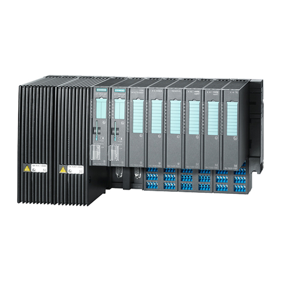
Product overview ET 200iSP Distributed I/O Station Definition The ET 200iSP distributed I/O device is a finely modular and intrinsically safe device in IP30 degree of protection. Area of application The ET 200iSP distributed I/O device can be used in the following areas: •... - Page 26 Product overview 2.1 ET 200iSP Distributed I/O Station View The following figure shows an example configuration of an ET 200iSP distributed I/O device. ① Power supply PS ② Interface module IM 152-1PN ③ Electronic modules ④ Termination module ⑤ Terminal module TM-RM/RM ⑥...
- Page 27 Product overview 2.1 ET 200iSP Distributed I/O Station ① Power supply PS ② Interface module IM 152-1DP ③ Electronic modules ④ Termination module ⑤ Terminal module TM-RM/RM ⑥ Terminal modules TM-EM/EM ⑦ Terminal module TM-IM/EM ⑧ Terminal module TM-PS-A Figure 2-2 View of the ET 200iSP distributed I/O device with IM 152-1DP Components of the ET 200iSP distributed I/O device The following table provides an overview of the most important components of a station of the...
- Page 28 Product overview 2.1 ET 200iSP Distributed I/O Station Component Function Image Terminal module ... carries the wiring and holds the power supply, inter‐ face module and the electronic modules. Terminal mod‐ ules are available in the following variants: • TM-PS-A (6ES7193-7DA10-0AA0) for the power sup‐ ply PS DC24V •...
- Page 29 Product overview 2.1 ET 200iSP Distributed I/O Station Component Function Image Interface module ...is plugged onto the terminal module. The interface module connects the station to the CPU of the automa‐ tion system and prepares the data for the assembled electronic modules.
- Page 30 Product overview 2.1 ET 200iSP Distributed I/O Station Component Function Image Ethernet switch ... converts the PROFINET IO into an optical signal when an IM 152-1PN is used. RS 485-IS coupler ... converts the PROFIBUS DP into the PROFIBUS RS 485-IS when an IM 152-1DP is used.
- Page 31 Product overview 2.1 ET 200iSP Distributed I/O Station WARNING Danger of explosion with wrong transceiver The IM 152-1PN only works with intrinsically safe SFP transceiver A5E51793919. Plugging in other transceivers may cause explosions. Do not plug another transceiver into the IM 152-1PN. Properties and benefits of ET 200iSP Table 2-3 Features and benefits...
-
Page 32: Et 200Isp In The Hazardous Area
Zone 2/ 22 Rare or short-term presence of potentially explosive Areas bordering on zone 1/ 21 gas or dust atmosphere For more information, refer to the "Principles of explosion protection (https:// support.automation.siemens.com/WW/view/en/12521844)" manual. ET 200iSP Operating Instructions, 11/2022, A5E00247483-AK... - Page 33 Product overview 2.2 ET 200iSP in the Hazardous Area Types of protection of ET 200iSP The types of protection include design and electrical measures relating to the equipment to achieve explosion protection in the hazardous areas. Table 2-5 Types of protection Type of Protection Meaning Representation...
- Page 34 Product overview 2.2 ET 200iSP in the Hazardous Area Labeling of the ET 200iSP Equipment for operation in hazardous areas is marked with an identifier indicating the hazardous environments in which the equipment can be used. The ET 200iSP has the following interfaces: Explosion protection marking Intrinsically safe protection type (up to zone 0)
- Page 35 Certificates for the ET 200iSP distributed I/O device The EC type-examination certificates and EC certificates of conformity for the ET 200iSP distributed I/O device are available on the internet at: "Service & Support (https:// www.siemens.com/automation/service&support)". ET 200iSP Operating Instructions, 11/2022, A5E00247483-AK...
- Page 36 Product overview 2.2 ET 200iSP in the Hazardous Area ET 200iSP Operating Instructions, 11/2022, A5E00247483-AK...
-
Page 37: Commissioning Guideline
Commissioning guideline Introduction Introduction These instructions will guide you step by step to a working application using a concrete example. In the process, you will learn the basic hardware and software functions of your ET 200iSP. ET 200iSP Operating Instructions, 11/2022, A5E00247483-AK... -
Page 38: Prerequisites
Commissioning guideline 3.2 Prerequisites Prerequisites Requirements The following requirements must be met: • You must be familiar with the basics of electrical and electronic engineering and the procedures relating to potentially explosive atmospheres and have experience working with computers and Microsoft® Windows™. •... -
Page 39: Materials And Tools Required To Set Up The Example
– PCS 7 (as of V9.1 SP2 and the current HSP for ET 200iSP) Media converter RJ45/FOC with SFP transceiver certified as Contact your Siemens intrinsically safe (e.g. SCALANCE X 212-2; see "Optical con‐ representative nection (https://support.industry.siemens.com/cs/ww/en/ view/109761426)") - Page 40 Commissioning guideline 3.3 Materials and Tools Required to Set Up the Example Quan Article Article number (Sie‐ Required for the configura‐ tity mens) tion variant PROFINET IO PROFIBUS DP 8 DI NAMUR 6ES7131-7RF00-0AB0 4 DO DC17.4V/27mA shut down "H" 6ES7132-7RD11-0AB0 NAMUR sensor for example, BERO 3RG 4612-1NA00...
-
Page 41: Overview Of The Configuration
Commissioning guideline 3.4 Overview of the Configuration Overview of the Configuration Overview Overview of the sample configuration (wiring and power sources not illustrated) Figure 3-1 Overview of the sample configuration ET 200iSP Operating Instructions, 11/2022, A5E00247483-AK... -
Page 42: Installing The The Sample Configuration
Installing the S7-400 1. Install the rack on a stable surface. See operating instructions Automation System S7-400: Hardware and Installation (https://support.automation.siemens.com/WW/view/en/ 1117849) 2. On the left of the rack, start by installing the separate modules (hang in - swivel into position - screw on tightly). -
Page 43: Wiring The Example Configuration For Profinet
• Fiber-optic cable with LC plug at both ends Observe the following information: – Optical connection in and through ATEX/IECEx Zone 1 or 21 (https:// support.industry.siemens.com/cs/ww/en/view/109761426) Wiring the example configuration 1. Connect the engineering tool (PG) and the PROFINET IO interface of the CPU using your own cable. - Page 44 Commissioning guideline 3.6 Wiring the example configuration for PROFINET 4. Connect the PROFINET IO interface of the CPU to the media converter using an Ethernet RJ45 cable. 5. Connect the media converter to IM 152-1PN using a fiber-optic cable with LC plugs at both ends.
-
Page 45: Wiring The Example Configuration For Profibus
Commissioning guideline 3.7 Wiring the example configuration for PROFIBUS Wiring the example configuration for PROFIBUS Wiring of the TM-PS-A Figure 3-4 Wiring TM-PS-A Wiring of the RS 485-IS coupler Figure 3-5 Wiring of the RS 485-IS coupler ET 200iSP Operating Instructions, 11/2022, A5E00247483-AK... - Page 46 Commissioning guideline 3.7 Wiring the example configuration for PROFIBUS Requirements for example configuration with PROFIBUS DP/PROFIBUS RS 485-IS • PROFIBUS DP cable with PROFIBUS bus connector at both ends (6ES7972-0BB50-0XA0) Wiring the example configuration 1. Connect the engineering tool (PG) and the PROFINET IO interface of the CPU using your own cable.
-
Page 47: Inserting The Interface Module And The Electronics Modules
Commissioning guideline 3.8 Inserting the interface module and the electronics modules ① 2 x 8 DI NAMUR ② 3 x 4 DO DC17.4/27mA ③ Terminals ④ LEDs ⑤ NAMUR sensor Figure 3-6 Wiring of the ET 200iSP modules Inserting the interface module and the electronics modules Inserting Modules Insert the modules in the following order: •... -
Page 48: Setting A Profibus Address On Im 152-1Dp
Commissioning guideline 3.9 Setting a PROFIBUS address on IM 152-1DP Setting a PROFIBUS address on IM 152-1DP Requirements You have selected the PROFIBUS configuration. Setting the PROFIBUS address Set the PROFIBUS address on the interface module IM 152-1DP. Figure 3-7 Example of the setting on PROFIBUS address 3 See also Configuring PROFIBUS DP address (Page 179) -
Page 49: Configuring The Example
Commissioning guideline 3.10 Configuring the Example 3.10 Configuring the Example 3.10.1 Configuring S7-400 Introduction The configuration of a ET 200iSP using a hardware support package (HSP) installed on the configuration tool is described below. Note Integrate ET 200iSP via GSD file If a ET 200iSP is to be operated on a CPU via PROFIBUS but the CPU cannot be operated in DPV1 mode, the ET 200iSP must be included via the GSD file. -
Page 50: Setting The Ip Address Of The Im 152-1Pn On Profinet Io
Commissioning guideline 3.10 Configuring the Example 9. Depending on the required network connection of the ET 200iSP station: – Connection to a PROFINET IO system with interface module IM 152-1PN: In the window, look for the row with the label "PN-IO" and highlight it. Right-click on the row and select Object Properties from the menu. - Page 51 Commissioning guideline 3.10 Configuring the Example 3. Enter a unique designation for the interface module in the "Device name" entry field of the "General" tab. The unique designation is mandatory for the PROFINET node. 4. Click the "Ethernet" button in the "PROFINET IO System node - Slot 0" area. The dialog window "Properties - IM 152-1PN..."...
-
Page 52: Configuring And Assigning Parameters For The Et 200Isp
Commissioning guideline 3.10 Configuring the Example 3.10.3 Configuring and assigning parameters for the ET 200iSP Procedure 1. Click with the mouse to select the stylized selected fieldbus (PROFINET IO or PROFIBUS DP) in the upper left part of the HW Config window. Now navigate in the catalog via the fieldbus (PROFINET IO or PROFIBUS DP) and ET 200iSP to the interface module and double-click it to insert an ET 200iSP station. - Page 53 Commissioning guideline 3.10 Configuring the Example 3. Double click on the first module in the configuration table (8 DI NAMUR, slot 2 for the PROFINET IO configuration, slot 4 for the PROFIBUS DP configuration) and select the "Parameters" tab. For channels 0 and 1, change the sensor type to "NAMUR sensor". For all other channels, select "disabled".
-
Page 54: Programming The Sample Configuration
Commissioning guideline 3.11 Programming the Sample Configuration 3.11 Programming the Sample Configuration Operating principle The state of the sensors connected to inputs I512.0 , I513.0 and I514.0 is looked up and analyzed. I512.0 increments an internal counter and I513.0 decrements it. Input I514.0 resets the counter to zero. -
Page 55: Putting The Example Into Operation
Commissioning guideline 3.13 Evaluating the diagnostics 3.12 Putting the Example into Operation Commissioning 1. Switch on the power supply of the ET 200iSP. 2. Observe the status LED at the S7-400 and at the ET 200iSP: LEDs of the CPU: –... -
Page 56: Removing And Inserting Of Modules
Commissioning guideline 3.14 Removing and inserting of modules 3.14 Removing and inserting of modules Pulling and plugging digital electronics module 8 DI NAMUR 1. Swing the first of the three 8 DI NAMUR electronic modules out from the terminal module during operation. -
Page 57: Wire Break Of Namur Encoder On Digital Input Module
Commissioning guideline 3.15 Wire break of NAMUR encoder on digital input module 3. Analyze the diagnostic message: Result for PROFINET configuration: – Identifier-related diagnostics: Bit 3 in byte 7 is set -> Slot 2 Result for PROFIBUS configuration: – Station status 1 (byte 0): Bit 3 is set -> External diagnostics –... - Page 58 Commissioning guideline 3.15 Wire break of NAMUR encoder on digital input module 4. Analyze the diagnostic message. Result for PROFINET configuration: – Identifier-related diagnostics: Bit 7.3 is set -> Slot 2 – Slot: 2 Subslot: 1 Channel fault type: 6 - Wire break Result for PROFIBUS configuration: –...
-
Page 59: Configurations (Principle)
Configurations (principle) Modular system Modular system With ET 200iSP, modular means: You can adapt the design to your applications by using 4‑channel and 8‑channel electronic modules. Example The following figure shows an example of the configuration of the ET 200iSP distributed I/O device: Figure 4-1 Configuration example ET 200iSP... -
Page 60: Electronics Modules Suitable For Your Application
Configurations (principle) 4.2 Electronics modules suitable for your application Electronics modules suitable for your application Selection guide for the electronic modules The following table is a selection guide for the applications of the electronic modules of the ET 200iSP distributed I/O device. Table 4-1 Which electronic modules match your application Application... -
Page 61: Terminal Modules And The Suitable Modules For Them
Configurations (principle) 4.3 Terminal modules and the suitable modules for them Application Electronic modules Measuring temperatures with thermocouples 4 input channels 4 AI TC Measuring thermoelectric voltages Input ranges • ±80 mV • Type J, K, T, U, E, L, N, R, S, Output of currents with HART field devices 4 output channels 4 AO I HART... -
Page 62: Rules For Operation In Hazardous Areas
Configurations (principle) 4.4 Rules for operation in hazardous areas Modules Terminal modules 4 AI I 4WIRE HART 4 AI RTD 4 AI TC 4 AO I HART Reserve module WATCHDOG Only available as replacement part As of product version 3 of the reserve module Rules for operation in hazardous areas 4.4.1 PROFINET configurations in zones for IM 152-1PN... - Page 63 Configurations (principle) 4.4 Rules for operation in hazardous areas Rules for the configuration of the ET 200iSP in Zone 1 If you use the ET 200iSP in zone 1, then you must observe the following rules: 1. Install the ET 200iSP in an enclosure with degree of protection Ex e (increased safety) (see section "Installation rules (Page 101)", see Appendix "Article numbers (Page 419)").
- Page 64 Configurations (principle) 4.4 Rules for operation in hazardous areas Rules for configuration of the ET 200iSP in Zone 2 If you use the ET 200iSP in zone 2, then you must observe the following rules: 1. Install the ET 200iSP in an enclosure with degree of protection IP54. A declaration of the manufacturer for fulfilment of Zone 2 must be available for the enclosure (in accordance with EN 60079‑15: Protection against mechanical damage;...
- Page 65 Configurations (principle) 4.4 Rules for operation in hazardous areas The following table describes the conditions for checking the maximum safe values for a simple, intrinsically safe circuit: Table 4-3 Rules for configuration Relevant Standard / Conditions for Electrical Parameters Usable Sensors and Actuators Standard: EN 60079-14 The maximum safe values of the sensors and actuators must be adapted to the maximum values of the electronic...
-
Page 66: Profibus Configurations In Zones For Im 152-1Dp
Configurations (principle) 4.4 Rules for operation in hazardous areas WARNING Intrinsically safe circuit Connecting an intrinsically safe sensor, actuator, or HART field device to the input/output of an electronic module must produce an intrinsically safe circuit! Always check for resultant safety values when you select the sensors, actuators and HART field devices for an electronic module. - Page 67 "Article numbers (Page 419)"). The maximum length of the PROFIBUS RS 485‑IS depends on the baud rate (see product information RS 485-IS coupler (https:// support.industry.siemens.com/cs/ww/en/view/29306413)). Figure 4-3 ET 200iSP configuration Options in Zone 1 Rules for configuration of the ET 200iSP in Zone 21 If you use the ET 200iSP in zone 21, then you must observe the following rules: 1.
- Page 68 Configurations (principle) 4.4 Rules for operation in hazardous areas Rules for configuration of the ET 200iSP in Zone 22 If you use the ET 200iSP in zone 22, then you must observe the following rules: 1. Install the ET 200iSP in a metallic (see section "Installation rules (Page 101)"), dust-protected enclosure with at least degree of protection IP5X (according to directive 2014/34/EU for category 3D).
- Page 69 Configurations (principle) 4.4 Rules for operation in hazardous areas The following table describes the conditions for checking the maximum safe values for a simple, intrinsically safe circuit: Table 4-4 Rules for configuration Relevant Standard / Conditions for Electrical Parameters Usable Sensors and Actuators Standard: EN 60079-14 The maximum safe values of the sensors and actuators must be adapted to the maximum values of the electronic...
-
Page 70: Use Of The Et 200Isp In Category M2 Of Equipment-Group I (Mining)
Configurations (principle) 4.6 Restricted Number of Connectable Electronics Modules WARNING Intrinsically safe circuit Connecting an intrinsically safe sensor, actuator, or HART field device to the input/output of an electronic module must produce an intrinsically safe circuit! Always check for resultant safety values when you select the sensors, actuators and HART field devices for an electronic module. - Page 71 Configurations (principle) 4.6 Restricted Number of Connectable Electronics Modules Calculation table With the calculation table, you can check the operational current consumption of the ET 200iSP. Note The safety-related current consumption (limit value < 15 A, see EC type-examination certificate KEMA 04 ATEX 2242) is always complied with in the ET 200iSP.
- Page 72 Configurations (principle) 4.6 Restricted Number of Connectable Electronics Modules Electronic modules x number Operational = Operational current of modules current per consumption in mA module in mA 4 DO DC23.1V/20mA shut down "H" 290 mA 4 DO DC17.4V/27mA shut down "H" 260 mA 4 DO DC17.4V/40mA shut down "H"...
- Page 73 Configurations (principle) 4.6 Restricted Number of Connectable Electronics Modules Check the number of electronic modules and the current consumption: Table 4-6 Calculation table current consumption Electronic modules x number Operational = Operational current of modules current per consumption in mA module in mA Power supply PS DC24V/ 15 mA...
-
Page 74: Maximum Configuration Of The Et 200Isp
Fail-safe modules have a higher functional current consumption than standard modules. See "ET 200iSP Distributed I/O Device - Fail-safe Modules (https:// support.industry.siemens.com/cs/us/en/view/47357221)". Calculating the ET 200iSP power loss You can calculate the power loss of the ET 200iSP using the following formula: = x*5W + 1.2*∑... -
Page 75: Power Supply Of The Et 200Isp
Configurations (principle) 4.8 Power Supply of the ET 200iSP Width of the ET 200iSP The maximum installation width of ET 200iSP is: • without redundancy: 1040 mm = 60 mm + 30 mm + 31 * 30 mm + 20 mm (power supply + interface module + 31 electronic modules + termination module) •... -
Page 76: Direct Data Exchange Via Profibus Dp
Configurations (principle) 4.9 Direct data exchange via PROFIBUS DP Direct data exchange via PROFIBUS DP Requirements The ET 200iSP can be used as a sender (publisher) for direct data exchange (direct communication). No configuration is required for this. Of course the DP master used must support direct data exchange. Additional information can be found in the description of the DP master. -
Page 77: Identification And Maintenance Data I&M
Configurations (principle) 4.10 Identification and maintenance data I&M 4.10 Identification and maintenance data I&M Properties Identification data (I data): Information about the module that is normally printed on the enclosure of the module. I data is read-only. Maintenance data (M data): System-specific information such as the installation location and date. - Page 78 I data 0: Index 1 (data record 45040 for PROFINET, data record 231 for PROFIBUS) MANUFACTOR_ID read (2 bytes) (=42 The name of the manufacturer is stored here. (42 = Siemens AG) ORDER_ID read (20 bytes) Dependent Article number of the module on the mod‐...
-
Page 79: Redundant Interface Modules In The Et 200Isp
The display of this I&M depends on the engineering software. See also Project Engineering with GSD File and SIMATIC PDM (Page 161) PROFINET IO-Base user programming interface (https://support.industry.siemens.com/cs/us/en/ view/26435491) 4.11 Redundant interface modules in the ET 200iSP 4.11.1 Introduction Properties You can operate the ET 200iSP station redundantly on the IO controller or on the DP master (e.g. -
Page 80: Redundant Interface Modules
Configurations (principle) 4.11 Redundant interface modules in the ET 200iSP Power supply of the ET 200iSP To ensure the consistently high availability in redundancy mode with two identical interface modules, we recommend additionally setting up the ET 200iSP with a redundant power supply See also Redundancy of the Power Supply (Page 82) 4.11.2... - Page 81 Configurations (principle) 4.11 Redundant interface modules in the ET 200iSP Mounting and wiring 1. Install the ET 200iSP with the terminal module TM-IM/IM. 2. Depending on the selected configuration: – PROFINET configuration: A separate media converter is required for each PROFINET IO system Connect a fiber-optic cable with an LC plug to each bus connection and connect it to the media converter.
-
Page 82: Redundancy Of The Power Supply
Configurations (principle) 4.12 Redundancy of the Power Supply Example configuration of a redundant bus system and the interface modules The following figure shows a configuration using an S7-400H as an example. You can find a detailed description of H systems in the manual S7-400H Automation system, Introduction to the system. - Page 83 Configurations (principle) 4.12 Redundancy of the Power Supply • 2 x Power Supply PS • Interface module: – For connection on the PROFINET IO: IM 152-1PN (V1.0 and higher): – For connection on the PROFIBUS DP: IM 152-1DP (V2.0 and higher): Combination options of the power supply PS with TM-PS-A (6ES7193-7DA10-0AA0) and TM‑PS‑B (6ES7193-7DB10-0AA0) TM-PS-A (6ES7193-7DA10-0AA0)
- Page 84 Configurations (principle) 4.12 Redundancy of the Power Supply 4. Connect a separate power supply to each TM. 5. Finally, fit the TMs with Power Supply PS 1 and PS 2. Figure 4-7 Redundancy of the power supply (example with IM 152-1DP) Parameter assignment Only those parameters that are relevant for the redundancy of the power supply are explained below.
-
Page 85: System Configuration In Run (Cir)
Relay UC60V/2A. Changing the parameter settings in RUN mode Observe the operating steps listed in the Changes to the plant during operation by means of CiR (https://support.automation.siemens.com/WW/view/en/14044916) function manual when re- assigning the parameters. ET 200iSP Operating Instructions, 11/2022, A5E00247483-AK... -
Page 86: System Modification In A Redundant System
Properties For information on using this function in the redundant configuration, refer to the "S7-400H automation system, high availability systems (https://support.industry.siemens.com/cs/ww/en/ view/1186523)" manual and the online help of the H option package for STEP 7. ET 200iSP Operating Instructions, 11/2022, A5E00247483-AK... - Page 87 Configurations (principle) 4.13 System configuration in RUN (CiR) Requirements PROFIBUS configuration: • Configuration with interface module IM 152-1DP • STEP 7 as of V5.3 SP2 and hardware update 0042 (version 3.0) • PCS 7 is released with the current service packs as of PCS 7 V6.1 What do you need to consider when selecting the interface module? The interface modules support the following redundancy configurations: Configuration...
-
Page 88: Operation Of The Et 200Isp Im Profibus Variant With Older Cpus
Configurations (principle) 4.15 Time synchronization with a flexible time interval 5. Replace the gaps in the configuration (HW config) with the new electronic modules. 6. Execute the Save and Compile menu command. 7. Download the station configuration to the H station in RUN mode. Result The system modification was successfully completed. -
Page 89: Time Stamping
Configurations (principle) 4.16 Time stamping 4.16 Time stamping 4.16.1 Fundamentals of Time Stamping Properties Digital modules of the ET 200iSP enable the "time stamping" function. • in customer applications using the FB 62 (FB TIMESTMP) (for more information, see the STEP 7 online help) •... - Page 90 Configurations (principle) 4.16 Time stamping Requirements • The synchronization interval must be set to 20 ms for the master and for the ET 200iSP. • For time stamping you need the electronic module 8 DI NAMUR with the configuration "8 DI NAMUR". Time stamping is not possible with all other configurations of the electronic module 8 DI NAMUR.
-
Page 91: Counting
Configurations (principle) 4.17 Counting How time stamping works in the redundant system Both interface modules store the messages of the time stamped signals. This means the "new" active interface module can forward the latest messages to the OS after switching from the active to the passive interface module. -
Page 92: Principle Of Operation
Configurations (principle) 4.17 Counting • 1 x 32-bit down counter (cascading counter function) • Setting a setpoint via the PIQ • GATE function • You can configure the control signals of the counters: – Configuration "2 Count/ 6 DI NAMUR": Two counters are configured. The control signals of the counters are stored in the POI (process output image). - Page 93 Configurations (principle) 4.17 Counting Figure 4-10 Principle of operation of the 16-bit up-counter 16-bit down counters (periodic counting function) The maximum counting range is 65535 to 0. When the counter is started, the actual value is set to the selected setpoint. The actual value is reduced by the value 1 with each counting pulse.
-
Page 94: Configuring Counters
Configurations (principle) 4.17 Counting Figure 4-11 Principle of operation of the 16-bit down counter 32-bit down counter (cascading counter function) The maximum counting range is 4294967295 to 0. The principle of operation is identical to that of the 16-bit down counter. Channel 1 has no function. - Page 95 Configurations (principle) 4.17 Counting Digital input Terminal Assignment Channel 2 9, 10 Digital input 2 Channel 3 13, 14 Digital input 3 Channel 4 3, 4 Digital input 4 Channel 5 7, 8 Digital input 5 Channel 6 11, 12 Digital input 6 Channel 7 15, 16...
-
Page 96: Assigning Parameters To Counters
Configurations (principle) 4.17 Counting Configuration "2 Count/ 6 Control" With this configuration, you can also control the counters over the digital inputs. • Assignment of the digital inputs at the electronic module 8 DI NAMUR You can find more information on the pin assignment in the technical specifications of the electronic module 8 DI NAMUR. -
Page 97: Metering Frequencies
Configurations (principle) 4.18 Metering frequencies Parameters Only the parameters that are relevant for the counters are explained below. These are part of the parameters of the electronic module 8 DI NAMUR and depend on the selected configuration: Table 4-14 Parameters for the counters Parameters Setting Description... -
Page 98: Principle Of Operation
Configurations (principle) 4.18 Metering frequencies 4.18.2 Principle of operation Frequency measurement The signal frequencies are determined from the input signals of channel 0 or 1 of the electronic module. To calculate the frequency, the signals are measured within a parameterizable measuring window. -
Page 99: Assigning Parameters For The Frequency Meters
Configurations (principle) 4.18 Metering frequencies Assignment of the process image inputs (PII) Table 4-16 PII for configuration "2 Trace/ 6 DI NAMUR" (S7 format) Description IB x Bit 15 to 8 Frequency meter 1 IB x+1 Bit 7 to 0: IB x+2 Bit 15 to 8 Frequency meter 2... - Page 100 Configurations (principle) 4.18 Metering frequencies Parameters Only the parameters that are relevant for the frequency meter are explained below. These are part of the parameters of the electronic module 8 DI NAMUR: Table 4-17 Parameters for the frequency meter Parameters Setting Description Encoder type frequency...
-
Page 101: Installing
Installing Installation rules Safety information WARNING Death or serious physical injury may result During mounting, observe the guidelines according to EN 60079-14. The conditions required by the standard for electrical parameters apply to simple circuits. See sections "PROFINET configurations in zones for IM 152-1PN (Page 62)" and "PROFIBUS configurations in zones for IM 152-1DP (Page 66)". - Page 102 Installing 5.1 Installation rules Mounting dimensions Table 5-1 Mounting dimensions Dimensions Mounting width Terminal module with power supply module 60 mm Terminal module with interface module/electronic module 60 mm Terminal module with electronic modules 60 mm Termination module 20 mm Mounting height Terminal module with power supply module 190 mm...
- Page 103 Installing 5.1 Installation rules Enclosure for ET 200iSP in Zone 21 The ET 200iSP must be installed in a dust-proof (certified) enclosure with degree of protection IP6X (according to directive 2014/34/EU for category 2D). Further requirements (surface temperature, for example) can be found in the certification document for the enclosure. See Appendix "Article numbers (Page 419)".
- Page 104 Installing 5.1 Installation rules Enclosure for ET 200iSP in Zone 2 The ET 200iSP must be installed in an enclosure with at least IP54 degree of protection certified for Zone 2 (according to EN 60079-7). See Appendix "Article numbers (Page 419)". Figure 5-3 Enclosure for ET 200iSP in Zone 2 Enclosure for ET 200iSP in Zone 22...
- Page 105 Installing 5.1 Installation rules Figure 5-4 Enclosure for ET 200iSP in Zone 22 Enclosure for ET 200iSP in the safe area The ET 200iSP must be installed in an enclosure with degree of protection IP20. Mounting position The ideal installation position is horizontal on a vertical surface. Any other installation position is also possible;...
- Page 106 Installing 5.1 Installation rules Minimum clearances to the enclosure for installation, wiring, and ventilation Figure 5-5 Minimum clearances to the enclosure Ambient temperature Mounting positions For horizontal installation of the ET 200iSP on a vertical wall • Power supply PS DC24V: –...
-
Page 107: Installing The Mounting Rail
Installing 5.2 Installing the mounting rail Rules for installation During installation, make sure that you keep to the following rules: • The mechanical design of the ET 200iSP starts with the terminal module TM-PS-A. Start with the installation of the terminal module approx. 10 mm right of the grounding pin, in order that the mounting location on the mounting rail can be optimally used. - Page 108 Installing 5.2 Installing the mounting rail Dimensions for the securing holes The following table contains the dimensions for the holes for securing mounting rails. Table 5-2 Diagram for securing mounting rails "Standard" Mounting Rail ① Mark for additional bore hole for applications with increased vibration and shock stress. Length of the Distance a Distance b...
-
Page 109: Installing The Terminal Module For Power Supply Ps
Installing 5.3 Installing the terminal module for power supply PS Installing the mounting rail 1. Mount the rail in the cabinet so that you have sufficient space for installation and heat dissipation of the modules (maintain the minimum clearance to the casing). 2. - Page 110 Installing 5.3 Installing the terminal module for power supply PS Installing terminal module TM‑PS‑A 1. Fit the terminal module onto the rail. 2. Push in the terminal module at the bottom until you can hear the catch lock. 3. Screw the terminal module to the mounting rail (2 screws - torque 0.8 to 1.1 Nm). Use a screwdriver with a 4.5 mm wide blade.
- Page 111 Installing 5.3 Installing the terminal module for power supply PS 3. Move the TM‑PS‑B to the left until it audibly latches onto the previous terminal module TM‑PS‑A. 4. Bolt the terminal module to the mounting rail. See Installing terminal module TM‑PS‑A Step Figure 5-7 Installing terminal module TM‑PS‑B Removing terminal module TM‑PS‑A or TM‑PS‑B...
-
Page 112: Installing Terminal Modules For The Interface Module And Electronics Modules
Installing 5.4 Installing Terminal Modules for the Interface Module and Electronics Modules Installing Terminal Modules for the Interface Module and Electronics Modules Properties • The terminal modules are used to accommodate the interface module and the electronic modules – TM-IM/EM: Terminal module for the interface module and electronic module, located directly to the right of the terminal module TM-PS-A –... - Page 113 Installing 5.4 Installing Terminal Modules for the Interface Module and Electronics Modules Mount terminal module TM-IM/EM, TM-IM/IM, TM-EM/EM and TM-RM/RM 1. Fit the terminal module onto the rail. 2. Push in the terminal module at the bottom until you can hear the catch lock. 3.
-
Page 114: Installing The Terminating Module And The Slot Cover
Installing 5.5 Installing the Terminating Module and the Slot Cover ① Catch Figure 5-9 Remove terminal module TM-EM/EM from right side Installing the Terminating Module and the Slot Cover Properties • The distributed I/O device ET 200iSP is terminated with the terminating module at the right end of the ET 200iSP. - Page 115 Installing 5.5 Installing the Terminating Module and the Slot Cover Required tools 4.5 mm screwdriver. Installing the terminating module 1. Hook the terminating module onto the mounting rail to the right of the last terminal module. 2. Pivot the terminating module backwards onto the mounting rail. 3.
- Page 116 Installing 5.5 Installing the Terminating Module and the Slot Cover Installing the slot cover 1. Use the screwdriver to lever the slot cover out of the terminating module. The slot cover is fixed in bracket on the right of the terminating module. 2.
-
Page 117: Installing The Slot Number Labels
Installing 5.6 Installing the Slot Number Labels Installing the Slot Number Labels Properties The slot number plates identify the individual electronic modules with a slot (1 to 34). Requirements • The terminal modules are installed. • There must not be any electronic modules inserted when you apply the slot number plates. •... - Page 118 Installing 5.6 Installing the Slot Number Labels Removing slot number plates 1. Remove the electronic module from the terminal module. 2. Using the screwdriver, lever the slot number plate carefully from below out of the bracket. ET 200iSP Operating Instructions, 11/2022, A5E00247483-AK...
-
Page 119: Wiring
Wiring General Rules and Regulations for Wiring Introduction The ET 200iSP distributed I/O device is subject to special rules and regulations depending on its application. This section provides you with an overview of the most important rules when integrating the ET 200iSP distributed I/O device a plant or system. Specific application Keep to the safety and accident prevention regulations applying to specific applications, for example, the machine protection guidelines. - Page 120 Wiring 6.1 General Rules and Regulations for Wiring Line voltage in the safe area The following table describes points to remember relating to the line voltage: Table 6-2 Line voltage in the safe area With ... Requirements A fixed installation or systems without all-pole dis‐ A disconnector or a fuse must exist in the building connector installation.
-
Page 121: Operating The Et 200Isp With Equipotential Bonding
Wiring 6.2 Operating the ET 200iSP with equipotential bonding Operating the ET 200iSP with equipotential bonding Components and protective measures When setting up a system, various components and protective devices are mandatory. The types of components and the degree to which the protective measures are mandatory depend on the DIN VDE regulation that applies to your plant setup. - Page 122 Wiring 6.2 Operating the ET 200iSP with equipotential bonding ET 200iSP in the overall configuration The following schematic shows the distributed I/O device ET 200iSP within the overall configuration in the Zone 1 hazardous area (supply voltage and grounding concept) when powered from a TN-S system.
- Page 123 Wiring 6.2 Operating the ET 200iSP with equipotential bonding Figure 6-2 Operating ET 200iSP and PS AC120/230V with equipotential bonding Note Requirement for connecting the protective conductor The connection of the protective conductor to the equipotential bonding rail, EB, is optionally possible.
-
Page 124: Electrical Design Of The Et 200Isp
According to EN 60079-14, equipotential bonding is mandatory in hazardous areas. You can find more information on equipotential bonding in the system manual "Principles of explosion protection (https://support.automation.siemens.com/WW/view/en/12521844)". Electrical Design of the ET 200iSP Electrical isolation With the ET 200iSP, there is electrical isolation between the following components: •... -
Page 125: Wiring The Et 200Isp
Wiring 6.4 Wiring the ET 200iSP Potential ET 200iSP Potential auxiliary power Potential network interface Potential I/O Figure 6-3 Potentials for ET 200iSP For IM 152-1PN, no further potentials are required. Wiring the ET 200iSP 6.4.1 Wiring Rules for the ET 200iSP DANGER Reviewing regulations When laying cables and wiring, adhere to the installation regulations in accordance with EN... - Page 126 Wiring 6.4 Wiring the ET 200iSP DANGER Check safety-related values Connecting an intrinsically safe sensor, actuator, or HART field device to the input/output of an electronic module must produce an intrinsically safe circuit! For this reason: When you select the encoder, actuator or HART field device to be connected to the electronic module, the resulting safety-related values must be checked! The inductance and capacitance of the cable must also be taken into account! Refer to Configuration Options in Zones (Page 66).
-
Page 127: Wiring Terminal Modules With Screw Terminals
Wiring 6.4 Wiring the ET 200iSP 6.4.2 Wiring Terminal Modules with Screw Terminals Properties • In terminal modules with screw terminals, the individual wires are screwed into the terminal. • Wire-end ferrules are not necessary. Prerequisites Observe the wiring rules. Required tool 3.5 mm screwdriver Procedure... -
Page 128: Grounding The Mounting Rail
Wiring 6.4 Wiring the ET 200iSP Table 6-7 Wiring the spring terminal Insert screwdriver Insert cable up to stop in spring-type terminal Pull out screwdriver; cable clamps to contact 6.4.4 Grounding the mounting rail Properties The mounting rail of the distributed I/O device must be connected to the ground bus (EB). Requirements •... -
Page 129: Wiring Terminal Module Tm-Ps-A Or Tm-Ps-B
Wiring 6.4 Wiring the ET 200iSP Procedure 1. Strip the insulation from the grounding conductor. Attach an M6 (ring) cable lug to the grounding conductor. The grounding conductor must have a cross-section of at least 4 mm 2. Attach the grounding conductor to the left of the TM-PS-A on the mounting rail on the ground bolt (M6 nut, shim washer and spring lock washer). - Page 130 Wiring 6.4 Wiring the ET 200iSP Safety note for the power supply PS AC120/230V DANGER Unplug cable only in a voltage-free state The isolating or disconnecting of the cables for the supply voltage of the power supply PS AC120/230V at the terminal module TM‑PS‑A (6ES7193-7DA20-0AA0) or TM‑PS‑B (6ES7193-7DB20-0AA0) may only be carried out in Zone 1/Zone 21, Zone 2/Zone 22 and in the safe area in a voltage-free state.
-
Page 131: Wiring Terminal Modules Tm-Im/Em And Tm-Im/Im
Wiring 6.4 Wiring the ET 200iSP 3. Secure the individual wires using the 3.5 mm screwdriver. Note The grounding conductor EB must have a cross-section of at least 4 mm . Connect the other end of the grounding conductor EB with the ground bus EB. 4. - Page 132 Wiring 6.4 Wiring the ET 200iSP At the terminal module TM-IM/IM, connect the bus connectors for redundant operation of the two interface modules. Requirements for Zone 1 and Zone 21 for the configuration with PROFINET connection DANGER Explosion hazard When the fiber-optic cables that are connected to the ET 200iSP run through hazardous areas, all devices must be certified according to the EN/IEC 60079-28 standard.
- Page 133 Wiring 6.4 Wiring the ET 200iSP Prerequisites for Zone 2 and Zone 22 Keep to the following rules in Zone 2: • See points 1 to 5: Prerequisites for Zone 1 and Zone 21 Prerequisites for safe area • See points 1 to 4: Prerequisites for Zone 1 and Zone 21 Wiring terminal module TM-IM/EM For configuration with PROFINET IO connection: Connecting FO cables 1.
- Page 134 Wiring 6.4 Wiring the ET 200iSP For configuration with PROFIBUS connection: Connect PROFIBUS RS 485‑IS (left module) 1. Insert the bus connector into the PROFIBUS RS 485‑IS connection. Note The cable shield of the bus cable is connected in service to the terminal module TM-IM/EM by means of a spring contact with the mounting rail and consequently with the equipotential bonding PA.
-
Page 135: Wiring Terminal Modules Tm-Em/Em
Wiring 6.4 Wiring the ET 200iSP Note Pulling and plugging the fiber-optic cable and transceiver during operation (hot-swapping) in Zone 1 and Zone 2. In Zone 21 and Zone 22, you may only open the enclosure of the ET 200iSP if no combustible dust is present. - Page 136 Wiring 6.4 Wiring the ET 200iSP Requirements Observe the wiring rules. Required tools 3.5 mm screwdriver Procedure 1. Strip the insulation from the wires to the sensors / actuators. 2. Secure the individual wires in the screw or spring terminals. ①...
-
Page 137: Wiring Terminal Module Tm-Rm/Rm
Wiring 6.4 Wiring the ET 200iSP 6.4.8 Wiring terminal module TM-RM/RM DANGER Threat to explosion protection in the Zone 1 and Zone 21 potentially explosive area: The isolating or disconnecting of the cables for the actuators on the terminal module TM-RM/ RM may only be carried out in Zone 1/ Zone 21 when the rated load voltage (of the relay contacts) is switched off. -
Page 138: Connecting Cable Shields
Wiring 6.4 Wiring the ET 200iSP 3. Fasten the individual lines in the screw terminal Ex e. 4. Close the terminal cover. ① Terminal module TM-RM/RM ② Connection for electronic module 2 DO Relay UC60V/2A channels 0 and 1 ③ Terminal cover Figure 6-9 Wiring terminal module TM-RM/RM... - Page 139 Wiring 6.4 Wiring the ET 200iSP • 4.5 mm screwdriver • Insulation stripper Procedure The following procedure describes an example of how to contact the shield. You can also use the enclosure features to connect the shield. 1. Mount the standard mounting rail below the ET 200iSP in the enclosure (distance to the ET 200iSP: approx.
-
Page 140: How To Connect A Tc Sensor Module
Wiring 6.4 Wiring the ET 200iSP 6.4.10 How to Connect a TC Sensor Module Properties The TC sensor module enables internal compensation of the reference junction temperature. It is included in the scope of delivery of the 4 AI TC. Requirements The TC sensor module can only be connected to terminal modules with screw terminals. -
Page 141: Inserting And Labeling The Power Supply, Interface Module, And Electronic Modules
Wiring 6.5 Inserting and labeling the power supply, interface module, and electronic modules Inserting and labeling the power supply, interface module, and electronic modules 6.5.1 Requirements Properties • The modules are mounted on the associated terminal modules. • A labeling strip enables the interface module and the electronic modules to be labeled. •... -
Page 142: Inserting Power Supply Ps
Wiring 6.5 Inserting and labeling the power supply, interface module, and electronic modules 6.5.2 Inserting power supply PS Installing the Power Supply PS 1. Hang the power supply at the top of the bearing position of the terminal module TM-PS-A. 2. -
Page 143: Inserting And Labeling The Interface Module And Electronic Modules
Wiring 6.5 Inserting and labeling the power supply, interface module, and electronic modules Uninstalling the Power Supply PS 1. Operate the slide with the 4.5 mm screwdriver on the bottom of the terminal module TM-PS- A or TM-PS-B and pull it downward until it engages. 2. - Page 144 Wiring 6.5 Inserting and labeling the power supply, interface module, and electronic modules 3. Label the module using the enclosed labeling strips. 4. Then insert the labeling strip back into the interface or electronic module. Figure 6-13 Installing and labeling interface and electronic modules WARNING Make sure that the assignment between terminal and electronic module is correct for your application.
- Page 145 Wiring 6.5 Inserting and labeling the power supply, interface module, and electronic modules Figure 6-14 Removing the interface and electronic modules Figure 6-15 Removing the IM 152-1PN interface module ET 200iSP Operating Instructions, 11/2022, A5E00247483-AK...
- Page 146 Wiring 6.5 Inserting and labeling the power supply, interface module, and electronic modules Replace defective interface or electronic module You have already removed the interface or electronic module: 1. Remove the removable part of the coding element from the new interface or electronic module.
-
Page 147: Inserting And Labeling Electronic Modules 2 Do Relay Uc60V/2A
Wiring 6.5 Inserting and labeling the power supply, interface module, and electronic modules See also Modular system (Page 59) 6.5.4 Inserting and labeling electronic modules 2 DO Relay UC60V/2A Mount and label electronic modules 2 DO Relay UC60V/2A 1. Pull out the Ex d disconnecting plug as far as it will go. 2. - Page 148 Wiring 6.5 Inserting and labeling the power supply, interface module, and electronic modules 5. Push in the bottom of the electronic module 2 DO Relay UC60V/2A power supply until it engages on the terminal module. ET 200iSP Operating Instructions, 11/2022, A5E00247483-AK...
- Page 149 Wiring 6.5 Inserting and labeling the power supply, interface module, and electronic modules 6. Swing the Ex d disconnecting plug back into the horizontal position and push it in backwards to the end stop. Pay attention that the locking lever is flush with the plug and is engaged. 7.
-
Page 150: Pulling And Plugging Optical Transceivers
Wiring 6.5 Inserting and labeling the power supply, interface module, and electronic modules Replacing a defective electronic module You have already uninstalled the electronic module: 1. Remove the removable part of the coding element from the new electronic module. The coding element is located on the underside of the electronic module. - Page 151 Wiring 6.5 Inserting and labeling the power supply, interface module, and electronic modules Mechanical design ① Blanking plugs ② SFP transceiver Figure 6-17 SFP transceiver Unused transceivers must be sealed with blanking plugs to protect the optical interface. The blanking plugs are located in the optical transceiver when it is delivered. Inserting and wiring the optical transceiver 1.
-
Page 152: Plugging And Pulling The Fiber-Optic Cable Into The Transceiver
Wiring 6.5 Inserting and labeling the power supply, interface module, and electronic modules 4. Pull the (old) optical transceiver out of the IM 152-1PN. 5. Insert the (new) optical transceiver into the IM 152-1PN until the transceiver snaps into place. 6. -
Page 153: Installation Of Fiber-Optic Cables In The Enclosure
6.5.7 Installation of fiber-optic cables in the enclosure Permissible bending radii for assembled cables When laying the cables (6XV1847-2C) assembled by SIEMENS, the bending radii must not fall below the following values: • When pulling in: 88 mm (multiple) • After pulling in: 59 mm (once) Use cable glands to avoid damage to the edges. - Page 154 Wiring 6.5 Inserting and labeling the power supply, interface module, and electronic modules ET 200iSP Operating Instructions, 11/2022, A5E00247483-AK...
-
Page 155: Commissioning And Diagnostics
Commissioning and Diagnostics Basics of commissioning and diagnostics Principle of Configuration ① Cyclic data exchange: • Payload inputs and outputs/value status ET 200iSP Operating Instructions, 11/2022, A5E00247483-AK... - Page 156 Commissioning and Diagnostics 7.1 Basics of commissioning and diagnostics ② Cyclic data exchange: • Configuration • Parameters • Read identification and maintenance data • Diagnostic interrupts ③ Acyclic data exchange: • Parameters • Read and write identification and maintenance data •...
- Page 157 Commissioning and Diagnostics 7.1 Basics of commissioning and diagnostics Parameter assignment During parameter assignment, you set the parameters of the ET 200iSP and the HART field devices. • You the engineering tool you parameterize the ET 200iSP from HW Config. •...
- Page 158 Commissioning and Diagnostics 7.1 Basics of commissioning and diagnostics Acyclic data exchange via PROFIBUS DP An acyclic data exchange takes place between the SIMATIC PDM and the PG/PC (ET 200iSP). The ET 200iSP is configured via acyclic data exchange. In addition, identification and maintenance data is transmitted and displayed in SIMATIC PDM.
-
Page 159: 200Isp On Profibus As Dpv0, S7 Dp Or Dpv1 Device
Commissioning and Diagnostics 7.2 ET 200iSP on PROFIBUS as DPV0, S7 DP or DPV1 device Note If you configure the ET 200iSP in STEP 7 with the GSD file, then SIMATIC PDM is required for parameter assignment! ET 200iSP on PROFIBUS as DPV0, S7 DP or DPV1 device ET 200iSP on PROFIBUS as DPV0, S7 DP or DPV1 device The ET 200iSP can be operated either as DPV0, S7 DP or as DPV1 device. -
Page 160: Project Engineering With Step 7
Commissioning and Diagnostics 7.3 Project engineering with STEP 7 Function DPV0 S7 DP DPV1 Comment de‐ device device vice • Time stamping If you configure the ET 200iSP with the GSD file (in HW Config), then you need SIMATIC PDM for the parameter assignment. -
Page 161: Project Engineering With Gsd File And Simatic Pdm
Commissioning and Diagnostics 7.4 Project Engineering with GSD File and SIMATIC PDM Requirements The required software was installed on the PG/ PC or PCS 7 ES. Procedure for configuring and assigning parameters 1. Start the SIMATIC Manager. 2. Configure the ET 200iSP with HW Config. –... - Page 162 • You need the GSD file. – PROFINET GSD file xxx-GSD-FILE – PROFIBUS GSD file: SI028110.GSG You can download these on the Internet from Service & Support (https://www.siemens.com/ automation/service&support). The GSD file is integrated into the configuration software as described below: Note The GSD file for the ET 200iSP is based on revision 4.
- Page 163 Commissioning and Diagnostics 7.4 Project Engineering with GSD File and SIMATIC PDM Procedure for configuring STEP 7 as of V4.02 COM PROFIBUS as of V5.0 or other configuration software 1. Start the SIMATIC Manager. 1. Start COM PROFIBUS or the configuration soft‐ ware.
- Page 164 1. Select the remote I/O object (ET 200iSP in the left pane of the SIMATIC Manager), select Open objects in the shortcut menu. 2. In the following dialog box "SIMATIC PDM device selection" select SIEMENS > ET 200iSP > Header-end and confirm with "OK".
-
Page 165: 7.5 Assigning Parameters For The Et 200Isp During Operation Using Simatic Pdm
Commissioning and Diagnostics 7.5 Assigning Parameters for the ET 200iSP during Operation using SIMATIC PDM 6. Save the changes (menu command File > Save) to update the file. 7. Load all parameters into the modules (menu command Device > Full download to device). Exit SIMATIC PDM. -
Page 166: Diagnostics Using The Process Image Input Table
Commissioning and Diagnostics 7.6 Diagnostics Using the Process Image Input Table 7. Save the changes and load the parameters and/or identification and maintenance data into the module. 8. Control step: Load the parameters and/or I&M of the module into the PG/PC again and check the new parameter assignment. -
Page 167: Diagnostic Interrupts Of The Transceiver
For a detailed description of the evaluation and processing of the respective input signals, refer to the help for the block library. See also Digital input module (Page 435) PCS 7 documentation (https://support.automation.siemens.com/WW/view/en/ 10806846/130000) Diagnostic interrupts of the transceiver Diagnostic block OB82 Diagnostics of the interface module OB82 is called if an incompatible transceiver is plugged in. - Page 168 Commissioning and Diagnostics 7.7 Diagnostic interrupts of the transceiver In the dialog of the module status tab, you can display the following channel-specific diagnostic data for the selected transceiver: Channel-specific Channel Exten‐ Meaning Remedy diagnostics error type channel (CET) error type (ECET) SFP –...
- Page 169 Commissioning and Diagnostics 7.7 Diagnostic interrupts of the transceiver Channel-specific Channel Exten‐ Meaning Remedy diagnostics error type channel (CET) error type (ECET) SFP – RXPower 0x8007 0x8007 The optical Rx power drops 1. Check to ensure that the alarm limit is set to threshold violation below the low alarm limit.
-
Page 170: Status And Error Leds On The Im 152-1Pn
Commissioning and Diagnostics 7.8 Status and error LEDs on the IM 152-1PN Status and error LEDs on the IM 152-1PN Interface module IM 152-1PN Group error (red) Maintenance demanded (orange) Active IM with redundancy (orange) Connection status (green) Operating state Power Supply PS 1 (green, right PS) Operating state Power Supply PS 2 (green, left PS) Operating state transceiver 1 (green, front transceiver) Operating state transceiver 2 (green, rear transceiver) - Page 171 Commissioning and Diagnostics 7.8 Status and error LEDs on the IM 152-1PN ① LEDs ② Labeling strips ③ Transceiver 1 ④ Transceiver 2 Figure 7-2 Interface module IM 152-1PN Status and error LEDs on the IM 152-1PN • LED PS1: On --> power supply is switched on at Power Supply 1 •...
- Page 172 Commissioning and Diagnostics 7.8 Status and error LEDs on the IM 152-1PN LEDs Meaning Remedy Flash‐ Maintenance required Check the process wiring. Check the electronic modules. Active data exchange with the input and output modules takes place via this inter‐ face module.
-
Page 173: Status And Error Leds On The Im 152-1Dp
Commissioning and Diagnostics 7.9 Status and error LEDs on the IM 152-1DP Status and error LEDs on the IM 152-1DP Interface module IM 152-1DP Group error (red) Bus fault (red) Active IM with redundancy (yellow) Supply voltage (green) Power Supply PS 1 status (green, right-hand PS) Power Supply PS 2 status (green, left-hand PS) Status and error LEDs on the IM 152-1DP •... - Page 174 Flash‐ The IM 152-1DP is in the safe state. Pull and plug the IM 152-1DP. If the flash 2 Hz 2 Hz code continues to occur, contact Siemens 2 Hz 2 Hz Support. * Not applicable ** After the transition to redundant operation, the SF LED flashes for another 20 s.
-
Page 175: Status And Error Leds On The Electronic Modules Of The Et 200Isp
Commissioning and Diagnostics 7.10 Status and error LEDs on the electronic modules of the ET 200iSP 7.10 Status and error LEDs on the electronic modules of the ET 200iSP Digital electronic modules Group error (red) ① Status for input/output status (green) ②... - Page 176 Commissioning and Diagnostics 7.10 Status and error LEDs on the electronic modules of the ET 200iSP Status and Error LEDs on the Digital Electronic Modules Table 7-5 Status and Error LEDs on the Digital Electronic Modules LEDs Meaning Remedy Wrong module inserted or diagnostic mes‐ Analyze the diag‐...
-
Page 177: Commissioning And Starting Up The Et 200Isp
Commissioning and Diagnostics 7.11 Commissioning and starting up the ET 200iSP WATCHDOG module Group error (red) ① Bit 0: Status (green) Status and error LEDs on the WATCHDOG module Table 7-7 Status and error LEDs on the WATCHDOG module LEDs Meaning Remedy Bit 0... -
Page 178: Requirements For Commissioning
Commissioning and Diagnostics 7.11 Commissioning and starting up the ET 200iSP Perform tests Note You must ensure the safety of your installation. Before the final commissioning of a system, you should perform a complete function test and the necessary safety tests. In the tests, also plan for foreseeable possible errors. -
Page 179: Configuring The Profinet Connection
Commissioning and Diagnostics 7.11 Commissioning and starting up the ET 200iSP 7.11.3 Configuring the PROFINET connection Properties With the PROFINET IO parameters you define at which address the ET 200iSP distributed I/O device is addressed at the PROFINET IO. Requirements •... - Page 180 Commissioning and Diagnostics 7.11 Commissioning and starting up the ET 200iSP Requirements • The PROFIBUS DP address for the ET 200iSP is set on the interface module via DIP switch. The DIP switch is located on the front of the interface module, protected by a swivel cover. •...
-
Page 181: Commissioning The Et 200Isp
Commissioning and Diagnostics 7.11 Commissioning and starting up the ET 200iSP Note If you change the PROFIBUS DP address without first deleting the retentive parameters in the flash memory, then the ET 200iSP does not log on to the PROFIBUS DP with either the new or the old address. -
Page 182: Startup Of Et 200Isp With Im 152-1Pn
Commissioning and Diagnostics 7.11 Commissioning and starting up the ET 200iSP 7.11.6 Startup of ET 200iSP with IM 152-1PN Figure 7-4 Startup of the ET 200iSP with IM 152-1PN ET 200iSP Operating Instructions, 11/2022, A5E00247483-AK... -
Page 183: Startup Of Et 200Isp With Im 152-1Dp
Commissioning and Diagnostics 7.11 Commissioning and starting up the ET 200iSP 7.11.7 Startup of ET 200iSP with IM 152-1DP Figure 7-5 Startup of the ET 200iSP with IM 152-1DP ET 200iSP Operating Instructions, 11/2022, A5E00247483-AK... -
Page 184: Startup Of The Et 200Isp With Redundancy Of The Im 152-1Pn
Commissioning and Diagnostics 7.11 Commissioning and starting up the ET 200iSP 7.11.8 Startup of the ET 200iSP with redundancy of the IM 152-1PN Operating principle In the case of redundancy, the two plugged IM 152-1PN start up independently of each other. The following flow diagram shows the startup of the IM 152-1PN (a, left interface module). - Page 185 Commissioning and Diagnostics 7.11 Commissioning and starting up the ET 200iSP Figure 7-7 Startup of the ET 200iSP with redundancy of the IM 152-1PN ET 200iSP Operating Instructions, 11/2022, A5E00247483-AK...
-
Page 186: Starting The Et 200Isp With Redundancy Of The Im 152-1Dp
Commissioning and Diagnostics 7.11 Commissioning and starting up the ET 200iSP 7.11.9 Starting the ET 200iSP with redundancy of the IM 152-1DP Operating principle In the case of redundancy, the two plugged IM 152-1DP start up independently of each other. The following flow diagram shows the startup of the IM 152-1DP (a). - Page 187 Commissioning and Diagnostics 7.11 Commissioning and starting up the ET 200iSP Figure 7-9 Startup of the ET 200iSP with redundancy of the IM 152-1DP ET 200iSP Operating Instructions, 11/2022, A5E00247483-AK...
-
Page 188: Startup For Time Synchronization / Time Stamping Of Signal Changes
Commissioning and Diagnostics 7.11 Commissioning and starting up the ET 200iSP 7.11.10 Startup for time synchronization / time stamping of signal changes Principle of operation Figure 7-10 Startup for time synchronization/time stamping ET 200iSP Operating Instructions, 11/2022, A5E00247483-AK... -
Page 189: Diagnostics With Step 7 With Profinet
Diagnostics with STEP 7 with PROFINET 7.12.1 Reading the diagnostics for PROFINET PROFINET uses the standard diagnostics. See System software for S7-300/400 System and standard functions (https://support.automation.siemens.com/WW/view/en/1214574). 7.12.2 Diagnostic messages of the electronic modules with PROFINET Introduction You can set parameters for the diagnostic messages of the following modules: •... - Page 190 Commissioning and Diagnostics 7.12 Diagnostics with STEP 7 with PROFINET Digital output module 2 DO Relay UC60V/2A Table 7-12 Digital output module 2 DO Relay UC60V/2A Diagnostic message Applicability Can be set Error Module Analog input modules Table 7-13 Analog input modules Diagnostic message Applicability Can be set...
-
Page 191: Evaluating Interrupts Of The Et 200Isp By The Cpu With Profinet
In case of an interrupt, interrupt OBs run automatically in the CPU (see programming manual System software for S7-300/S7-400, program draft (http:// support.automation.siemens.com/WW/view/en/1136533)). Triggering of a diagnostic interrupt With an incoming or outgoing event (wire break, for example) the module triggers a diagnostic interrupt upon "Release: Diagnostic Interrupt". - Page 192 Bit no. 27: Violation of the high limit channel 3 Note A description of the OB40 can be found in the reference manual System and standard functions (https://support.automation.siemens.com/WW/view/en/1214574). Triggering of a remove/insert interrupt Pull/plug interrupts are only supported for S7-400 or in DPV1 mode.
-
Page 193: Diagnostics Of The Im 152-1Pn
Select the menu command PLC > Module information ..– Connection status Called from Start menu Siemens SIMATIC programs: STEP 7 > NCM S7 > Diagnostics – Inventory data Called up via Siemens SIMATIC program: SIMATIC > SIMATIC Management Console (license required) >... -
Page 194: Error Types Of The Electronic Modules With Profinet
Commissioning and Diagnostics 7.12 Diagnostics with STEP 7 with PROFINET There can be more than one diagnostic message at the same time. Table 7-17 Diagnostic messages, their meaning and possible remedies Diagnostic message Channel Extended Meaning Remedy error type channel er‐ (CET) ror type (ECET) - Page 195 Commissioning and Diagnostics 7.12 Diagnostics with STEP 7 with PROFINET Error type Error text Meaning Remedy 00110 Wire break Correction of the process inter‐ • Signal line to an encoder inter‐ connection rupted • Signal line to an actuator in‐ terrupted •...
-
Page 196: Diagnostics For Incorrect Configuration States Of The Et 200Isp With Profinet
Commissioning and Diagnostics 7.12 Diagnostics with STEP 7 with PROFINET Error type Error text Meaning Remedy 11010 External fault • Encoder error • Replacement of encoder/ actuator/HART field device • Encoder supply faulty • Correction of the process • Changeover contact error wiring •... -
Page 197: Diagnostics With Step 7 With Profibus
Read out data records (DS0/1) of S7 System and standard functions (https:// diagnostics (store in data area of user support.automation.siemens.com/WW program) /view/en/1214574) Example of reading out the S7 diagnostics with SFC 13 "DPNRM_DG". Here you find an example how to read the device diagnostics for a DP device in the STEP 7 user program with the SFC 13. -
Page 198: Diagnostic Messages Of The Electronic Modules With Profibus
Commissioning and Diagnostics 7.13 Diagnostics with STEP 7 with PROFIBUS STEP 7 user program Explanation Read request Call SFC 13 Diagnostic address of the ET 200iSP REQ :=TRUE RET_VAL from SFC 13 LADDR :=W#16#3FE Data compartment for the diagnostics in DB 82 RET_VAL :=MW 0 Read process runs over several OB1 cycles RECORD :=P#DB82.DBX 0.0 BYTE 96... - Page 199 Commissioning and Diagnostics 7.13 Diagnostics with STEP 7 with PROFIBUS Digital output module 2 DO Relay UC60V/2A Table 7-22 Digital output module 2 DO Relay UC60V/2A Diagnostic message Applicability Can be set Error Module Analog input modules Table 7-23 Analog input modules Diagnostic message Applicability Can be set...
-
Page 200: Evaluating Interrupts Of The Et 200Isp By The Cpu With Profibus
In case of an interrupt, interrupt OBs run automatically in the CPU (see programming manual System software for S7-300/S7-400, program draft (http:// support.automation.siemens.com/WW/view/en/1136533)). Evaluate interrupts at PROFIBUS with other DP master If you operate the ET 200iSP with another DP master or as DP standard device, then no interrupts are generated. - Page 201 Bit no. 27: Violation of the high limit channel 3 Note A description of the OB40 can be found in the reference manual System and standard functions (https://support.automation.siemens.com/WW/view/en/1214574). Triggering of a remove/insert interrupt If you use only DPV0 mode, no interrupts are supported.
-
Page 202: Configuration Of Device Diagnostics For Profibus
Commissioning and Diagnostics 7.13 Diagnostics with STEP 7 with PROFIBUS The CPU interrupts the processing of the user program and processes the diagnostic block OB56. The event which led to the triggering of the interrupt is entered in the start information of the OB56. - Page 203 Commissioning and Diagnostics 7.13 Diagnostics with STEP 7 with PROFIBUS Station status 1 Table 7-28 Setup of station status 1 (byte 0) Meaning Cause - remedy 1: The DP device cannot be ad‐ • Correct PROFIBUS address set on the DP device? dressed by the DP master.
-
Page 204: Master Profibus Address
Commissioning and Diagnostics 7.13 Diagnostics with STEP 7 with PROFIBUS Meaning 1: The DP device has received the control command "FREEZE". 1: The DP device has received the control command "SYNC". 0: Bit is always set to "0". 1: Bit is always set to "0". Note: When reading the station status from the DP master, the bit is "1"... -
Page 205: Identifier-Related Diagnostics In Profibus
Commissioning and Diagnostics 7.13 Diagnostics with STEP 7 with PROFIBUS Manufacturer's ID Table 7-31 Configuration of the manufacturer's ID Byte 4 Byte 5 Manufacturer ID for IM 152-1DP 7.13.9 Identifier-related diagnostics in PROFIBUS Evaluation of the device diagnostics The following figure describes a procedure of how you can systematically evaluate the device diagnostics. -
Page 206: Module Status In Profibus
Commissioning and Diagnostics 7.13 Diagnostics with STEP 7 with PROFIBUS The identifier-related diagnostics for ET 200iSP is configured as follows: Table 7-33 Configuration of the identifier-related diagnostics for ET 200iSP Byte Description Byte 6 Bit 0 to 5: Length of the identifier-related diagnostics including byte 6 (= 6 bytes) Bit 6 and Bit 7: Code for identifier-related diagnostics Byte 7... -
Page 207: Channel-Related Diagnostics With Profibus
Commissioning and Diagnostics 7.13 Diagnostics with STEP 7 with PROFIBUS Byte Description Byte 22 Slot 25 to 28 Byte 23 Slot 29 to 32 Byte 24 Slot 33 to 35 Legend for the entry of the module status on slot x: •... - Page 208 Commissioning and Diagnostics 7.13 Diagnostics with STEP 7 with PROFIBUS Channel-related diagnostics The maximum number of channel-related diagnostics is limited by the maximum total length of the device diagnostics of 96 bytes with IM 152-1DP. The length of the device diagnostics depends on the number of channel-related diagnostics currently present.
-
Page 209: Error Types Of The Electronic Modules With Profibus
Commissioning and Diagnostics 7.13 Diagnostics with STEP 7 with PROFIBUS 7.13.12 Error types of the electronic modules with PROFIBUS Table 7-37 Error types of the electronic modules Error type Error text Meaning Remedy 00001 Short-circuit Correction of the process wiring •... - Page 210 Commissioning and Diagnostics 7.13 Diagnostics with STEP 7 with PROFIBUS Error type Error text Meaning Remedy 10001 Encoder- or load • Supply voltage at the Power • Check the supply voltage at voltage missing Supply PS missing or too low the Power Supply PS •...
-
Page 211: H Status With Profibus (Only For S7-400H And Standard Redundancy)
Commissioning and Diagnostics 7.13 Diagnostics with STEP 7 with PROFIBUS Note Control response A control behavior is implemented in the electronic modules of the ET 200iSP for parameter assignment. If the electronic module receives a faulty parameter, this is rejected. The electronic then continues to operate with its already valid parameters (the default parameters from the initial parameter assignment). -
Page 212: Interrupts In Profibus
Commissioning and Diagnostics 7.13 Diagnostics with STEP 7 with PROFIBUS Byte Description Byte x+6 0 H status of the other IM 152-1DP Bit 0: Disabled Bit 1: Activated Bit 2: Hardware defect Bit 3: IM 152-1DP in the data exchange Bit 4: Master-State-Clear Byte z+7 Always "0"... - Page 213 Commissioning and Diagnostics 7.13 Diagnostics with STEP 7 with PROFIBUS Interrupts The interrupt part for ET 200iSP is configured as follows: Table 7-39 Structure of the interrupt status of the interrupt section Byte Description Byte x Bit 0 to 5: Length of the interrupt part including byte x (= max.
- Page 214 Commissioning and Diagnostics 7.13 Diagnostics with STEP 7 with PROFIBUS The bytes from byte x+8 to x+43 correspond to diagnostic data record 1 in STEP 7. Table 7-40 Structure of bytes x+4 to x+7 for diagnostic interrupt Byte Description Byte x+4 0 Bit 0: Module fault, i.e.
- Page 215 Commissioning and Diagnostics 7.13 Diagnostics with STEP 7 with PROFIBUS Byte Description Byte x+16 39 38 37 36 35 34 33 32 Byte x+17 47 46 45 44 43 42 41 40 Byte x+18 55 54 53 52 51 50 49 48 Byte x+19 63 62 61 60 59 58 57 56 Byte x+20...
- Page 216 Commissioning and Diagnostics 7.13 Diagnostics with STEP 7 with PROFIBUS Byte Description Byte x+36 Error type on channel 6: See Byte x+12 to x+15 ... x+39 Byte x+40 Error type on channel 7: See Byte x+12 to x+15 ... x+43 Diagnostic interrupt of input or output modules with HART Table 7-43 Configuration from byte x+8 for diagnostic interrupt (input or output modules with HART)
- Page 217 Commissioning and Diagnostics 7.13 Diagnostics with STEP 7 with PROFIBUS Example of a diagnostic interrupt The electronic module 8 DI NAMUR reports the diagnostic interrupt "Wire break" on channel 2. Table 7-44 Example of a diagnostic interrupt Byte Description Byte x Bit 0 to 5: Length of the interrupt part = 44 bytes Bit 7: Code for device-specific diagnostics Byte x+1...
- Page 218 Commissioning and Diagnostics 7.13 Diagnostics with STEP 7 with PROFIBUS Hardware interrupt for analog input modules Table 7-45 Configuration from byte x+4 for hardware interrupt (analog input) Byte Description Byte x+4 Bit 0: 1: Violation of the high limit channel 0 Bit 1: 1: Violation of the high limit channel 1 Bit 2: 1: Violation of the high limit channel 2 Bit 3: 1: Violation of the high limit channel 3...
- Page 219 Commissioning and Diagnostics 7.13 Diagnostics with STEP 7 with PROFIBUS Pull/plug interrupt The byte x+4 to x+8 contains the identification of the module that was removed or inserted. The identifier for the individual modules can be found in the GSD file. You can tell whether the modules have been pulled out or plugged in by the interrupt type in byte x+1 (see table Configuration of the interrupt status of the interrupt part).
-
Page 220: Diagnostics For Incorrect Configuration States Of The Et 200Isp With Profibus
Commissioning and Diagnostics 7.14 Changing PROFIBUS station to PROFINET station Table 7-49 Configuration from byte x+4 for update interrupt Byte Description Byte x+4 Data record index: Is the number of the parameter assign‐ ment data record that led to the update interrupt. Byte x+5 Number of updates that could not be reported to the CPU. - Page 221 Commissioning and Diagnostics 7.14 Changing PROFIBUS station to PROFINET station Requirements Software requirements: • PCS7 V9.1 SP2 • Step 7 V5.7 SP1 • S7 F-systems V6.4 Update 1 • PDM V9.2.2 • Latest version of the HSPs of the interface module and electronic modules: –...
- Page 222 Commissioning and Diagnostics 7.14 Changing PROFIBUS station to PROFINET station 5. Install the optical transceiver into the IM 152-1PN interface module (or both interface modules for R1 redundancy). See section "Pulling and plugging optical transceivers (Page 150)". 6. Plug the IM 152-1PN interface module (or both interface modules in case of R1 redundancy) into the existing termination module.
- Page 223 Commissioning and Diagnostics 7.14 Changing PROFIBUS station to PROFINET station Figure 7-11 Changing a PROFIBUS station (right) to a PROFINET station (left) ET 200iSP Operating Instructions, 11/2022, A5E00247483-AK...
- Page 224 Commissioning and Diagnostics 7.14 Changing PROFIBUS station to PROFINET station ET 200iSP Operating Instructions, 11/2022, A5E00247483-AK...
-
Page 225: Maintenance
Maintenance Activities during operation Properties The following table describes which activities are permitted on the ET 200iSP in Zone 1, Zone 2, Zone 21 and Zone 22 during operation. Requirements WARNING Death or serious injury may occur if the following precautions are not taken. Hazardous location zone 1 and zone 2: You may open the enclosure of the ET 200iSP briefly for the permitted maintenance work. - Page 226 Maintenance 8.1 Activities during operation Activities Zone 1 Zone 2 Zone 21 Zone 22 See section ... Firmware update of the IM 152-1PN via PROFINET IO Maintenance (Page 225) Firmware update of the IM 152-1DP via PROFIBUS DP Maintenance (Page 225) In areas with combustible dust, the enclosure of the ET 200iSP may not be opened for this handling/activity.
-
Page 227: Pulling And Plugging Electronic Modules During Operation (Hot Swapping)
Maintenance 8.2 Pulling and plugging electronic modules during operation (hot swapping) Pulling and plugging electronic modules during operation (hot swapping) Properties • The ET 200iSP distributed I/O device supports the removing and inserting of an electronic module (1 gap) during operation (RUN mode). •... - Page 228 Maintenance 8.2 Pulling and plugging electronic modules during operation (hot swapping) • IM 152-1DP: After loading the ET 200iSP, all current parameters and identification and maintenance data are stored in the interface module. After replacing an electronic module, the interface module automatically transfers the current parameters and identification and maintenance data to the new module.
-
Page 229: Replacing Interface Module Im 152-1Pn
Maintenance 8.3 Replacing interface module IM 152-1PN Requirements • During startup of the ET 200iSP all modules must be inserted. • Removing and inserting electronic modules during operation (RUN mode) is only possible if you have enabled the parameter Operation at preset <> actual configuration on the interface module. -
Page 230: Replacing Interface Module Im 152-1Dp
Maintenance 8.4 Replacing interface module IM 152-1DP Requirements • The ET 200iSP was already loaded. • There is an active communication connection to the CPU. Optical transceiver WARNING Disconnecting the fiber-optic cable Do not look directly at the end of the fiber optic cables (do not look into the opening of the optical transmitting diodes). -
Page 231: Maintenance During Operation
Maintenance 8.5 Maintenance during operation Replacing the interface module on the PROFIBUS DP Note Switching the bus terminating resistor When switching the bus terminating resistor on and off, the PROFIBUS DP line remains connected. 1. Note the setting of the bus terminating resistor on the IM to be replaced. 2. -
Page 232: Cleaning
Maintenance 8.6 Cleaning Requirements In the hazardous area, the visual inspection should be performed every 6 months. Procedure 1. Check the tightness and the integrity of the enclosure's cable entries. 2. Check whether there is any water or dust inside the enclosure. If there is, find out how it got there. -
Page 233: Firmware Update Of The Im 152-1Pn
• After (compatible) function extensions, security updates or performance improvements, you should upgrade (update) the interface module to the latest firmware version. • You can obtain the most recent firmware versions from your Siemens representative, or download it from the Internet at: http://www.siemens.com/automation/service&support (https://www.siemens.com/automation/service&support) -
Page 234: Firmware Update Of The Im 152-1Dp
• After (compatible) function extensions or after performance improvements, you should upgrade (update) the interface module to the latest firmware version. • You can obtain the most recent firmware versions from your Siemens representative, or download it from the Internet at: http://www.siemens.com/automation/service&support (https://www.siemens.com/automation/service&support) -
Page 235: Reading Service Data
Maintenance 8.9 Reading service data • The files with the current (new) firmware version are available in the file system of your PG/ • You have selected the header.upd file. Updating firmware via network connection For information on the procedure, see the STEP 7 online help. Restarting following an update The following setting options are available via the "Update firmware after download"... -
Page 236: Resetting The Im 152-1Pn To Factory Settings Using Step 7
Maintenance 8.10 Resetting the IM 152-1PN to factory settings using STEP 7 The service data can be read out from the following FW version of the interface module: • PROFINET IM 152-1PN: As of FW version V1.0.0 • PROFIBUS IM 152-1DP: As of FW version V2.0.5 You can read out the service data with the menu command "PLC ->... -
Page 237: Resetting The Interface Module Im 152-1Dp To The Factory Settings
Maintenance 8.11 Resetting the interface module IM 152-1DP to the factory settings Procedure Note Redundant configuration For an IO device with 2 interface modules (redundant configuration), this action must be performed separately for each interface module. 1. Select the interface module. 2. - Page 238 Maintenance 8.11 Resetting the interface module IM 152-1DP to the factory settings ET 200iSP Operating Instructions, 11/2022, A5E00247483-AK...
-
Page 239: General Technical Specifications
• 2014/30/EU "Electromagnetic Compatibility" (EMC Directive) • 2014/34/EU "Equipment and protective systems intended for use in potentially explosive atmospheres" (Explosion-protection directive) The EC Declarations of Conformity are available to the responsible authorities at: Siemens AG Process Automation DI PA AE Östliche Rheinbrückenstr. 50... - Page 240 General technical specifications 9.2 Standards and certifications Use in industrial environment Table 9-1 Use in industrial environment Area of application Requirement for Interference emission Interference immunity Industry EN 61000-6-4:2007 + A1:2011 EN 61000-6-2:2005 Use in residential areas Note The distributed I/O system ET 200iSP is intended for use in industrial environments; when used in residential areas, it can affect radio/television reception.
- Page 241 General technical specifications 9.2 Standards and certifications UKCA DEKRA 21UKEX0032 (ET 200iSP system) Importer UK: Siemens plc Manchester M20 2UR See technical specifications of the ET 200iSP modules. Marking for The ET 200iSP distributed I/O device meets the require‐ Australia ments of standard EN 61000-6-4:2007 + A1:2011.
-
Page 242: Electromagnetic Compatibility, Transport And Storage Conditions
General technical specifications 9.3 Electromagnetic compatibility, transport and storage conditions Use of the ET 200iSP distributed I/O device in device group I (mining) Category M2 The following conditions must be fulfilled if the ET 200iSP is used in device group I (underground mining operations and their overground systems) Category M2: CAUTION Transport and storage of the ET 200iSP... - Page 243 General technical specifications 9.3 Electromagnetic compatibility, transport and storage conditions Pulse-shaped interference Test voltage Corresponds to degree of severity High-energy single pulse (surge) in accordance with IEC 61000-4-5 As of product version 3 of power supply PS (6ES7138-7EA01-0AA0), the over‐ voltage suppressor for the DC 24V supply at the power supply PS is no longer mandatory.
- Page 244 General technical specifications 9.3 Electromagnetic compatibility, transport and storage conditions HF radiation according to IEC 61000-4-3 Electromagnetic HF field, amplitude-modulated 80 to 1000 MHz; 1.4 to 2 GHz 2.0 GHz to 2.7 GHz 10 V/m 3 V/m 80 % AM (1 kHz) •...
-
Page 245: Mechanical And Climatic Environmental Conditions
General technical specifications 9.4 Mechanical and climatic environmental conditions Mechanical and climatic environmental conditions Operating conditions The ET 200iSP is intended for weather-protected, stationary use. The operating conditions exceed requirements according to DIN IEC 60721-3-3: • Class 3M3 (mechanical requirements) •... -
Page 246: Information On Dielectric Strength Tests, Class Of Protection, Degree Of Protection And Rated Voltage Of The Et 200Isp
General technical specifications 9.5 Information on dielectric strength tests, class of protection, degree of protection and rated voltage of the ET 200iSP Test of mechanical environmental conditions The table below provides important information with respect to the type and scope of the test of ambient mechanical conditions. - Page 247 General technical specifications 9.5 Information on dielectric strength tests, class of protection, degree of protection and rated voltage of the ET 200iSP Rated voltage for operation The ET 200iSP distributed I/O station operates with the rated voltage shown in the following table and the corresponding tolerances.
- Page 248 General technical specifications 9.5 Information on dielectric strength tests, class of protection, degree of protection and rated voltage of the ET 200iSP ET 200iSP Operating Instructions, 11/2022, A5E00247483-AK...
-
Page 249: Terminal Modules
Terminal modules 10.1 Terminal modules and the suitable modules for them Modules and terminal modules The table below shows you which modules you can use on the various terminal modules. Table 10-1 Modules and terminal modules Modules Terminal modules TM-PS-A TM-PS-A TM-IM/IM TM-IM/EM 60S... -
Page 250: Terminal Modules Tm-Ps-A And Tm-Ps-B
Terminal modules 10.2 Terminal Modules TM-PS-A and TM-PS-B 10.2 Terminal Modules TM-PS-A and TM-PS-B Article number Type Article number TM‑PS‑A 6ES7193-7DA10-0AA0, only still available as spare part TM‑PS‑A 6ES7193-7DA20-0AA0 TM‑PS‑B 6ES7193-7DB10-0AA0, only still available as spare part TM‑PS‑B 6ES7193-7DB20-0AA0 Properties •... - Page 251 Terminal modules 10.2 Terminal Modules TM-PS-A and TM-PS-B Pin assignment TM‑PS‑A (6ES7193-7DA10-0AA0) and TM‑PS‑B (6ES7193-7DB10-0AA0) Table 10-2 Pin assignment on the terminal modules TM‑PS‑A (6ES7193-7DA10-0AA0) and TM‑PS‑B (6ES7193-7DB10-0AA0) View Terminal Designation Supply voltage for the plugged power sup‐ ply PS DC24V Equipotential bonding Pin assignment TM‑PS‑A (6ES7193-7DA20-0AA0) and TM‑PS‑B (6ES7193-7DB20-0AA0) Table 10-3...
- Page 252 Terminal modules 10.2 Terminal Modules TM-PS-A and TM-PS-B Block diagram ① Power bus ② Interface module ③ Backplane bus ④ Equipotential bonding ⑤ Supply voltage terminals Figure 10-1 Block diagram of terminal module TM‑PS‑A and TM‑PS‑B Technical specifications Terminal module TM‑PS‑A Article number 6ES7193-7DA20-0AA0 Standards, approvals, certificates...
- Page 253 For TM‑PS‑A (6ES7193-7DA20-0AA0), TM‑PS‑B (6ES7193-7DB20-0AA0): U = 264 VAC max; I = 5 A max For additional information, see certificate IECEx KEM 05.0003 https://www.iecex.com (https://www.iecex.com) INMETRO UL-BR 12.0077 https://support.industry.siemens.com (https://support.industry.siemens.com) * See "Wiring Rules for the ET 200iSP (Page 125)". Approvals ATEX...
-
Page 254: Terminal Modules Tm-Im/Em 60S And Tm-Im/Em 60C
Terminal modules 10.3 Terminal modules TM-IM/EM 60S and TM-IM/EM 60C INMETRO BR-Ex eb [ia Ga/ib] IIC T4 Gb BR-Ex eb [ia IIIC Da] IIC T4 Gb BR-Ex eb [ia/ib] Mb Class I, Zone 1, AEx eb [ib/ia] IIC T4; Ex eb [ib/ia] IIC T4 Class I, DIV. - Page 255 Terminal modules 10.3 Terminal modules TM-IM/EM 60S and TM-IM/EM 60C • Self-generating interference leakage from the terminal module to the mounting rail by means of a spring contact • Prewiring of the terminal module is possible Note The cable shield of the PROFIBUS DP cable is operationally connected to the equipotential bonding via the spring contact to the mounting rail.
- Page 256 Terminal modules 10.3 Terminal modules TM-IM/EM 60S and TM-IM/EM 60C Block diagram ① Supply of the interface modules ② Power bus ③ Backplane bus ④ Terminals with connection to the electronic module ⑤ Terminal PROFIBUS RS 485-IS Figure 10-2 Block diagram of terminal module TM-IM/EM Technical specifications Terminal module TM-IM/EM 60S Article number...
- Page 257 Terminal modules 10.3 Terminal modules TM-IM/EM 60S and TM-IM/EM 60C Terminal module TM-IM/EM 60C Article number 6ES7193-7AA10-0AA0 Standards, approvals, certificates CE mark Use in hazardous areas • ATEX marking see ET 200iSP system Dimensions Width 60 mm Height 190 mm Depth 52 mm Weights...
-
Page 258: Terminal Module Tm-Im/Im
Ex e [ia Ga/ib] IIC T4 Gb Ex e [iaD] IIC T4 Gb UKCA DEKRA 21UKEX0032 See also https://www.iecex.com (https://www.iecex.com) https://support.industry.siemens.com (https://support.industry.siemens.com) 10.4 Terminal module TM-IM/IM Article number 6ES7193-7AB00-0AA0 Properties • Terminal module for two interface modules (left and right side) with redundancy of the interface modules: –... - Page 259 Terminal modules 10.4 Terminal module TM-IM/IM Pin assignment Table 10-5 Pin assignment on the TM‑IM/IM View Terminal Designation Equipotential bonding RxD/TxD-P Data line B ISGND Bus termination ground Bus termination P RxD/TxD-N Data line A Block diagram ① IM 152-1DP supply ②...
- Page 260 Terminal modules 10.4 Terminal module TM-IM/IM Technical specifications Article number 6ES7193-7AB00-0AA0 Standards, approvals, certificates CE mark Use in hazardous areas see ET 200iSP system • ATEX marking Dimensions Width 60 mm Height 190 mm Depth 52 mm Weights Weight, approx. 195 g Technical specifications Module-specific data...
-
Page 261: Terminal Modules Tm-Em/Em 60S And Tm-Em/Em 60C
Terminal modules 10.5 Terminal modules TM-EM/EM 60S and TM-EM/EM 60C Ex e [ia Ga/ib] IIC T4 Gb Ex e [iaD] IIC T4 Gb UKCA DEKRA 21UKEX0032 10.5 Terminal modules TM-EM/EM 60S and TM-EM/EM 60C Article number 6ES7193-7CA00-0AA0 (screw terminal) 6ES7193-7CA10-0AA0 (spring terminal) 6ES7193-7CA20-0AA0 (black terminal) For use in safe areas and identification of non-intrinsically safe signals, the terminal modules are also available in a version with black terminals. - Page 262 Terminal modules 10.5 Terminal modules TM-EM/EM 60S and TM-EM/EM 60C Pin assignment Table 10-6 Pin assignment of terminal module TM‑EM/EM View Terminal Designation Pin assignment, see sections "Digital electronic modules (Page 295)" and "Analog electronic modules (Page 345)" Block diagram ①...
- Page 263 Terminal modules 10.5 Terminal modules TM-EM/EM 60S and TM-EM/EM 60C Technical specifications Terminal module TM-EM/EM 60S Article number 6ES7193-7CA00-0AA0 Standards, approvals, certificates CE mark Use in hazardous areas see ET 200iSP system • ATEX marking Dimensions Width 60 mm Height 190 mm Depth 52 mm...
-
Page 264: Terminal Module Tm-Rm/Rm
Terminal modules 10.6 Terminal module TM-RM/RM Technical specifications Module-specific data Number of terminals 8 x 4 Cable cross-sections 0.14 mm to 2.5 mm² Safety data See EC type-examination certificate See "Wiring Rules for the ET 200iSP (Page 125)". Approvals ATEX II 2 G (1) GD and I M2 0344 Ex eb [ia Ga/ib] IIC T4 Gb... - Page 265 Terminal modules 10.6 Terminal module TM-RM/RM Properties • Terminal module for 2 electronic modules 2 DO Relay UC60V/2A or reserve modules (product version 3 and higher). • Connection of actuators by means of screw terminals for TM-RM/RM 60S. • Screw terminals of the TM-RM/RM 60S are designed in increased safety Ex e type of protection.
- Page 266 Terminal modules 10.6 Terminal module TM-RM/RM Block diagram ① Power bus ② Backplane bus ③ Electronics module 2 DO Relay UC60V/2A or reserve module (product version 3 and higher) ④ Ex d disconnecting plug ⑤ Ex e terminals with connection to the electronic module Figure 10-5 Block diagram of terminal module TM-RM/RM Technical specifications...
- Page 267 I = 2 A For details, see certificate IECEx KEM 07.0060 https://www.iecex.com (https://www.iecex.com) INMETRO UL-BR 12.0079 https://support.industry.siemens.com (https://support.industry.siemens.com) See "Wiring Rules for the ET 200iSP (Page 125)". Note Make sure to separate intrinsically safe cables from non-intrinsically safe cables. Approvals...
- Page 268 Terminal modules 10.6 Terminal module TM-RM/RM ET 200iSP Operating Instructions, 11/2022, A5E00247483-AK...
-
Page 269: Power Supply
Power Supply 11.1 Power supply PS 24 VDC Article number 6ES7138-7EA01-0AA0 Properties WARNING Death or serious injury may occur if the following precautions are not taken There must be a wait of at least 2 minutes after unlocking the power supply in potentially explosive atmospheres. - Page 270 Power Supply 11.1 Power supply PS 24 VDC Block diagram Figure 11-1 Block diagram of the power supply PS DC24V Technical specifications Article number 6ES7138-7EA01-0AA0 Supply voltage Rated value (DC) 24 V Reverse polarity protection Input current from supply voltage L+, max. Power loss Power loss, typ.
- Page 271 For additional information, see certificate IECEx KEM 05.0004 https://www.iecex.com (https://www.iecex.com) KEMA 04 ATEX2263 INMETRO UL-BR 12.0051 https://support.industry.siemens.com (https://support.industry.siemens.com) up to product version 2: Tolerance rangeDC 20 V to 30 V, protection version 3 and higher Tolerance range DC 19.2 V to 30 V.
-
Page 272: Power Supply Ps 120/230 Vac
Power Supply 11.2 Power supply PS 120/230 VAC Note You must take appropriate measures to ensure that U = 250 V DC, 250 V AC is not exceeded. Approvals ATEX II 2 G and I M2 0344 Ex db eb [ib] IIC T4 Gb Ex db eb [ib] Mb KEMA 04 ATEX 2263 IECEx... - Page 273 Power Supply 11.2 Power supply PS 120/230 VAC • The PS AC120/230V supplies the ET 200iSP galvanically isolated with the required output voltages: – Power bus – Interface module supply – Backplane bus • The PS AC120/230V takes over the safety-related limitation of the output voltages. •...
- Page 274 Power Supply 11.2 Power supply PS 120/230 VAC Technical specifications Article number 6ES7138-7EC00-0AA0 Supply voltage Rated value (AC) 230 V; 120/230 V AC Line frequency 47 Hz • permissible range, lower limit 63 Hz • permissible range, upper limit Input current from supply voltage L1, max.
- Page 275 Power Supply 11.2 Power supply PS 120/230 VAC Technical specifications AC 2500 V • between supply voltage and all output voltages Starting current inrush 28 A • for AC 120/230 V Permitted input power max. 82.2 W Output current at AC 230 V (AC 170 V to 264 V) and am‐ bient temperature max.
- Page 276 Power Supply 11.2 Power supply PS 120/230 VAC Ex d e [ib] IIC T4 Gb UKCA DEKRA 21UKEX0033 See also https://www.iecex.com (https://www.iecex.com) https://support.industry.siemens.com (https://support.industry.siemens.com) ET 200iSP Operating Instructions, 11/2022, A5E00247483-AK...
-
Page 277: Network Interface Module
Network interface module 12.1 PROFINET interface module IM 152-1PN Article number 6ES7152-1BA00-0AB0 Properties The interface module IM 152-1PN has the following properties: • Operation as IO device • Preparing the data for the installed electronic modules • The PROFINET IO configuration can be set via the network. •... - Page 278 Network interface module 12.1 PROFINET interface module IM 152-1PN Block diagram ET 200iSP Operating Instructions, 11/2022, A5E00247483-AK...
- Page 279 Network interface module 12.1 PROFINET interface module IM 152-1PN Technical specifications Article number 6ES7152-1BA00-0AB0 General information Product function • Isochronous mode Supply voltage Rated value (DC) 11.5 V supply voltage; 3.55 V bus Input current from supply voltage L+, max. 150 mA Power loss Power loss, typ.
- Page 280 Network interface module 12.1 PROFINET interface module IM 152-1PN Article number 6ES7152-1BA00-0AB0 Diagnostics function Alarms • acyclic function, interrupts • acyclic function, parameters Diagnostics indication LED Yes; green LED • RUN LED Yes; red LED • ERROR LED Yes; Yellow LED •...
-
Page 281: Parameters For Im 152-1Pn
Network interface module 12.1 PROFINET interface module IM 152-1PN Article number 6ES7152-1BA00-0AB0 Weights Weight, approx. 440 g Approvals ATEX II 2 G Ex ib T4 IIC Gb 0344 Ex ib T4 IIC Gb DEKRA 22ATEX0036 IECEx IECEx DEK 22.0020 INMETRO BR-Ex ib IIC T4 Gb;... -
Page 282: Compatible Electronic Modules
Network interface module 12.1 PROFINET interface module IM 152-1PN Parameters IM 152-1PN Range of values Default Applicability Diagnostic interrupts Disable ET 200iSP • Disable • Enable Hardware interrupts Disable ET 200iSP • Disable • Enable Edge evaluation event enter‐ Rising edge (0-->1) ET 200iSP •... -
Page 283: Profibus Interface Module Im 152-1Dp
Network interface module 12.2 PROFIBUS interface module IM 152-1DP Module Article number Compatible 4 DO DC17.4V/40mA shut down "H" 6ES7132-7RD22-0AB0 4 DO DC23.1V/20mA shut down "L" 6ES7132-7GD00-0AB0 4 DO DC17.4V/27mA shut down "L" 6ES7132-7GD10-0AB0 4 DO DC17.4V/40mA shut down "L" 6ES7132-7GD20-0AB0 4 DO DC17.4V/40mA shut down "L"... - Page 284 Network interface module 12.2 PROFIBUS interface module IM 152-1DP • Backing up the parameters of the electronic modules: – The parameters/data are stored in the flash memory of the IM 152-1DP. • Startup – After switching on the power supply of the ET 200iSP, the IM 152-1DP distributes the saved parameters/data to the electronic modules (e.g.
- Page 285 Network interface module 12.2 PROFIBUS interface module IM 152-1DP Technical specifications Article number 6ES7152-1AA00-0AB0 General information Product function • Isochronous mode Input current from supply voltage L+, max. 30 mA Power loss Power loss, typ. 0.5 W Time stamping Description for each digital input, digital input module, total ET 200iS Accuracy...
- Page 286 Between the backplane bus and electronic com‐ ponents • Between PROFIBUS RS 485-IS and electronics Safety data See EC type-examination certificate KEMA 04 ATEX1243 Service & Support (https:// www.siemens.com/ automation/ service&support) INMETRO UL-BR 12.0067 For additional informa‐ https://www.iecex.com tion, see certificate IE‐ (https:// CEx KEM 05.0005...
-
Page 287: Identification And Maintenance Functions (I&M)
Network interface module 12.2 PROFIBUS interface module IM 152-1DP Technical specifications 132 mW ± 4.2 V Approvals ATEX II 2 G and I M2 0344 Ex ib IIC T4 Gb; Ex ib I Mb KEMA 04 ATEX 1243 IECEx IECEx KEM 05.0005 INMETRO BR-Ex ib IIC T4 Gb;... -
Page 288: Parameters For Im 152-1Dp
Network interface module 12.2 PROFIBUS interface module IM 152-1DP 12.2.2 Parameters for IM 152-1DP Parameters The procedure for setting parameters is described in the Chapter "Commissioning (Page 155)". Table 12-2 Parameter for the interface module IM 152-1DP Parameters IM 152-1DP Range of values Default Applicability... -
Page 289: Description Of The Parameters For The Interface Modules
Network interface module 12.3 Description of the parameters for the interface modules 12.3 Description of the parameters for the interface modules 12.3.1 Operation at Preset <> Actual Configuration Description When the parameter is enabled and • a module is plugged and unplugged during operation it does not lead to a station failure of the ET 200iSP. -
Page 290: Diagnostic Interrupts
Network interface module 12.3 Description of the parameters for the interface modules 12.3.4 Diagnostic interrupts Description You can use this parameter to enable or disable diagnostic interrupts ("main switch" for the ET 200iSP). Diagnostic interrupts are only supported if the ET 200iSP is in S7 DP or DPV1 mode. 12.3.5 Hardware interrupts Description... -
Page 291: Temperature Unit
Network interface module 12.4 Installation of fiber-optic cables Reference For more information, refer to the technical specifications of the "Analog electronic modules (Page 345)" in this manual. 12.3.9 Temperature unit Description With this parameter you set the temperature unit for the temperature sensors and thermocouples. -
Page 292: Selecting Fiber-Optic Cables
Network interface module 12.5 Selecting fiber-optic cables • Have you organized a suitable intermediate on-site storage for the fiber-optic cables? • Does the category of the cables match the connecting components? Check the attenuation of the fiber-optic cables after installation. Storage of the fiber-optic cables if you do not install the fiber-optic cable immediately after you received the package, it is advisable to store it in a dry location where it is protected from mechanical and thermal... - Page 293 For multimode fiber-optics of type 50/125 µm with LC duplex plug and cable length up to 3000 m, see "SIMATIC NET: Industrial Ethernet / PROFINET Passive network components (https:// support.industry.siemens.com/cs/ww/en/view/84922825)", "Glass FO cables" section. ET 200iSP Operating Instructions, 11/2022, A5E00247483-AK...
- Page 294 Network interface module 12.5 Selecting fiber-optic cables ET 200iSP Operating Instructions, 11/2022, A5E00247483-AK...
-
Page 295: Digital Electronic Modules
Digital electronic modules 13.1 Digital electronics module 8 DI NAMUR Article number 6ES7131-7RF00-0AB0 Properties • Digital electronics module with 8 inputs • Sensor supply DC 8 V • Suitable for NAMUR sensors and both closed and open mechanical contacts • Counting and frequency measurement Pin assignment NAMUR encoders or encoders according to DIN 19234 Table 13-1 Pin assignment NAMUR encoders or encoders according to DIN 19234... - Page 296 Digital electronic modules 13.1 Digital electronics module 8 DI NAMUR Note Address space assignment The occupied address range of the process image of the 8 DI NAMUR depends on the configuration. For more information on this, refer to Digital input module (Page 435) Pin assignment NAMUR changeover contact or encoder after DIN 19234 changeover contact Table 13-2 Pin assignment NAMUR changeover contact or encoder after DIN 19234 changeover contact...
- Page 297 Digital electronic modules 13.1 Digital electronics module 8 DI NAMUR Pin assignment of single contact with 10 kΩ (mechanical normally open contact) Table 13-3 Pin assignment of single contact with 10 kΩ (mechanical normally open contact) Pin assignment and view Remarks Single contact 1: Channel 0: Terminals 1 and 2...
- Page 298 Digital electronic modules 13.1 Digital electronics module 8 DI NAMUR Pin assignment of a single contact without load resistance (mechanical NO contact with single contact) Table 13-5 Pin assignment of a single contact without load resistance (mechanical NO contact with single contact) Pin assignment and view Remarks Single contact 1:...
- Page 299 Digital electronic modules 13.1 Digital electronics module 8 DI NAMUR Block diagram Figure 13-1 Block diagram of the 8 DI NAMUR ET 200iSP Operating Instructions, 11/2022, A5E00247483-AK...
- Page 300 Digital electronic modules 13.1 Digital electronics module 8 DI NAMUR Technical specifications Article number 6ES7131-7RF00-0AB0 General information Product type designation 8DI NAMUR Input current Current consumption, typ. 80 mA from supply voltage L+, max. 90 mA Digital inputs Number of digital inputs Input current •...
- Page 301 = 90 mH For additional C combinations, see certificate IECEx KEM 05.0010 https://www.iecex.com (https://www.iecex.com) KEMA 04 ATEX1248 INMETRO UL-BR 12.0068 https://support.industry.siemens.com (https://support.industry.siemens.com) Data for selecting a sensor Input current for NAMUR sensor according to NAMUR or EN 50227 min. 2.1 mA •...
- Page 302 Digital electronic modules 13.1 Digital electronics module 8 DI NAMUR Technical specifications max. 1.2 mA • for "0" signal Input current for an unconnected contact typ. 9.5 mA • for signal "1" (channel 0,1) typ. 7.5 mA • for signal "1" (channel 2 to 7) 0.5 mA •...
- Page 303 Digital electronic modules 13.1 Digital electronics module 8 DI NAMUR Technical specifications 500 Hz • Max. cable length 200 m For the counter and frequency meter, the maximum cable length is 200 m. Applies to NAMUR sensors/sensors according to DIN 19234 and NAMUR changeover contact/sensor according to DIN 19234 changeover contact.
- Page 304 Digital electronic modules 13.1 Digital electronics module 8 DI NAMUR Purpose You can use the diagnosis for • checking the sensor • to make absolutely sure that there has been a switchover between a normally open contact and normally closed contact. Principle If the digital inputs of a channel group are assigned parameters as changeover contacts, the module runs diagnostics for changeover contact sensor types for this channel group.
-
Page 305: Digital Electronics Module 4 Do
Digital electronic modules 13.2 Digital electronics module 4 DO 13.2 Digital electronics module 4 DO Article numbers Type Article number 4 DO DC23.1V/20mA shut down "H" 6ES7132-7RD01-0AB0 4 DO DC17.4V/27mA shut down "H" 6ES7132-7RD11-0AB0 4 DO DC17.4V/40mA shut down "H" 6ES7132-7RD22-0AB0 4 DO DC23.1V/20mA shut down "L"... - Page 306 Digital electronic modules 13.2 Digital electronics module 4 DO Pin assignment of actuators Table 13-8 Pin assignment of actuators Pin assignment and view Remarks Actuator terminals: Channel 0: Terminals 1 and 2 Channel 1: Terminals 5 and 6 Channel 2: Terminals 9 and 10 Channel 3: Terminals 13 and 14 DO: Digital outputs M: Ground...
- Page 307 Digital electronic modules 13.2 Digital electronics module 4 DO Pin assignment for actuator disconnection Table 13-10 Pin assignment for actuator disconnection Pin assignment and view Remarks Actuator disconnection of all out‐ puts channel 0 to channel 3: Terminal 4/8: High active (intrinsical‐ ly safe) or low active signal (see fig‐...
- Page 308 Digital electronic modules 13.2 Digital electronics module 4 DO Technical specifications 4 DO DC23.1V/20mA shut down "H" Article number 6ES7132-7RD01-0AB0 General information Product type designation 4DQ 23.1 V DC/20 mA Input current Current consumption, typ. 290 mA from load voltage L+ (without load), max. 340 mA;...
- Page 309 Digital electronic modules 13.2 Digital electronics module 4 DO Article number 6ES7132-7RD01-0AB0 Yes; R > 10 kohms, I < 100 µA • Wire-break Yes; R< 800 ohms (one output), R< 40 ohms (out‐ • Short-circuit puts connected in parallel) Diagnostics indication LED •...
- Page 310 Digital electronic modules 13.2 Digital electronics module 4 DO 4 DO DC17.4V/27mA shut down "H" Article number 6ES7132-7RD11-0AB0 General information Product type designation 4DQ 17.4 V DC/27 mA Input current Current consumption, typ. 260 mA from load voltage L+ (without load), max. 300 mA from backplane bus 3.3 V DC, max.
- Page 311 Digital electronic modules 13.2 Digital electronics module 4 DO Article number 6ES7132-7RD11-0AB0 • Short-circuit Diagnostics indication LED • Group error SF (red) • Status indicator digital output (green) Potential separation Potential separation digital outputs • between the channels • between the channels and backplane bus •...
- Page 312 Digital electronic modules 13.2 Digital electronics module 4 DO 4 DO DC17.4V/40mA shut down "H" Article number 6ES7132-7RD22-0AB0 General information Product type designation 4DQ 17.4 V DC/40 mA Input current Current consumption, typ. 380 mA from load voltage L+ (without load), max. 400 mA Power loss Power loss, typ.
- Page 313 Digital electronic modules 13.2 Digital electronics module 4 DO Article number 6ES7132-7RD22-0AB0 • Group error SF (red) Yes; Per channel • Status indicator digital output (green) Ex(i) characteristics maximum values for connecting terminals for gas group IIC 19.4 V • Uo (no-load voltage), max.
- Page 314 Digital electronic modules 13.2 Digital electronics module 4 DO 4 DO DC23.1V/20mA shut down "L" Article number 6ES7132-7GD00-0AB0 General information Product type designation 4DQ 23.1 V DC/20 mA Input current Current consumption, typ. 290 mA from load voltage L+ (without load), max. 340 mA;...
- Page 315 Digital electronic modules 13.2 Digital electronics module 4 DO Article number 6ES7132-7GD00-0AB0 Yes; R< 80 Ohm (one output), R< 40 Ohm (outputs • Short-circuit connected in parallel) Diagnostics indication LED • Group error SF (red) • Status indicator digital output (green) Potential separation Potential separation digital outputs •...
- Page 316 Digital electronic modules 13.2 Digital electronics module 4 DO 4 DO DC17.4V/27mA shut down "L" Article number 6ES7132-7GD10-0AB0 General information Product type designation 4DQ 17.4 V DC/27 mA Input current Current consumption, typ. 260 mA from load voltage L+ (without load), max. 300 mA;...
- Page 317 Digital electronic modules 13.2 Digital electronics module 4 DO Article number 6ES7132-7GD10-0AB0 Yes; R< 800 ohms (one output), R< 40 ohms (out‐ • Short-circuit puts connected in parallel) Diagnostics indication LED • Group error SF (red) • Status indicator digital output (green) Potential separation Potential separation digital outputs •...
- Page 318 Digital electronic modules 13.2 Digital electronics module 4 DO 4 DO DC17.4V/40mA shut down "L" Article number 6ES7132-7GD21-0AB0 General information Product type designation 4DQ 17.4 V DC/40 mA Input current Current consumption, typ. 380 mA from load voltage L+ (without load), max. 400 mA Power loss Power loss, typ.
- Page 319 Digital electronic modules 13.2 Digital electronics module 4 DO Article number 6ES7132-7GD21-0AB0 Diagnostics indication LED • Group error SF (red) Yes; Per channel • Status indicator digital output (green) Ex(i) characteristics maximum values for connecting terminals for gas group IIC 19.4 V •...
- Page 320 Digital electronic modules 13.2 Digital electronics module 4 DO 4 DO DC25.5V/22mA shut down "L" Article number 6ES7132-7GD30-0AB0 General information Product type designation 4DQ 25.5 V DC/22 mA Input current Current consumption, typ. 380 mA from load voltage L+ (without load), max. 400 mA Power loss Power loss, typ.
- Page 321 Digital electronic modules 13.2 Digital electronics module 4 DO Article number 6ES7132-7GD30-0AB0 Diagnostics indication LED • Group error SF (red) Yes; Per channel • Status indicator digital output (green) Ex(i) characteristics maximum values for connecting terminals for gas group IIC 27.9 V •...
- Page 322 = 0.23 μF = 1.9 mH For additional C combinations, see certificate IECEx KEM 05.0011 https://www.iecex.com (https://www.iecex.com) KEMA 04 ATEX1249 INMETRO UL-BR 12.0073 https://support.industry.siemens.com (https://support.industry.siemens.com) Actuator selection data No load voltage U min. 25.5 V • 4 DO DC25.5V/22mA shut down "L"...
- Page 323 Digital electronic modules 13.2 Digital electronics module 4 DO Technical specifications min. 17.4 V • 4 DO DC17.4V/27mA shut down "H"/"L" min. 17.4 V • 4 DO DC17.4V/40mA shut down "H"/"L" Internal resistance R 260 Ω • 4 DO DC25.5V/22mA shut down "L" 275 Ω...
- Page 324 Digital electronic modules 13.2 Digital electronics module 4 DO Technical specifications Minimum switching current 2 mA R = load resistance + line resistance An unconnected contact is required as the input Approvals ATEX II 2 G(1) GD and I M2 0344 Ex ib [ia Ga] IIC T4 Gb Ex ib [ia IIIC Da] IIC T4 Gb...
- Page 325 Digital electronic modules 13.2 Digital electronics module 4 DO Output characteristic 4 DO DC25.5V/22mA shut down "L" One output Figure 13-3 Output characteristic 4 DO DC25.5V/22mA shut down "L" Output characteristic 4 DO DC23.1V/20mA shut down "H"/"L" One output Figure 13-4 Output characteristic 4 DO DC23.1V/20mA shut down "H"/"L"...
- Page 326 Digital electronic modules 13.2 Digital electronics module 4 DO Output characteristic 4 DO DC17.4V/27mA shut down "H"/"L" One output Two outputs connected in parallel Figure 13-5 Output characteristic 4 DO DC17.4V/27mA shut down "H"/"L" Output characteristic 4 DO DC17.4V/40mA shut down "H"/"L" One output Two outputs connected in parallel Figure 13-6...
- Page 327 Digital electronic modules 13.2 Digital electronics module 4 DO Actuator disconnection with an intrinsically safe shutdown signal (safety barrier) You can use an intrinsically safe shutdown signal to shut down one or more digital output modules. You do this by connecting the voltage of the safety barrier to terminals 4/8 (+) and 12/16 (-) of the digital output module.
- Page 328 Digital electronic modules 13.2 Digital electronics module 4 DO The WATCHDOG module can supply 2 mA current consumption each for up to 16 digital output modules via one intrinsically safe contact K1 (e.g. Category 2G relay for installation in the hazardous area Zone 1).
-
Page 329: Digital Electronic Module 2 Do Relay Uc60V/2A
Digital electronic modules 13.3 Digital electronic module 2 DO Relay UC60V/2A 13.3 Digital electronic module 2 DO Relay UC60V/2A Article number 6ES7132-7HB00-0AB0 Properties • Digital electronics module with two relay outputs • For the PROFINET IO configuration: Only pluggable on the termination module TM-RM/RM, i.e. - Page 330 Digital electronic modules 13.3 Digital electronic module 2 DO Relay UC60V/2A Block diagram Figure 13-9 Block diagram of the 2 DO Relay UC60V/2A ET 200iSP Operating Instructions, 11/2022, A5E00247483-AK...
- Page 331 Digital electronic modules 13.3 Digital electronic module 2 DO Relay UC60V/2A Technical specifications Article number 6ES7132-7HB00-0AB0 General information Product type designation 2DQ relay 60 V UC/2 A Input current Current consumption, typ. 100 mA from load voltage L+ (without load), max. 120 mA Power loss Power loss, typ.
- Page 332 Group error display Safety data = DC 250 V / AC 250 V For additional information, see certificate IECEx KEM 07.0059 https://www.iecex.com (https://www.iecex.com) KEMA 07 ATEX0180 INMETRO UL-BR 12.0078 https://support.industry.siemens.com (https://support.industry.siemens.com) Output delay (resistive load) ET 200iSP Operating Instructions, 11/2022, A5E00247483-AK...
- Page 333 Digital electronic modules 13.3 Digital electronic module 2 DO Relay UC60V/2A Technical specifications 7 ms • for "0" to "1" * 3 ms • for "1" to "0" ** Wiring two outputs in parallel Switching frequency 100 Hz • with resistive load 2 Hz •...
- Page 334 Digital electronic modules 13.3 Digital electronic module 2 DO Relay UC60V/2A The normally open contacts of the relay have a different service life. The table shows the switching capacity and service life of the contacts. Table 13-12 Switching capacity and service life of contacts Resistive load Voltage Current...
-
Page 335: Identification And Maintenance Functions (I&M)
Digital electronic modules 13.5 Parameters of the digital electronic modules Note The supplied voltage at the relay outputs must be protected with a circuit breaker 6 A and tripping characteristic C. 13.4 Identification and maintenance functions (I&M) Description See section "Identification and maintenance data I&M (Page 77)". 13.5 Parameters of the digital electronic modules 13.5.1... - Page 336 Digital electronic modules 13.5 Parameters of the digital electronic modules Parameters Range of values Default Applicability Sensor type NAMUR sensor Channel • Channel disabled • NAMUR sensor • Single contact unconnected • Single contact connected with 10 kΩ • NAMUR change-over con‐ tact •...
- Page 337 Digital electronic modules 13.5 Parameters of the digital electronic modules Parameters 8 DI NAMUR, configuration "2 Count/ 6 DI NAMUR" and "2 Count/ 6 Control" In addition to the configuration "8 DI NAMUR", the following parameters can be set for counting: Table 13-15 Parameters for "2 Count/ 6 DI NAMUR"...
-
Page 338: Digital Electronic Module 4 Do
Digital electronic modules 13.5 Parameters of the digital electronic modules 13.5.2 Digital electronic module 4 DO Parameters 4 DO Table 13-18 Parameters for 4 DO Parameters: shut Parameters: shut Range of values Default Applicability down "H" modules down "L" modules Parallel connection of channels Channel 0 •... -
Page 339: Digital Electronic Module 2 Do Relay Uc60V/2A
Digital electronic modules 13.6 Description of the parameters of the digital electronic modules 13.5.3 Digital electronic module 2 DO Relay UC60V/2A Parameters 2 DO Relay UC60V/2A Table 13-19 Parameters for 2 DO Relay UC60V/2A Parameters Range of values Default Applicability Response to CPU/ master STOP Use substitute value Channel... - Page 340 Digital electronic modules 13.6 Description of the parameters of the digital electronic modules Principle of pulse stretching The following figure uses examples to show if and how input pulses are changed. Figure 13-10 Principle of pulse stretching Note If you set a pulse extension for an input channel, this will also affect the flutter monitoring that you enabled for this channel.
-
Page 341: Flutter Monitoring
Digital electronic modules 13.6 Description of the parameters of the digital electronic modules 13.6.3 Flutter monitoring Description Flutter monitoring is a process control function for digital input signals. It detects and reports signal characteristics unusual in process engineering, e.g. too frequent fluctuation of the input signal between "0"... -
Page 342: Shutdown Signal
Digital electronic modules 13.6 Description of the parameters of the digital electronic modules Principle The following figure graphically illustrates the principle of chatter monitoring. Figure 13-11 The principle of chatter monitoring 13.6.4 Shutdown signal Parameter description: Shutdown signal The parameter Shutdown signal can only be set for the shut down "L" output modules. Enable shutdown signal: You have connected a shutdown signal. -
Page 343: Parameters For Metering Frequencies
Digital electronic modules 13.6 Description of the parameters of the digital electronic modules 13.6.6 Parameters for metering frequencies Description Refer to the Chapter "Measuring frequency (Page 97)". ET 200iSP Operating Instructions, 11/2022, A5E00247483-AK... - Page 344 Digital electronic modules 13.6 Description of the parameters of the digital electronic modules ET 200iSP Operating Instructions, 11/2022, A5E00247483-AK...
-
Page 345: Analog Electronic Modules
Analog electronic modules 14.1 Behavior of the analog modules during operation and in the event of problems Influence of the supply voltage and the operating state The input and output values of the analog modules depend on the supply voltage for electronics/ encoder and on the operating state of the PLC (CPU of the DP master). -
Page 346: Analog Electronics Module 4 Ai I 2Wire Hart
Analog electronic modules 14.2 Analog electronics module 4 AI I 2WIRE HART Influence of the value range for the analog output The behavior of the electronic modules with analog outputs depends on the part of the value range in which the output values lie. The following table shows this dependency. Table 14-3 Behavior of the analog modules depending on the position of the analog output value in the value range Measured value in the... - Page 347 Analog electronic modules 14.2 Analog electronics module 4 AI I 2WIRE HART Block diagram Figure 14-1 Block diagram of the 4 AI I 2WIRE HART ET 200iSP Operating Instructions, 11/2022, A5E00247483-AK...
- Page 348 Analog electronic modules 14.2 Analog electronics module 4 AI I 2WIRE HART Technical specifications Article number 6ES7134-7TD00-0AB0 General information Product type designation 4AI I 2WIRE HART Input current Current consumption, typ. 280 mA from supply voltage L+, max. 320 mA output voltage / header supply voltage of the transmitters / header •...
- Page 349 Analog electronic modules 14.2 Analog electronics module 4 AI I 2WIRE HART Article number 6ES7134-7TD00-0AB0 • for current measurement as 2-wire transduc‐ 750 Ω – Burden of 2-wire transmitter, max. Errors/accuracies Linearity error (relative to input range), (+/-) 0.015 % Temperature error (relative to input range), (+/-) 0.005 %/K Crosstalk between the inputs, min.
- Page 350 = 3 mH For additional C combinations, see certificate IECEx KEM 05.0006 https://www.iecex.com (https://www.iecex.com) KEMA 04 ATEX1244 INMETRO UL-BR 12.0072 https://support.industry.siemens.com (https://support.industry.siemens.com) Data for selecting a sensor Input ranges (rated values) / input resistance 4 to 20 mA • Current...
-
Page 351: Analog Electronics Module 4 Ai I 4Wire Hart
Analog electronic modules 14.3 Analog electronics module 4 AI I 4WIRE HART Technical specifications max. 750 Ω • Load of 2-wire transmitter Time taken to reach 63 % of the jump value Phase current is located in the current limitation. The current limitation starts at 25 mA. Short circuit when output load <100 Ω. - Page 352 Analog electronic modules 14.3 Analog electronics module 4 AI I 4WIRE HART Properties • 4 inputs for connecting HART field devices, 4-wire transmitters (standard applications) • Configurable input range: HART, 0 to 20 mA, 4 to 20 mA • Resolution 12 bits + sign •...
- Page 353 Analog electronic modules 14.3 Analog electronics module 4 AI I 4WIRE HART Block diagram Figure 14-2 Block diagram of the 4 AI I 4WIRE HART ET 200iSP Operating Instructions, 11/2022, A5E00247483-AK...
- Page 354 Analog electronic modules 14.3 Analog electronics module 4 AI I 4WIRE HART Technical specifications Article number 6ES7134-7TD50-0AB0 General information Product type designation 4AI I 4WIRE HART Input current Current consumption, typ. 27 mA from supply voltage L+, max. 30 mA Power loss Power loss, typ.
- Page 355 Analog electronic modules 14.3 Analog electronics module 4 AI I 4WIRE HART Article number 6ES7134-7TD50-0AB0 Linearity error (relative to input range), (+/-) 0.015 % Temperature error (relative to input range), (+/-) 0.005 %/K Crosstalk between the inputs, min. -50 dB Repeat accuracy in steady state at 25 °C (relative 0.01 % to input range), (+/-)
- Page 356 For additional C combinations, see certificate IECEx KEM 05.0007 https://www.iecex.com (https://www.iecex.com) KEMA 04 ATEX124587 INMETRO UL-BR 12.0074 https://support.industry.siemens.com (https://support.industry.siemens.com) Data for selecting a sensor Input ranges (rated values) / input resistance 0 to 20 mA / 360 Ω to 20 mA •...
-
Page 357: Analog Electronics Module 4 Ai Rtd
Analog electronic modules 14.4 Analog electronics module 4 AI RTD Approvals ATEX II 2 G(1) GD and I M2 0344 Ex ib [ia Ga] IIC T4 Gb Ex ib [ia IIIC Da] IIC T4 Gb Ex ib [ia] I Mb KEMA 04 ATEX 1245 IECEx IECEx KEM 05.0007... - Page 358 Analog electronic modules 14.4 Analog electronics module 4 AI RTD Pin assignment Table 14-6 Pin assignment of the 4 AI RTD Pin assignment and view Remarks Resistance thermometer 1 Channel 0: Terminals 1 to 4 Resistance thermometer 2 Channel 1: Terminals 5 to 8 Resistance thermometer 3 Channel 2: Terminals 9 to 12 Resistance thermometer 4...
- Page 359 Analog electronic modules 14.4 Analog electronics module 4 AI RTD Technical specifications Article number 6ES7134-7SD51-0AB0 General information Product type designation 4AI RTD Input current Current consumption, typ. 19 mA from supply voltage L+, max. 22 mA Power loss Power loss, typ. 0.4 W Analog inputs Number of analog inputs...
- Page 360 Analog electronic modules 14.4 Analog electronics module 4 AI RTD Article number 6ES7134-7SD51-0AB0 Yes; in 4 stages • parameterizable Yes; 1x cycle time • Step: None Yes; 4x cycle time • Step: low Yes; 32x cycle time • Step: Medium Yes;...
- Page 361 Analog electronic modules 14.4 Analog electronics module 4 AI RTD Article number 6ES7134-7SD51-0AB0 • between the channels • between the channels and backplane bus Yes; Channels and power bus • Between the channels and load voltage L+ Standards, approvals, certificates CE mark Highest safety class achievable in safety mode none...
- Page 362 For additional C combinations, see certificate IECEx KEM 05.0009 https://www.iecex.com (https://www.iecex.com) KEMA 04 ATEX1247 INMETRO UL-BR 12.0069 https://support.industry.siemens.com (https://support.industry.siemens.com) Data for selecting a sensor Input ranges (rated values) / input resistance 600 Ω / 1000 Ω absolute / min 2 MΩ...
-
Page 363: Analog Electronics Module 4 Ai Tc
Analog electronic modules 14.5 Analog electronics module 4 AI TC Class I, Zone 1, AEx ib [ia] IIC T4; Ex ib [ia] IIC T4 NI, Class I, DIV. 2, GP. A,B,C,D T4 AIS, Class I, DIV. 1, GP. A,B,C,D Class II, III, GP. E,F,G cULus Process Cont. - Page 364 Analog electronic modules 14.5 Analog electronics module 4 AI TC Pin assignment Table 14-7 Pin assignment of the 4 AI TC Pin assignment and view Remarks Thermocouple 1 Channel 0: Terminals 1 and 2 Thermocouple 2 Channel 1: Terminals 5 and 6 Thermocouple 3 Channel 2: Terminals 9 and 10 Thermocouple 4...
- Page 365 Analog electronic modules 14.5 Analog electronics module 4 AI TC Technical specifications Article number 6ES7134-7SD00-0AB0 General information Product type designation 4AI TC Input current Current consumption, typ. 17 mA from supply voltage L+, max. 30 mA Power loss Power loss, typ. 0.4 W Analog inputs Number of analog inputs...
- Page 366 Analog electronic modules 14.5 Analog electronics module 4 AI TC Article number 6ES7134-7SD00-0AB0 Thermocouple (TC) Temperature compensation Yes; via supplied TC sensor module – internal temperature compensation Yes; via temperature value, acquired by an analog – external temperature compensation with module of the same ET 200iSP station compensations socket Characteristic linearization...
- Page 367 Analog electronic modules 14.5 Analog electronics module 4 AI TC Article number 6ES7134-7SD00-0AB0 90 dB • Common mode interference, min. Interrupts/diagnostics/status information Alarms Yes; Parameterizable • Diagnostic alarm Yes; Parameterizable • Limit value alarm Diagnoses • Diagnostic information readable Diagnostics indication LED •...
- Page 368 IECEx KEM 05.0008 https://www.iecex.com (https://www.iecex.com) KEMA 04 ATEX1246 INMETRO UL-BR 12.0071 https://support.industry.siemens.com (https://support.industry.siemens.com) Time taken to reach 63 % of the jump value The specified error limits apply as of the following temperatures: Thermocouple type T: -200 °C Thermocouple type B: +700 °C...
- Page 369 Analog electronic modules 14.5 Analog electronics module 4 AI TC Technical specifications Type E, N, J, K, L, S, R, B, T, U/ min. 1 MΩ • Thermocouple Connection of signal generators supported • for thermal e.m.f. measurement Characteristic linearization Nominal range linear •...
-
Page 370: Analog Electronic Module 4 Ao I Hart
Analog electronic modules 14.6 Analog electronic module 4 AO I HART 14.6 Analog electronic module 4 AO I HART Article number 6ES7135-7TD00-0AB0 Properties • 4 outputs for current output • Output ranges (selectable) – HART – 4 to 20 mA –... - Page 371 Analog electronic modules 14.6 Analog electronic module 4 AO I HART Block diagram Figure 14-5 Block diagram of the 4 AO I HART ET 200iSP Operating Instructions, 11/2022, A5E00247483-AK...
- Page 372 Analog electronic modules 14.6 Analog electronic module 4 AO I HART Technical specifications Article number 6ES7135-7TD00-0AB0 General information Product type designation 4AQ I HART Input current Current consumption, typ. 295 mA from load voltage L+ (without load), max. 330 mA Power loss Power loss, typ.
- Page 373 Analog electronic modules 14.6 Analog electronic module 4 AO I HART Article number 6ES7135-7TD00-0AB0 Alarms • Diagnostic alarm Diagnoses • Diagnostic information readable • Wire-break • Short-circuit Diagnostics indication LED • Group error SF (red) Potential separation Potential separation analog outputs •...
- Page 374 = 83 μF = 3 mH For additional C combinations, see certificate IECEx KEM 05.0012 https://www.iecex.com (https://www.iecex.com) KEMA 04 ATEX1250 INMETRO UL-BR 12.0070 https://support.industry.siemens.com (https://support.industry.siemens.com) Actuator selection data Output ranges (rated values) 0 to 20 mA • Current 4 to 20 mA...
-
Page 375: Identification And Maintenance Functions (I&M)
Analog electronic modules 14.8 Representation of analog values 14.7 Identification and maintenance functions (I&M) Description See section "Identification and maintenance data I&M (Page 77)". 14.8 Representation of analog values 14.8.1 Overview Electronic modules with analog inputs The electronic modules with analog inputs allow continuously variable signals, such as those occurring in temperature measurement and pressure measurement, to be acquired, evaluated and converted to digital values for further processing. -
Page 376: Analog Value Representation For Measuring Ranges With Simatic S7
Analog electronic modules 14.8 Representation of analog values Format of the analog values S7 Table 14-8 Measured values in the event of a wire break depending on diagnostic enables (format S7) Module Parameter assignment Measured values Explanation decimal hexadecimal 4 AI I 32767 7FFF •... -
Page 377: Measuring Ranges Of The Analog Input Modules In S7 Format
Analog electronic modules 14.8 Representation of analog values Examples Table 14-10 Examples Analog value Decimal Binary Hexadecimal 1111 1111 1111 1111 FFFF -32768 1000 0000 0000 0000 8000 Measured value resolution The following table shows the representation of the binary analog values and the corresponding decimal or hexadecimal representation of the units of the analog values. - Page 378 Analog electronic modules 14.8 Representation of analog values Measuring ranges for voltage: ± 80 mV Table 14-12 SIMATIC S7 format: Measuring ranges ±80 mV Measuring range ± 80 Units Range Decimal Hexadecimal > 94.071 32767 7FFF Overflow 94.071 32511 7EFF Overrange 80.003 27649...
- Page 379 Analog electronic modules 14.8 Representation of analog values Measuring ranges for resistance-based sensors: 600 Ω absolute and 1000 Ω absolute Table 14-14 SIMATIC S7 format: Measuring ranges 600 Ω absolute and 1000 Ω absolute Measuring range Measuring Units Range 600 Ω range 1000 Ω...
- Page 380 Analog electronic modules 14.8 Representation of analog values Measuring ranges for resistance thermometers Pt 100 climate Table 14-16 SIMATIC S7 format: Measuring ranges Pt 100 climate in °C and °F Pt 100 cli‐ Units Pt 100 cli‐ Units Range mate in °C mate in °F Decimal Hexa‐...
- Page 381 Analog electronic modules 14.8 Representation of analog values Measuring ranges for resistance thermometers Ni 100 climate Table 14-18 SIMATIC S7 format: Measuring ranges Ni 100 climate in °C and °F Ni 100 cli‐ Units Ni 100 cli‐ Units Range mate in mate in Decimal Hexa‐...
- Page 382 Analog electronic modules 14.8 Representation of analog values Measuring range for thermocouple type E Table 14-20 SIMATIC S7 format: Measuring range type E in °C and °F Type E in °C Units Type E in °F Units Range Decimal Hexadec‐ Decimal Hexa‐...
- Page 383 Analog electronic modules 14.8 Representation of analog values Type K in °C Units Type K in °F Units Range Decimal Hexadec‐ Decimal Hexa‐ imal decimal 1372.0 13720 3598 2501.6 25061 61B8 Nominal range -270.0 -2700 F574 -454.0 -4540 EE44 < -270.0 - 32768 8000 <...
- Page 384 Analog electronic modules 14.8 Representation of analog values Measuring range for thermocouple type R, S Table 14-25 SIMATIC S7 format: Measuring range type R, S in °C and °F Types R, S Units Types R, S Units Range in °C in °F Decimal Hexa‐...
-
Page 385: Output Ranges Of The Analog Output Modules In S7 Format
Analog electronic modules 14.8 Representation of analog values Measuring range for thermocouple type U Table 14-27 SIMATIC S7 format: Measuring range type U in °C and °F Type U in °C Units Type U in °F Units Range Decimal Hexa‐ Decimal Hexa‐... -
Page 386: Fundamentals Of Analog Value Processing
Analog electronic modules 14.9 Fundamentals of analog value processing 14.9 Fundamentals of analog value processing 14.9.1 Wiring thermocouples Introduction This section contains additional information on connecting thermocouples. Compensation of the reference junction temperature There are various ways of obtaining the reference junction temperature in order to get an absolute temperature value from the temperature difference between the reference junction and the measuring point. - Page 387 Analog electronic modules 14.9 Fundamentals of analog value processing Extension to a reference junction From their point of connection, thermocouples can be extended using equalizing cables as far as the reference junction (transition to copper wiring). The reference junction can also be a ET 200iSP terminal module.
- Page 388 Analog electronic modules 14.9 Fundamentals of analog value processing Setting parameters for the reference junction You set the reference junctions for the electronic modules 4 AI TC using the following parameters: Table 14-30 Reference junction parameters Parameter Module Range of values Explanation Slot reference junction 1 to slot 2 Interface mod‐...
- Page 389 Analog electronic modules 14.9 Fundamentals of analog value processing • (Relevant) parameters to be set for 4 AI RTD and 4 AI TC: Slot for PROFI‐ Slot for PROFI‐ Parameter Value 6 (4 AI RTD) 8 (4 AI RTD) Type/range of measurement I0 RTD-4 wire connection/ Pt 100 climatic range 9 (4 AI RTD)
-
Page 390: Basics Of Hart
Analog electronic modules 14.10 Basics of HART 14.10 Basics of HART 14.10.1 Introduction Description With the HART functionality, you can additionally operate the analog modules with digital communication options. The HART protocol is generally accepted as a standard protocol for communication with intelligent field devices. - Page 391 Analog electronic modules 14.10 Basics of HART HART signal The figure below shows the analog signal with the modulated HART signal (FSK method), which consists of sine waves of 1200 Hz and 2200 Hz and has a mean value of 0. It can be filtered out using an input filter so that the original analog signal is available again.
-
Page 392: Integration Of Hart Field Devices With Et 200Isp
Analog electronic modules 14.10 Basics of HART Examples of HART parameters The following table represents HART parameters of the different groups: Table 14-31 Examples of HART parameters Parameter group Parameters of the HART field device Universal Measured value or manipulated variable (primary variable), manufacturer name, measuring point identifier ("tag"), or identifier for actuator, addition‐... -
Page 393: Using Hart
Analog electronic modules 14.10 Basics of HART Figure 14-9 Location of the HART analog modules in the distributed system 14.10.5 Using HART System environment for using HART To operate an intelligent field device with HART functionality, you require the following system environment: Current loop 4 - 20 mA via the analog electronic modules: 4 AI I 2WIRE HART, 4 AI I 4WIRE HART or 4 AO I HART. - Page 394 Analog electronic modules 14.10 Basics of HART STEP 7, SIMATIC PDM, HART handheld You can set the HART parameters either via an external hand-held device (HART handheld) or with SIMATIC PDM. SIMATIC PDM reaches through the HART analog module, while the HART handheld is connected directly in parallel to the field device.
-
Page 395: Hart Fast Mode
Analog electronic modules 14.10 Basics of HART Others properties of the ET 200iSP HART analog modules Table 14-32 Others properties of the ET 200iSP HART analog modules Properties Explanation Secondary master cannot be connected (Secondary master exclusion) After a Write Request there is direct feedback on the validity of the data. -
Page 396: Ieee Tags
Analog electronic modules 14.10 Basics of HART Requirements As of the following product statuses/ STEP 7 hardware update, the HART electronic modules support the HART fast mode: HART electronic modules Product version STEP 7 hardware update (HSP) 4 AI I 2WIRE HART 053 as of V3.0 4 AI I 4WIRE HART 4 AO I HART... - Page 397 Analog electronic modules 14.10 Basics of HART 4 bytes + 1 status byte are required for the representation of a variable in IEEE754 format. Table 14-33 Variable in IEEE754 format Byte Description Byte x IEEE variable (IEEE754 format) Byte x+1 Byte x+2 Byte x+3 Byte x+4...
-
Page 398: Hart Data Records
Analog electronic modules 14.10 Basics of HART Status byte (byte x+4) The structure of the status byte corresponds to the PROFIBUS PA profile. With the ET 200iSP, the following status codes of the PROFIBUS PA profile are used: Table 14-37 Status byte Description Byte x+4... - Page 399 Analog electronic modules 14.10 Basics of HART You can obtain the above documentation from the PNO (PROFIBUS User Organization) on the Internet PROFIBUS (https://www.profibus.com). Table 14-38 HART data records Data record Read / write Size in bytes Designation number read Directory process data DR information (data record directory): This data record contains the data record numbers (index) of all HART data records and information on the configuration limits and for revision.
-
Page 400: Parameters Of The Analog Electronic Modules
– Read data record: SFB 52 "RDREC" – Write data record: SFB 53 "WRREC" For more detailed information on SFCs, refer to the "System Software for S7-300/400 (https:// support.automation.siemens.com/WW/view/en/1214574)" manual. 14.11 Parameters of the analog electronic modules 14.11.1 Parameters for analog electronics modules 4 AI I 2WIRE HART, 4 AI I 4WIRE HART Configuration with STEP 7 as of V5.3 SP1 and current hardware update... - Page 401 Analog electronic modules 14.11 Parameters of the analog electronic modules Parameters for configuration "4 AI I 2WIRE HART", "4 AI I 4WIRE HART" Table 14-39 Parameters for configuration "4 AI I 2WIRE HART", "4 AI I 4WIRE HART" Parameter Range of values Default Applicability 4 AI I 2WIRE HART...
-
Page 402: Parameters Relevant For 4 Ai Rtd, 4 Ai Tc Analog Electronics Modules
Analog electronic modules 14.11 Parameters of the analog electronic modules Parameter Range of values Default Applicability 4 AI I 2WIRE HART 4 AI I 4WIRE HART Channel Channel • • • • IEEE variable, None Channel • None • Primary variable •... - Page 403 Analog electronic modules 14.11 Parameters of the analog electronic modules Parameters Range of values Default Applicability 4 AI RTD 4 AI TC Measuring range Pt 100 standard Channel • Pt 100 standard range range • Pt 100 climatic range • Ni 100 standard range •...
-
Page 404: Parameters For Analog Electronic Module 4 Ao I Hart
Analog electronic modules 14.11 Parameters of the analog electronic modules Parameters Range of values Default Applicability 4 AI RTD 4 AI TC Low limit Low to high limit of the overrange Low limit Channel (SIMATIC S7) Refers to "High limit" and "Low limit" parameters If short-circuit diagnostics is enabled, then no underflow is displayed. - Page 405 Analog electronic modules 14.11 Parameters of the analog electronic modules Parameter Range of values Default Applicability Output range HART Channel • Disabled • 0 to 20 mA • 4 to 20 mA • HART Response to CPU/ master STOP Use substitute val‐ Channel •...
-
Page 406: Parameter Description Of The Analog Electronic Modules
Analog electronic modules 14.12 Parameter description of the analog electronic modules Parameter Range of values Default Applicability HART warning Disabled Module • Enabled • Disabled HART diagnostics Disabled Module • Enabled • Disabled 14.12 Parameter description of the analog electronic modules 14.12.1 Reference junction / reference junction number Description... -
Page 407: Assigning The Channel And Ieee Tag
Analog electronic modules 14.12 Parameter description of the analog electronic modules Example The following figure shows after how many module cycles it takes for the smoothed analog value to approach 100 % in the case of a step response, depending on the set smoothing. This specification is valid for all signal changes at the analog input. - Page 408 Analog electronic modules 14.12 Parameter description of the analog electronic modules Assigning IEEE variables You assign the IEEE variables of the field devices to the 4 blocks in the PII as required. Fixed assignment of the analog values in the PII Any assignment of the IEEE variables in the PII.
-
Page 409: Hart Repetitions
Analog electronic modules 14.12 Parameter description of the analog electronic modules Configuring IEEE variables with STEP 7 as of V5.3 SP1 and current hardware update For description, see online help STEP 7. Configuring IEEE variables with GSD file First, you must configure the number of IEEE variables required (1 to 4). To do this, select the corresponding entry in the configuration table of the configuration software: •... -
Page 410: Hart Warning
Analog electronic modules 14.12 Parameter description of the analog electronic modules 14.12.6 HART warning Description If you enable this parameter, then a diagnostic interrupt is triggered for the following HART warnings (see Error types of the electronic modules with PROFIBUS (Page 209)): •... -
Page 411: Other Modules
Procedure with CiR See function manual "Modifying the system during operation via CiR (https:// support.automation.siemens.com/WW/view/en/14044916)". Pin assignment The reserve module has no connection to the terminals of the terminal module. This means that you can wire the terminal module completely and prepare it for the future application. - Page 412 Other modules 15.1 Reserve module (Standby module) Technical specifications Article number 6ES7138-7AA00-0AA0 General information Product type designation Reserve module Digital inputs Number of digital inputs Standards, approvals, certificates CE mark Use in hazardous areas II2 G EEx ib IIC T4 •...
-
Page 413: Watchdog Module
Other modules 15.2 Watchdog module Ex ib IIC T4 Gb UKCA DEKRA 21UKEX0026 See also Installing the Terminating Module and the Slot Cover (Page 114) 15.2 Watchdog module Article number 6ES7138-7BB00-0AB0 Properties Functional check of the ET 200iSP: The written value is transferred to the input data according to the assigned function (see parameters of the WATCHDOG module). - Page 414 Other modules 15.2 Watchdog module Pin assignment Pin assignment for plugged WATCHDOG module Table 15-1 Pin assignment of terminal module WATCHDOG Pin assignment and view Remarks Connections: Pi: Terminals 1, 3, 5, 7, 9, 11, 13, 15 Mi: Terminals 2, 4, 6, 8, 10, 12, 14, 16 Pi: Intrinsically safe supply voltage (11 Mi: Ground Block diagram...
- Page 415 = 12.7 V = 329 mA = 0.91 W = 1 μF = 0.3 mH For additional C combinations, see certificate IECEx KEM 06.0026 https://www.iecex.com (https://www.iecex.com) KEMA 06 ATEX0086 INMETRO UL-BR 12.0075 https://support.industry.siemens.com (https://support.industry.siemens.com) ET 200iSP Operating Instructions, 11/2022, A5E00247483-AK...
- Page 416 Other modules 15.2 Watchdog module Approvals ATEX II 2 G and I M2 0344 Ex ib IIC T4 Gb Ex ib I Mb KEMA 06 ATEX 0086 IECEx IECEx KEM 06.0026 INMETRO BR-Ex ib IIC T4 Gb BR-Ex ib I Mb Class I, Zone 1, AEx ib IIC T4;...
- Page 417 Other modules 15.2 Watchdog module toggle 0.1 Hz; toggle 0.5 Hz; toggle 1 Hz; toggle 2 Hz: The bit 0 (see Address space of the inputs and outputs (Page 435)) in the input byte of the PII toggles (flashes) with the specified frequency.
- Page 418 Other modules 15.2 Watchdog module ET 200iSP Operating Instructions, 11/2022, A5E00247483-AK...
-
Page 419: Appendix
Appendix Article numbers Introduction In the following, you can find article numbers of the ET 200iSP distributed I/O device and of the accessories for the network connection that you may need for using ET 200iSP. Interface module Table A-1 Interface module Designation Quantity Article number... - Page 420 Appendix A.1 Article numbers Note Terminal modules with blue and black terminals Terminal modules with blue terminals and terminal modules with black terminals may not be combined within a ET 200iSP station. Exception: TM-RM/RM, any combination is possible here. An ET 200iSP station constructed with black terminals only, and an ET 200iSP station constructed with blue terminals only, must not be connected to the same RS 485-IS coupler if the station is connected to blue terminals with signal lines from the explosion-proof area.
- Page 421 Appendix A.1 Article numbers Fail-safe electronic modules Table A-6 Fail-safe electronic modules Designation Quantity Article number 4 F-AI I 2WIRE Fail-safe 1 unit 6ES7138-7FA00-0AB0 4 F-DO DC17.4V/40mA Fail-safe 1 unit 6ES7138-7FD00-0AB0 8 F-DI NAMUR Fail-safe 1 unit 6ES7138-7FN00-0AB0 Other modules Table A-7 Other modules Designation...
- Page 422 Appendix A.1 Article numbers Enclosure for the ET 200iSP Table A-9 Enclosure for the ET 200iSP Designation Quantity Article number Wall box for Zone 1/2 degree of protection Ex e; stainless 1 unit steel; foldable box cover; 3 rows of cable inlets M16 (41 pcs at 650 mm wide 68 pcs at 950 mm wide) and 2 rows of blanking plugs 6DL2804-0AD30...
- Page 423 Appendix A.1 Article numbers Designation Quantity Article number Wall box for Zone 21/22 degree of protection IP65; stain‐ 1 unit less steel; foldable box cover; 3 rows of cable inlets M16 (41 pcs at 650 mm wide 68 pcs at 950 mm wide) and 2 rows of blanking plugs 6DL2804-0DD30 Empty enclosure prepared:...
- Page 424 Quantity Article number Required for the configuration var‐ iant PROFINET IO PROFIBUS DP Media converter RJ45/FOC (e.g. "Optical connec‐ 1 unit Contact your Siemens tion (https:// representative Sie‐ support.industry.siemens.com/cs/ww/en/view/ mens. 109761426)") Ethernet cable with RJ45 connector (e.g. "Passive 1 unit...
-
Page 425: Dimensional Drawings
Instruction manual for getting started ISBN 3895781894 with PROFIBUS DP and with the imple‐ mentation of automation tasks using - Installation, configuration and at your Siemens branch: PROFIBUS-DP and SIMATIC S7. use of PROFIBUS-DP with SIMAT‐ A19100-L531-B772 IC S7 - Based on SIMATIC S7, the use of PROFI‐... - Page 426 Appendix A.2 Dimensional drawings Terminal module TM-PS-A, TM-PS-B with plugged power supply PS Figure A-1 Terminal module TM-PS-A with plugged power supply PS Terminal module TM-IM/EM with plugged IM 152-1PN and electronic modules Figure A-2 Terminal module TM-IM/EM with plugged IM 152-1PN and electronic modules ET 200iSP Operating Instructions, 11/2022, A5E00247483-AK...
- Page 427 Appendix A.2 Dimensional drawings Terminal module TM-IM/EM with plugged IM 152-1DP and electronic modules Figure A-3 Terminal module TM-IM/EM with plugged IM 152-1DP and electronic modules ET 200iSP Operating Instructions, 11/2022, A5E00247483-AK...
- Page 428 Appendix A.2 Dimensional drawings Terminal module TM-EM/EM with plugged electronic modules Figure A-4 Terminal module TM-EM/EM with plugged electronic modules ET 200iSP Operating Instructions, 11/2022, A5E00247483-AK...
- Page 429 Appendix A.2 Dimensional drawings Terminal module TM-RM/RM with plugged electronic modules Figure A-5 Terminal module TM-RM/RM with plugged electronic modules Terminating module Figure A-6 Terminating module ET 200iSP Operating Instructions, 11/2022, A5E00247483-AK...
-
Page 430: Reaction Times
Appendix A.3 Reaction times Reaction times Operating principle The following figure shows the different response times between DP master and ET 200iSP. Figure A-7 Reaction times between DP master and ET 200iSP A.3.1 Response times at the DP master Reference For information on response times, refer to the manual of the DP master used. - Page 431 Appendix A.3 Reaction times Calculating the reaction time of the ET 200iSP The following formula allows an approximate calculation of the ET 200iSP response time with the IM 152-1DP: Response time [ms] = g + b × 0.065 ms Explanation of the parameters: •...
-
Page 432: Reaction Times Of Digital Input Modules
Appendix A.3 Reaction times A.3.3 Reaction times of digital input modules Input delay The reaction times of the digital input modules depend on the input delay. See technical specifications in section "Digital electronic modules (Page 295)" A.3.4 Reaction times for the digital output modules Output delay The response times correspond to the output delay. -
Page 433: Reaction Times For Analog Output Modules
Appendix A.3 Reaction times Figure A-8 Cycle time of the analog input module A.3.6 Reaction times for analog output modules Conversion time The conversion time of the analog output channels includes the transfer of the digitized output values from the internal memory and the digital-to-analog conversion. Cycle time The conversion of the analog output channels is performed for the module with a processing time and sequentially with a conversion time for channels 0, 1, 2 and 3. - Page 434 Appendix A.3 Reaction times Figure A-9 Cycle time of the analog output module Settling time The settling time (t to t ), that is, the time from the application of the converted value until the specified value is reached at the analog output, depends on the load. A distinction must be made between resistive, capacitive and inductive loads.
-
Page 435: Address Space Of The Inputs And Outputs
Appendix A.4 Address space of the inputs and outputs Response time Cycle time corresponds to the processing time of the module and the conversion time of the channel Settling time new digital output value is present Output value applied and converted specified output value reached Figure A-10 Response time of an analog output channel... - Page 436 Appendix A.4 Address space of the inputs and outputs The PIQ is not assigned. 8 DI NAMUR with configuration "2 Count/ 6 DI NAMUR" or "2 Count/ 6 control signals" Assignment of the process image inputs (PII) Table A-14 PII for configuration "2 Count/ 6 DI NAMUR" (S7 format) Description IB x Actual value counter 1...
- Page 437 Appendix A.4 Address space of the inputs and outputs Assignment of the process image outputs (PIQ) Table A-17 PIQ for configuration "2 Count/ 6 DI NAMUR" Description QB x Setpoint counter 1 Setpoint counter 1 (cascad‐ ing counter function) QB x+1 QB x+2 Setpoint counter 2 QB x+3...
-
Page 438: Digital Output Module
Appendix A.4 Address space of the inputs and outputs A.4.2 Digital output module Address space digital output module Table A-20 PIQ for digital output module (S7 format) Description QB x Channels 0 to 3 of the output signal Bit 0: Channel 0 (output DO Bit 1: Channel 1 (output DO Bit 2: Channel 2 (output DO Bit 3: Channel 3 (output DO... -
Page 439: Analog Output Modules
Appendix A.4 Address space of the inputs and outputs Table A-23 Example: Input value on channel 0: 61A8 (S7 format) Description IB x Input value channel 0: 25000 IB x+1 A.4.5 Analog output modules Address space analog output modules Table A-24 PIQ for analog output modules (S7 format) Description QB x... - Page 440 Appendix A.4 Address space of the inputs and outputs Analog value IB x+6 Input value channel 3 IB x+7 Table A-27 PII for analog input modules with HART (IEEE754 floating point format) Description IB x+8 IEEE variable 1 in floating You can select the number of point representation, as IEEE variables in the configu‐...
-
Page 441: Analog Output Module With Hart (4 Ao I Hart)
Appendix A.4 Address space of the inputs and outputs A.4.7 Analog output module with HART (4 AO I HART) Address space of analog output module with HART (4 AO I HART) Table A-28 PIQ with analog output module with HART (S7 format) Analog value QB x Output value channel 0... -
Page 442: Watchdog Module
Appendix A.5 Lightning and overvoltage protection • 01000111 (47 ) uncertain, last usable event, constant (device is busy) • 10000100 (84 ) good, update event (re-configuring) • 10000000 (80 ) good, ok (no error) A.4.8 Watchdog module Address space WATCHDOG module Table A-30 PIQ WATCHDOG module Description... -
Page 443: Lightning Protection Zone Concept
If you wish to obtain comprehensive information on protection against overvoltages, we recommend that you contact your Siemens representative or a company that specializes in lightning and overvoltage protection. In the following, the normative term of surge protection device is divided into overvoltage suppressor for pulse shape 8/20 μs and lightning arrester for pulse shape 10/350 μs depending... - Page 444 Appendix A.5 Lightning and overvoltage protection Effect of the lightning strike Direct lightning strikes occur in lightning protection zone 0 . Effects of the lightning strike are high-energy lightning currents and strong electromagnetic fields. As direct lightning strikes only occur in lightning protection zone 0 (as described in the next section), they are not considered.
- Page 445 Appendix A.5 Lightning and overvoltage protection Schematic of lightning protection zones The following figure shows in schematic form the implementation of the lightning protection zone concept for a plant with external lightning protection. The lightning protection zone 0 shown in the figure is divided into lightning protection zone 0 and 0 according to the following definitions.
-
Page 446: Rules For The Interfaces Between Lightning Protection Zones 0 And 1
Appendix A.5 Lightning and overvoltage protection A.5.3 Rules for the interfaces between Lightning Protection Zones 0 and 1 Rules for the lightning protection zone transition 0 to 1 (lightning protection equipotential bonding) For lightning protection equipotential bonding at the interface of lightning protection zone 0 1, the following applies: •... - Page 447 * These components are designed for non-hazardous zones. If these units are installed in hazardous area Zone 1, the com‐ ponents must be installed in a certified EX d enclosure (flameproof encapsulated). For further information and purchase, contact: Siemens AG DF FA SE Breslauer Straße 4 90766 Fürth...
-
Page 448: Rules For The Interfaces Between Lightning Protection Zones 1 And 2 And Higher
For all other PROFIBUS DP components outside the hazardous area, we recommend the procedure described in the manual PROFIBUS SIMATIC NET (https:// support.automation.siemens.com/WW/view/en/1971286). Note If you use surge protection devices, the equipotential bonding should be installed using a minimum cross section of 6 mm A.5.4... -
Page 449: Application Example For Protection Of Et 200Isp From Overvoltages
Appendix A.5 Lightning and overvoltage protection A.5.5 Application example for protection of ET 200iSP from overvoltages Application example with IM 152-1DP The following figure shows the necessary measures for two networked ET 200iSP. Based on agreement, all cables and wires from lightning protection zone 0 and higher, i.e. - Page 450 * These components are designed for non-hazardous zones. If these units are installed in hazardous area Zone 1, the com‐ ponents must be installed in a certified Ex d enclosure (flameproof encapsulated). For further information and purchase, contact: Siemens AG DF FA SE Breslauer Straße 4 90766 Fürth...
-
Page 451: Hart Operating Data Records
Appendix A.6 HART operating data records Enclosure specifications for accommodation of intrinsically safe overvoltage suppressors in potentially explosive areas Overvoltage suppressors in hazardous areas must be installed in a metal enclosure or an enclosure certified for the device application. If the application is in areas with combustible dust, enclosure degree of protection IP6X shall be selected. -
Page 452: Hart Operating Data Records
Appendix A.6 HART operating data records • The response data record must always be read in full as the data record can be changed by the I/O module after it is first read with a successful or error status. If the processing status in the response data record indicates "successful" or "error", the data record contains current response data or fault displays. -
Page 453: Hart Job And Response Data Records
Appendix A.6 HART operating data records A.6.3 HART job and response data records HART commands are handled on a channel-specific basis using a separate command interface with one request data record and one response data record each. Channel Data record number Request to the field device Response from the field device Structure of the request data records 80, 82, 84, 86... - Page 454 Appendix A.6 HART operating data records Byte Meaning Comment Protocol error 3…239 Response data according to HART specifica‐ Only present when "Response result" = 6 = tion "Error, with data" In case of response error Byte Meaning Comment Response control HART group error display 2…239 Response data according to HART specifica‐...
- Page 455 Appendix A.6 HART operating data records Bit number Meaning Explanation Reserved Always 0 4…7 HART protocol error during re‐ 0: Unspecified error sponse 1: HMD error 2: Channel fault 3: Command error 4: Query error 5: Response error 6: Query rejected 7: Profile query rejected 8: Manufacturer-specific query rejected 9 - 15: Not used...
- Page 456 Appendix A.6 HART operating data records HART protocol Meaning Explanation error during re‐ sponse Response error Bit 0 = 1: GAP timeout Bit 1 = 1: Receive buffer overflow Bit 2 = 1: Timeout Bit 3 = 1: Checksum error Bit 4 = 1: Framing error Bit 5 = 1: Overflow error Bit 6 = 1: Parity error...
- Page 457 Appendix A.6 HART operating data records DONE :=M51.7 BUSY :=M51.0 ERROR :=M51.6 STATUS :=MD92 Block status or error information RECORD :=P#DB80.DBX0.0 BYTE 11 Source area in DB80 U M 51.0 SPB m2 Table A-35 DB80: Transparent message format Byte Initial value (hex) Comment (Hex) Req_Control (00 = Transparent message format.
-
Page 458: Hart Directory
Appendix A.6 HART operating data records You can learn when the response from the field device was received by cyclically reading data record DS81 for HART channel 0. The response is always supplied in transparent message format. Table A-37 FC81: Read the response with SFB 52 into DB81 Explanation m3: CALL SFB52, DB52 REQ :=M1... -
Page 459: Hart Feature Data
Appendix A.6 HART operating data records Byte Meaning Comment Write Read Index Offset = 1 (The response to a request data record is made with the data record number of the request data record + 1) Index of HMD Feature Parameter = 149 Index of HMD Module Parameter = 255 (not relevant) -
Page 460: Hart-Specific Settings
Appendix A.6 HART operating data records Structure of the HART variable data record Byte Meaning Channel 0 0…3 Value Primary Variable (PV) Quality code 5…8 Value Secondary Variable (SV) Quality code 10…13 Value Tertiary Variable (TV) Quality code 15…18 Value Quaternary Variable (QV) Quality code Channel 1... - Page 461 Appendix A.6 HART operating data records Byte Description Byte 2 Number of HART repetitions (0...10) Initial value from parameter data record 128 Byte 3 Number of HART preamble bytes (0, 5...20, 255) Initial value = 5* Byte 4 Must be 0 Field device mode according to HART specification Byte 5 Client timeout in s (1...255 s)
- Page 462 Appendix A.6 HART operating data records ET 200iSP Operating Instructions, 11/2022, A5E00247483-AK...
-
Page 463: Glossary
Glossary ACCU Accumulators are registers in the CPU used as buffer storage for load and transfer operations, as well as comparison, arithmetic, and conversion operations. Accumulated current Total current of all output channels of a digital output module. Automation system An automation system is a programmable control system, consisting of at least one CPU, various input and output modules as well as operating and monitoring devices. - Page 464 • ET 200SP HA, ET 200M, ET 200X, ET 200L, ET 200S, ET 200iSP • CFU • DP/AS-I link • Additional IO devices or DP devices from Siemens AG or other manufacturers The distributed I/O systems are connected: • As IO device via PROFINET IO with the IO controller of the CPU •...
- Page 465 Glossary DP standard DP standard is the bus protocol of the ET 200 distributed I/O system in accordance with the standard IEC 61784-1:2002 Ed1 CP 3/1. DPV0 "DPV0" mode designates a mode for communication between devices on the PROFIBUS. The mode includes the basic functions of the PROFIBUS DP communication protocol •...
- Page 466 Glossary ET 200 Distributed I/O systems of the ET 200 family enable the connection of distributed I/O devices to a CPU or an adequate device. The connection is made with interface modules for PROFINET IO or PROFIBUS DP. Firmware update Upgrading the firmware for modules (interface modules, electronic modules etc..), e.g.
- Page 467 Glossary Grounding busbar EB Terminal designation for electrical equipment operated in hazardous areas and connected to the equipotential busbar. GSD file All DP device-specific properties are stored in a GSD file (General Station Description). The format of the GSD file is to be found in the IEC 61784-1:2002 Ed1 CP 3/1 standard. HART engl.: Highway Adressable Remote Transducer Hot swapping...
- Page 468 Glossary MAC address MAC address is a worldwide unique device identification that is already assigned in the factory to each PROFINET device. Its 6 bytes are divided into 3 bytes for the manufacturer ID and 3 bytes for the device ID (serial number). The MAC address is usually legible on the device. Master When a master is in possession of the token, it can send data to other nodes and request data from other nodes (= active station).
- Page 469 Glossary Permanent wiring All the elements carrying wiring (terminal modules) are installed on a mounting rail. The electronic modules are inserted into the terminal modules. Process image inputs Prewiring Wiring the terminal modules before the electronic modules are inserted. Process image The process image is part of the system memory of the CPU (IO controller/DP master).
- Page 470 RS 485-IS coupler) contains 31 bus nodes. SELV Safety Extra Low Voltage SIMATIC mode SIMATIC mode is a communication protocol developed by Siemens for synchronizing clocks in automation systems via Industrial Ethernet. SIMATIC mode uses a connectionless multicast protocol. Mode: • PCS 7 compatible mode •...
- Page 471 Glossary Slave See "Device". See "DP Device". SYNC SYNC is a control command of the DP master to a group of DP devices. SYNC is only available for PROFIBUS. With the SYNC control command, the DP master causes the DP device to freeze the states of the outputs to the current value.
- Page 472 Glossary Transmission rate The transmission rate v represents the number of characteristic states v that are transmitted within a step (transmitted signal values within a time period T). = m · v · log (n) in bit/s • v = step rate •...
-
Page 473: Index
Index Analog electronic module 4 AI I 4WIRE HART Approvals, 357 Article number, 351 Block diagram, 353 16-bit down counter, 93 Parameter, 401 16-bit up-counter, 92 Parameters, configuration 4 AI I 4W+x, 401 Pin assignment, 352 Properties, 352 Technical specifications, 354 2D matrix code, 6 Analog electronic module 4 AI RTD, 357 Approvals, 362... - Page 474 Index Analog value representation, 375 Article numbers, 419 Example, 377 Accessories, 421 For resistance thermometers Ni 100 climate, 381 Analog electronic module 4 AI I 2WIRE HART, 346 For resistance thermometers Ni 100 Analog electronic module 4 AI I 4WIRE HART, 351 standard, 380 Analog electronic module 4 AI RTD, 357 For resistance thermometers Pt 100 Climatic, 380...
- Page 475 Index Interface module IM 152-1DP, 284 Operating principle, 155 Interface module IM 152-1PN, 278 Procedure, 161, 163 Power supply PS AC120/230V, 273 Properties, 160, 161 Power supply PS DC24V, 270 Requirements, 161, 162 Terminal module TM‑EM/EM, 262 with GSD file, 161 Terminal module TM‑IM/EM, 256 With SIMATIC PDM, 161 Terminal module TM‑IM/IM, 259...
- Page 476 Index Output modules, 215 Dimension drawings, 425 Parameters, 290 Terminal module TM‑EM/EM, 428 Diagnostic message Terminal module TM‑IM/EM, 426, 427 Digital input modules, 189, 198 Terminal module TM‑PS‑A, 426 Digital output module 2 DO Relay UC60V/2A, 190, Terminal module TM‑PS‑B, 426 Terminal module TM‑RM/RM, 429 Digital output modules, 189, 198 Terminating module, 429...
- Page 477 Index ET 200iSP distributed I/O device Format Definition, 25 Analog values S7, 376 ET 200iSP Frequency meter, 97 Commissioning, 181 Configuring, 98 Components, 27 Operating principle, 98 Configuring, example, 52 Parameter assignment, 99 Electrical design, 124 Functional check, 38, 232 Electrical isolation, 124 Zone 1 and Zone 2, 232 Lightning protection, 442...
- Page 478 Index HART diagnostics Insulation test, 246 Parameter description, 410 Integrating the GSD file in the configuration HART Fast Mode, 396, 409 software, 121 Parameter description, 409 Interface, 43, 46 HART measured value Interface module, 29, 75, 130 IEEE format, 397 Example configuration for redundancy, 82 HART parameters Installing, 143...
- Page 479 Index for thermocouple type E, 382 for thermocouple type J, 382 for thermocouple type K, 382 for thermocouple type L, 383 Labeling for thermocouple type N, 383 Electronic module, 143, 147 for thermocouple type R, S, 384 Interface module, 143 for thermocouple type T, 384 Labeling field, 31 for thermocouple type U, 385...
- Page 480 Index Analog electronic module 4 AI I 2WIRE HART, Reference junction, 388 configuration 4 AI I 2W+x, 401 Temperature unit, 291 Analog electronic module 4 AI I 4WIRE HART, 401 Time stamping / edge evaluation, 290 Analog electronic module 4 AI I 4WIRE HART, Payload, 157 configuration 4 AI I 4W+x, 401 Perform...
- Page 481 Index Process control system, 16 PROFIBUS address changing the interface module, 180 setting, 180 QR code, 6 PROFIBUS DP, 21 Usable devices, 21 PROFIBUS DP network Configuration, 18, 22 PROFIBUS RS 485-IS, 21 Rack, 42 PROFIBUS standard, 241 Range of values PROFINET address Influence on analog input, 345 Changing, 179...
- Page 482 Index Resistance thermometer Measuring range type L, 383 Ni 100 climate, analog value representation, 381 Measuring range type R, S, 384 Ni 100 standard, analog value Measuring ranges, 377 representation, 380 Measuring ranges ±80 mV, 378 Pt 100 climate, analog value representation, 380 Measuring ranges 0 to 20 mA, 4 to 20 mA, 385 Pt 100 standard, analog value Measuring ranges 0 to 20 mA, 4 to 20 mA, 378...
- Page 483 Index STL program, 54 Article number, 254 storage conditions, 244 Block diagram, 256 Surge, 243 Dimension drawings, 426, 427 System environment Installing, 113 for using HART, 393 Pin assignment, 255 Properties, 254 Technical specifications, 256 Uninstalling, 113 wiring, 133 TC sensor module Terminal module TM‑IM/IM, 258 Connecting, 140 Approvals, 260...
- Page 484 Index Terminal module with screw terminal Use in industrial environment, 240 wiring, 127 Use in residential areas, 240 Terminal module with spring terminal User program wiring, 127 with STEP 7, 198 Terminal modules, 25, 28, 61, 109, 112, 113, 127, Using HART analog module in ET 200iSP, 392 Terminating module, 114...
- Page 485 Index Zones, 32, 62, 66 Zone 1, 63, 66, 102 Zone 2, 64, 67, 104 Zone 21, 63, 67, 103 Zone 22, 64, 68, 104 ET 200iSP Operating Instructions, 11/2022, A5E00247483-AK...
- Page 486 Index ET 200iSP Operating Instructions, 11/2022, A5E00247483-AK...
Need help?
Do you have a question about the SIMATIC ET 200iSP and is the answer not in the manual?
Questions and answers