Table of Contents
Advertisement
Quick Links
Advertisement
Chapters
Table of Contents
Troubleshooting

Related Manuals for GE Datex-Ohmeda Aisys Carestation


Summary of Contents for GE Datex-Ohmeda Aisys Carestation
- Page 1 Aisys Anesthesia Machine Technical Reference Manual...
- Page 2 Aisys Datex-Ohmeda, Inc., a General Electric Company, doing business as GE Healthcare. Datex-Ohmeda products have unit serial numbers with coded logic which indicates a product group code, the year of manufacture, and a sequential unit number for identification. The serial number can be in one of two formats.
- Page 3 Technical Reference Manual Aisys Anesthesia Machine This document is not to be reproduced in any manner, nor are the contents to be disclosed to anyone, without the express authorization of the product service department, Datex-Ohmeda, Ohmeda Drive, PO Box 7550, Madison, Wisconsin, 53707.
-
Page 4: Important
Aisys Important The information contained in this Technical Reference manual pertains only to those models of products which are marketed by Datex-Ohmeda as of the effective date of this manual or the latest revision thereof. This Technical Reference manual was prepared for exclusive use by Datex-Ohmeda service personnel in light of their training and experience as well as the availability to them of parts, proper tools and test equipment. -
Page 5: Table Of Contents
Table of Contents Important ..............ii Technical Competence . - Page 6 Aisys 2 Theory of Operation 2.1 Electrical system ............2-2 2.2 Power subsystem .
- Page 7 Table of Contents 2.13 Ventilator mechanical subsystems ......... 2-60 2.13.1 Drive gas filter and Gas Inlet Valve .
- Page 8 Aisys 4 Install/Service Menus 4.1 Service and Installation menu structure ........4-2 4.2 Install/Service Menu (Super User) .
- Page 9 Table of Contents 6 Installation and Maintenance 6.1 Aisys Installation Checklist ...........6-2 6.2 Aisys Planned Maintenance .
- Page 10 Aisys 7 Troubleshooting 7.1 Troubleshooting Guidelines ..........7-2 7.2 Troubleshooting high pressure and low pressure leaks .
- Page 11 Table of Contents 9 Repair Procedures 9.1 Circuit board replacement precautions .........9-4 9.2 How to bleed gas pressure from the machine .
- Page 12 Aisys 9.14 Servicing the pipeline inlet manifold components ......9-40 9.14.1 Replace pipeline inlet filter ......... 9-40 9.14.2 Replace pipeline inlet check valve .
- Page 13 Table of Contents 10.8 Upper (pan) electronic enclosure components ......10-13 10.9 Electronic Gas Mixer .
- Page 14 Aisys 10.34 Tubing for use with Legris fittings (Air and N O supplies) ..... 10-56 10.35 Cables and harnesses ..........10-58 10.36 Cables and harnesses in lower electronic enclosure .
- Page 15 Table of Contents 12 Service Application 12.1 Aisys Service Application (PC based) ........12-2 12.1.1 PC Requirements .
- Page 16 Notes 04/08 M1046983...
-
Page 17: Introduction
1 Introduction In this section This section provides a general overview of the Aisys anesthesia machine. 1.1 What this manual includes ...........1-2 1.2 User’s Reference manuals . -
Page 18: What This Manual Includes
Aisys 1.1 What this manual includes This manual covers the service information for the Aisys line of anesthesia machines. It covers the following components: • Display Unit • Integral electronics • Gas delivery components • Electronic vaporization • Breathing system components •... -
Page 19: Overview
1 Introduction 1.3 Overview The Aisys Carestation for anesthesia is a scalable, flexible, and functionally integrated system, featuring advanced design ventilation, respiratory monitoring, and breathing system. Module bays allow for the integration of Datex-Ohmeda patient monitors. Optionally, the open architecture design supports mounting of non-Datex Ohmeda patient monitors, record keeping, and connections to the hospital information system. -
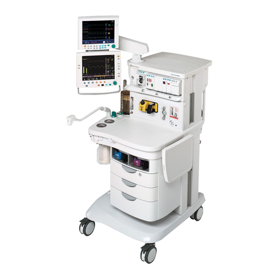
Page 20: Anesthesia System Components
Aisys 1.4 Anesthesia system components 1. Airway module (optional) 2. Datex-Ohmeda patient monitoring modules (optional) 3. Dovetail rails 4. Light switch 5. Alternate O control 6. Mains indicator 7. Brake 8. Aladin cassette storage bay 9. O flush button 10. System switch 11. - Page 21 1 Introduction 1. Display Unit system interface connections (refer to Section 2.5.1) 2. Collection bottle connection (optional) 3. Cylinder wrench (key) storage 4. Cylinder yoke 5. AGSS (Anesthesia Gas Scavenging System) 6. Pipeline connections 7. Mains inlet 8. System circuit breaker 9.
-
Page 22: Breathing System Components
Aisys 1.5 Breathing system components 1. Expiratory check valve 2. Inspiratory check valve 3. Inspiratory flow sensor 4. Expiratory flow sensor 5. Absorber canister 6. Absorber canister release 7. Leak test plug 8. Manual bag port 9. Breathing system release 10. -
Page 23: Optional System Components
1 Introduction 1.5.1 Optional system components 1. Bag support arm 2. Auxiliary Common Gas Outlet (ACGO) switch 3. ACGO port 4. EZchange Canister system (CO bypass) 5. EZchange Canister release 6. Condenser drain button 7. Condenser Figure 1-5 • Breathing system options M1046983 04/08... -
Page 24: Display Controls
Aisys 1.6 Display controls Alarm Silence key Push to silence any active, silenceable high and medium priority alarms or to suspend/acknowledge any non-active medium or high priority alarms. Alarm is silenced for 120 seconds or alarm is suspended for 90 seconds. Menu keys Push to show corresponding menu. -
Page 25: Anesthesia System Display
1 Introduction 1.7 Anesthesia system display 1. Electronic gas flow indicators 2. Alarm silence countdown 3. Alarm message fields 4. Waveform fields 5. General message field or timer field 6. Clock 7. Battery indicator field 8. Measured values field 9. Pipeline and cylinder supply or respiratory data 10. - Page 26 Aisys When a menu key is selected, the menu field overlays the gas flow tubes and the waveform fields start at the right edge of the menu. 1. Menu 2. Waveform fields Figure 1-8 • Menu view 1-10 04/08 M1046983...
-
Page 27: Using Menus
1 Introduction 1.7.1 Using menus Push a menu key to display the corresponding menu. Use the ComWheel to navigate through the menu. Xxxxxx Xxxxxx 1. Menu title 2. Present selection 3. Adjustment window 4. Indicates submenu 5. Short instructions 6. Menu selections Figure 1-9 •... -
Page 28: Symbols Used In The Manual Or On The Equipment
Aisys 1.8 Symbols used in the manual or on the equipment Symbols replace words on the equipment, on the display, or in Datex-Ohmeda manuals. No one device or manual uses all of the symbols. Warnings and Cautions tell you about dangerous conditions that can occur if you do not follow all instructions in this manual: •... - Page 29 1 Introduction Plus, positive polarity Movement in one direction Minus, negative polarity Movement in two directions Variability Read top of float Variability in steps Read to center of float Lamp, lighting, illumination Vacuum inlet This way up Suction bottle outlet Pipeline Cylinder Lock...
- Page 30 Aisys Vacuum Exhaust VACUUM Inspiratory flow Expiratory flow Inspiratory flow Expiratory flow Pinch hazard Submenu Circle breathing circuit module Bain/Mapleson D breathing circuit module The primary regulator is set to pressure The primary regulator is set to pressure < 345 kPa <...
- Page 31 1 Introduction Systems with this mark agree with the Indicates that the waste of electrical and European Council Directive (93/42/EEC) electronic equipment must not be for Medical Devices when they are used disposed as unsorted municipal waste as specified in their User’s Reference and must be collected separately.
- Page 32 Notes 1-16 04/08 M1046983...
-
Page 33: Theory Of Operation
2 Theory of Operation In this section 2.1 Electrical system ............2-2 2.2 Power subsystem . -
Page 34: Electrical System
Aisys 2.1 Electrical system The electrical system consists of two main computing units: the Display Unit and the Anesthesia Control board. Additional subsystems interact with these computing hosts to perform various gas delivery, ventilation, and monitoring functions. The Display Unit handles the main user interface functions and connections to external devices. - Page 35 2 Theory of Operation M1046983 04/08...
-
Page 36: Power Subsystem
Aisys 2.2 Power subsystem Mains power enters the system through the AC Inlet module (A), which includes a line filter and the system circuit breaker. Mains power is routed through the Inrush (B) board to the isolation transformer (C). The Inrush board protects against voltage spikes and conditions the AC mains. The isolated secondary output of the transformer (approximately 180 VAC) is routed through two, 5-amp fuses (D) to the universal power supply (E). -
Page 37: U-Frame Power Supply
2 Theory of Operation 2.2.1 U-Frame The power supply provides a regulated voltage of approximately 28 VDC input to the Power Power Supply Controller board. The supply has three electrical connections: • P1 is the 180 VAC inlet, • P2 is the output to the Power Controller board of approximately 28 VDC. -
Page 38: Power Distribution
Aisys 2.2.3 Power The Power Controller board provides outputs to the Anesthesia Control board and the Display Connector board. These boards provide distribution of power supplies required distribution by the system. The Anesthesia Control board interfaces with the Mixer board, the Ventilator Interface board, and the Agent Delivery board through the Pan Connector board. - Page 39 2 Theory of Operation 2.2.4 Power This board is a self-monitored and self-controlled by an on-board microcontroller. Much of its circuitry is used to monitor things like operating temperature of the board, Controller Board battery status, battery charging, and communication to the Display Unit. Its primary function is to distribute voltages to other subsystems and to keep the batteries charged.
- Page 40 Aisys The remaining LEDs are status indicators: • Battery Connected: is turned on and off by a time-delay circuit on the POWER CONTROLLER BOARD. Evidence of this is to disconnect AC Mains and place the unit in the Standby position. The fans will run for several seconds (on battery) until the battery is disconnected.
- Page 41 2 Theory of Operation The Power Controller board produces other voltages. • The 28 VDC that is generated by the U-Frame comes on the Power Controller board and is used to charge the machine batteries in one of three (3) modes. The charge voltage varies depending on the condition of the batteries. •...
-
Page 42: Display Unit
Aisys 2.3 Display Unit The Aisys anesthesia machine uses the High Performance Display Unit (HPDU). The Display Unit handles most of the machine’s user interface functions through the front panel controls and the LCD screen. It is the primary interface to external peripherals. -
Page 43: System Communications
2 Theory of Operation 2.4 System communications RS-422 serial communication is used between the two main processors — Display Unit and Anesthesia Computer — and the subsystem processors. Various baud rates accommodate data requirements between subsystem and host. External communication uses the standard RS-232 interface. M-Gas Ventilator Intel '196Processor... -
Page 44: Software Power On Self Tests (Post)
Aisys 2.4.1 Software Power On Self Tests (POST) When the machine is in the “Off” state, there is no machine activity. Circuitry on the Off State: Power Controller Board (PCB) and on the Anesthesia Control Board ACB) monitors the • AC Power is not On/Standby Switch for movement. - Page 45 2 Theory of Operation - The processor on the Agent Delivery Board performs standard CPU tests and establishes communications with the Anesthesia Control Board. The Anesthesia Control Board directs other POST activities including valve conditioning (full power for 15 seconds), reading and integrity checking of sensor calibration data, and reporting on serial number, hardware revision, and software revision.
-
Page 46: System Connections
Aisys 2.5 System connections 2.5.1 Display Unit The Display Unit accommodates the following connections: • System Power Interface (1). • System Signal Interface (2). • Serial Port — standard interface for external communication (3). • Remote monitor On/Standby (4). • Network connection — Standard Ethernet port for network connectivity (5). •... -
Page 47: Power Controller And Anesthesia Control Board Connections
2 Theory of Operation 2.6 Power Controller and Anesthesia Control board connections The Power Controller: • Distributes 12.5 VDC power and communicates with the Display Unit (by way of the Display Connector board) through connector (10). • Distributes 12.5 VDC power to the Anesthesia Control board through connector (14). The Anesthesia Control board: •... -
Page 48: Anesthesia Control Board
Aisys 2.7 Anesthesia Control board 2.7.1 Overview The Anesthesia Control board (A) uses a Motorola MCF5407 Coldfire microcontroller with 4M Flash and 16M error correcting DRAM. The Anesthesia Control board includes 6 UARTs with a 64 byte FIFO and RS-422 communications to interface with the Display Unit, an accessory port, and anesthesia delivery subsystems located in the pan electronic enclosure. - Page 49 2 Theory of Operation ON/Standby and Mains LED 12.5VDC Agent Delivery 10VA Power Vent +3.3V Supply Monitoring Bellow Sensor 12.5VDC 10VA Limit Mini AA Mixer Circuitry Accessory SW Test LEDs +1.8V Supply M-Gas Accessory 1 Backup Accessory 2 Audio and Sounder 12.5VDC +5V Supply...
-
Page 50: Anesthesia Control Board Details
Aisys 2.7.2 Anesthesia The 12.5 VDC power enters the Anesthesia Controller Board via connector J6 (see item 14 in Section 2.6). This 12.5 VDC is further regulated down to five additional Control Board voltages used by the Anesthesia Controller Board. These include: details •... - Page 51 2 Theory of Operation Power and The Anesthesia Controller Board provides power and communication to: Communication to other Subsystems Ventilator Interface Board (VIB): • Power = 12.5VDC • Communication = RS422 Gas Mixer: • Power = 12.5VDC • Communication = RS422 Agent Delivery Board (ADB): •...
- Page 52 Aisys External Peripheral This circuitry sends 10VA limited 12.5 VDC power to the following subsystems: power (10VA) circuitry Note:These subsystems do not receive power directly from the PCB. Only the Anesthesia Controller Board and Display Unit receive power directly form the PCB. •...
- Page 53 2 Theory of Operation Summary of the The Anesthesia Controller Board is the central controller for the system. It provides the Anesthesia Controller following services: Board • Monitors pressures form the pipeline and cylinder transducers. • Drives some of the valves located on the Electronic Gas Mixer. •...
-
Page 54: Ventilator Interface Board
Aisys 2.8 Ventilator Interface board The Ventilator Interface board (A) provides the electrical and/or pneumatic interface to the following: • Inspiratory (B) and expiratory (C) flow sensors (transducers) • Patient airway (D) and manifold (E) pressures (transducers) • Oxygen sensor (in breathing system) •... - Page 55 2 Theory of Operation +12.5V Accessory Power +12.5V Valve Power Exp Data +12.5V C MUX Insp Data to Flow Sensors +5.0VA Filter +5.0V +5.0VDD Local Power Reg. +12.5V +6.0VA Supply Bag/Vent Sw -6.0VA Regulators O2 Flush Sw Emulator Activity Indicators Header O2 Disconnect Reset, Watchdog,...
-
Page 56: Electronic Gas Mixer
Aisys 2.9 Electronic Gas Mixer The Gas Mixer receives its pneumatic inputs from the pipeline and cylinder supplies and sends mixed gas to the vaporizer manifold. The Gas Mixer interfaces to the Anesthesia Control board for power and communications. The Gas Mixer consists of the following subassemblies and main components: •... - Page 57 2 Theory of Operation Desired gas flows are sent from the Anesthesia Control board to the Gas Mixer. Gas Mixer operation is controlled through a microcontroller which: • Sends requests for the Anesthesia Control board to open and close selector valves for O and Air.
-
Page 58: Electronic Gas Mixer (Details)
Aisys 2.9.1 Electronic The function of the Electronic Gas Mixer is to deliver a combination of Oxygen and a Balance Gas (N O or Air) at a set percentage and flow rate as set by the user. Gas Mixer (details) Total flow range for the system is 0.20 to 15 l/min of O or mixed O concentration that... - Page 59 2 Theory of Operation As the system cycles through its self-tests, the six LEDs may cycle on and off throughout this process. It should also be observed the Valve 1 and Valve 2 LEDs cycle On and Off during Checkout. More detail on the timing and operation these valves will be covered later.
-
Page 60: Electronic Vaporizer
Aisys 2.10 Electronic Vaporizer The electronically controlled vaporizer consists of the internal electronic vaporization subsystem and the Aladin agent cassette. The agent cassettes are color coded, have indexed filling ports, and are magnetically coded for each agent. The electronic control unit governs the flow through the agent cassette and the agent concentration in the fresh gas flow. - Page 61 2 Theory of Operation 1. Handle with release trigger 2. Lock 3. Agent filling port 4. Liquid level indicator Figure 2-21 • Aladin desflurane cassette with Saf-T-Fil system 1. Handle with release trigger 2. Lock 3. Agent filling port 4. Liquid level indicator Figure 2-22 •...
-
Page 62: Electronic Vaporizer Subsystem (Evap)
Aisys 2.10.2 Electronic The Aisys system uses an integrated, electronic vaporization subsystem to add agent to the fresh gas flow. The main function of the Electronic Vaporizer subsystem is to mix the Vaporizer requested amount of anesthetic agent into the fresh gas stream. subsystem (eVap) Additional functions facilitated by the Electronic Vaporizer subsystem include cassette type detection, agent level detection, cassette overfill/overpressure handling, and... - Page 63 2 Theory of Operation Fresh Gas/ Agent Fresh Gas Backpressure (To CGO) (From Mixer) Regulator (Check valve) Relief Valve Manifold Inflow Outflow Temp Flowmeter Flowmeter Sensor Inflow Prop Check Valve Valve Liquid Inflow Check Valve Valve Key: Actuator Outflow Valve Sensor Sensor data Pneumatic flow...
- Page 64 Aisys RS422 Manifold I2C Bus Outflow Manifold ManTmp1 OFlwZVlv Zero Temp Valve Sensor ManTmp2 Board Inflow IFlwZVlv Zero Valve CassTmp1 Cassette Temp Sensor CassTmp2 Board Inflow IFlwVlv Valve Agent Delivery Board Outflow OFlwVlv Outflow Valve Pressure OutFlowDP Sensor Board Scavenge ScavVlv Valve Inflow...
- Page 65 2 Theory of Operation +12VP1 +12VP2 +12VP3 +12VP4 Outflow +12VP3 Zero Valve Manifold DGND Temp +12VFilt Sensor Board AGND Inflow +12VP3 Zero Valve DGND Cassette Temp Sensor Inflow +12VFilt +12VP3 Board AGND Valve Agent Delivery Board Outflow Outflow DGND +12VP2 Pressure Valve Sensor...
-
Page 66: Agent Delivery Board Led Indicators
Aisys 2.10.3 Agent Delivery board LED indicators LED indicators are provided on the Agent Delivery Board to convey information about subsystem operation. Refer to the following table and to Figure 2-26. Item Marking Indicates Color Blinks if microcontroller active Yellow Blinks if subsystem sending to Anesthesia Control Board Yellow Blinks if subsystem receiving from Anesthesia Control Board... - Page 67 2 Theory of Operation Figure 2-26 • Agent Delivery board LED indicators M1046983 04/08 2-35...
-
Page 68: Gas Flow Through The Anesthesia Machine
Aisys 2.11 Gas flow through the anesthesia machine 2.11.1 Overview Refer to Figure 2-27 and Figure 2-28. Gas supplies Gas comes into the system through a pipeline (1) or cylinder (6) connection. All connections have indexed fittings, filters, and check valves (one-way valves). Pressure transducers monitor the pipeline (2) and cylinder (7) pressures. - Page 69 2 Theory of Operation A - Pipeline Manifold B - Cylinder Supply C - Electronic Gas Mixer D - Electronic Vaporizer E - SCGO Assembly F - ACGO Assembly P - Pressure Transducer Cassette S - To Scavenging Figure 2-27 • Pneumatic circuit M1046983 04/08 2-37...
-
Page 70: Electronic Vaporizer
Aisys 2.11.2 Electronic Agent is delivered from the subsystem in one of two configurations depending on whether cassette pressure is below or above Mixer output pressure. If cassette vaporizer pressure is above Mixer output pressure, all fresh gas is routed through the Backpressure Regulator and agent is metered out of the pressurized cassette. - Page 71 2 Theory of Operation Electronic Vaporizer Mixed SCGO/ACGO Manifold Temp Sensor Scavenging Cassette ID Temp Sense Liquid Level Sense Figure 2-28 • Electronic vaporizer circuit M1046983 04/08 2-39...
- Page 72 Aisys A - Pipeline Manifold B - Cylinder Supply C - Electronic Gas Mixer D - Electronic Vaporizer E - SCGO Assembly F - ACGO Assembly P - Pressure Transducer Cassette S - To Scavenging Figure 2-29 • Pneumatic circuit 2-40 04/08 M1046983...
- Page 73 2 Theory of Operation Refer to Figure 2-29. Key to Numbered 1. Pipeline inlet Components 2. Pipeline pressure transducer 3. High-pressure relief valve (758 kPa / 110 psi)* 4. Supply connections for the ventilator and pilot pressure for SCGO a. O drive gas b.
-
Page 74: Physical Connections (O 2 Supply)
Aisys 2.11.3 Physical Figure 2-30 shows the physical path that the O gas supply takes. The item connections numbers are described in Figure 2-29. supply) ACGO Port 3 SCGO Port 2 Port 3 Pilot Mixer Balance Gas Flow Flow Disable Select Select Select... -
Page 75: Physical Connections (N2O And Air Supplies)
2 Theory of Operation 2.11.4 Physical Figure 2-31 shows the physical path that the N O and Air gas supplies take. connections The item numbers are described in (N2O and Air Figure 2-29. supplies) ACGO Port 3 eVap SCGO Port 2 Port 3 Pilot Mixer... -
Page 76: Suction Regulators
Aisys 2.11.5 Suction Pipeline vacuum regulators The suction regulator (shown in Figure 2-30) uses an external vacuum source. Venturi Drive vacuum The suction regulator (shown in Figure 2-32) uses an internal, venturi derived vacuum source. Drive gas (internally plumbed Air or O ) enters the Venturi Module (VM) at the drive port (A). -
Page 77: Flow Through The Breathing System
2 Theory of Operation 2.12 Flow through the breathing system 2.12.1 Overview of This section looks at four types of flow paths. flow paths • Ventilation paths: How gas flows from the drive source (bag or bellows) to and from the patient. -
Page 78: Manual Ventilation
Aisys 2.12.2 Manual ventilation Manual inspiration The Bag/Vent switch closes the ventilator path (B)..Gas flows from the bag (1), through the absorber (2), into the breathing circuit module, and through a unidirectional valve (inspiratory check valve) to the patient (3). During inspiration, fresh gas (FG) flows from the machine into the inspiratory limb, upstream of the inspiratory check valve. - Page 79 2 Theory of Operation Manual expiration The Bag/Vent switch keeps the ventilator path closed (B). Gas flows from the patient (4), through a unidirectional valve (expiratory check valve), and into the bag (5). During exhalation, fresh gas flows backwards through the absorber (FG) into the expiratory limb, downstream of the expiratory check valve.
- Page 80 Aisys APL Valve The APL valve sets a pressure limit for manual ventilation. As you turn the APL knob, it puts more or less force on the APL disc and seat (D/S). If the circuit pressure is too high (6), the disc and seat inside the diaphragm opens and vents gas to the scavenging system (7).
-
Page 81: Mechanical Ventilation
2 Theory of Operation 2.12.3 Mechanical ventilation Mechanical inspiration The Bag/Vent switch closes the manual path (V). Pilot pressure (P) closes the exhalation valve. Drive gas (D) pushes down on the bellows. Gas flows from the bellows (1), through the absorber (2), and through a unidirectional valve (inspiratory check valve) to the patient (3). - Page 82 Aisys Mechanical expiration Drive-gas flow stops and the exhalation valve opens. Exhaled gas flows from the patient (4), through a unidirectional valve (expiratory check valve) and into the bellows (5). Residual drive gas (D) flows out of the bellows to the scavenging system (6). If PEEP is selected, static pressure on the pilot port of the exhalation valve sets the PEEP level.
- Page 83 2 Theory of Operation Mechanical inspiration The Bag/Vent switch closes the manual path (V). Pilot pressure (P) closes the (EZchange and exhalation valve. condenser Drive gas (D) pushes down on the bellows. Gas flows from the bellows (1), through the absorber (2a), Condenser (2b), and through a unidirectional valve (inspiratory check valve) to the patient (3).
- Page 84 Aisys Mechanical expiration Drive-gas flow stops and the exhalation valve opens. Exhaled gas flows from the (EZchange and patient (4), through a unidirectional valve (expiratory check valve) and into the bellows (5). Residual drive gas (D) flows out of the bellows to the scavenging system (6). condenser If PEEP is selected, static pressure on the pilot port of the exhalation valve sets the PEEP level.
- Page 85 2 Theory of Operation Mechanical inspiration The Bag/Vent switch closes the manual path (V). Pilot pressure (P) closes the (EZchange and exhalation valve. condenser Drive gas (D) pushes down on the bellows. Gas flows from the bellows (1), through the OFF) EZchange module bypassing the absorber (2), and through a unidirectional valve (inspiratory check valve) to the patient (3).
- Page 86 Aisys Mechanical expiration Drive-gas flow stops and the exhalation valve opens. Exhaled gas flows from the (EZchange and patient (4), through a unidirectional valve (expiratory check valve) and into the bellows (5). Residual drive gas (D) flows out of the bellows to the scavenging system (6). condenser OFF) If PEEP is selected, static pressure on the pilot port of the exhalation valve sets the...
- Page 87 2 Theory of Operation Pop-off valve The pop-off valve limits the pressure inside the bellows to 2.5 cm H O above the drive gas pressure. This normally occurs when the bellows reaches the top of the housing at the end of exhalation (5). Excess gas (6) vents to the scavenging system (7) through the pop-off valve and the exhalation valve.
-
Page 88: Fresh Gas And O 2 Flush Flow (With Scgo)
Aisys 2.12.4 Fresh gas and O flush flow (with SCGO) To ABS (Circle) Fresh gas (1) flows from the electronic vaporizer (EV) to the SCGO assembly. breathing system With the Circle system selected, fresh gas flow is channeled to Port 3 of the breathing system (before the inspiratory check valve). - Page 89 2 Theory of Operation Switched (Non-circle) Fresh gas (1) flows from the electronic vaporizer (EV) to the SCGO assembly. Common Gas Outlet With the Non-Circle system selected, fresh gas flow is channeled to Port 2 of the breathing system (after the inspiratory check valve - to an external patient circuit through the Inspiratory port).
-
Page 90: Flush Flow (With Acgo)
Aisys 2.12.5 Fresh gas and O flush flow (with ACGO) To ABS (Circle) Fresh gas (1) flows from the electronic vaporizer (EV) to the ACGO Selector Switch. breathing system With the ACGO Selector Switch in the ABS position, fresh gas flow is channeled to the breathing system through port 3. - Page 91 2 Theory of Operation Auxiliary (Non-circle) Fresh gas (1) flows from the electronic vaporizer (EV) to the ACGO Selector Switch. Common Gas Outlet With the ACGO Selector Switch in the ACGO position, fresh gas flow is channeled to the ACGO outlet. At the ACGO outlet, a small sample is diverted to the O Cell in the ABS for O monitoring.
-
Page 92: Ventilator Mechanical Subsystems
Aisys 2.13 Ventilator mechanical subsystems Refer to Figure 11-1, "System circuit diagram" in Section11, for the complete pneumatic/mechanical subsystem diagram. The mechanical subsystems for the ventilator include: Pneumatic Vent Engine • Drive gas inlet filter • Gas inlet valve • Supply gas pressure regulator •... -
Page 93: Pressure Regulator
2 Theory of Operation 2.13.2 Pressure The pressure regulator (4) is a non-relieving pressure regulator that regulates high pressure filtered supply gas down to 172 kPa (25 psi). regulator (2.0 cm (3.5 cm H2O bias) Inspiratory Flow Control Valve 25 psig @ 15 LPM Gas Inlet Valve... -
Page 94: Drive Gas Check Valve (Dgcv)
Aisys 2.13.4 Drive Gas The Drive Gas Check Valve (6) is used downstream of the flow control valve to create the pilot pressure for closing the exhalation valve during inspiratory phases. The DGCV Check Valve is biased shut by an integral weight that supplies approximately 3.5 cm H O of bias (DGCV) pressure before permitting flow downstream to the bellows assembly. -
Page 95: Exhalation Valve
2 Theory of Operation 2.13.6 Exhalation The exhalation valve contains an elastomeric diaphragm that is used along with the flow valve to control the pressures in the breathing circuit. The exhalation valve valve includes two male ports on the bottom for: •... -
Page 96: Mechanical Overpressure Valve
Aisys 2.13.7 Mechanical The Mechanical Overpressure Valve (MOPV) is a mechanical valve (14) that operates regardless of electrical power. It functions as a third level of redundancy to the Overpressure Valve ventilator's pressure limit control functions, supplying pressure relief at approximately 110 cm H Vent Engine Atmosphere... -
Page 97: Free Breathing Valve
2 Theory of Operation 2.13.9 Free The free breathing valve (17) helps assure the patient can spontaneously breathe. The ventilator is programmed to supply a specified number of breaths per minute to the breathing valve patient. If, in between one of these programmed cycles, the patient needs a breath (spontaneous), the free breathing valve permits the patient to inhale. -
Page 98: Breathing Circuit Flow Sensors
Aisys 2.13.10 Breathing Two flow sensors are used to monitor inspiratory and expiratory gas flow: circuit flow • The inspiratory flow sensor is downstream of the breathing system inspiratory check sensors valve. • The expiratory flow sensor is located at the input to the breathin system expiratory check valve. -
Page 99: Checkout Procedure
3 Checkout Procedure In this section 3.1 Inspect the system ............3-2 3.2 System checkout . -
Page 100: Inspect The System
Aisys 3.1 Inspect the system w w w w CAUTION The upper shelf weight limit is 45 kg (100 lb). w w w w WARNING Do not leave gas cylinder valves open if the pipeline supply is in use. Cylinder supplies could be depleted, leaving an insufficient reserve supply in case of pipeline failure Before testing the system, ensure that: •... -
Page 101: Machine Check
3 Checkout Procedure 3.2.2 Machine Check The machine check runs automatically and beeps to indicate when it is finished or if interaction is required. The Machine Check does a: • Machine Check - System check (Ventilator Circuit), • Machine Check- Circuit check (Bag Circuit), •... -
Page 102: Machine Check - Circuit O2
Aisys 3.2.5 Machine Check - The Machine Check-Circuit O2 check measures the O Circuit O2 1. Open the patient Y. 2. Set the Bag/Vent switch to Vent. 3. (ACGO option only.) Set the ACGO switch to Circle. 4. The display will show the O %. -
Page 103: Circuit
3 Checkout Procedure 3.3.2 Circuit The Circuit check checks the Bag/Vent switch, proper gas supply pressures, airway pressure measurement transducer, APL valve, and manual circuit leak. Note: This check is performed during the "System Check" of the "System Checkout." 1. Occlude the patient Y. 2. -
Page 104: Low P Leak (Machines With Acgo)
Aisys 3.3.5 Low P Leak The negative low P leak check measures machine leaks before the breathing system and between the gas mixer and the common gas outlet. (machines with ACGO) Note: This check is NOT performed during the "System Check." This test is used to aid in troubleshooting if the "System Check"... -
Page 105: Bellows Drop Test
3 Checkout Procedure 3.4 Bellows drop test Note: This check is NOT performed during the "System Check." This test is used to aid in troubleshooting if the "System Check" fails. 1. End a case. 2. Set the Bag/Vent switch to Vent. 3. -
Page 106: Pipeline And Cylinder Tests
Aisys 3.6 Pipeline and cylinder tests 1. Connect the pipeline supplies one at a time and ensure that the corresponding display indicates pipeline pressure. 2. Disconnect all pipeline supplies. a. Open each cylinder valve. b. Make sure that each cylinder has sufficient pressure. If not, close the applicable cylinder valve and install a full cylinder. -
Page 107: Flush Flow Test
3 Checkout Procedure 3.7 Flush Flow Test 1. With Bag/Vent switch in Bag, verify case has ended. 2. Set the Bag/Vent switch to Vent. 3. Attach a patient circuit and plug the patient port. 4. For ACGO equipped machines, set the ACGO selector switch to Circle. 5. -
Page 108: Alarm Tests
Aisys 3.8 Alarm tests 1. Connect a test lung to the patient connection. 2. Start a case. 3. Set the Bag/Vent switch to Vent. 4. Set the O concentration to 30%, and allow the O reading to stabilize. • For machines configured to individual gas control, set O flow to approximately 500 ml/min and Air flow to approximately 5 l/min. -
Page 109: Alternate O2 Flowmeter Tests
3 Checkout Procedure 3.9 Alternate O flowmeter tests 1. Open the O cylinder valve or connect an O pipeline. 2. Rotate the Alt O flow control fully clockwise to minimum flow. 3. Press the Alternate O switch to turn on Alternate O flow. -
Page 110: Power Failure Test
Aisys 3.12 Power failure test 1. Connect the power cord to a wall outlet. The mains indicator on the front panel comes on when AC Power is connected. 2. Set the system switch to On and Start a case. 3. Unplug the power cord with the system turned on. 4. -
Page 111: Install/Service Menus
4 Install/Service Menus In this section 4.1 Service and Installation menu structure ........4-2 4.2 Install/Service Menu (Super User) . -
Page 112: Service And Installation Menu Structure
Aisys 4.1 Service and Installation menu structure This section describes the Service level functions that are part of the main software installed in the anesthesia machine. Section 8, “Software Download and Special Functions,” covers the functions of the Compact Flash card used to download system software. Section 12, “Service Application,”... -
Page 113: Install/Service Menu (Super User)
4 Install/Service Menus 4.2 Install/Service Menu (Super User) Use the super-user password to access the Install/Service menu: “16-4-34.” Install/Service - Page 1 Menu Item Message text Comments Trends Setup Configure graphical trend pages. Colors and Units Set colors and units of parameters. Refer to section 4.2.1 Cumulative Gas Usage View total usage of fresh gases since... - Page 114 Aisys Install/Service - Page 2 Menu Item Message text Comments Fresh Gas Controls Select style for Fresh Gas Controls: Default is O2%. O2 and Total Flow or Individual Gas Flows. VCV Cardiac Bypass Allow machine breaths during Default is No. cardiac bypass.
-
Page 115: Trends Setup
4 Install/Service Menus 4.2.1 Trends Setup Menu Item Message text Values Default Trend Change default trend type: Num (default), graphical, numerical, or settings. Graph, or Set Graphical Trends Configure graphical trend pages. Previous Menu Return to previous menu. Graphical Trends Menu Item Message text Values... -
Page 116: Colors And Units Menu
Aisys 4.2.2 Colors and Units The Units menu can be accessed here in the super-user level to change individual preferences, or if required during installation, in the service level Menu Installation menu. Menu Item Message text Values Colors Set colors of parameters. Weight Change weight unit: kg or lb. -
Page 117: Cumulative Usage
4 Install/Service Menus 4.2.3 Cumulative Usage Gas and agent cumulative usage data is store in non-volatile RAM. Menu Item Message text Values Reset Usage Push ComWheel to set cumulative Date of last reset. fresh gas totals to zero. Desflurane Enflurane Halothane Isoflurane Sevoflurane... -
Page 118: Factory Defaults
Aisys 4.2.4 Factory Defaults The following table lists the factory defaults for parameters. The table on the next page lists the factory defaults for alarm limits. Factory defaults — Parameters Parameter Value Parameter Value Vent Mode CO2 Units TV (tidal volume) 500 ml Altitude 300 m... - Page 119 4 Install/Service Menus Factory defaults — Alarm limits Alarm Limit Value Pmax High 40 cmH2O (40 hPa, 4 kPa, 40 mbar, 30 mmHg) MV High 10 l/min MV Low 2 l/min TV High 1000 ml TV Low RR High RR Low Et CO2 High 8.0% (60 mmHg or 8.0 kPa)
-
Page 120: Parameter Settings
Aisys 4.2.5 Parameter Settings Menu Item Message text Values TV Based on Change volume calculation ATPD - default conditions: ATPD or BTPS. (Ambient temperature and pressure, dry humidity condition) BTPS (Body temperature, ambient pressure, saturated humidity condition) CO2 Numbers Change humidity compensation type Dry - default in CO2 partial pressure values. -
Page 121: Installation Menu
4 Install/Service Menus 4.3 Installation Menu Use the service-level password to access the Installation menu: “26-23-8.” Whenever the installation menu is entered, “Enter Service dd-mmm-yyyy hh:mm:ss” is recorded in the Event log. Menu Item Message text Configuration Set language, gas color code, O2 flowmeter position. Units Set units. -
Page 122: Configuration
Aisys 4.3.1 Configuration Menu Item Message text Values Comments Decimal Marker Select decimal 0.01, 0 01 or 0,01 delineator. Language Change language Chinese (simplified) Default: English translation of screen Czech texts. Danish Dutch English Finnish French German Greek Hungarian Italian Japanese Norwegian Polish... -
Page 123: Configuration Units
4 Install/Service Menus 4.3.2 Configuration Units This is the same menu that is accessible from the super-user Install/Service menu. Menu Item Message text Values Weight Change weight unit: kg or lb. kg or lb Change CO2 unit: %, kPa, or mmHg. %, kPa, or mmHg Gas Supply Pressure... -
Page 124: Copy Configuration
Aisys Options List menu The options list shows which options are enabled. Menu Item Message text Values * Available Options SIMV/PSV SIMV vent w/pressure support. On, Off Pressure controlled ventilation. On, Off PSV Pro Pressure support ventilation w/backup. On, Off PCV-VG Pressure controlled volume guaranteed On, Off... -
Page 125: Service Menu
4 Install/Service Menus 4.4 Service Menu Use the service-level password to access the Service menu: “26-23-8.” Whenever service menu is entered, “Enter Service dd-mmm-yyyy hh:mm:ss” is recorded in the Event log. Menu Item Message text SW HW versions Scroll through system information. Service Log Show error, event, and alarm histories. -
Page 126: Software/Hardware Ver Menu
Aisys 4.4.1 Software/ Turn the ComWheel to scroll through the list box. Hardware Ver Menu Push the ComWheel to return to the Service menu. System Information menu List box text with X=Number, A, B, C = letter Total Time: XXXXX (Minutes) Software Release: XX.XX Model Code: XXX Machine Serial Number: ABCDXXXXX... -
Page 127: Service Log Menu
4 Install/Service Menus 4.4.2 Service Log Menu The Service log menu is an organized listing of stored events. Menu Item Message text Scroll Recent Scroll through newest entries. Error History Show error history. Event History Show event history. Alarm History Show alarm history. -
Page 128: Calibration
Aisys 4.5 Calibration For step-by-step instruction, refer to Section 5.4, “Ventilator Calibrations.” Menu Item Message text Instructions These values are used for calibration: Ventilator drive gas - Air or O2 Altitude - XXXX m Change these values on the Cal Config menu Spiro Calibration Check gas module spirometry gains. -
Page 129: Spiro Calibration
4 Install/Service Menus 4.5.1 Spiro Calibration The Spiro Calibration instructions appear when the focus is on Spiro Calibration menu item. Instructions To display TV data: 1. Connect a spirometry sensor to MGas. 2. Push the ComWheel to continue. 3. Select the correct spirometry sensor type (Adult or Pedi). 4. -
Page 130: User Calibration Menu
Aisys 4.5.2 User Calibration menu Menu Item Message text Flow and Pressure Calibrate the flow and pressure sensors. Remove flow sensor module to start. Replace when Pass or Fail message appears. Circuit O2 Cell Calibrate Circuit O2 Cell. 21% O2 Remove Flow Sensor Module. -
Page 131: Manifold P Span
4 Install/Service Menus 4.5.3 Manifold P Span The Manifold P Span instructions appear when the focus is on Manifold P Span menu item. Instructions Read all steps before you start: 1. Remove the breathing system, the exhalation valve, and the metal plate. 2. -
Page 132: Insp Flow Zero
Aisys 4.5.4 Insp Flow Zero Note: Not required for machines with System Software 4.X or greater. The Insp Flow Zero instructions appear when the focus is on the Insp Flow Zero menu item. Refer to Section 5.4.4, “Insp Flow Zero.” Instructions Read all steps before you start: 1. -
Page 133: Inspiratory Flow Valve
4 Install/Service Menus 4.5.5 Inspiratory Flow The Inspiratory Flow Valve instructions appear when the focus is on the Insp Flow Valve menu item. Valve Refer to Section 5.4.3, “Inspiratory Flow Valve Cal.” Instructions Read all steps before you start: 1. Complete the Manifold P Span calibration. 2. -
Page 134: Bleed Resistor
Aisys 4.5.6 Bleed Resistor The Bleed Resistor instructions appear when the focus is on the Bleed Resistor menu item. Refer to Section 5.4.5, “Bleed Resistor Cal.” Instructions Read all steps before you start: 1. Complete the Insp Flow Valve calibration. 2. -
Page 135: Paw Span
4 Install/Service Menus 4.5.7 Paw Span The Airway P Span instructions appear when the focus is on Paw Span menu item. Refer to Section 5.4.6, “Paw Span.” Instructions Read all steps before you start: 1. Complete the Bleed Resistor calibration. 2. -
Page 136: Zero Gas Xducrs
Aisys 4.5.8 Zero Gas Xducrs The Zero Gas Xducers instructions appear when the focus is on the Zero Gas Xducer menu item. Instructions Read all steps before you start: 1. Remove all cylinders. 2. Disconnect all pipeline supplies. 3. Select Zero Gas Xducrs. 4. -
Page 137: Cal Config
4 Install/Service Menus 4.5.9 Cal Config Before calibration, you must verify that the Ventilator Drive Gas and the Altitude settings are set appropriately to match the current drive gas configuration and machine location. If you change any of the settings in the Cal Config menu, you must restart the system. -
Page 138: Mixer P Zero
Aisys 4.5.10 Mixer P Zero The Mixer P Zero instructions appear on the Mixer P Zero menu. Instructions Back Default Start To go back to factory defaults, select Defaults (above). To Zero Pres Sensors: 1. Disconnect pipeline gas supplies. 2. Close the gas cylinders. 3. -
Page 139: Calibration
5 Calibration WARNING After adjustments and calibration are completed, always perform the checkout procedure. Refer to Section 3 of this manual. In this section 5.1 Primary Regulators ............5-2 5.1.1 Test setup . -
Page 140: Primary Regulators
Aisys 5.1 Primary Regulators First, follow the procedure in Section 5.1.1 to gain access to the regulators. Then, in Section 5.1.2, select the test that is appropriate for the regulator you are testing. w w w w WARNING When testing/adjusting N O regulators, nitrous oxide flows through the system. -
Page 141: Test Setup
5 Calibration 5.1.1 Test setup w w w w WARNING Wear safety glasses while test device is connected to the test port. w w w w CAUTION Be careful not to plug the output of the primary regulator without having a pressure relief valve in the output circuit. - Page 142 Aisys Test A For primary regulators that supply drive gas to the ventilator (O or Air): Under low flow conditions, the output pressure of a properly adjusted/ functioning regulator should fall within specifications listed in step 5d. Under high flow conditions, the output pressure should not drop below the specifications listed in step 6f.
- Page 143 5 Calibration 6. High Flow Test: a. Slowly open the cylinder valve. b. Remove the ABS breathing system from the machine to allow continuous Insp Valve flow through the exhalation valve. c. Access the Ventilation Schematic (Section 12.3.3) of the Service Application.
- Page 144 Aisys Test B For all gases not used to supply drive gas to the ventilator: Under low flow conditions, the output pressure of a properly adjusted/ functioning regulator should fall within specifications listed in step 5d. Under high flow conditions, the output pressure should not drop below the specifications in step 6a.
- Page 145 5 Calibration 6. High Flow Test: a. Access the Gas Delivery Schematic. b. Open the cylinder valve for the regulator being tested. c. Set Total Flow of the tested gas to 10 l/min. The test device reading must be greater than: ( ( ( ( 6 6 6 6 0 0 0 0 ) ) ) ) D D D D I I I I N N N N 221 kPa (32 psi) ( ( ( ( 5 5 5 5 0 0 0 0 ) ) ) ) P P P P i i i i n n n n I I I I n n n n d d d d e e e e x x x x e e e e d d d d 221 kPa (32 psi) - If the test device reading under “high flow”...
-
Page 146: Adjusting Primary Regulators
Aisys 5.1.3 Adjusting Primary Important: Cylinder supplies in an Aisys machine must have all primary regulators set to the same pressure range: Regulators (50) Pin Indexed or (60) DIN. If a regulator is replaced, the replacement regulator must be set (as required) to the same specification as the one removed. -
Page 147: Flush Regulator
5 Calibration 5.2 O Flush Regulator 1. Bleed all gas pressure for the machine (Section 9.2). 2. Remove the tabletop (Section 9.4). 3. Remove the cover from the electronic enclosure. 4. Remove the O Flush Regulator output tubing. Attach a 6-mm tee and a test device to the open port. -
Page 148: Adjust Drive Gas Regulator
Aisys 5.3 Adjust Drive Gas Regulator The drive gas regulator must be adjusted while maintaining a flow of 15 l/min. To adjust the flow, you must set the system to the Install/Service mode and use the PC based Service Application to control flow through the regulator. -
Page 149: Ventilator Calibrations
5 Calibration 5.4 Ventilator Calibrations Before performing the ventilator calibrations, verify that the drive gas regulator is adjusted to specifications (Section 5.3). The Service menu structure is detailed in Section 4. To access the Ventilator Calibrations menu: 1. Turn on the system. 2. -
Page 150: Cal Config
Aisys 5.4.1 Cal Config Before calibration, you must verify that the Ventilator Drive Gas and the Altitude settings are set appropriately to match the current drive gas configuration and machine location. If you change any of the settings in the Cal Config menu, you must restart the system. -
Page 151: Manifold P Span
5 Calibration 5.4.2 Manifold P Span Calibration setup: 1. Remove the ABS breathing system from the machine. 2. Remove the Exhalation Valve. 3. Remove the Vent Engine cover. 4. Plug the Drive Port (A) and the Manifold Port (B) on the Vent Engine interface valve. -
Page 152: Inspiratory Flow Valve Cal
Aisys 5.4.3 Inspiratory Flow Valve Cal Calibration setup Leave the Drive Port (A) and the Manifold Port (B) on the interface valve plugged. Calibration procedure: 1. On the Calibration menu, select Insp Flow Valve. 2. Push the ComWheel to enable the Stage 1 calibration. 3. - Page 153 5 Calibration Troubleshooting Stage 2 Calibration Failures The Calibration will fail if the: • Flow valve DAC reaches 4095 before determining the Lift-Off Point. • Previously found DAC value is ≥ to the current DAC value while finding points 7 through 24. •...
-
Page 154: Insp Flow Zero
Aisys 5.4.4 Insp Flow Zero Note: Not required for machines with System Software 4.X or greater. Calibration setup 1. Remove the Calibration Orifice from the Manifold port. 2. Plug the Manifold (B) port. 3. Leave the Drive Gas (A) port plugged. Calibration procedure: 1. -
Page 155: Bleed Resistor Cal
5 Calibration 5.4.5 Bleed Resistor Cal Calibration setup Leave the Drive Port (A) and the Manifold Port (B) on the interface valve plugged. Calibration procedure 1. On the Calibration menu, select Bleed Resistor. 2. Select Start. 3. When the test is completed, select Previous Menu. Troubleshooting Bleed Resistor Calibration Failures The Calibration will fail if the:... -
Page 156: Paw Span
Aisys 5.4.6 Paw Span Calibration setup 1. Leave the Drive port (A) port plugged. 2. Remove the plug from the Manifold port. 3. Attach a patient circuit tube to the Calibrated Flow Orifice. 4. Insert the Calibrated Flow Orifice into the Manifold port (B). 5. - Page 157 5 Calibration Troubleshooting Paw Span Calibration Failure The Calibration will fail if the: • ADC value calculated for span is outside the range of 21000-27000 counts. Possible causes for calibration failure: • Occlusion or moisture in bulkhead or tubing to VIB transducers. •...
- Page 158 Notes 5-20 04/08 M1046983...
-
Page 159: Installation And Maintenance
6 Installation and Maintenance In this section This section covers the regular maintenance procedures (minimum requirements) needed to make sure that the Aisys anesthesia machine operates to specifications. 6.1 Aisys Installation Checklist ...........6-2 6.2 Aisys Planned Maintenance . -
Page 160: Aisys Installation Checklist
Aisys 6.1 Aisys Installation Checklist Serial Number: Date: (YY/MM/DD) Hospital: Performed by: 1. Unpack and assemble the Aisys System. 2. Reconfigure the sample gas return line as required (TRM - Section 9.23). 3. Access the Installation menu from the Install/Service menu and change the following as required: a. - Page 161 6 Installation and Maintenance 4. Verify the “Schedule Service Calibration” message is not present in the normal display. 5. Complete the System Checkout by performing the following steps: a. Inspect the system (TRM - Section 3.1) b. System checkout (TRM - Section 3.2) Note: You must insert a Test Cassette for the Machine Check - System Agent Delivery Test to run the extended diagnostic Vaporizer Test.
-
Page 162: Aisys Planned Maintenance
Aisys 6.2 Aisys Planned Maintenance Serial Number: Date: (YY/MM/DD) Hospital: Performed by: 12 months 24 month 48 month ______________________ 6.2.1 Every twelve Perform the following steps every 12 months. For details, refer to the sections listed. (12) months • Sections marked URM are found in the User’s Reference manuals for the Aisys anesthesia system. -
Page 163: Every Twenty-Four (24) Months
6 Installation and Maintenance 12. Perform the following diagnostics using the Compact Flash Special Functions. • Display Diagnostics (TRM - Section 8.3.1). 13. Perform the following diagnostics using the PC Service Application. • Vaporizer Test with a Test Cassette inserted (TRM - Section 12.10.2). •... -
Page 164: Free Breathing Valve Maintenance
Aisys 6.3 Free breathing valve maintenance Refer to section 9.13 to access the Pneumatic Vent Engine. 1. Unscrew the valve seat ( ) from the side of the interface manifold. 2. Inspect the flapper ( ) and valve seat for nicks, debris and cleanliness. To replace the flapper valve 3. -
Page 165: Mopv Pressure Relief Valve Test
6 Installation and Maintenance 6.4 MOPV pressure relief valve test WARNING Objects in the breathing system can stop gas flow to the patient. This can cause injury or death: • Do not use a test plug that is small enough to fall into the breathing system. -
Page 166: Pressure Limit Circuit Test
Aisys 6.5 Pressure Limit Circuit test To perform the test: • establish a closed patient airway circuit. • increment the pressure in the airway circuit. • observe the output of the airway pressure transducer. • note that the “pressure limit circuit” trips at approximately 109 cmH Test setup 1. - Page 167 6 Installation and Maintenance Test Procedure 10.Access the Ventilation Schematic (TRM - Section 12.3.3) of the Service Application. 11.Select Vent Status and verify that Over Pressure Circuit reads OK. 12.Select Gas Inlet Valve to ON. 13.Adjust the Insp Flow Valve counts to approximately 1000 counts and observe the Airway Pressure reading on the Ventilator Schematic.
-
Page 168: Mixer Test
Aisys 6.6 Mixer test To perform the mixer tests, you must gain access to the mixer outlet tubing which is connected to the inlet of the electronic vaporizer. 1. To access the electronic vaporizer, refer to Section 9.7 2. Disconnect the mixer outlet tube at the inlet to the electronic vaporizer. 6.6.1 Mixer outlet check valve leak test To test the mixer outlet check valve you must apply back pressure to the check valve through the mixer outlet tubing and time the leak down rate of the pressure. - Page 169 6 Installation and Maintenance 6.7 Alternate O flowmeter tests 1. Open the O cylinder valve or connect an O pipeline. 2. Rotate the Alt O flow control fully clockwise to minimum flow. 3. Press the Alternate O switch to turn on Alternate O flow.
-
Page 170: Auxiliary O2 Flowmeter Tests
Aisys 6.8 Auxiliary O flowmeter tests 1. Open the O cylinder valve or connect an O pipeline. 2. Rotate the flow control clockwise (decrease) to shut off the flow. The ball should rest at the bottom of the flow tube and not move. 3. -
Page 171: Integrated Suction Regulator Tests
6 Installation and Maintenance 6.9 Integrated Suction Regulator tests Note There are two types of integrated suction systems for the Avance anesthesia machine: • Continuous Vacuum Regulator, Three-Mode, Pipeline Vacuum • Continuous Vacuum Regulator, Three-Mode, Venturi Derived Vacuum For Pipeline Vacuum systems, a vacuum source of at least 500 mm Hg (67 kPa or 20 in Hg) is required for testing. - Page 172 Aisys Regulation Test 1. Turn the mode selector switch to I (ON). 2. Occlude the patient port of the suction regulator. 3. Set the vacuum regulator gauge to 100 mm Hg/13 kPa. 4. Open and close the patient port several times. 5.
-
Page 173: Battery Capacity Test
6 Installation and Maintenance 6.10 Battery capacity test Although replacement of the backup batteries is recommended at the end of 4 years, batteries that pass the capacity test can be considered viable for battery backup of the system for up to 6 years at the discretion of the hospital. Before testing the batteries, ensure that they are fully charged. -
Page 174: Cable Routing, Upper Module Rack
Aisys 6.11 Cable routing, upper module rack The following diagram shows typical cable connections for Aisys machines with an upper module rack. Refer to the individual sections showing proper routing of the cables through the machine. Note In general, route the cables through the machine as shown in the following sections. -
Page 175: Display Unit And Anesthesia Monitor
6 Installation and Maintenance 6.11.1 Display Unit and Anesthesia Monitor Attach the respective cables to the Display Unit ( and, if present, to the monitor ( Leave enough cable length outside the arm to allow positioning of the displays throughout the full range without straining the cables. -
Page 176: Left-Side Cable Route
Aisys 6.11.3 Left-side cable route To access the left-side cable route, remove the following: • the breathing system. • the upper left-side cosmetic panel. • the lower left-side cosmetic panel. • the AGSS reservoir. Route the cables through the cable clamps shown arrows 6.11.4 Upper left-side cable route The upper left-side is a transition route for cabling. -
Page 177: Upper Module Rack
6 Installation and Maintenance 6.11.6 Upper module rack To access the upper module rack, remove the upper rear cosmetic cover. Store the power supply “brick” ( for the 15-inch Anesthesia Monitor display and the DIS adapter ( ) in the open area to the right of the M-Gas power supply ( Coil the excess length of each cable and store it in the open area below... -
Page 178: Cable Routing, Lower Module Rack
Aisys 6.12 Cable routing, lower module rack The following diagram shows typical cable connections for Aisys machines with an lower module rack. Refer to the individual sections showing proper routing of the cables through the machine. Note In general, route the cables through the machine as shown in the following sections. Connect each end to the intended connector. -
Page 179: Display Unit And Anesthesia Monitor
6 Installation and Maintenance 6.12.1 Display Unit and Anesthesia Monitor Attach the respective cables to the Display Unit ( and, if present, to the monitor ( Leave enough cable length outside the arm to allow positioning of the displays throughout the full range without straining the cables. -
Page 180: Left-Side Cable Route
Aisys 6.12.3 Left-side cable route To access the left-side cable route, remove the following: • the breathing system. • the upper left-side cosmetic panel. • the lower left-side cosmetic panel. • the AGSS reservoir. Route the cables through the cable clamps shown ( arrows The upper left-side is a transition route for cabling: •... -
Page 181: Rear Cable Route
6 Installation and Maintenance 6.12.5 Rear cable route To access the rear cable route, remove the rear pneumatics cosmetic panel and the upper rear cosmetic cover. Route the cables through the cable clamps shown ( arrows Store the power supply “brick” ( ) for the 15-inch Anesthesia Monitor display in the open area to the right of the M-Gas power supply (... -
Page 182: Right-Side Cable Route
Aisys 6.12.6 Right-side cable route To access the cable route on the right side of the machine, remove the lower and upper right-side cosmetic panels. Route the cables through the cable clamps shown arrows Note: When replacing the lower cosmetic panel, position the cables within the beveled edge of the extrusion to allow a flush mount of the panel without pinching the cables... -
Page 183: Troubleshooting
7 Troubleshooting In this section 7.1 Troubleshooting Guidelines ..........7-2 7.2 Troubleshooting high pressure and low pressure leaks . -
Page 184: Troubleshooting Guidelines
Aisys 7.1 Troubleshooting Guidelines Review system error logs using the Service Log menu (Section 4.4.2) or download the logs to PC files using the PC Service Application (Section 12.6.3). Review the logs to identify issues and follow the appropriate subsystem troubleshooting procedures. Troubleshooting high pressure and low pressure leaks . -
Page 185: Troubleshooting High Pressure And Low Pressure Leaks
7 Troubleshooting 7.2 Troubleshooting high pressure and low pressure leaks Problem Possible Cause Action High Pressure Leak Pipeline leak Use a leak detector or Snoop to check for source of leak. Repair or replace defective parts. flush valve Use a leak detector or Snoop to check for source of leak. Make sure tubing connections are tight. -
Page 186: Troubleshooting Startup Screen (Post) Messages - For Hpdu
Aisys 7.3 Troubleshooting Startup Screen (POST) messages - for HPDU If the Aisys system encounters a problem at startup to where it cannot initiate system software, a BIOS error message indicating the failure will be displayed. Message What it indicates Troubleshooting Action Required ***ERROR: This indicates a hardware failure. -
Page 187: Troubleshooting The Hpdu Display
7 Troubleshooting 7.4 Troubleshooting the HPDU Display Symptom Resolution System will not boot from external Compact Flash 1. Verify that the Compact Flash card is properly inserted. card during software installation process 2. Insert a backup Compact Flash card. 3. Open the HPDU and verify that the external Compact Flash card carrier socket (1009-5961-000) is properly seated. -
Page 188: Troubleshooting System Malfunction (Safe-State) Screen
Aisys 7.5 Troubleshooting System Malfunction (safe-state) screen Machine logs • Compatibility incomplete: No versions received from Vent SIB • System Self-tests failed The above error log entries are due to the Ventilator failing its Power-On Self Test (Post). When the ventilator fails its self-test, the system enters the safe-state. The likely cause is a Gas Inlet Valve Solenoid that is not transitioning to the de-energized state when valve drive power is removed. -
Page 189: Breathing System Leak Test Guide
7 Troubleshooting 7.6 Breathing System Leak Test Guide Note Always do the System “Checkout” (Section 3.2) on the machine before proceeding with these breathing system leak tests. Follow the troubleshooting flowcharts in Section 7.6.2 to determine the best sequence of tests for locating a breathing system leak. The procedures in Section 7.6.3 test specific components of the breathing system for leaks. -
Page 190: Check Valves
Aisys 7.6.1 Check Make sure that the check valves on the breathing circuit module work correctly: The Inspiratory check valve rises during inspiration and falls at the start of expiration. The Valves Expiratory check valve rises during expiration and falls at the start of inspiration. A leak across one of the check valves may be great enough to cause a “reverse flow”... -
Page 191: Breathing System Troubleshooting Flowcharts
7 Troubleshooting 7.6.2 Breathing System Troubleshooting Flowcharts Start (Section 7.6) Review Leak Test Guide (Section 3.2) • Do System checkout • Isolate breathing system leak to Bag Mode,Vent Mode, or Both Perform Leak Test 1 Verifying the integrity of test tools Perform Test 2 Repair leak in Low-pressure leak... - Page 192 Aisys Leak in Bag Mode only Perform Test 4 Testing the bag port, Pass APL Valve, and Bag/Vent Switch, and Negative Pressure Relief Valve Re-Install all breathing circuit components and repeat Fail System checkout (Section 3.2) Check or Replace Does the the Bag/Vent Bellows Switch lower Seal...
- Page 193 7 Troubleshooting Leak in Vent Mode only Perform Test 6 Pass Testing the bellows assembly, and Bag/Vent Switch Perform Test 8 Inspect Exhalation Valve Testing the bellows and and Drive Circuit bellows Pop-off Fail Pass Re-Install all breathing circuit components and repeat System checkout (Section 3.2) Perform Test 7...
- Page 194 Aisys Leak in both Bag and Vent Mode Common Areas: Flow Sensor Module, Circuit Module, Soda Lime Canister, Negative Pressure Relief Perform Test 9 Testing the Flow Sensor Fail Pass Module, Circuit Module, and Soda Lime Canister Perform Test 13 Perform Test 10 Testing the Testing the Circuit...
- Page 195 7 Troubleshooting Leak in Flow Sensor Module or Circuit Module Perform Tests 14 and 15 Testing the Flow Sensors Fail Pass using the low-pressure leak test device Check/Replace Check/Replace the seals Flow Sensors or on the Circuit Module and bulkhead connector the O-Ring on the O cell O-Rings...
-
Page 196: Leak Isolation Tests
Aisys 7.6.3 Leak The previous flowcharts refer you to the following tests. Isolation Tests These tests require the use of the Low Pressure Leak Test Device and the Leak Test Tool Kit (refer to Section 10.1, "Service tools"). The Leak Test Tool Kit includes: •... - Page 197 7 Troubleshooting Test 1 Verifying the integrity of the test tools Machine Test Tool Front View Bulb Thru Port (not connected to airway path) Pressure Sense Port Fresh Gas Port Alignment Post Back View Bulb Thru Port Alignment Post 1. Verify integrity of low-pressure leak test device. •...
- Page 198 Aisys Test 2 Low-pressure leak testing the machine 1. Remove the breathing system from the machine. 2. Attach the Machine Test Tool (using only the Thru Port) and the low-pressure leak test device to Port 3 of the breathing system interface as shown above. Note: To prevent damage to the airway pressure transducer, ensure that the gauge port (Port 1) is not connected to the Test Tool.
- Page 199 7 Troubleshooting Test 3 Testing the airway pressure transducer, and Port 1 and Port 3 u-cup seals Alignment Post 1. Access the Gas Delivery Schematic (Section 12.3.2) of the Service Application. 2. Set O Flow to 0.1 l/min. 3. Attach the Machine Test Tool to the breathing system interface ports (using the alignment post) as shown above.
- Page 200 Aisys Test 4 Testing the bag port cover, the APL valve, the Bag/Vent switch, and the negative pressure relief valve Plug Bag Port 1. Separate the Bellows Module from the Circuit Module and re-install the Bellows Module. 2. Occlude the Bag Port connector. 3.
- Page 201 7 Troubleshooting Test 5 Testing the APL diaphragm Plug Scavenging Port Plug Bag Port Note If required, set up the Machine Test Tool and breathing system as shown in Test 4. 1. Slide the Bellows Module away from the machine. 2.
- Page 202 Aisys Test 6 Testing the bellows module and the Bag/Vent switch 1. Separate the Bellows Module from the Circuit Module and re-install the Bellows Module. 2. Connect the Machine Test Tool to the interface ports as shown above. 3. Set the Bag/Vent switch to the Vent position. 4.
- Page 203 7 Troubleshooting Test 7 Testing the bellows, the bellows pop-off valve, the bellows base manifold, and the Bag/Vent switch 1. Separate the Bellows Module from the Circuit Module. 2. Insert appropriate test plugs into the bellows base manifold as shown to the left.
- Page 204 Aisys Test 8 Testing the bellows assembly Note If required, set up the Machine Test Tool and breathing system as shown in Test 7. 1. Remove the bellows base manifold from the Bellows Module. 2. Insert appropriate test plugs into the bellows base manifold as shown to the left.
- Page 205 7 Troubleshooting Test 9 Testing the flow sensor module, the circuit module, and the soda lime canister Plug 1. Separate the Bellows Module from the Circuit Module and re-install the Circuit/Flow Sensor Module. 2. Connect short tubing between the inhalation and exhalation ports of the breathing system.
- Page 206 Aisys Test 10 Testing the circuit module and the canister 1. Remove the Flow Sensor module. 2. Connect the Circuit Test Tool to the Circuit Module as shown above. 3. Set O Flow to 0.2 l/min. • Ensure that the Airway Pressure rises to ≥ 30 cm H 4.
- Page 207 7 Troubleshooting Test 12 Testing the inspiratory side of the circuit module Plug Loop Note: If required, set up the machine as in Test 10 and 11. 1. Connect the Circuit Test Tool to the Circuit Module as shown above. 2.
- Page 208 Aisys Test 13 Testing the negative pressure relief valve 1. Separate the Bellows Module from the Circuit Module. 2. Remove the Bellows Interface Manifold. 3. Insert test plug (recessed end) into the rear Bag/Vent switch port as shown. Plug 4. Install the Bellows Module. 5.
- Page 209 7 Troubleshooting Test 14 Testing the flow sensors only Note: To ensure a air-tight seal, use the corresponding plug as illustrated for the original flow sensor ( A ) or the new, moisture resistant (offset) flow sensor ( B ). 1.
- Page 210 Aisys Test 15 Testing a flow sensor including the Ventilator Monitoring Assembly and interfacing components Note: To ensure a air-tight seal, use the corresponding plug as illustrated for the original flow sensor ( A ) or the new, moisture resistant (offset) flow sensor ( B ).
-
Page 211: System Troubleshooting Flowcharts
7 Troubleshooting 7.7 System Troubleshooting Flowcharts Legend: ACB = Anesthesia Control Board PCB = Power Controller Board Start VIB = Ventilator Interface Board Turn on System DU = Display Unit GIV = Gas Inlet Valve APL = Adjustable Pressure Limit Does the System Application Proceed to "Display Screen Appear? - Page 212 Aisys Display Troubleshooting Start Turn on System Does the Screen display the company logo or any information? Use Flashlight to Illuminate Display. Can information be seen? Boot-up with Check Contrast Adjustment in System Download Screen Set-up Card Problem Does Display continues? boot normally? Check / Replace...
- Page 213 7 Troubleshooting Inaccurate Volume Ventilation Troubleshooting Start Flow/Pressure Sensor Calibration Passed? Zero Flow/Pressure Sensors and replace both flow sensors Problem Continues? Perform all Calibrations and Re-evaluate Problem Continues? Sensor Problem: Problem Solved Examine for defect or water plug in lines. Do Bit counts on either Insp/Exp Flow channel vary more...
- Page 214 Aisys No Ventilation Troubleshooting Start Does Bellows Does Bellows Verify Zero return to top of Proceed to "Breathing Move? Pass? canister? Zero Flow System Leak Sensors and Troubleshooting” replace both flow Section 7.6 sensors Perform All Calibrations and Check the output of the Re-evaluate.
- Page 215 7 Troubleshooting High Intrinsic PEEP Troubleshooting Start Problem Verify Zero continues? Pass? Zero Flow Sensors and Transducer was out of replace both flow calibration. sensors Proceed to "Inaccurate Volume Ventilation Troubleshooting” (Flowchart 8) Flow from bleed Intrinsic PEEP in orifice with Bag/ Vent switch in both Bag and Bag mode?
- Page 216 Aisys Alternate O / System Malfunction Screen Troubleshooting Start Download and combine the Error / Alarm Logs. (Section 12.6.3) Analyze combined log. Compare the Combined log to the Error Logs in the Table in this document. Are any of the entries contained in the analyzed log? Is “ACComm: Entering Alt-O2 Gas...
- Page 217 7 Troubleshooting Anesthesia Control Board Troubleshooting Error Entry ACB CLOCK SPEED ACB CPU TEST FAIL ACB EEPROM FAIL ACB FLASH FAIL ACB HW WATCHDOG Start ACB MICROPROC ERROR ACB RAM ERROR ACB REDUNDANT MEMORY FAIL ACB SW ERROR ACB SW WATCHDOG ACB UNEXPECTED RESET ACB RAM MEMORY TEST FAILURE LOSS OF GAS DELIVERY USER SETTINGS...
- Page 218 Aisys ACB - Mixer Troubleshooting Error Entry MIXER ACB COM FAIL MIXER ACB COM FAILLOST CMD Start Does Mixer communicate in Service Application? See “Power / Valves / Mixer Troubleshooting” (Flowchart 16) Can the issue be duplicated? Contact Technical Support Check / Replace ACB to Pan Connector and...
- Page 219 7 Troubleshooting DU - ACB Communication Troubleshooting Error Entry DCB RAM ERROR Start ACB COM FAIL ACB DCB COM FAIL LOSS OF GAS DELIVERY USER SETTINGS LOSS OF VENT DELIVERY USER SETTINGS Does ACB communicate in Service Application? Does M-GAS communicate in Service mode? Replace ACB Replace DU CPU...
- Page 220 Aisys Mixer Specific Troubleshooting Error Entry FLOW SENSOR FAIL BALANCE GAS CH FLOW SENSOR FAILURE CH1 FLOW VERIF FAIL (dP) XX CH MIXER CRC EEPROM FAIL MIXER CRC FLASH FAIL Start MIXER CRC RAM FAIL MIXER P SENSOR P2 FAIL MIXER PRES SENSOR P1P3 FAIL MIXER SW WDOG FAIL Correct Gases...
- Page 221 7 Troubleshooting Power - Valves - Mixer Troubleshooting Error Entry XX FLOW CTRL FAIL XX PROP VALVE FAIL FLOW ATTAIN FAIL BAL GAS CHANNEL FLOW ATTAINMENT FAILURE CH1 +12.0V H AMPS MIXER + 12.0V H AMPS Gas SEL Valves +12.0V H AMPS ALT O2 Start MIXER BAL GAS CHANGE FAIL MIXER XX FLOW CHECK FAIL...
- Page 222 Aisys Valves - Mixer Troubleshooting Continued from Previous Page (Flowchart 16) Power-up the machine with all gases disconnected. Bypass Checkout. Connect all gasses. Start a case and Did Failure occur during POST? flow both O2 and Balance Gas. Error Preceded or followed by “MIXER POST FAIL”...
- Page 223 7 Troubleshooting 7.8 System Malfunction and Alt O Flowchart Table Error Display Type Flow Chart + 12.0V H AMPS Gas SEL Valves Alternate O2 Screen Power - Valves - Mixer Troubleshooting +12.0V H AMPS ALT O2 (Flowchart 16) +12.0V H AMPS MIXER +12.5V TO ACB ACB CLOCK SPEED System Malfunction...
- Page 224 Aisys Error Display Type Flow Chart MIXER CRC EEPROM FAIL Alternate O2 Screen Mixer Specific Troubleshooting MIXER CRC FLASH FAIL (Flowchart 15) MIXER CRC RAM FAIL MIXER P SENSOR P2 FAIL MIXER POST FAIL Alternate O2 Screen See Related Errors in Error Logs MIXER PRES SENSOR P1P3 FAIL Alternate O2 Screen Mixer Specific Troubleshooting...
-
Page 225: Technical Alarms
7 Troubleshooting 7.9 Technical Alarms The Error Log includes technical alarms and other error conditions reported by the system. A technical alarm, as apposed to a parameter alarm, is an alarm condition that exists whether or not a patient is connected to the machine. Technical alarms include: •... - Page 226 Aisys Error Log Entry Alarm Text Condition (Basic info) Priority Source Enabling Criteria Action/Troubleshooting +12.0V H AMPS Ventilator failure! Status bit shows current high. High Ventilator Interface VENTSIB board 10VA is turned Reboot system. If problem continues, replace VIB. +12.0V H AMPS MGAS Gas monitoring not Status bit shows current high.
- Page 227 7 Troubleshooting Error Log Entry Alarm Text Condition (Basic info) Priority Source Enabling Criteria Action/Troubleshooting +5V H AMP GAS Cannot read gas Status bit shows current high. Medium Pressure transducer SUPPLY XDUCERS supply pressures +10VA turned On. Reboot system. If problem continues: 1.
- Page 228 Aisys Error Log Entry Alarm Text Condition (Basic info) Priority Source Enabling Criteria Action/Troubleshooting ACB EEPROM FAIL Memory (EEPROM) Read/Write failure or CRC failure failure of the EEPROM located on the Anesthesia Control Board. Reboot System. If problem continues, replace the ACB. ACB FLASH FAIL System Malfunction CRC Failure in code space.
- Page 229 7 Troubleshooting Error Log Entry Alarm Text Condition (Basic info) Priority Source Enabling Criteria Action/Troubleshooting ADB 10VA POWER Vaporizer Failure Overcurrent condition ERROR detected by the AC. Circuit disabled. Disconnect ADB power harness and restart the system. If the error does not reappear in the log, •...
- Page 230 Aisys Error Log Entry Alarm Text Condition (Basic info) Priority Source Enabling Criteria Action/Troubleshooting AGENT LEVEL UNDER Analog agent level (Aladin1 RANGE Desflurane) reading was valid but then went out of range (low). Check, replace, and retest as needed in the following order:· •...
- Page 231 7 Troubleshooting Error Log Entry Alarm Text Condition (Basic info) Priority Source Enabling Criteria Action/Troubleshooting AUX OUTLET FAIL No fresh gas flow? The measured SCGO position High does not match commanded Vent position. In the Service Software / Ventilator Status (Section 12.9.1), view the Circuit Feedback status. If the feedback indicates “Fault”, toggle the Circuit.
- Page 232 Aisys Error Log Entry Alarm Text Condition (Basic info) Priority Source Enabling Criteria Action/Troubleshooting BATTERY CHARGE FAIL No battery backup The system is in standby and Medium the battery charge current is >4.0 amps. The system is powered on with a battery current >1.3 amps.
- Page 233 7 Troubleshooting Error Log Entry Alarm Text Condition (Basic info) Priority Source Enabling Criteria Action/Troubleshooting BATTERY V LOW Plug in power cable. Available battery power Medium AC Mains Power Failure On battery decreases to between 10 and in progress. 20 minutes Leave the system plugged in to charge the battery.
- Page 234 Aisys Error Log Entry Alarm Text Condition (Basic info) Priority Source Enabling Criteria Action/Troubleshooting CASSETTE Try another cassette. Cassette temperature sensor Medium TEMPERATURE Schedule service. calibration data EEPROM escalating EEPROM FAILURE read error or cassette temperature sensor hardware revision data EEPROM read error or software compatibility failure.
- Page 235 7 Troubleshooting Error Log Entry Alarm Text Condition (Basic info) Priority Source Enabling Criteria Action/Troubleshooting Circuit check failed. A message or failure displayed during the system checkout. Perform suggested action and repeat the system Checkout. Circuit O2 check A message or failure skipped.
- Page 236 Aisys Error Log Entry Alarm Text Condition (Basic info) Priority Source Enabling Criteria Action/Troubleshooting Compatibility Indicates the Compatibility incomplete: No information for the versions from Vent Ventilator Interface Board does not match the Compatibility Table created during the last software download or the GIV Test did not pass.
- Page 237 7 Troubleshooting Error Log Entry Alarm Text Condition (Basic info) Priority Source Enabling Criteria Action/Troubleshooting DC COMMANDED AC Indicates the Display TO FAILURE Controller detected issues and commanded the Anesthesia Controller to safe state. Check for other errors in the error logs (Compatibility failure, Compatibility incomplete, etc.). DC: FRONT PANEL Indicates a stuck Keypad or KEY STUCK...
- Page 238 Aisys Error Log Entry Alarm Text Condition (Basic info) Priority Source Enabling Criteria Action/Troubleshooting FLOW ATTAINMENT Indicates the commanded Mixer FAILURE CH1 flow through the O2 Gas channel does not match the measured flow via the flow sensor and the differential pressure transducers.
- Page 239 7 Troubleshooting Error Log Entry Alarm Text Condition (Basic info) Priority Source Enabling Criteria Action/Troubleshooting FLOW VERIFICATION Indicates the commanded Mixer FAILURE (dP) CH1 flow through the O2 Gas Channel and the flow measured by the Hot-wire anemometer agrees but the flow as measured by the pressure transducers does not agree.
- Page 240 Aisys Error Log Entry Alarm Text Condition (Basic info) Priority Source Enabling Criteria Action/Troubleshooting INFLOW ZERO 10VA Vaporizer Failure Overcurrent condition POWER ERROR detected by the AC. Circuit disabled. If the P3 indicator never lights or lights only briefly, • proceed to the interconnect fault isolation procedure (Section 7.10.12). If the P3 indicator remains lit for more than 2 seconds, •...
- Page 241 7 Troubleshooting Error Log Entry Alarm Text Condition (Basic info) Priority Source Enabling Criteria Action/Troubleshooting LOSS OF GAS After regular communications DELIVERY USER has been established SETTINGS between the AC and the Display Computer, this alarm LOSS OF VAPORIZER Vaporizer Failure is declared if the system is in USER SETTINGS the Therapy State and the AC...
- Page 242 Aisys Error Log Entry Alarm Text Condition (Basic info) Priority Source Enabling Criteria Action/Troubleshooting MAN CASS OVER Check cassette. Set Either manifold temperature Medium UNDER TEMP agent. reading or cassette escalating temperature reading outside of limit. Operating temperature as measured by one of the Electronic Vaporizer temperature sensors was out of allowed operating range.
- Page 243 7 Troubleshooting Error Log Entry Alarm Text Condition (Basic info) Priority Source Enabling Criteria Action/Troubleshooting MGAS SAMPLE LINE Check D-Fend MGAS SPEC states The Medium MGAS MGAS present and NOT CONNECTED sample tubing or the D-Fend MGAS communicates >40 S module is not installed.
- Page 244 Aisys Error Log Entry Alarm Text Condition (Basic info) Priority Source Enabling Criteria Action/Troubleshooting MIXER ACB COM Alternate O Screen. Mixer status Bit Medium FAILLOST CMD STS_LOSS_OF_SETFLOW_C Mixer Mixer has lost AC flow commands for 5 sec or received “illegal” commands.(hypoxic mix, settings not allowed) Reboot System.
- Page 245 7 Troubleshooting Error Log Entry Alarm Text Condition (Basic info) Priority Source Enabling Criteria Action/Troubleshooting MIXER BAL GAS ZERO Mixer status bit Medium FAILLEAK STS_CH2_ZERO_FLOWPROP Mixer N_V_CH2_LEAK_FAIL_TEST_ FAIL. Bal gas proportional valve fails zero flow check shows flow while closed. Reboot System.
- Page 246 Aisys Error Log Entry Alarm Text Condition (Basic info) Priority Source Enabling Criteria Action/Troubleshooting MIXER O2 SELECTION Alternate O Screen Mixer Status Bit: Medium VLV FAIL STS_SELV_VOXY_NOTIFY_FAI Mixer L The status of the O selector valve does not match the commanded state.
- Page 247 7 Troubleshooting Error Log Entry Alarm Text Condition (Basic info) Priority Source Enabling Criteria Action/Troubleshooting MIXER SW WDOG FAIL Alternate O Screen Mixer status Bit Medium STS_SW_WDOG_FAIL. Mixer Reboot System. If problem continues, replace the Mixer. MIXER VOLTS FAIL Alternate O Screen Mixer power supply (on board) Medium...
- Page 248 Aisys Error Log Entry Alarm Text Condition (Basic info) Priority Source Enabling Criteria Action/Troubleshooting N2O PRESS LOW O supply pressure O pipeline pressure is less O is selected as the than 252 kPa and the N balance gas with a non zero flow of N cylinder pressure is less than 2633 kPa.
- Page 249 7 Troubleshooting Error Log Entry Alarm Text Condition (Basic info) Priority Source Enabling Criteria Action/Troubleshooting O2 PROP VALVE FAIL Mixer status bit Medium STS_CH1_PROPN VALVE FAIL Mixer indicates proportional valve failure. Reboot System. If problem continues, Replace the Mixer. O2 SENSOR FAILURE Replace O sensor <...
- Page 250 Aisys Error Log Entry Alarm Text Condition (Basic info) Priority Source Enabling Criteria Action/Troubleshooting PATIENT VOLUME Calibrate, dry, or PATIENT VOLUME MISMATCH System state is in MISMATCH OCCURRED replace flow sensors alarm occurred. Vent, Checkout. checks enable criteria 1. Check flow sensor connections. 2.
- Page 251 7 Troubleshooting Error Log Entry Alarm Text Condition (Basic info) Priority Source Enabling Criteria Action/Troubleshooting PCB Alarm On: Indicates the Battery Monitor Current backup current to monitor is Active w/AC Mains active while AC supply is OK. Check AC power connection to anesthesia monitor and circuit breaker. If problem continues, replace anesthesia monitor.
- Page 252 Aisys Error Log Entry Alarm Text Condition (Basic info) Priority Source Enabling Criteria Action/Troubleshooting PCB Saved Alarm On: Indicates a the Power DU to PSC Comm Controller to Display Unit Error communication was lost. The Power Controller “saved” the error and communicated the error to the Display Unit when communication was next...
- Page 253 7 Troubleshooting Error Log Entry Alarm Text Condition (Basic info) Priority Source Enabling Criteria Action/Troubleshooting POWER SUPPLY 75C Circuitry >75C Power supply temperature Medium shutdown possible exceeds 75C. Check / Clean cooling fan. PRESS SNSOR1 Indicates P1 pressure Mixer FAILURE transducer on the Mixer is out of specification.
- Page 254 Aisys Error Log Entry Alarm Text Condition (Basic info) Priority Source Enabling Criteria Action/Troubleshooting REVERSE EXPIRATORY Reverse exp flow. Flow towards the patient Medium AC Vent In-range flow data FLOW Check valves OK? (volume >= 20 mL) on available, mechanical expiratory sensor and flow ventilation on towards the patient (volume...
- Page 255 7 Troubleshooting Error Log Entry Alarm Text Condition (Basic info) Priority Source Enabling Criteria Action/Troubleshooting VAPCHK - - - - - - - - Vaporizer Failure Vaporizer fault detected (various messages) during system checkout. (Section 7.10.13 on page 7-93) Refer to Vaporizer Checkout Troubleshooting VAP CONDENSATION Measured cassette CONDITIONS EXIST...
- Page 256 Aisys Error Log Entry Alarm Text Condition (Basic info) Priority Source Enabling Criteria Action/Troubleshooting VAPORIZER Vaporizer Failure Anesthesia Computer and SUBSYSTEM COMM Agent Delivery Subsystem FAILURE communication lost or error for greater than 1 second. Verify harnesses from ACB to PCB and ACB to ADB are connected. Replace and retest, in the following order (Also see Section 7.10.): •...
- Page 257 7 Troubleshooting Error Log Entry Alarm Text Condition (Basic info) Priority Source Enabling Criteria Action/Troubleshooting VENT +12.5V FAIL Vent Fail. Monitoring Nominal 12.5V <11.3 Vdc or Medium Only >13.13 Vdc Vent In the Service Software / Vent Interface Bd Power Diagnosis, view the “Vent Int Bd 10VA Voltage” from Board Supplies: If “Vent Int Bd 10VA Voltage”...
- Page 258 Aisys Error Log Entry Alarm Text Condition (Basic info) Priority Source Enabling Criteria Action/Troubleshooting VENT FLOW VALVE FAIL Vent Fail. Monitoring Incorrect current feedback for Medium CURRENT Only 7 consecutive readings. Vent Reboot System. If problem continues, in the Service Software / Vent Flow and Pressure Diagnosis, increase the Flow Valve counts and view the Flow Valve Current mA and Counts.
- Page 259 7 Troubleshooting Error Log Entry Alarm Text Condition (Basic info) Priority Source Enabling Criteria Action/Troubleshooting VLV BAL GAS CH Indicates the Bal Gas Leak Mixer LEAK TESTS NOT Test skipped. DONE Can be caused by no Bal Gas connected at power-up. No Service Action Required.
-
Page 260: Electronic Vaporizer (Evap) Troubleshooting
Aisys 7.10 Electronic Vaporizer (eVap) Troubleshooting As a general rule, proceed with electronic vaporizer fault isolation as follows: 1. Review the system error logs for vaporizer specific entries. • Refer to Section 7.9 for procedures related to the system error log entries. 2. -
Page 261: Vaporizer Test Results Troubleshooting Procedures
7 Troubleshooting 7.10.2 Vaporizer Test Results troubleshooting procedures Note 1: If a vaporizer alarm becomes active before or during the Vaporizer Test, the following message is printed along with the test results. "CAUTION! Critical Vaporizer Alarm(s) Active. May Affect Results" •... - Page 262 Aisys Vaporizer Test message Corrective Action FAILED: Measured inflow is excessive when outflow and scavenging circuits are closed. Cassette: Leak detected. If pre-use check also fails with a therapy cassette, replace and retest in the following order: • Missing, damaged, worn Mechanical Connector Valve o-rings. •...
- Page 263 7 Troubleshooting Vaporizer Test message Corrective Action FAILED: Replace and retest in the following order: Flow Meter Block: • Flowmeter Block Mixer/Inflow mismatch. • Mixer (3000mL/min) • ADB FAILED: Replace and retest in the following order: Flow Meter Block: • Flowmeter Block Mixer/Inflow mismatch.
- Page 264 Aisys Vaporizer Test message Corrective Action FAILED: Replace and retest in the following order: Outflow Valve: Leaking/stuck • Outflow Valve open. • ADB FAILED: Outflow Zero Valve: Replace Outflow Zero Valve and retest. Failed closed. FAILED: Replace and retest in the following order: Proportional Valve: •...
-
Page 265: Evap Troubleshooting Flowchart
7 Troubleshooting 7.10.3 eVap Troubleshooting Flowchart Start Within the PC Service Application, perform the Vaporizer Test. (Section 12.10.2) Does theVaporizer Test pass? Save the Test Cassette Results for future reference. Follow the Corrective Action in the Vaporizer Test Results Download and combine the troubleshooting procedures. -
Page 266: Evap Error Log Table
Aisys 7.10.4 eVap Error Log table Symptom eVap Troubleshooting Flowchart Agent Delivery check failed. See associated errors (Section 7.10.13) Cassette Not Latching (Flowchart 24) ADB Troubleshooting Compatibility failure: DCB hardware (Flowchart 23) ACB Comm No Liquid Level Indicator (Flowchart 24) ADB Troubleshooting Error Log Entry ADB 10VA POWER ERROR (Flowchart 26) Power and Valves Troubleshooting... -
Page 267: Evap Flow And Zero Troubleshooting
7 Troubleshooting 7.10.5 eVap Flow and Zero troubleshooting Start Flow Related Error Log Entry Zero Related Error Log Entries INFLOW CHECK VALVE FAILURE INFLOW ZERO POINT ERROR OUTPUT FLOW LIMIT REACHED OUTFLOW ZERO POINT ERROR CLOSED LOOP CONTROL FAILURE Is the Error entry Flow “Flow”... -
Page 268: Evap Pressure Troubleshooting
Aisys 7.10.6 eVap Pressure troubleshooting Error Log Entry CASSETTE PRESSURE ERROR CASSETTE PRESSURE ERROR Start FLOW MANIFOLD EEPROM FAILURE VAP FLOW METER BLK COMPAT FAIL Within the PC Service Application, with the Inflow Valve and Scavenger Valve open, establish 500 ml flow from the Mixer (Section 12.3.4) (Section 12.3.2) Subtract Mixer Outlet pressure from Cassette Pressure. -
Page 269: Evap Leak And Cassette Troubleshooting
7 Troubleshooting 7.10.7 eVap Leak and Cassette troubleshooting Start Cassette Related Error Log Entry Leak Related Error Log Entry CASSETTE OVERFILL DETECTED INFLOW OUTFLOW CROSSCHECK FAILURE INVALID CASSETTE ID VAP ENHANCED CASSETTE TEMPERATURE FAILURE INFLOW OUTFLOW CROSSCHECK FAILURE RECOVERABLE Is the Error entry Cassette “Cassette”... -
Page 270: Evap Communication Troubleshooting
Aisys 7.10.8 eVap Communication troubleshooting Symptom Compatibility failure: DCB hardware Error Log Entry Start COM ERROR VENT TO ACB VAPORIZER LOST MIXER FLOW VAPORIZER SUBSYSTEM COMM FAILURE Can the issue be duplicated? Contact Technical Is the Mixer functioning? Support. Troubleshoot Mixer. -
Page 271: Evap Adb Troubleshooting
7 Troubleshooting 7.10.9 eVap ADB troubleshooting Symptom Cassette Not Latching No Liquid Level Indicator Error Log Entry ADB VOLTAGE ERROR AGENT LEVEL LOST AGENT LEVEL OVER RANGE Start AGENT LEVEL UNDER RANGE DCB RAM ERROR INSERT CASSETTE PORT ZERO READ BACK FAIL VAP PORT ZERO READ BACK FAIL Is the Error entry “ADB”,... -
Page 272: Evap Temperature Troubleshooting
Aisys 7.10.10 eVap Temperature troubleshooting Error Log Entry CASSETTE TEMPERATURE EEPROM FAILURE CASSETTE TEMPERATURE FAILURE Start CONDENSATION CONDITIONS EXIST MAN CASS OVER UNDER TEMP MANIFOLD TEMPERATURE EEPROM FAILURE MANIFOLD TEMPERATURE FAILURE VAP CASS TEMP SENSOR COMPAT FAIL VAP CONDENSATION CONDITION EXISTS Is the Error entry “Cass Temp”, Cass Temp... -
Page 273: Evap Power And Valves Troubleshooting
7 Troubleshooting 7.10.11 eVap Power and Valves troubleshooting Error Log Entry ADB 10VA POWER ERROR Start INFLOW ZERO 10VA POWER ERROR OUTFLOW SCAV 10VA POWER ERROR PROP VALVE HTR 10VA POWER ERROR VAP-MIXER FAN FAIL Is the Error entry “ADB”, “Valve Power”, or “Fan”... - Page 274 Aisys 7.10.12 Troubleshooting of the following Error Log Entries may lead you to further troubleshoot the problem as detailed below: Electronic vaporizer 10VA • ADB 10VA POWER ERROR power • INFLOW ZERO 10VA POWER ERROR interconnect fault • OUTFLOW SCAV 10VA POWER ERROR isolation •...
-
Page 275: Vaporizer Checkout Troubleshooting
7 Troubleshooting 7.10.13 Vaporizer Checkout Troubleshooting Error Log Entry Condition / Test Configuration Action/Troubleshooting VAPCHK BACKPRESSURE Pressure generated by the Backpressure Vale is Replace: too low. • Backpressure Valve Mixer outlet pressure with 200 ml/min flow and Inflow Valve closed is below limit. VAPCHK CASS LEAK Cassette / eVap leak greater than limit. - Page 276 Aisys Error Log Entry Condition / Test Configuration Action/Troubleshooting VAPCHK INCHECK LEAK Inflow Check Valve leak exceeds limit. Replace: • Inflow Check Valve Test: Mixer Flow: 8 l/min Inflow Valve: On Scav Valve: Off Outflow Valve: Off Mixer Flow reduced to 2 l/min. Monitor eVap Inflow Flow for negative flow.
- Page 277 7 Troubleshooting Error Log Entry Condition / Test Configuration Action/Troubleshooting VAPCHK MIX CASSP Mixer outlet pressure and eVap cassette Replace: pressure do not match to within limit. • Flow Meter Block Assembly • Agent Delivery Board • Mixer VAPCHK MIX INFLOW Delivered flow measured by Mixer does not Check Mixer/eVap Inlet connection.
- Page 278 Aisys Error Log Entry Condition / Test Configuration Action/Troubleshooting VAPCHK PROP DRIVE Proportional Valve drive current feedback does Replace: not match commanded current to within limit • Proportional Valve • Agent Delivery Board VAPCHK PROP LEAK Proportional valve leak exceeds limit Replace: •...
-
Page 279: Evap Therapy Cassette Leak Test
7 Troubleshooting 7.11 eVap Therapy Cassette Leak Test 1. Connect and establish communication with the PC Service Application. Gas Delivery Schematic 2. On the , set the following: • Mixer O2 Flow to 2.0 l/min. 3. On Vaporizer Schematic, set the following: •... -
Page 280: Evap Backpressure Valve Test
Aisys 7.12 eVap Backpressure Valve Test 1. Connect and establish communication with the PC Service Application. File Preferences 2. In the > menu set the Gas Supply Pressure Units to kPa. 3. Install a Test Cassette in the eVap. Vaporizer Schematic 4. - Page 281 7 Troubleshooting 13. Observe the e e e e V V V V a a a a p p p p I I I I n n n n f f f f l l l l o o o o w w w w flow reading. •...
-
Page 282: Evap Inflow Check Valve Test
Aisys 7.13 eVap Inflow Check Valve Test Test Equipment • Certifier 4070 or equivalent low-pressure measurement device (±1% of reading or better accurate) • M-Gas/E-Gas Calibration Gas with Calibration Regulator (755530-HEL or M1006864) Note: If using the M1006864 calibration regulator, the tubing must be pushed on the hose barb past the bleed hole (bleed hole must be occluded) for the test to function correctly. - Page 283 7 Troubleshooting 7. Disconnect the Mixer to eVap “Inlet” tubing from the back of the eVap. Note Ensure Inflow meter reading is zero. If non-zero, wait for the system to perform an Auto- zero cycle. When the eVap auto-zeros, an audible click can be heard and the LED (CR17) next to the zero valve connector temporally illuminates.
-
Page 284: Evap Scavenger Path Testing
Aisys 7.14 eVap Scavenger Path Testing 1. Connect and establish communication with the PC Service Application. File Preferences 2. In the > menu set the Gas Supply Pressure Units to kPa. Gas Delivery Schematic 3. On the , set the following: •... -
Page 285: Steps And Messages Displayed During The System Checkout
7 Troubleshooting 7.15 Steps and Messages displayed during the System Checkout Stage 1: Step 1: “Bag/Vent Switch” - Verify the Bag/Vent Switch is set correctly. • If the switch is set to Ventilator Mode continue with next step • If the switch is set to Manual Mode, fail with “Wrong circuit selected”. Step 2: “O2 Pressure”... - Page 286 Aisys Leak < 250 ml If the is set to • Flow 1 l/min O2 until pressure increases to 20 cm H • If pressure does not increase to 20 cm H 0 within in 15 seconds, fail with “Cannot pressurize circuit”. If it does reach 20 cm H 0, change flow to 100 ml/min.
- Page 287 7 Troubleshooting Step 7: “N O Flow” – Run the mixer tests on N O channel (Check gas supply and run a 3L and 10L flow delivery test and leak test: • If N O is disabled, continue with next step. •...
- Page 288 Notes 7-106 04/08 M1046983...
-
Page 289: Software Download And Special Functions
8 Software Download and Special Functions In this section 8.1 Overview ..............8-2 8.1.1 Main Menu and System Information . -
Page 290: Overview
Aisys 8.1 Overview This section covers the functions of the Compact Flash card used to download system software or to access logs (Special Functions) from the High Performance Display Unit. To run the application, first set the system switch to Standby and set the AC Inlet power switch to Off. -
Page 291: Software Download
8 Software Download and Special Functions 8.2 Software Download Selecting Software Download bring up the Software Download menu. Software Download Remarks Download New Downloads only new software versions not found on the system and compatible with installed subsystem hardware. Download All Downloads all software subsystems. - Page 292 Aisys Notes about downloading software If there is no Front Panel Control software installed in the system (as would be the case when the display units control board is replaced), the Service Application automatically downloads the Front Panel Controls software at startup. During the download the two display unit LEDs will flash and the display speaker will sound an alarm tone to indicate that Software Download is proceeding.
-
Page 293: Special Functions
8 Software Download and Special Functions 8.3 Special Functions Selecting Special Functions on the Main Menu brings up the following menu selections in the left-hand frame: Special Functions Display Diagnostics Compatibility Table System Download Log CF Card Install Log View Install Errors ->... -
Page 294: Display Diagnostics
Aisys 8.3.1 Display Diagnostics Selecting Display Diagnostics brings up the Display Diagnostics menu. Special Functions Display Diagnostics Display Diagnostics Test LEDs Board part #: XXX-XXX-XXX B XXX Compatibility Table Serial #: ABCXXXXX System Download Log Test Speaker CF Card Install Log BIOS Version: XX.XX Test Backlight 1... -
Page 295: Test Keys And Battery
8 Software Download and Special Functions 8.3.2 Test Keys and Note : System Software version 3.X only includes the Test Keys function. System Software version 4.X includes the combined Test Keys and Batery Battery function. Selecting Test Keys and Battery brings up an expanded test keys screen which includes the battery test. -
Page 296: System Download Log
Aisys 8.3.3 System Download Selecting System Download Log brings up the Revision Log for the system. The log includes chronological entries for every Software Download that was completed to the system. Note: To view currently # System s/n ABCDXXXXX loaded by Download XXX on (day) (date) (time) downloaded system # using HPDU Software Loader Ver XX.XX from card [XXXX] to [XXXX} software, scroll to last... - Page 297 9 Repair Procedures In this section 9.1 Circuit board replacement precautions .........9-4 9.2 How to bleed gas pressure from the machine .
- Page 298 Aisys 9.13 Servicing the Vent Engine ..........9-36 9.13.1 To remove the Vent Engine .
- Page 299 9 Repair Procedures WARNING To prevent fires: • Use lubricants approved for anesthesia or O equipment, such as Krytox. • Do not use lubricants that contain oil or grease; they burn or explode in high concentrations. • All covers used on the system must be made from antistatic (conductive) materials.
-
Page 300: Circuit Board Replacement Precautions
Aisys 9.1 Circuit board replacement precautions The Aisys anesthesia system has processors on several boards. On three of these boards, information such as the machine serial number and optional ventilation modes (PCV, SIMV, and PSVPro) are stored redundantly. During power-up, the machine serial number and installed options information stored on the boards are compared. -
Page 301: How To Bleed Gas Pressure From The Machine
9 Repair Procedures 9.2 How to bleed gas pressure from the machine Before disconnecting pneumatic fittings, bleed all gas pressure from the machine. 1. Close all cylinder valves and disconnect all pipeline supplies from the source. 2. Set the system switch to On. 3. -
Page 302: How To Remove The Rear Panels
Aisys 9.3 How to remove the rear panels To access components in the upper electronic enclosure from the rear of the machine, you must remove the rear cosmetic panel and an inner enclosure cover. To access components in the lower electronics enclosure, you must remove the lower access panel. -
Page 303: How To Remove The Tabletop
9 Repair Procedures 9.4 How to remove the tabletop The tabletop is held in place with four captive screws along the periphery of the pan assembly (accessed from below the rim of the tabletop). • Two screws (A) are at the front of the tabletop: one screw is at the right corner of the tabletop, one is near the O Flush button. -
Page 304: Servicing The Pan Electrical Enclosure Components
Aisys 9.5 Servicing the pan electrical enclosure components The pan electrical enclosure includes the following components (Section 10.8): • the Electronic Gas Mixer assembly • the Ventilator Interface board • the Filter board • the Pan Connector board • O Flush Regulator To replace these components, remove the tabletop (Section 9.4) and the pan enclosure cover. -
Page 305: Electronic Gas Mixer Assembly
9 Repair Procedures 9.5.2 Electronic The following procedure describes how to replace the Electronic Gas Mixer assembly. Gas Mixer 1. Bleed all gas pressure from the machine (Section 9.2). assembly 2. Ensure that all cylinder and pipeline pressures read zero before proceeding. 3. -
Page 306: How To Access Dashboard Components
Aisys 9.6 How to access dashboard components 1. Bleed all gas pressure from the machine (Section 9.2). 2. Ensure that all cylinder and pipeline pressures read zero before proceeding. 3. Remove the tabletop (Section 9.4). 4. Remove the upper bezel located above the dashboard. 5. -
Page 307: Replace Electronic Vaporizer And Components
9 Repair Procedures 9.7 Replace electronic vaporizer and components 1. Move the dashboard forward to the service position (Section 9.6). 2. Lift the assembly slightly to release the hanging pin from the rail. 3. Position the dashboard so that the eVap support bracket ( ) rests on the edge of the chassis and the bottom edge of the dashboard ( ) straddles the pan electronic... -
Page 308: Remove The Electronic Vaporizer
Aisys 9.7.1 Remove the 1. If the eVap is equipped with bulkhead fittings on the eVap support bracket, electronic disconnect the inlet, outlet, and scavenging tubing from the bulkhead fittings. Remove the suction tubing connectors (if equipped) from the clips on the bottom of vaporizer the eVap support bracket. -
Page 309: Replacing Evap Components
9 Repair Procedures 9.7.2 Replacing Do not remove any components on the eVap flowmeter subassembly that are fastened with Torx head fasteners. The components are not serviceable items. eVap components Most components can be replaced by disconnecting associated wiring, removing mounting hardware and remounting the replacement component in place. - Page 310 Aisys Access mechanical connector valves ( You can access the connector valves by removing the flowmeter and valve block subassemblies from the cassette bay as a unit. • Disconnect harnesses and ribbon cables from the agent delivery board. • If applicable, disconnect the tubing from the inlet, outlet, and the scavenging ports of the eVap.
- Page 311 9 Repair Procedures Replace the relief valve • Hold the backpressure plug ( ) with non-marring pliers while turning the relief valve ( counterclockwise to remove it. • If you are replacing the relief valve and the backpressure valve ( ), remove the relief valve and the backpressure plug as a unit before replacing the relief valve.
-
Page 312: Servicing Aladin 2 Cassettes
Aisys 9.8 Servicing Aladin cassettes Note Before service or returning a cassette to the manufacturer, make sure that the cassette is empty. All Aladin cassettes must be emptied before shipping. Package and ship the cassettes in a suitable container. 9.8.1 Emptying an 1. -
Page 313: Aladin Cassette Parts Replacement
9 Repair Procedures 9.8.2 Aladin You can replace the handle assembly ( ) and the o-ring ( ) for the filler cap Item 1 Item 2 without disassembly. To prevent scratching the cap sealing surface, use caution when cassette parts removing the o-ring. - Page 314 Aisys 6. To replace the Agent Cassette board ( ) remove the two mounting screws. Item 6 • For a non-DES cassette, use a2.5-mm hex wrench to remove the mounting screws ( Item 7 • For a DES cassette, use a 5.5-mm socket to remove the fully exposed mounting screw ( Item 8 To remove the screw under the filler assembly ( ), use a 5.5-mm open end...
- Page 315 9 Repair Procedures 8. When replacing the sight glass ( ), orient it so that the rounded edge is facing Item 10 down. Ensure that the two o-rings ( ) are seated in the sight glass before Item 11 tightening the mounting screws. 9.
- Page 316 Aisys 9.9 Replace Alt O components 1. Move the dashboard forward to the service position (Section 9.6). Alt O Flowmeter (A) Disconnect the tubing from the flowmeter. Remove the four screws that hold the flowmeter mounting bracket to the dashboard. Transfer the mounting bracket to the new flowmeter.
-
Page 317: Replace System Switch Assembly
9 Repair Procedures 9.10 Replace system switch assembly 1. Move the dashboard forward to the service position (Section 9.6). System Switch (electrical) Gauge panel 2. Disconnect the wires from the electrical switch. 3. Back out the system switch mounting screws just enough to allow the knob collar to be released. - Page 318 Aisys 6. Install the replacement switch assembly: a. Transfer the 8-mm plugs from the old system switch to the new system switch on the pneumatic module (pull on the plug to ensure that it is locked into the module). b. Turn back the system switch mounting screws until their tips recede. c.
-
Page 319: Servicing The High Performance Display Unit
9 Repair Procedures 9.11 Servicing the High Performance Display Unit Note The item numbers appearing in parenthesis in this section refer to items in the parts list in Section 10.41. The fan filter (26) and the access door (3) to the Compact Flash interface can be replaced (26) with the Display Unit in place. -
Page 320: Disassemble The Display Unit
Aisys 9.11.2 Place the Display Unit face down on an anti-static pad. Disassemble the 1. Loosen (L) the four captive screws at each corner of the rear enclosure. Display Unit 2. Lift the rear enclosure slightly and pivot it away from the lower enclosure at the bottom side of the Display Unit. -
Page 321: To Replace The Cpu Board
9 Repair Procedures 9.11.4 To replace 1. Remove the connector panel assembly (21) — two screws. the CPU board 2. Disconnect the following cables: • Inverter harnesses (A) • Right membrane switch flex-cable at ZIF (zero insertion force) connector (B) •... -
Page 322: To Replace The Lcd Display
Aisys 9.11.5 To replace 1. Disconnect the following cables: the LCD display • Right membrane switch flex-cable at ZIF (zero insertion force) connector (A) • Encoder assembly cable (B) • Lower membrane switch flex-cable at ZIF (zero insertion force) connector (C) •... - Page 323 9 Repair Procedures 6. Remove the four screws (circled) that hold the LCD to the mounting plate. 7. Lift the left side of the LCD display slightly away from the mounting plate to pull some of the display ribbon cable (I) to the top side of the plate. Flip the LCD over to the left of the assembly.
-
Page 324: To Replace The Backlights
Aisys 9.11.6 To replace The backlight replacement kit includes a backlight assembly (with two backlights) and two inverters with mounting hardware. To replace the backlight assembly follow the the backlights procedure in Section 9.11.5 to gain access to the assembly. To replace the inverters, Note: When replacing a follow the procedure in the next section. - Page 325 9 Repair Procedures The “rear” inverter M1046983 04/08 9-29...
-
Page 326: To Replace The Front Enclosure Or Components
Aisys 9.11.8 To replace Disassemble the Display Unit following procedures in the previous sections to the point where you have removed the mounting plate assembly from the front enclosure. the front enclosure or If you are replacing the front enclosure, you can transfer the encoder (12) assembly to the new enclosure;... - Page 327 9 Repair Procedures To replace a membrane 1. Remove the screw that attaches the grounding strap to the enclosure. switch and keypad 2. Pry the membrane switch and keypad from the enclosure. 3. Remove any remaining residue from the mounting area; clean with isopropyl alcohol.
-
Page 328: Servicing The Lower Electrical Enclosure Components
Aisys 9.12 Servicing the lower electrical enclosure components The lower electrical enclosure includes the following components (Section 10.7): • the Power Controller board • the universal Power Supply • the Anesthesia Control board • the Display Connector board • the backup batteries and the lower enclosure fans. To replace these components, remove the access panel at the rear of the machine (Section 9.3). -
Page 329: Power Supply
9 Repair Procedures 9.12.2 Power The power supply is secured to the mounting plate with hardware from the back side of the plate. To replace the power supply, you must remove the plate assembly (power Supply supply and controller board) from the electrical enclosure. 1. -
Page 330: Anesthesia Control Board
Aisys 9.12.3 Anesthesia To replace the Anesthesia Control board, first remove the Power Supply/Power Controller board assembly (Section 9.12.2). Then, follow the procedure below: Control board 1. Disconnect the cables coming from the following components: • the large ribbon cable from the Pan Connector board (A), •... -
Page 331: Backup Batteries
9 Repair Procedures 9.12.4 Backup To remove the batteries batteries 1. Loosen the two screws (circled) that hold the battery retainer to the enclosure. 2. Remove the retainer. 3. Disconnect the flex-cable from the Power Controller board (A). 4. Remove both batteries simultaneously as a unit from the machine. CAUTION To avoid damaging the flex-cable, handle it with care. -
Page 332: Servicing The Vent Engine
Aisys 9.13 Servicing the Vent Engine The Vent Engine is found in a housing located below the breathing system bellows assembly. The Vent Engine includes the following subassemblies. • Vent Engine Connector board (1) • Gas Inlet Valve Assembly (2) •... -
Page 333: To Remove The Vent Engine
9 Repair Procedures 9.13.1 To remove 1. Disconnect pipeline supplies; close cylinder valves; bleed off pressure. the Vent Engine 2. Remove the ABS breathing system. 3. Remove the Exhalation valve. 4. Remove the scavenging downtube. 5. Loosen the five captive screws ( ) that hold the Vent Engine cover to the housing. -
Page 334: Replacing Vent Engine Components
Aisys 9.13.2 Replacing Refer to Section 6 for Vent Engine components that are to be serviced under regular maintenance. Most of the components on the Vent Engine can be replaced by Vent Engine removing the mounting screws and reusing them to secure the replacement part. components Gas Inlet Valve (A) Inspect the two o-rings that seal it to the manifold. -
Page 335: Replacing Giv Components
9 Repair Procedures 9.13.3 Replacing Lubricate items marked with an asterisk (*) sparingly with Krytox. GIV components 1. Remove the retaining ring (A) and the GIV cap (B). 2. Use pneumatic pressure to remove the shuttle. Cover the shuttle with a cloth and briefly apply pressure (connect the drive gas hose or use pipeline pressure) through the drive gas inlet. -
Page 336: Servicing The Pipeline Inlet Manifold Components
Aisys 9.14 Servicing the pipeline inlet manifold components The pipeline inlet filter and the inlet check valve can be replaced without removing the pipeline manifold from the machine. To replace the pressure transducer, you have to remove the manifold. 9.14.1 Replace 1. -
Page 337: Replace The Inlet Manifold
9 Repair Procedures 9.14.3 Replace 1. Remove the rear panel (Section 9.3). the inlet manifold 2. Disconnect the tubing from the manifold outlet(s). 3. Disconnect the transducer harness. 4. Remove the two screw that hold the manifold to the side extrution. 5. -
Page 338: Service The Cylinder Supply Modules
Aisys 9.15 Service the cylinder supply modules w WARNING Be careful not to expose internal components to grease or oil (except Krytox or equivalent). 9.15.1 Tightening The regulator for an outboard cylinder supply is connected to the high pressure hose assembly through a copper tube with fittings at both ends. -
Page 339: Replace Cylinder Inlet Filter
9 Repair Procedures 9. To reassemble, perform the previous steps in reverse order. • Pull on the cylinder output fitting to ensure it is locked in place. 10.Check the output of the regulator BEFORE you install the rear panel. Adjust if necessary (Section 5.1). -
Page 340: Replace Gas-Supply Pressure Transducers
Aisys 9.16 Replace gas-supply pressure transducers The gas-supply pressure transducer includes an integral cable that connects to the Filter board on the pan enclosure. The transducer itself is mounted directly to the supply module. To replace a pressure transducer (pipeline or cylinder) you have to remove the module from the machine. -
Page 341: Replace Acgo Selector Switch
9 Repair Procedures 9.17 Replace ACGO selector switch Removal 1. Remove the tabletop (Section 9.4). 2. Clip the tie wraps ( ) from the outlet barb fittings at the side of the switch. 3. Disconnect the fresh gas ( ) and flush ( ) tubes at the back of the switch. - Page 342 Aisys 5. Place the shroud over the knob and guide the assembly into the pan opening. 6. Ensure that the indicators on the shroud align with label on the pan and the alignment tab mates with the alignment hole in the pan. 7.
-
Page 343: Clean Or Replace Acgo Port Flapper Valve
9 Repair Procedures 9.18 Clean or replace ACGO port flapper valve 1. Remove the tabletop (Section 9.4). 2. Remove the ACGO cap mounting screws. 3. Remove the cap. 4. Examine the flapper and disk for obstructions or debris. Clean with isopropyl alcohol if necessary;... -
Page 344: Replace The Apl Valve
Aisys 9.19 Replace the APL valve 1. Remove the ABS breathing system. 2. The APL valve is held in place with a spring and a retainer (A) that snaps into a recess in the lower body of the APL valve. To release the retainer, place an appropriately sized straight blade screwdriver into the housing cutout (B). -
Page 345: Replace The Bag Support Arm
9 Repair Procedures 9.20 Replace the bag support arm 1. Remove the ABS breathing system from the machine. Note: To help prevent the bag 2. From the underside of the casting, arm mounting from loosening, remove the hardware (A) that holds current production machines the arm in place. -
Page 346: Servicing The Bag Support Arm
Aisys 9.20.1 Servicing Service parts for the bag support arm include the upper and lower assemblies. the bag support To replace either assembly: 1. Remove the bag support arm from the machine (Section 9.20). 2. To separate the upper assembly from the lower assembly, use a small (2.5-mm) pin punch from the bottom to drive the dowel pin up and... -
Page 347: Replace Bag Port Housing
9 Repair Procedures 9.20.2 Replace 1. Remove the bag support arm bag port housing cover (A) — screw and lockwasher from below. 2. Remove nut (B) to remove the release lever (C). 3. Remove the retaining ring (D). 4. Slide the bag port housing (E) off the end of the bag support arm. -
Page 348: Replace Abs Breathing System Components
Aisys 9.21 Replace ABS breathing system components 9.21.1 Replace 1. Remove the ABS breathing system. Bag/Vent switch 2. From the underside, remove the bellows base manifold (A) and fully loosen the two assembly captive screws (B) at the bag port side of the APL/BTV manifold. 3. -
Page 349: Replace Bellows Base Latch Assembly
9 Repair Procedures 9.21.2 Replace To replace the latch assembly, you must disassemble the bellows base assembly to the point where you can remove the guide (A) and latch assembly (B) as a unit. bellows base latch assembly 1. Remove the Bag/Vent switch cartridge (Section 9.21.1). 2. -
Page 350: Ezchange Canister Spring Replacement
Aisys 9.21.3 EZchange Canister spring replacement 1. Detach the EZchange module from the machine. 2. Remove the two M3 screws (A) that hold the module cover (B); set the cover aside. 3. Remove the two M3 shoulder screws (C) that fasten the canister latch lever (D). 4. -
Page 351: Replace Casters
9 Repair Procedures 9.22 Replace casters WARNING Replacing a caster requires at least two people to maneuver and tip the machine. Personal injury and/or machine damage is possible if one person attempts this procedure alone. 1. Disconnect all pipeline hoses from the wall and the machine, close all gas cylinders, unplug the power cord, and set the system switch to standby. -
Page 352: Reconfigure Sample Gas Return Line
Aisys 9.23 Reconfigure sample gas return line Note In the U.S., it is not permitted to return sample gas to the breathing circuit. Sample gas return is directed to the scavenging system as a factory default. Perform the following to reroute the sample gas back to the breathing system. Refer to “Tubing” on page 11-11. -
Page 353: Change Drive Gas
9 Repair Procedures 9.24 Change drive gas CAUTION If you change the drive gas, you must also change the drive gas selection on the ventilator service setup screen. Refer to Section 4 of the ventilator Technical Reference manual. • If the drive gas selection and the actual drive gas do not agree, volumes will not be correct. -
Page 354: Display Arm Adjustments
Aisys 9.25 Display arm adjustments Adjustments can be made to the following components to maintain proper positioning of the displays: • Counterbalance of the display arm (up and down movement) • Wrist casting (side to side movement of displays) • Clutch bearings (tilt position of the displays) 9.25.1 Display arm 1. -
Page 355: Wrist Casting Adjustment
9 Repair Procedures 9.25.2 Wrist The mounting hardware for the wrist casting includes a thrust bearing and several friction washers that control the resistance to side movement (swivel) of the displays. Casting adjustment 1. Using a 3/4-inch (19-mm) socket, tighten (clockwise) or loosen (counterclockwise) the mounting nut to adjust the resistance. - Page 356 Notes 9-60 04/08 M1046983...
- Page 357 10 Illustrated Parts In this section 10.1 Service tools ............10-3 10.1.1 Software tools .
- Page 358 Aisys 10.28 Anesthetic Gas Scavenging System — AGSS ....... 10-42 10.28.1 Passive AGSS .
-
Page 359: Service Tools
10 Illustrated Parts 10.1 Service tools 10.1.1 Software tools Item Description Stock Number Aisys System Software 4.00 (for HPDU) M1130672-S (on Compact Flash card) Service Application, PC based 1011-4038-000 Cable, DU serial port to PC serial port 1011-3984-000 10.1.2 Manifold The manifold pressure test adapter is used to tee into the manifold pressure line for the Manifold P Span calibration (Section 5.4.2). -
Page 360: Test Devices And Service Tools
Aisys 10.1.3 Test Devices and service tools Item Tool Stock Number Test flowmeter, 6–50 L/min (Suction Flow Test) 1006-8431-000 Spring seal insertion tool, eVap 1011-8004-000 Test cassette, Aisys eVap 1011-8006-000 Not Shown Low-pressure Leak Test Device(negative pressure) 0309-1319-800 Low-pressure Leak Test Device(positive pressure - ISO) 1001-8976-000 Low-pressure Leak Test Device(positive pressure - BSI) 1001-8975-000... -
Page 361: Test Tools
10 Illustrated Parts 10.1.5 Test Tools Item Tool Stock Number Leak Test Tool Kit, ABS breathing system 1407-7013-000 Test Tool, bulkhead 1407-8500-000 Plug, tapered 27x12 mm 1407-8505-000 Plug, tapered 24x18 mm 1407-8506-000 Test Tool, circle module (2 each) 1407-8502-000 Plug, service B/S 11 mm (2 each) 1407-8504-000 Plug, service BTV 18 mm (2 each) 1407-8503-000... -
Page 362: Components - Front View
Aisys 10.2 Components - front view 3 (4, 5) Item Description Stock Number Caster, 125-mm with brake (front) 1011-3811-000 Caster, 125-mm no brake (rear) 1011-3812-000 Shelf, top 1011-3304-000 Screw, M6x14 (3 front) 0144-2131-922 Screw, M6x35 (3 each side) 0144-2131-912 Lockwasher, M6 internal 0144-1118-130 Label, Aisys 1011-3566-000... -
Page 363: Components - Front View References
10 Illustrated Parts 10.3 Components - front view references Item Description Section number High Performance Display Unit (HPDU) Refer to Section 10.41 Panel, cosmetic upper left-side Refer to Section 10.24 Breathing System Refer to Section 10.40 Vent Engine Housing Refer to Section 10.16 Anesthetic Gas Scavenging System —... -
Page 364: Components - Rear View
Aisys 10.4 Components - rear view Item Description Stock Number AC Inlet Refer to Section 10.5 AC Outlets Refer to Section 10.6 Pipeline Inlets Refer to Section 10.10 Panel, cosmetic upper rear Refer to Section 10.45 Rear panel components Refer to Section 10.20 Upper enclosure panel items Refer to Section 10.21 Cylinder Gas Supplies... -
Page 365: Ac Power Cords And Ac Inlet
10 Illustrated Parts 10.5 AC Power cords and AC Inlet Item Description Stock Number Power Cord 100-120V~ 50-60Hz, NEMA, Japan and US 1006-3907-000 220-240V~ 50-60Hz, AS 3112, Australia 1006-3888-000 220-240V~ 50-60Hz, GB2099, China M1053942 220-240V~ 50-60Hz, BS1363, UK 1006-3884-000 220-240V~ 50-60Hz, BS546, India and South Africa 1006-3885-000 220-240V~ 50-60Hz, CEE 7/7, EURO and France 1001-3380-000... -
Page 366: Ac Inlet/Outlet Components
Aisys 10.6 AC Inlet/Outlet Components Item Description Stock Number Circuit Breaker, 1A, Rocker 1009-5722-000 Circuit Breaker, 2A Rocker 1009-5721-000 Circuit Breaker, 3A Rocker 1009-5720-000 Circuit Breaker, 4A Rocker 1009-5719-000 Outlet Receptacle, Australia, AS 3112 1001-3305-000 Outlet Receptacle, China, AS 3112 (CCC) M1061131 Outlet Receptacle, Danish, AFSNIT 107-2-D1 1011-3910-000... - Page 367 10 Illustrated Parts AS 3112 AS 3112/GB2099 Australia China AFSNIT 107-2-D1 ME2853 Danish, Japanese CEE 7/7 SEV 1011 EURO Swiss, CEE 7/4 BS1363 France BS 546 Nema 5-15 India and South Africa M1046983 04/08 10-11...
-
Page 368: Lower Electronic Enclosure Components
Aisys 10.7 Lower electronic enclosure components 10 (11) Item Description Stock Number Power Controller board (Tested) 1011-3572-000-S Harness, J4-ACB to J4-PCB 1009-5551-000 Harness, J3-PCB to J5-DCB 1009-5552-000 Harness, J3-ACB to underside of Pan Connector Board 1011-3199-000 Cable, ribbon J1-ACB to underside of Pan Connector Board 1011-3186-000 Harness, J7-ACB to J6-DCB 1009-5556-000... -
Page 369: Upper (Pan) Electronic Enclosure Components
10 Illustrated Parts 10.8 Upper (pan) electronic enclosure components 3 (4) Rear View Front View Item Description Stock Number Regulator, O Flush 1011-3168-000 Gas Mixer Assembly, complete Refer to Section 10.9 Pan Connector Board 1009-3003-000 Gasket, Pan Connector Board 1011-3216-000 Ventilator Interface Board, calibrated 1009-8236-000 Filter Board, ABS... -
Page 370: Electronic Gas Mixer
Aisys 10.9 Electronic Gas Mixer w w w w CAUTION Ensure a clean environment when servicing the gas mixer. 11, 12 16 (17) 4 (5, 6, 7) Item Description Stock Number Mixer Assembly - complete 1011-8000-000-S Valve, 2-way NO (includes screws and gasket) 1009-3014-000 Valve, 2-way NC (includes screws and gasket) 1009-3013-000... -
Page 371: Pipeline Inlet Fittings
10 Illustrated Parts 10.10 Pipeline inlet fittings Item Description Stock Number Pipeline inlet - O fittings -------------------- Body, O DISS 1006-5149-000 Body, O NIST 1006-5158-000 Body, O 1006-5161-000 Body, O G 3/8 BSPP 1006-5170-000 Pipeline inlet assembly O France 1006-8363-000 Pipeline inlet assembly O Canada 1006-8360-000... -
Page 372: Cylinder Gas Supplies
Aisys 10.11 Cylinder Gas Supplies Item Description Pin Index Gas supply O 1006-3201-000 1006-3207-000 Gas supply N 1006-3225-000 1006-3208-000 Gas supply Air 1006-3203-000 1006-3209-000 Third Cylinder Gas supply O 1011-8150-000 Gas supply N 1011-8154-000 Item Description Stock Number Cylinder inlets (Pin Index or DIN for external cylinder) Refer to Section 10.11.2 Tee handle beige 0219-3372-600... -
Page 373: Power Outlets And Third Cylinder High-Pressure Hoses
10 Illustrated Parts 10.11.1 Power outlets and third cylinder high-pressure hoses Item Description Stock Number Outlet, pneumatic power - DISS (Field Upgrade Kit) 1011-8075-000 Outlet, pneumatic power - Euro (Field Upgrade Kit) 1011-8077-000 Hose assembly, high pressure, Pin Index 1011-3869-000 1011-3870-000 Hose assembly, high pressure DIN 1011-3871-000... - Page 374 Aisys 10.11.2 Cylinder inlet fittings 2 DIN (external cylinder) 1 Pin Index Item Description Stock Number Cylinder inlets (Pin Index) --------------------- Gasket 0210-5022-300 O-ring 9221-3013-116 Adapter, inlet 1001-4075-000 Filter, sintered bronze 9914-6380-000 Retaining ring, filter 1001-5954-000 Cylinder inlets (DIN) --------------------- Screw, M8x16 0144-2140-242 Sealing ring (DIN)
-
Page 375: Abs To Machine Interface Components (Scgo)
10 Illustrated Parts 10.12 ABS to machine Interface Components (SCGO) (1c) Item Description Stock Number SCGO Selector Module, complete 1009-3098-000 Solenoid kit CGO 1009-3279-000 Flush pressure switch (includes o-ring) 1006-3972-000 O-ring 1006-3213-000 Valve, relief 150 cmH2O 1009-3052-000 Screws, M3x20 0144-2124-201 Switch, mode (CGO/SCGO), kit 1009-3282-000 Tubing, silicone (110 mm, 100 mm) -
Page 376: Abs To Machine Interface Components (Acgo)
Aisys 10.13 ABS to machine Interface Components (ACGO) 9 (10) (12b) 2 (3) Item Description Stock Number ACGO Field Conversion Kit 1011-8071-000 (parts to convert machine from SCGO to ACGO) Port, ACGO body 1011-3361-000 Screw, M4x30 9211-0640-304 Lockwasher, M4 9213-0540-003 Cap, ACGO check valve 1009-3095-000 Screw, M4x8... -
Page 377: Flush Valve
10 Illustrated Parts 10.14 O Flush Valve 8 (9) 2 (3, 4) Item Description Stock Number Flush valve, without button 1006-8357-000 1011-3354-000 Flush Button with rod (O black text) Spring 1006-3186-000 E-clip 0203-5225-300 1011-3988-000 Label, O green (for locations that require green) Bracket 1011-3355-000 Screw, M4x8... -
Page 378: Front Panel, Alt O2, And System Switch
Aisys 10.15 Front panel, Alt O2, and system switch Table 1: Language Alt O Label Chinese 1011-3913-000 Czech 1011-3939-000 Danish 1011-3949-000 Dutch 1011-3931-000 English 1011-3567-000 Estonian M1090083 Finnish 1011-3932-000 French 1011-3929-000 German 1011-3930-000 Greek 1011-3943-000 Hungarian 1011-3944-000 Italian 1011-3936-000 Japanese 1011-3933-000 Korean M1093583... -
Page 379: Vent Engine Housing
10 Illustrated Parts 10.16 Vent Engine Housing 11 (12) 13 (14, 15) Item Description Stock Number Vent Engine Cover Plate Assy 1407-7009-000 CASTING VENT ENG HOUSING 1407-3301-000 TAB GUIDE BELLOWS BASE 1407-3313-000 SCR M3X16 POSI DR PAN HD A4 SST 1504-3003-000 Cap, Plug 1406-3524-000... -
Page 380: Vent Engine
Aisys 10.17 Vent Engine Item Description Stock Number Vent Engine Assembly, Service (Avance/Aisys) 1009-8216-000 Gas Inlet Valve (GIV) components Refer to Section 9.13.3 6-pin connector Solenoid, 3-way NO (12 Volt) 1503-3853-000 Screw, M1.6x14 1006-4730-000 Retaining ring, 34.9 mm 1500-3158-000 Cap, inlet valve 1503-5006-000 O-ring, upper Viton 9221-3032-116... -
Page 381: Vent Engine - Under Side
10 Illustrated Parts 10.17.1 Vent Engine - under side Item Description Stock Number Interface Manifold, pneumatic engine 1504-8505-000 (with free breathing valve and mechanical overpressure valve) O-ring, 12.42 ID x 15.98 OD (2) 1006-3615-000 Seat, free breathing valve 1503-3204-000 Valve, flapper 0211-1454-100 O-ring 1503-3208-000... -
Page 382: Integrated Suction Regulator
Aisys 10.18 Integrated Suction Regulator 10.18.1 Components Vacuum only with Venturi Suction Item Description Stock Number Suction Control Module Refer to Section 10.18.2 Cover, blank (if no Suction) 1011-3200-000 Bracket, blank cover mounting 1011-3202-000 Screw, M4x10 self-tapping 1009-5534-000 Screw, M4x45 Hex N122024 Screw, #6 - 2 inch 1009-3340-000... -
Page 383: Suction Control Module
10 Illustrated Parts 10.18.2 Suction Control Module only with Venturi Item Description Stock Number Gauge, 760 mmHg 1009-3227-000 O-ring, Gauge (included with gauge assy, 2ea. required) 6700-0133-500 Control panel assembly, with suction regulator knob and mode control knob 1009-3274-000 Regulator Module (plugs into manifold assembly) 6700-1225-800 O-ring, Regulator Module, Large (included with regulator module) 6700-0136-500... -
Page 384: Venturi Assembly
Aisys 10.18.3 Venturi assembly 6, 7 Item Description Stock Number C-clip retainer, Truarc 1500-3158-000 Elbow fitting, 4-mm Legris 1006-3663-000 1011-5002-000 Spoppet 1011-5001-000 Seal, u-cup large 1503-3090-000 Orifice 1011-3508-000 Screen, 150 mesh monel 1001-3808-000 Seal, u-cup small 1503-3089-000 Body 1011-5000-000 Venturi 1011-3509-000 Elbow fitting, 8-mm Legris 1011-3510-000... -
Page 385: Auxiliary O 2 Flowmeter And Sample Gas Return
10 Illustrated Parts 10.19 Auxiliary O Flowmeter and Sample Gas Return Item Description Stock Number Cover, panel for machines with Auxiliary O 1011-3230-000 1011-3263-000 Cover, panel for machines without Auxiliary O Flowmeter, 1-10 L/min, without fittings 1006-3841-000 Knob, gray 1011-3471-000 Setscrew 9211-0830-053 Nipple, Panel-Mount, Auxiliary O... -
Page 386: Rear Panel Components
Aisys 10.20 Rear panel components 2 (3) Item Description Stock Number 12 (14, 15) Cover, rear upper 1011-3227-000 Cap, hose reel 1009-3075-000 Screw, M5x20 BHSCS PT THD FORMING 1009-3384-000 Screw, M4x12 1504-3001-000 Washer, M4 flat 0144-1025-165 Washer, M4 retaining Nylon 1009-3178-000 13 (14, 15) Strap, hook/loop... -
Page 387: Panels, Rear
10 Illustrated Parts 10.21 Panels, rear 15 16 13 (14) Item Description Stock Number Panel, upper electrical rear 1011-3240-000 Screw, M4x8 1006-3178-000 Panel, cosmetic rear lower 1011-3655-000 Screw, M4x12 relieved 1504-3001-000 Washer, M4 flat 0144-1025-165 Washer, M4 retainer Nylon 1009-3178-000 Spacer, cable tie 1011-3657-000 Holder, cable tie... -
Page 388: Panel, Cosmetic Upper Right-Side
Aisys 10.22 Panel, cosmetic upper right-side Item Description Stock Number Panel, upper right cosmetic 1011-3222-000 Screw, M4x12 relieved 1504-3001-000 Washer, M4 flat 0144-1025-165 Washer, M4 retainer Nylon 1009-3178-000 Extrusion, dovetail/GCX upper 1011-3605-000 Screw, M5x16 0144-2117-727 Plug 1011-3619-000 Screw, M4x8 1006-3178-000 10-32 04/08 M1046983... -
Page 389: Panel, Cosmetic Lower Right-Side
10 Illustrated Parts 10.23 Panel, cosmetic lower right-side Item Description Stock Number Panel, lower drawer cosmetic 1011-3379-000 Seal 1006-4154-000 Screw, M4x12 relieved 1504-3001-000 Washer, M4 retainer Nylon 1009-3178-000 Panel, lower right-rear cosmetic 1011-3223-000 (for pendant machines) 1011-3926-000 Screw, M4x8 1006-3178-000 Extrusion, dovetail/GCX lower 1011-3606-000 Screw, M5x16... -
Page 390: Panel, Cosmetic Upper Left-Side
Aisys 10.24 Panel, cosmetic upper left-side (14) Item Description Stock Number Panel, upper left cosmetic 1011-3224-000 (for pendant machines) 1011-3927-000 Screw, M4x12 relieved 1504-3001-000 Washer, M4 flat 0144-1025-165 Washer, M4 retainer Nylon 1009-3178-000 Screw, M4x8 9211-0640-083 Extrusion, dovetail/GCX upper 1011-3605-000 Screw, M5x16 0144-2117-727 Handle, clamping display arm... -
Page 391: Panel, Cosmetic Lower Left-Side
10 Illustrated Parts 10.25 Panel, cosmetic lower left-side Item Description Stock Number Panel, lower left AGSS cover 1011-3225-000 (for pendant machines) 1011-3928-000 Screw, M6x43 thumb 1406-3304-000 Washer, split 1406-3319-000 Panel, cosmetic drawer left 1011-3277-000 Screw, M4x12 relieved 1504-3001-000 Washer, M4 flat 0144-1025-165 Washer, M4 retainer Nylon 1009-3178-000... -
Page 392: Electronic Vaporizer
Aisys 10.26 Electronic Vaporizer Item Description Stock Number Electronic Vaporizer Assembly 1011-7004-000-S Cassette Bay, with Insulator installed 1011-3054-000-S Cable, Jumper 1011-3552-000 Screw, M4x8 BT SKT HD SST Type 316 (6) 0140-6226-118 Bracket, Support 1011-3137-000 Union, Snap-in Bulkhead, 1/4-inch M1130871 Flowmeter Subassembly Refer to Section 10.26.3 Valve Block Subassembly... -
Page 393: Electronic Vaporizer Agent Delivery
10 Illustrated Parts 10.26.1 Electronic Vaporizer Agent Delivery 11 12 (10) Item Description Stock Number Agent Delivery Board 1011-3105-000-S Screw, Sems M3x6 Pozidriv Pan HD 0140-6219-128 Cassette Interface Board 1011-3104-000-S Bracket, Cassette Interface Board 1011-3571-000 Screw M3x8 Pozidriv Pan HD N111301 Lockwasher, M3 External 9213-0530-003... -
Page 394: Electronic Vaporizer - Valve Block
Aisys 10.26.2 Electronic Vaporizer - Valve Block Item Description Stock Number Flowmeter Subassembly Refer to Section 10.26.3 Valve Block Subassembly 1011-7000-000-S Valve, Solenoid 2-way BCG 1011-3115-000 Valve Connector Assembly 1011-7003-000-S 4a - Spring ----------------------- 4b - Bushing, alignment ----------------------- 4c - Seal, Spring energized ----------------------- 4d - Connector Asssemly -----------------------... -
Page 395: Electronic Vaporizer - Flowmeter Assembly
10 Illustrated Parts 10.26.3 Electronic Vaporizer - Flowmeter Assembly Item Description Stock Number Flowmeter Subassembly 1011-7001-000-S Manifold Temperature Sensor Board 1011-3107-000-S Screw, Sems M3x6 Pozidriv Pan HD 0140-6219-128 O-ring, ID3.68 OD7.24 BCG Viton Duro 75 1011-3139-000 Valve, Flow Control BCG 1011-3118-000 Screw, M3x20 Pozidriv Pan HD 0140-6719-103... -
Page 396: Aladin2 Cassette Components
Aisys 10.27 Aladin Cassette Components Item Description Stock Number Filler cap (includes O-ring and tether) 1100-3043-000 O-ring, filler cap 1100-3135-000 Handle 1100-8001-000 Screw, handle 1100-3134-000 Agent Cassette board 1011-3170-000 Screw, M3x10 with Nylon, SKT HD CAP non-DES M1059773 Screw, M3x10 with Nylon, HEX HD CAP DES M1083995 Washer, insulating DES N115003... - Page 397 10 Illustrated Parts non-DES cassette DES cassette 7 (8) M1046983 04/08 10-41...
- Page 398 Aisys 10.28 Anesthetic Gas Scavenging System — AGSS 10.28.1 Passive Items 1 through 12 are included in all AGSS kits. AGSS Item Description, Common Parts Stock Number Seal, Receiver Body 1407-3901-000 Reservoir 1407-3903-000 Seal and scavenging down-tube 1407-3904-000 Thumbscrew, M6x28.5 1406-3305-000 O-ring, 4.42 ID, 9.65 OD 1407-3923-000...
- Page 399 10 Illustrated Parts 6 (5) 4 (5) (10, 9) M1046983 04/08 10-43...
- Page 400 Aisys 10.28.2 Adjustabl Items 1 through 12 are included in all AGSS kits. e AGSS Item Description, Common Parts Stock Number Seal, Receiver Body 1407-3901-000 Reservoir 1407-3903-000 Seal and scavenging down-tube 1407-3904-000 Thumbscrew, M6x28.5 1406-3305-000 O-ring, 4.42 ID, 9.65 OD 1407-3923-000 Thumbscrew, M6x43 1406-3304-000...
- Page 401 10 Illustrated Parts 6 (5) 4 (5) (10, 9) M1046983 04/08 10-45...
- Page 402 Aisys 10.28.3 Active Items 1 through 12 are included in all AGSS kits. AGSS Item Description, Common Parts Stock Number Seal, Receiver Body 1407-3901-000 Reservoir 1407-3903-000 Seal and scavenging down-tube 1407-3904-000 Thumbscrew, M6x28.5 1406-3305-000 O-ring, 4.42 ID, 9.65 OD 1407-3923-000 Thumbscrew, M6x43 1406-3304-000 Valve, unidirectional (negative pressure relief)
- Page 403 10 Illustrated Parts 6 (5) 4 (5) (10, 9) 15, 18 M1046983 04/08 10-47...
- Page 404 Aisys 10.29 Tabletop components 7 (8) 2 (3) 4 (3) 2 (3) 2 (3) Item Description Stock Number Tabletop, work surface 1011-3255-000 Screw, M4x12 relieved 1504-3001-000 Washer, M4 retainer Nylon 1009-3178-000 Screw, relieved M4x16 1011-3980-000 Washer, M5 flat 1006-1459-000 Clip (used with bag arm) 1009-3142-000 Clip (used with bag on tube) 1009-3139-000...
- Page 405 10 Illustrated Parts 10.30 Legris quick-release fittings Item Description Stock Number Tees — (tube/tube/tube) 4 mm (N 1202-3653-000 6 mm (O 1006-3544-000 8 mm (Air) 1006-3545-000 8 mm/6 mm/8 mm (SCGO pilot) 1009-3297-000 3/16 inch (CO and Heliox) 0213-4727-300 Tees — (tube/tube/standpipe) 6 mm (O 1006-3862-000 8 mm (Air - Drive gas)
-
Page 406: Vent Drive And Low-Pressure Tubing
Aisys 10.31 Vent Drive and low-pressure tubing Item Description Length — Size Stock Number Coupler, female - black 1503-3128-000 Coupler, male - black 1503-3237-000 Coupler, female - white 1503-3119-000 Coupler, male - white 1503-3236-000 Coupler, female - yellow 1503-3132-000 Coupler, male - yellow 1407-3330-000 Coupler, female - blue 1503-3130-000... - Page 407 10 Illustrated Parts From Supply eVap To Alt O Venturi From Mixer Output Drive SCGO Venturi Drive ACGO M1046983 04/08 10-51...
-
Page 408: Tubing For Use With Legris Fittings (O Supplies)
Aisys 10.32 Tubing for use with Legris fittings (O supplies) This tubing is a flexible, Nylon-type tubing for use with quick-release fittings. Item Description Length — Size Stock Number unmarked 96 mm - 1/4 inch 1001-3064-000 unmarked 167 mm - 1/4 inch 1001-3064-000 unmarked (blue) - Page 409 10 Illustrated Parts ACGO eVap 341 350 Scavenging Mixer Balance Gas Flow Flow Disable Select Select Select M1046983 04/08 10-53...
- Page 410 Aisys 10.33 Tubing for use with Legris fittings (3rd cylinder) This tubing is a flexible, Nylon-type tubing for use with quick-release fittings. Item Description Length — Size Stock Number Tube Markings (factory build only) unmarked 150 mm - 6 mm 1001-3062-000 unmarked 150 mm - 6 mm...
- Page 411 10 Illustrated Parts 2nd O - Third Cylinder eVap Mixer Balance Gas Flow Flow Disable Select Select Select M1046983 04/08 10-55...
-
Page 412: Tubing For Use With Legris Fittings (O 2 10.33 Tubing For Use With Legris Fittings (3Rd Cylinder)
Aisys 10.34 Tubing for use with Legris fittings (Air and N O supplies) This tubing is a flexible, Nylon-type tubing for use with quick-release fittings. Item Description Length — Size Stock Number Tube Markings (factory build only) unmarked 200 mm - 8 mm 1001-3063-000 unmarked 230 mm - 4 mm... - Page 413 10 Illustrated Parts eVap Mixer Balance Gas Flow Flow Disable Select Select Select M1046983 04/08 10-57...
-
Page 414: Cables And Harnesses
Aisys 10.35 Cables and harnesses Item Description Stock Number Power Cord Refer to Section 10.5 Harness, 100/120 V to Toroid 1011-3538-000 Harness, 220/240 V to Toroid 1011-3539-000 Harness, to 100/120 V outlets 1011-3526-000 Harness, to 220/240 V outlets 1011-3527-000 Harness, Fuse block to Power Supply 1011-3581-000 Harness, Filter Board to SCGO/ACGO 1009-5528-000... - Page 415 10 Illustrated Parts Task Light White Black White Black White Orange Filter Board Power Supply Fuses SCGO Switch Assembly ACGO Switch Assembly M1046983 04/08 10-59...
-
Page 416: Cables And Harnesses In Lower Electronic Enclosure
Aisys 10.36 Cables and harnesses in lower electronic enclosure Item Description Stock Number Cable, to M-Gas (Airway module) power supply 1011-3549-000 Cable, to Display Unit system power interface 1011-3547-000 Cable, to Display Unit system signal interface 1011-3548-000 Harness, J3-PCB to J5-DCB 1009-5552-000 Cable, ribbon J2-ACB to J9-DCB 1009-5561-000... - Page 417 10 Illustrated Parts AM Display Note*: The Central Unit (F-CU8) must be HPDU Rev 10 or greater to use battery backup. F-CU8* Battery Backup AuxCB Power Supply (U-Frame) 12 VDC 12 VDC M1046983 04/08 10-61...
-
Page 418: Cables And Harnesses In Pan Enclosure
Aisys 10.37 Cables and harnesses in Pan enclosure Item Description Stock Number Cable, ribbon J1-ACB to underside of Pan Connector board 1011-3186-000 Harness, J3-ACB to underside of Pan Connector board 1011-3199-000 Harness, Filter board to VIB 1011-3408-000 Harness, Pan Connector board to VIB 1009-5547-000 Cable, ribbon, Pan Connector board to Mixer 1011-3195-000... - Page 419 10 Illustrated Parts Cylinder Pipeline Underside Pan Connector Alt O Board Connector Electronic Board Vaporizer Filter Board Mixer Ventilator Interface Board M1046983 04/08 10-63...
-
Page 420: Airway Module (M-Gas) Components
Aisys 10.38 Airway module (M-Gas) components 8 (9) Item Description Stock Number Screw, M4x8 1006-3178-000 Screw, M3x8 PAN 9211-0430-083 Guide, MGAS module 1009-3072-000 Spacer 1011-3373-000 Screw, 4-40x3/8 PAN HD 0140-6512-106 Base, M-Gas power supply 1011-3350-000 Cover, M-Gas power supply 1011-3351-000 Standoff 1504-3007-000 Lockwasher, #4 split... -
Page 421: Breathing System Interface
10 Illustrated Parts 10.39 Breathing system interface 10 (11*, 12) - for SCGO (21, 22) 13 (11, 12) 9 (11*, 12) - for ACGO 13 (11*, 12) 26** 6 (7, 8) 3 (4) 10 (11*, 12) 14 (15) Item Description Stock Number Assembly, main support casting 1407-7010-000... -
Page 422: Breathing System
Aisys 10.40 Breathing System 10.40.1 APL Valve 20 (21) 20 (21) 16 (17) (19) 11 (12) Item Description Stock Number APL Valve Assy (includes items 2 through 6) 1009-8200-000 SPRING CPRSN 53.14 OD 36.8 L 1.48 N/MM 1406-3328-000 RETAINER SPRING APL 1407-3404-000 DIAPHRAGM APL 1406-3331-000... -
Page 423: Bag/Vent Switch
10 Illustrated Parts 10.40.2 Bag/Vent Switch Item Description Stock Number BTV Switch Cartridge 1407-7003-000 COVER BTV 1407-3500-000 SCR SEMS M4X8 BT SKT HD W/EXT L/W SST 316 0144-2436-108 O-RING 44.02 ID 51.1 OD 3.53 W SI 70 DURO 1407-3507-000 SEAL, BTV 1407-3506-000 M1046983 04/08 10-67... -
Page 424: Absorber Canister
Aisys 10.40.3 Absorber canister Item Description Stock Number Multi-Absorber canister, reusable 1407-7004-000 (does not include absorbent) Cover assembly, CO canister 1009-8240-000 Foam, CO canister (pack of 40) 1407-3201-000 O-ring 1407-3204-000 Canister, CO 1407-3200-000 Multi-Absorber canister, disposable 8003138 (white to violet; pack of 6) Multi-Absorber canister, disposable 8003963 (pink to white;... -
Page 425: Flow Sensor Module
10 Illustrated Parts 10.40.4 Flow Sensor Module Item Description Stock Number Flow Sensor Module (*) 1407-7001-000 Flow Sensor (plastic - moisture resistant) 1503-3858-000 Flow Sensor (metal - autoclavable) 1503-3244-000 Flow Port Adapter 1503-3849-000 Cover, Flow Sensor (Avance and Aespire machines) 1407-3000-000 Cover, Flow Sensor (Aisys machines) 1011-3283-000... -
Page 426: Breathing Circuit Module
Aisys 10.40.5 Breathing Circuit Module 4, 5 6 (11) 13, 11 Item Description Stock Number Breathing Circuit Module * 1407-7002-000 LENS CIRCUIT CHK VALVES 1407-3101-000 O-RING 44.02 ID 51.1 OD 3.53 W SI 70 DURO 1407-3507-000 Check Valve Assembly 1406-8219-000 3a RETAINER DISK 26.97D 12.7H 0.76T 1400-3017-000 3b DISC CHK V RVSBL 1.025D... -
Page 427: Exhalation Valve
10 Illustrated Parts 10.40.6 Exhalation valve 5 (6) Item Description Stock Number Exhalation Valve assembly 1407-7005-000 Base, exhalation valve 1407-3701-000 Diaphragm assembly 1503-8121-000 Seat, exhalation valve 1407-3704-000 Cover, exhalation valve 1407-3700-000 Screw, M4x16 PH PAN HD 9211-0440-163 O-ring, 2.9 ID 6.46 OD 1.78 W EP 70 DURO 1407-3409-000 Thumbscrew, M6x43 10mm head 1406-3306-000... -
Page 428: Bellows
Aisys 10.40.7 Bellows Item Description Stock Number Bellows housing 1500-3117-000 Bellows 1500-3378-000 1500-3351-000 Pressure relief valve assy 1500-3377-000 Latch, base 1500-3352-000 Seal, base 1500-3359-000 Base, bellows Refer to Section 10.40.8 Manifold, bellows base 1407-3702-000 10-72 04/08 M1046983... - Page 429 10 Illustrated Parts 10.40.8 Bellow base Item Description Stock Number Bellows Base Assy 1407-7006-000 1a Latch Assy 1407-7007-000 HOOK LATCH 1407-3604-000 E-Ring 0203-5225-300 M1046983 04/08 10-73...
- Page 430 Aisys 10.40.9 Bag Arms Item Description Stock Number Bag Arm Assembly (complete) 1009-8159-000 Bag Arm Upper Assembly 1407-7011-000 Cover, bag port housing 1407-3807-000 Screw, M3x20 0140-6719-103 Lockwasher, M3 internal 9213-0430-003 Housing, bag port 1407-3806-000 Lever, lock release 1407-3808-000 Ring, retaining 1406-3577-000 Nut, M3 Nyloc 0144-3536-112...
-
Page 431: Ezchange Canister System (Co Bypass)
10 Illustrated Parts 10.40.10 EZchange Canister system (CO Bypass) 18 (19) 6 (7) 15 (16) Item Description Stock Number EZchange Canister module 1407-7021-000 Cover, Bypass Manifold 1407-3123-000 Manifold, Bypass 1407-3113-000 Screw, M3x8 PT PAN PH SST 0142-4254-106 O-ring, 59.92 ID 66.98 OD 3.53 W SIL 50 DURO 1407-3142-000 Cap, Manifold 1407-3130-000... -
Page 432: Condenser
Aisys 10.40.11 Condenser Item Description Stock Number Condenser assembly (includes all Items) 1407-7026-000 Condenser module (Items 1 through 16) 1407-7025-000 Condenser (Items 17 through 26) 1407-7024-000 Cover, Bypass Manifold 1407-3123-000 Manifold, Condenser 1407-3114-000 Screw, PT PAN PH M3X8 SST 0142-4254-106 O-ring, 63.09 ID 70.15 OD 1407-3142-000 Lever, Canister Latch... - Page 433 10 Illustrated Parts 12 (13) M1046983 04/08 10-77...
-
Page 434: High Performance Display Unit (Hpdu)
Aisys 10.41 High Performance Display Unit (HPDU) Item Description Stock Number HPDU Assembly, complete ( 1011-8084-000-S without keypads, gaurd, and handle Enclosure, rear (HPDU) 1009-6089-000 Gasket, cover plate 1009-5678-000 Door 1009-5679-000 CPU Board, HPDU 1009-5933-000 Battery, Lithium 3V (positive side up) 1009-5800-000 Display (DG 41), LCD 12-inch color (includes backlights) 1009-5938-000... - Page 435 10 Illustrated Parts 9 (10) Table 1: Language Keypad Set Chinese M1062992 Czech M1062993 Danish M1062994 Dutch M1062995 English M1062991 Finnish M1062996 French M1062997 German M1062998 Greek M1062999 Hungarian M1063000 Italian M1063001 Japanese M1063002 Norwegian M1063003 Polish M1063004 Portuguese M1063005 Russian M1063006 Spanish...
-
Page 436: Display Arm
Aisys 10.42 Display arm 9 (10) Item Description Stock Number Display arm assembly 1011-3290-000 Label, arm cable routing 1011-3568-000 Washer, friction shoulder 1011-3390-000 Bearing, Nyliner with key 1006-3228-000 Spacer, split plastic 1011-3393-000 Support, shaft bottom 1011-3388-000 Screw, M6x16 Sems 0144-2436-109 Support, shaft top 1011-3389-000 Screw, M6x16 SKT HD CAP... -
Page 437: Display Arm Shroud And Covers
10 Illustrated Parts 10.42.1 Display arm shroud and covers Item Description Stock Number Cover, display arm 1011-3629-000 Screw, M4x12 captive 1504-3001-000 Washer, M4 retaining Nylon 1009-3178-000 Cover, base 1011-3631-000 Strain relief, sponge 1011-3642-000 Screw, M4x20 SKT HD CAP 0144-2124-218 Handle, display arm clamping 1011-3915-000 Shroud, display arm 1011-3293-000... -
Page 438: Wrist Casting Assembly Mounting
Aisys 10.43 Wrist casting assembly mounting Item Description Stock Number Nut, 1/2-13 Hex Nyloc 1006-4595-000 Washer, 13.5 ID 25.4 OD 1006-3828-000 Washer, bearing 0.5 inch ID 1006-4593-000 Bearing, thrust 0.5 inch ID 1006-4594-000 Wrist casting assembly Refer to 10.43.1 Display arm assembly Refer to 10.42 * Lubricate both sides sparingly with Krytox. -
Page 439: Wrist Casting Assembly
10 Illustrated Parts 10.43.1 Wrist casting assembly 4 (5) Item Description Stock Number Wrist casting with friction washer M1056169 Washer, thrust - plastic 1602-3017-000 Axle bearing 1602-3021-000 Screw, M4x16 SKT HD CAP 1011-3893-000 Lockwasher, M4 internal 0144-1118-128 Housing, bearing 1011-3391-000 Spacer, slip - plastic 1602-3015-000 Bearing assembly... -
Page 440: Wrist Casting Bearing Caps
Aisys 10.43.2 Wrist casting bearing caps Item Description Stock Number Washer, thrust - plastic 1602-3017-000 Cap, arm bearing inner 1011-3392-000 Screw, M4x12 SKT HD CAP 1102-3006-000 Spring, extension 6.1 OD 1602-3022-000 Cap, arm bearing outer 1011-3600-000 * Lubricate the bearing facing thrust washer sparingly with Krytox. ** Apply Loctite 242. -
Page 441: Display Mounting Solutions
10 Illustrated Parts 10.44 Display mounting solutions 10.44.1 Default mounting (DU only — no monitors Item Description Stock Number Counterweight 1011-3295-000 Screw, M6x20 SKT HD CAP 0144-2131-921 Screw, M4x30 CAP HD 9211-0640-304 3 (4) Lockwasher, M4 internal 0144-1118-128 * Apply Loctite 242. ** Orient unused holes toward breathing system side. -
Page 442: Du With 15- Or 17-Inch Monitor (Horizontal) Option 1011-8363-000
Aisys 10.44.3 DU with 15- or 17-inch monitor (horizontal) option 1011-8363-000 Item Description Stock Number Bracket, horizontal 15/17- inch 1011-3302-000 Screw, M6x16 SKT HD CAP 1011-3894-000 Screw, M4x12 SKT HD CAP 1102-3006-000 Lockwasher, M4 internal 0144-1118-128 Not shown: (additional parts to mount 15-inch monitor display) Plate 1006-4395-000 Screws (4), M4x16 PAN HD... -
Page 443: Components - Upper Bay
10 Illustrated Parts 10.45 Components - upper bay 3 (4) Item Description Stock Number Bay, upper cassette storage 1011-3628-000 Screw, M4x6 PAN 1009-3283-000 Bracket 1011-3635-000 Screw, M4x8 DIN84 1006-3178-000 Bezel, cassette storage 1011-3618-000 Ramp, module rack 1011-3334-000 Ballstud 1202-3272-000 Panel, cosmetic upper rear 1011-3228-000 Bezel, upper module rack 1011-3356-000... - Page 444 Aisys 10.46 Drawer packs Item Description Stock Number Drawer. 105 with lock Refer to Section 10.46.2 Drawer, 105 without lock Refer to Section 10.46.2 Drawer, 150 Refer to Section 10.46.2 Bay, lower cassette storage Refer to Section 10.46.3 Shelf, clipboard Refer to Section 10.46.4 Shelf, module rack low Refer to Section 10.46.3...
-
Page 445: Drawer Pack Hardware
10 Illustrated Parts 10.46.1 Drawer pack hardware 2 (3) 2 (3) Item Description Stock Number Cabinet, drawer pack 1011-3274-000 Screw, M4x16 SKT HD CAP 1011-3893-000 Lockwasher, M4 internal 0144-1118-128 Screw, M4x12 PAN HD 1009-3341-000 Panel, cosmetic bottom 1011-3367-000 Screw, M4x8 FLAT HD 0140-6226-107 M1046983 04/08 10-89... -
Page 446: Drawers
Aisys 10.46.2 Drawers Item Description Stock Number Drawer, 105 locking (lock not included) 1011-3620-000 Drawer, 105 non-locking 1011-3273-000 Drawer, 150 1011-3281-000 Handle, drawer 1011-3288-000 Screw, M4x8 FLAT HD 0140-6226-107 Label Set, drawer 1006-4524-000 Lock, assembly 1006-3184-000 Slide, drawer 1006-4549-000 Screw, M4x8 DIN84 1006-3178-000 10-90 04/08 M1046983... -
Page 447: Storage Bay And Lower Rack
10 Illustrated Parts 10.46.3 Storage bay and lower rack 4 (5) Item Description Stock Number Bay, lower cassette storage 1011-3617-000 Bracket, cassette storage 1011-3637-000 Screw, M4x8 DIN84 1006-3178-000 Screw, M6x35 SKT HD CAP 0144-2131-912 Washer, flat 0.25 inch 0144-1014-168 Shelf, rack low 1011-3633-000 Bracket, rack and clipboard 1011-3635-000... -
Page 448: Clipboard
Aisys 10.46.4 Clipboard Item Description Stock Number Shelf, clipboard storage 1011-3636-000 Bracket, rack and clipboard 1011-3635-000 Screw, M4x8 DIN84 1006-3178-000 Cover, clipboard storage 1011-3248-000 Seal, PE Foam 1011-3820-000 Tape, Acrylic Foam 1009-3272-000 * Below a cassette bay, use clipboard shelf with a cover ( Item 4 Below a module rack, use clipboard shelf without a cover. -
Page 449: Cable Raceway
10 Illustrated Parts 10.46.5 Cable raceway Item Description Stock Number Raceway, lower cable manage 1011-3853-000 Support, lower cable manage retainer 1011-3854-000 Screw, M4x8 DIN84 1006-3178-000 Retainer, lower cable manage 1011-3856-000 Plate, cable manage retainer 1011-3855-000 Screw, M4x12 FL HD 0140-6226-112 Support, cable manage raceway 1011-3839-000 M1046983 04/08... -
Page 450: Side Handle And Flip-Up Shelf
Aisys 10.47 Side handle and flip-up shelf. 14 15 Item Description Stock Number Handle, side rail 1011-3231-000 Rail, side handle 1011-3616-000 Screw, M6x12 Sems 0144-2436-106 Screw, M6x40 CUP PT SET 1011-3204-000 (2)(3) Nut, M6 Keps 0144-3717-330 (3)(3) Standoff, 45.5 1011-3649-000 Screw, M6x80 SKT HD CAP 0144-2131-913 Screw, M6x90 SKT HD CAP... -
Page 451: Outboard Cylinder Mount
10 Illustrated Parts 10.48 Outboard cylinder mount 2 (3) Item Description Stock Number Outboard cylinder mount kit for Aisys 1011-8090-000 (includes items 1 through 9) Outboard cylinder mount kit for Aespire 1011-8091-000 (includes items 1 through 12) Shroud, Auxiliary Cylinder 1011-3908-000 Screw, M5X25 Pan Head Pozidriv 0144-2531-916... - Page 452 Notes 10-96 04/08 M1046983...
- Page 453 11 Schematics and Diagrams In this section Schematics are subject to change without notice. Circuit boards are available only as complete assemblies. Figure 11-1 System circuit diagram............11-2 Figure 11-2 Gas scavenging circuits .
- Page 454 Aisys CO2 Bypass and Condenser Option APL valve 0-70 cm H2O Atmosphere Absorber Canister Free Breathing Drain Check Valve Not Used Button Popoff Mechanical Overpressure Valve Bag/Vent Valve (110 cm H2O) Atmosphere (10 cm H2O) Condenser Exhalation Valve Drive Gas Check Valve (2.0 cm H2O bias) 0-10 LPM Drive Gas (3.5 cm H2O bias) 0-10 LPM Patient and Fresh Gas...
- Page 455 11 Schematics and Diagrams Scavenging Scavenging Scavenging From System From System From System +10 cm H2O +10 cm H2O +10 cm H2O Relief Valve Relief Valve Relief Valve 0.3 cm H2O 0.3 cm H2O 0.3 cm H2O Entrainment Entrainment Entrainment Room High or Low Filter...
- Page 456 Aisys Key to Numbered Components 1. Pipeline inlet 2. Pipeline pressure transducer 3. High-pressure relief valve (758 kPa / 110 psi)* 4. Supply connections for the ventilator and pilot pressure for SCGO 26.Inflow flowmeter a. O drive gas 27.Outflow flowmeter b.
- Page 457 11 Schematics and Diagrams Lower Enclosure 12V Battery 12V Battery Outlet Box with Breakers AC INLET BOX Power IV I/O Port Supply Power Auxiliary Inrush Board Fuse Connector Controller AC Inlet Isolation Power Cord and Breaker (120V) Transformer Board Board Fuse (220V) Monitor Battery Backup...
- Page 458 Aisys N2O Pipeline AC Outlets Monitor Battery Backup Air Pipeline Auxiliary O2 Pipeline Connector Board Power Supply O2 Cylinder (U-Frame) Connector 12.5 VDC Switched +12.5VDC Board 2nd O2 Cylinder Glue Logic On/Stby CPLD Inlet/ Fuse Charge Air Cylinder Fan 1 Fan 2 Inrush On/Stby...
- Page 459 11 Schematics and Diagrams Electronic Total Total Total Gas Mixer Atmel Microcontroller Flow Flow p sense t sense Sense Bal Gas Bal Gas Bal Gas ADC Ref O2 Prop Prop Flow Temp Flow Temp Check Sense Sense Sense Sense O2 Byp Sel Valve Sel Valve Sel Valve...
- Page 460 Aisys Inflow Pressure Manifold Temp Outflow Pressure Cassette Temp Cassette Interface Board Sensor Board Sensor Board Sensor Board Sensor Board +12VFILT +12VFILT Press Press Snsr#1 Snsr#1 AGND AGND Detect, Detect, Tmp1 Tmp1 +12VFilt Temp +12VFilt Temp Gain, & Gain, & Snsr#1 Snsr#1 Offset...
- Page 461 11 Schematics and Diagrams Task Light Bag/Vent VECB White Black ABS On White Black White Canister Switch Orange ABS/FB Power Supply (U-Frame) Key to Symbols ABS/FB = ABS/Filter Board ACGO = Auxiliary Common Gas Outlet Fuses SCGO = Switched Common Gas Outlet SCGO VECB = Vent Engine Connector Board ACGO...
- Page 462 Aisys 12 inch AM Display Pipeline Supplies Cylinder Supplies Note*: The Central Unit (F-CU8) must be HPDU Rev 10 or greater to use battery backup. Top - - Bottom Alt O F-CU8* (B) from ACB PanCB (A) from ACB Electronic Vaporizer Battery Backup Cassette...
- Page 463 11 Schematics and Diagrams Auxiliary O Flowmeter ACGO From Supply Port 3 eVap Scavenging Downtube Sample Return eVap Alt O SCGO Vent Engine Pilot Port 2 Port 3 From Mixer Scavenging Mixer Balance Gas Flow Insp Flow Disable Select Select Select Airway Ventilator...
- Page 464 Aisys OUTLET BREAKERS COUNTRY SPECIFIC OUTLETS INRUSH PCA 100-120V ISOLATION TRANSFORMER AC INLET MODULE FUSIBLE SYSTEM BREAKER (BRN) LINE IN LINE OUT LINE THERMAL FUSE FILTER 130C 1.5KE250C 150V (ROCKER) 250V CONNECTOR D6521ZOV151RA20 SOLID 1500W AC INLET STATE JH1A-W-AC120V-Q IEC 320 DELAY Differential TIMER...
- Page 465 11 Schematics and Diagrams OUTLET BREAKERS COUNTRY SPECIFIC OUTLETS INRUSH PCA 220-240V AC INLET MODULE SYSTEM BREAKER LINE OUT (BRN) LINE IN FUSIBLE LINE ISOLATION TRANSFORMER FILTER 1.5KE440CA KH115 D65ZOV271RA140 440V (ROCKER) 275V 240V AC INLET 1500W Differential JH1A-W-AC240V-Q IEC 320 SOLID Mode STATE...
- Page 466 Notes 11-14 04/08 M1046983...
- Page 467 12 Service Application In this section 12.1 Aisys Service Application (PC based) ........12-2 12.1.1 PC Requirements .
-
Page 468: Aisys Service Application (Pc Based)
• About 150 MB free hard disk space • Microsoft-compatible mouse or equivalent device • Serial Port or USB port with an RS-232 adapter The PC used should meet the GE laptop standards. Screen resolution should be set to 96 dpi. Port Setup The Service Application communicates with the system through the serial port on the display unit (refer to section 2.5.1). - Page 469 12 Service Application 12.2 Startup screen — System Status If proper communication is established, the System Status screen displays the software and hardware revisions of various subsystems in the tested machine. If there is a communication problem with the system, an error message is displayed and the connection is not completed.
-
Page 470: System Schematics
Aisys 12.3 System Schematics 12.3.1 Power Schematic 12-4 04/08 M1046983... -
Page 471: Gas Delivery Schematic
12 Service Application 12.3.2 Gas Delivery Schematic The Softkeys at the bottom of the Gas Delivery schematic bring up related diagnostic screens that are also accessible from the Gas Delivery Subsystem menu. • Gas Supplies — (Section 12.8.1) • Mixer Output — (Section 12.8.2) •... -
Page 472: Vent Schematic
Aisys 12.3.3 Vent Schematic The Softkeys at the top and bottom of the Vent schematic bring up related diagnostic screens that are also accessible from the Vent Subsystem menu. • Vent Flow/Press — (Section 12.9.2) • Vent Status — (Section 12.9.1) Notes Settings Values... -
Page 473: Vaporizer Schematic
12 Service Application 12.3.4 Vaporizer Schematic The Softkey at the bottom of the Vaporizer schematic brings up a related diagnostic screen that is also accessible from the Vaporizer Subsystem menu. • Vaporizer Output — (Section 12.10.1) Notes Settings Remarks Manual Control Set “Agent Concentration”... -
Page 474: Menu Items
Aisys 12.4 Menu Items In addition to the schematic representations, the Service Application provides access to diagnostic screens through the following menu item structure. File • Preferences (Section 12.5.1) Section 12.5 • Exit Tools • Communication Status (Section 12.6.1) Section 12.6 •... -
Page 475: File Menu
12 Service Application 12.5 File menu The File menu includes the following menu items: • Preferences (Section 12.5.1) • Exit (quits the application) 12.5.1 File — Preferences Selections on this screen affect the format of applicable values displayed on several of the diagnostic screens. -
Page 476: Tools Menu
Aisys 12.6 Tools menu The Tools menu includes the following menu items: • Communication Status (Section 12.6.1) • System Calibration (Section 12.6.2) • Transfer Logs (Section 12.6.3) — 12.6.1 Tools Communication Status Communications Status Label Value Anesthesia Control Board OK, Fail, --- Mixer Board OK, Fail, --- Ventilator Interface Board... -
Page 477: Tools System Calibrations
12 Service Application — 12.6.2 Tools System Calibrations The System Calibrations screen displays the most recent date that the system passed a User or Service calibration or test. M1046983 04/08 12-11... -
Page 478: Tools Transfer Logs
Aisys — 12.6.3 Tools Transfer Logs 12-12 04/08 M1046983... - Page 479 12 Service Application 12.7 Power Diagnostics menu The Power Diagnostics menu includes the following menu items: • Power Schematic (Section 12.3) • Power Board (Section 12.7.1) • Anesthesia Control Board Power (Section 12.7.2) • Mixer Board Power (Section 12.7.3) • Vent Interface Board Power (Section 12.7.4) •...
- Page 480 Aisys — 12.7.2 Power Diagnostics Anesthesia Control Board Power Anesthesia Control Board Power Label Value Units Normal range 12 Vdc Supply XX.XX 11.90 to 12.90 ADC Ref X.XXX 4.018 to 4.176 Value Label Label Value Gas Select 10VA Volts OK, Fail Periph1 10VA Volts OK, Fail Gas Select 10VA Amps...
- Page 481 12 Service Application — 12.7.3 Power Diagnostics Mixer Board Power Mixer Board Power Label Value Format Units Range Mixer 10VA Volts OK, Fail 12.5 V XX.X 11.8 to 13.0 5.5V X.XX 5.39 to 5.61 3.3V CPU X.XX 3.22 to 3.38 2.5V ADC Ref X.XX 2.47 to 2.53...
- Page 482 Aisys — 12.7.4 Power Diagnostics Vent Interface Board Power Vent Interface Board Power Value Label Units Range Format Vent Board 10VA Volts OK, Fail Vent Valves 10VA Volts OK, Fail XX..XX Vent Board 12.5V 11.30 to 13.13 XX.
- Page 483 12 Service Application — 12.7.5 Power Diagnostics Display Unit Power High Performance Display Unit Display Unit Power (HPDU) Label Value Format Units Range LCD backlight 12.5V XX.XX 10.54 to 14.87 Audio 5V X.XX 4.39 to 5.72 Digital 3.3V X.XX 2.86 to 3.81 LCD 3.3V X.XX 2.86 to 3.81...
-
Page 484: Vaporizer Power
Aisys 12.7.6 Vaporizer Power Vaporizer Power Label Value Format Units Range ADB +12.0V X.XX 11.1 - 12.9 ADC Ref 1 X.XX 3.99 - 4.20 ADC Ref 2 X.XX 3.99 - 4.20 ADB +5V Vcc X.XX 4.625 - 5.375 Agent Delivery 10VA Volts OK, Fail Agent Deliv Prop Valve 10VA Volts OK, Fail... -
Page 485: Gas Delivery Subsystem Menu
12 Service Application 12.8 Gas Delivery Subsystem menu The Gas Delivery Subsystem menu includes the following menu items: • Gas Delivery Schematic (Section 12.3.2) • Gas Supply Status (Section 12.8.1) • Mixer Output (Section 12.8.2) • Mixer Pressure and Temperature (Section 12.8.3) •... - Page 486 Aisys — 12.8.2 Gas Delivery Subsystem Mixer Output Mixer Output Label Value Units Range O2 Flow XX.XX l/min 0.00, 0.10 to 15.75 O2 Flow Verify XX.XX l/min 2.00 - 18.00 O2 Flow Signal X.XXXX 0.0986 to 4.0100 O2 Prop Valve Drive 0, 29 to 138 Balance Gas ID None, Air, N2O...
- Page 487 12 Service Application — 12.8.3 Gas Delivery Subsystem Mixer Pressure and Temperature Mixer Pressure and Temperature Label Value Units Range (kpa/C) Range (psi/F) Range (bar/C) O2 Pressure XX.XX 62.05 to 220.63 9.00 to 32.00 0.62 to 2.21 O2 Pressure Cal X.XXX 0.55 to 2.90 0.55 to 2.90...
- Page 488 Aisys — 12.8.4 Gas Delivery Subsystem Gas Delivery Status Gas Delivery Status Label Value Units Range O2 Flow XX.XX l/min 0.00, 0.10 to 15.75 Air Flow XX.XX l/min 0.00, 0.10 to 15.75 N2O Flow XX.XX l/min 0.00, 0.10 to 12.60 12-22 04/08 M1046983...
- Page 489 12 Service Application — 12.8.5 Gas Delivery Subsystem Mixer Post/Checkout Test Results Mixer Post/Checkout Test Results Label Test Results Alt O2 Valve Leak Pass not performed (if O2 Valve Leak fails) Not done. No supply pressure Not done. Selector valve incorrect state Fail.
-
Page 490: Gas Delivery Subsystem Perform Mixer Tests
Aisys — 12.8.6 Gas Delivery Subsystem Perform Mixer Tests Selecting Perform Mixer Tests brings up the following screen. This screen includes and automatic and a manual leak test of the Mixer’s balance gas inlet check valves. Automatic The BalGas Check Valve Leak Test Auto does not require disassembly of the system. It is a sensitive test that will Pass check valve that have leak rates within specifications;... - Page 491 12 Service Application Manual leak test Selecting BalGas Check Valve Leak Test Manual brings up the manual leak test setup instructions. Select Start Test to perform the manual leak test as follows. 1. Slowly pressurize the Mixer to 400 mmHg (over a 5-second period), as read on the test device.
-
Page 492: Vent Subsystem Menu
Aisys 12.9 Vent Subsystem menu The Vent Subsystem menu includes the following menu items: • Vent Schematic (Section 12.3.3) • Vent Status (Section 12.9.1) • Vent Flow and Pressure (Section 12.9.2) — 12.9.1 Vent Subsystem Vent Status Vent Status Label Value Vent Drive Gas Air or O2... - Page 493 12 Service Application — 12.9.2 Vent Subsystem Vent Flow and Pressure Vent Flow and Pressure Menu Item Value Units Range Counts (0-4095) Inspiratory Flow XXX.X l/min -120.0 to 120.0 XXXX Expiratory Flow XXX.X l/min -120.0 to 120.0 XXXX <*> Airway Pressure XX X -20.0 to 120.0 XXXX...
-
Page 494: Vaporizer Subsystem Menu
Aisys 12.10 Vaporizer Subsystem menu The Vaporizer menu includes the following menu items: • Vaporizer Schematic (Section 12.3.4) • Vaporizer Output (Section 12.10.1) • Perform Vaporizer Test (Section 12.10.2) — 12.10.1 Vaporizer Subsystem Vaporizer Output Vaporizer Output Label Value Units Range Cassette Temp 1 XX.X... -
Page 495: Vaporizer Subsystem Perform Vaporizer Test
12 Service Application — 12.10.2 Vaporizer Subsystem Perform Vaporizer Test M1046983 04/08 12-29... -
Page 496: Window Menu
Aisys 12.11 Window menu The Window menu includes the following menu items: • Cascade • Tile Horizontal • Tile Vertical • Close • Close All • (list of all open windows) 12.12 Help menu The Help menu includes the following menu items: About... - Page 498 Aisys Anesthesia System Technical Reference Manual M1046983 04 08 004 01 01 02 Printed in USA ©Datex-Ohmeda, Inc. All rights reserved...
Need help?
Do you have a question about the Datex-Ohmeda Aisys Carestation and is the answer not in the manual?
Questions and answers