GE Dash 3000 Service Manual
Patient monitor
Hide thumbs
Also See for Dash 3000:
- Specifications (8 pages) ,
- Service manual (292 pages) ,
- Operator's manual (270 pages)
Table of Contents
Troubleshooting

Related Manuals for GE Dash 3000


Summary of Contents for GE Dash 3000
- Page 1 GE Healthcare Dash 3000/4000/5000 Patient Monitor ™ Service Manual Software Version 7 Dash 3000/4000/5000 English 2023909-014 (CD) 2023896-104 (paper) © 2011, 2013 General Electric Company All rights reserved...
- Page 2 NOTE: The information in this manual only applies to Dash 3000/4000/5000 patient monitors with software version 7. It does not apply to earlier software versions. Due to continuing product innovation, specifications in this manual are subject to change without notice.
-
Page 3: Table Of Contents
Data Acquisition System (DAS) ........2-18 2000966-542D Dash 3000/4000/5000... - Page 4 Set MUSE system protocol ......... 4-19 Dash 3000/4000/5000...
- Page 5 Clean the print head ..........5-6 Cleaning, disinfecting and storing GE ECG cables and leadwires ... . 5-7 Cleaning and disinfecting .
- Page 6 Field replaceable units ..........7-3 Dash 3000/4000/5000...
- Page 7 Power outlet test ..........8-5 2000966-542D Dash 3000/4000/5000...
- Page 8 Invasive blood pressure tests (option) ....... . . 8-27 Pulse oximetry tests for GE Ohmeda SPO2 oximeter ..... 8-30 Pulse oximetry tests for Masimo SET SPO2 .
- Page 9 Checklist ............D-2 2000966-542D Dash 3000/4000/5000...
- Page 10 Dash 3000/4000/5000 2000966-542D...
-
Page 11: Introduction
Introduction 2000966-542D Dash 3000/4000/5000... -
Page 12: Manual Information
Ordering manuals A paper copy of this manual will be provided upon request. Contact your local GE representative and request the part number on the first page of the manual. Dash 3000/4000/5000... -
Page 13: Safety Information
Introduction: Safety information Safety information Responsibility of the manufacturer GE is responsible for the effects of safety, reliability, and performance only if: Assembly operations, extensions, readjustments, modifications, or repairs are carried out by persons authorized by GE. The electrical installation of the relevant room complies with the ... -
Page 14: Warnings, Cautions, And Notes
CAUTION indicates a potential hazard or unsafe practice which, if not avoided, could result in minor personal injury or product/property damage. NOTE provides application tips or other useful information to assure that you get the most from your equipment. Dash 3000/4000/5000 2000966-542D... -
Page 15: Equipment Symbols
Equipotential Stud: A ground wire from another device can be tied here to ensure the devices share a common reference. Alternating current (AC) Power; = ON; = OFF Fuse Battery Indicates the Ethernet connection for the patient monitor. POWER (Dash 4000) 2000966-542D Dash 3000/4000/5000... - Page 16 Introduction: Equipment symbols Power (Dash 5000) Standby (Dash 5000) Main Display (Dash 5000) Trend (Dash 5000) Admit/Discharge (Dash 5000) Print (Graph Go/Stop on older Dash 3000/4000) NBP Go/Stop (on older Dash 3000/4000) NBP Auto (Dash 5000) Zero All Silence Alarm/Admit Medical Equipment With respect to electric shock, fire and mechanical hazards only in accordance with UL 60601-1, CAN/CSA C22.2 NO.
- Page 17 Prescriptive device. USA only. For use by or on the order of a physician, or persons licensed by state law. CAUTION — Safety ground precaution. Remove power cord from the mains source by grasping the plug. Do not pull on the cable. 2000966-542D Dash 3000/4000/5000...
- Page 18 This symbol indicates that this electronic information product does not contain any toxic or hazardous substance or elements above the maximum concentration value established by the Chinese standard SJ/T11363-2006, and can be recycled after being discarded, and should not be casually discarded. Dash 3000/4000/5000 2000966-542D...
-
Page 19: Service Information
Any unauthorized attempt to repair equipment under warranty voids that warranty. It is the user’s responsibility to report the need for service to GE or to one of their authorized agents. Failure on the part of the responsible individual, hospital, or ... - Page 20 Introduction: Service information 1-10 Dash 3000/4000/5000 2000966-542D...
-
Page 21: Equipment Overview
Equipment overview 2000966-542D Dash 3000/4000/5000... -
Page 22: Components
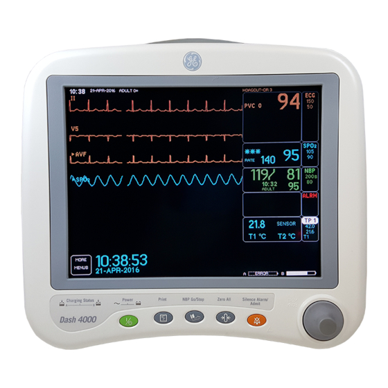
SAM™ module interface. Battery Power Charging Status Graph NBP Go/Stop Zero All Trim Knob Silence Alarm/ Admit 001C 051D 003A Dash 3000 monitor Dash 4000 monitor Dash 5000 monitor NOTE For compatibility information, contact Technical Support. Dash 3000/4000/5000 2000966-542D... - Page 23 A Trim Knob™ control provides single control operation of virtually all patient monitor functions. Patient cable connectors 002A Left side view On the left of the patient monitor, you can find the built-in writer and the battery compartment. 925B 2000966-542D Dash 3000/4000/5000...
- Page 24 The internal speaker provides sound for audible alarms. For better sound quality do not block speaker. voltage and current Identifies the voltage and electrical current requirements requirements for proper and safe operation of this monitor. Dash 3000/4000/5000 2000966-542D...
- Page 25 Optional alarm light indicator An optional alarm light indicator may be built into the handle of the Dash 3000 patient monitor or into the display bezel of the Dash 4000/ 5000 patient monitor. When activated, the LED indicator flashes red for...
-
Page 26: Controls And Indicators
The Trim Knob control is a 24-position rotary control with a push selection switch. Function or power keys Dash 3000/4000 patient monitors Power, Print, NBP Go/Stop, Zero All, Silence Alarm/Admit. Dash 5000 patient monitor Power, Standby, Admit/Discharge, NBP Go/Stop, NBP Auto, Print, Silence Alarm, Zero All, Trend, Main Display. - Page 27 Battery indicators are located on the front panel of the patient monitor. They indicate when battery power is used and the battery charging status. Battery power indicators Dash 3000 Charge status indicators 009A Battery power...
- Page 28 A battery capacity gauge for each battery present displays below the parameter blocks in the lower right corner of the display. The capacity gauge indicates the remaining charge capacity (usable energy left) for each battery. Dash 3000/4000/5000 2000966-542D...
-
Page 29: Exchangeable Or Compatible Battery Packs
EXPLOSION OR FIRE - Using non-recommended batteries could result in injury/burns to patients and users. Only use batteries recommended or manufactured by GE. The warranty can be voided if non-recommended batteries are used. Dash patient monitors running software versions 5.4 or later only recognize and charge GE recommended batteries. -
Page 30: Optional Components
When a Dash patient monitor is connected to the docking station, only the docking station’s Ethernet port is active. The Dash patient monitor’s network port remains inactive until the patient monitor is disconnected from the docking station. 2-10 Dash 3000/4000/5000 2000966-542D... - Page 31 The remote display requires: Dash Port 2 docking station, Dash 3000/4000 patient monitor software version 5 through version 7.1 with Dash Port 2 software version 2.0, or Dash 3000/4000/5000 patient monitor software version 7.2 or later ...
- Page 32 Equipment overview: Components Wireless connection The flexibility of the optional GE CARESCAPE Network is increased by using the wireless network. The wireless connection allows the user to roam from one access point to another, maintaining a strong seamless connection to the CARESCAPE Network. GE offers the 802.11a/b/g wireless option.
-
Page 33: Optional Remote Control
The optional remote control provides all patient monitor controls on a portable component with a Trim Knob control, and allows the user to operate the patient monitor from across the room. Eighteen hard keys are configured for adult, neonatal, or operating room applications. 821A 2000966-542D Dash 3000/4000/5000 2-13... -
Page 34: Software Packages And Software Options
(AMI) in women. The CARESCAPE Network option enables you to view other patients on the network, interface with a central station and other network devices, and perform Combo or Rover Combo monitoring. 2-14 Dash 3000/4000/5000 2000966-542D... -
Page 35: Ethernet Communication
It uses the star topology with a switch as the hub of the segment. A maximum of 100 meters or 328 feet is the longest length of twisted pair cable allowed. The maximum number of devices on the GE CARESCAPE Network is 1,000. -
Page 36: Network Terms
Subnet A subnet is a logical segment of a larger network that shares a common IP address range as defined by a subnet mask. Proper subnetting can improve the performance and security of a network. 2-16 Dash 3000/4000/5000 2000966-542D... -
Page 37: Theory Of Operation
DAS Module AC Mains Power Flex Power Supply Wireless Patient Board Card Connections Patient Connector DAS Board Flex Alarm Light Processor Board Writer Backlight Speaker Inverter Display Peripheral Expansion Connector Keypad Processor/Power Management Subassembly Display Subassembly 516B 2000966-542D Dash 3000/4000/5000 2-17... -
Page 38: Power Supply
All remaining DAS functions (e.g., pulse oximetry, NBP, invasive pressure, temperature, cardiac output, and CO ) share a common isolation barrier. NOTE The patient monitor supports three SPO2 configurations, Generic Ohmeda SPO2, Masimo SET SPO2, and Nellcor OxiMax SPO2. 2-18 Dash 3000/4000/5000 2000966-542D... - Page 39 Equipment overview: Theory of operation DAS block diagram with generic Ohmeda SPO2 ISOLATION BARRIER 528B 2000966-542D Dash 3000/4000/5000 2-19...
- Page 40 The patient monitor accepts the blue color-coded pulse oximetry connector (compatible with Eagle 3000 monitor, Eagle 4000 monitor, and the Tram x50-series modules). The patient monitor with Generic Ohmeda SPO2 supports Nellcor probes. 2-20 Dash 3000/4000/5000 2000966-542D...
- Page 41 The temperature connector and measurement circuits are shared with the cardiac output monitoring function; therefore you cannot use both functions concurrently. A signal in the patient cable indicates the appropriate function. 2000966-542D Dash 3000/4000/5000 2-21...
- Page 42 Patient alarms with adjustable high and low limits for inspired CO expired CO , and respiration rate are provided. An additional patient alarm for no breath detected is provided. System alarms for various sensor conditions are provided. The patient monitor accepts the yellow color-coded connector. 2-22 Dash 3000/4000/5000 2000966-542D...
- Page 43 Equipment overview: Theory of operation DAS block diagram with Masimo SET SPO2 931B 2000966-542D Dash 3000/4000/5000 2-23...
- Page 44 BP channels and Dinamap SuperSTAT NIBP Except for the SPO2 parameter and additional 2 IBPs, the DAS with the Masimo SET SPO2 parameter supports the same parameters as DAS with the GE Ohmeda SPO2 parameter. Refer to “ECG” on page 2-20.
- Page 45 Equipment overview: Theory of operation DAS block diagram with Nellcor 05 (OxiMax) SPO2 932A 2000966-542D Dash 3000/4000/5000 2-25...
- Page 46 BP channels and Dinamap SuperSTAT NIBP Except for the SPO2 parameter and additional 2 IBPs, the DAS with the Nellcor OxiMax SPO2 parameter supports the same parameters as DAS with the GE Ohmeda SPO2 parameter. Refer to “ECG” on page 2-20.
-
Page 47: Processor/Power Management Subsystem
The devices used in the core processing architecture all operate at 3.3 V to minimize power consumption, yet the main processor and ASIC are tolerant of 5 V hardware peripherals. 2000966-542D Dash 3000/4000/5000 2-27... - Page 48 Equipment overview: Theory of operation Block diagram of microprocessor and power management subsystem 574B 2-28 Dash 3000/4000/5000 2000966-542D...
- Page 49 Memory controller for synchronous flash General-Purpose Chip-Select Machine Memory and peripheral device control LCD Controller Color display Compact Flash Wireless Card Controller Wireless card Writer communication System Phase-Locked Loop (SPLL) Generation of system clock from crystal oscillator 2000966-542D Dash 3000/4000/5000 2-29...
- Page 50 1-minute resolution patient trends, an error log containing 50 input errors, and 50 output errors and storage for the CPM buffers. The patient monitor configuration data such as Internet and Ethernet addresses, unit name and bed number are maintained in memory. 2-30 Dash 3000/4000/5000 2000966-542D...
- Page 51 12-bit serial DAC. Cal data is stored on the processor/ power management PCB. Defib Sync The QRS complex of ECG data acquired from the DAS generates the marker-out signal. A software selectable pulse width and pulse amplitude is provided in the Boot Loader Menu. 2000966-542D Dash 3000/4000/5000 2-31...
- Page 52 Optional alarm light indicator An alarm light indicating two levels of visual alarms resides in the handle of the Dash 3000 patient monitor and in the display bezel of the Dash 4000/5000 patient monitors. Red and yellow alarm lights illuminate by addressing an ASIC output port. The Dash 3000 alarm light interfaces to the processor/power management PCB via the 40-pin writer interface.
- Page 53 If none of the above exist, then the patient monitor is a stand-alone monitor. Async communication Asynchronous communication ports comply with the GEMMS AutoPort protocol and are provided through an 8-pin RJ-45 port and the 20-pin peripheral interface described in the next section. 2000966-542D Dash 3000/4000/5000 2-33...
- Page 54 Each one of the four outputs are individually current limit protected against overload and short circuit. Battery subsystem Battery charging and control is accomplished on the processor/power management PCB. The battery is a smart battery and features an on-pack fuel gauge. 2-34 Dash 3000/4000/5000 2000966-542D...
-
Page 55: Lithium-Ion Battery Power
Do not place the patient monitor near a heat vent or near heat- generating equipment, such as computer monitors. Avoid placing the patient monitor in corners where the airflow may be restricted. 2000966-542D Dash 3000/4000/5000 2-35... - Page 56 Identify battery charge capacity using the patient monitor that has 100% Design Capacity and is charged to of this capacity approximately Full Charge Capacity declines, the approximate run time of a fully charged battery will decrease. 2-36 Dash 3000/4000/5000 2000966-542D...
- Page 57 If after the condition cycle has been completed, the battery does NOT meet the target performance, then the battery charger will illuminate a “fail” light. 2000966-542D Dash 3000/4000/5000 2-37...
- Page 58 If communication with the battery has failed, NO COMM displays in the SLOT STATUS row and UNKNOWN displays in all other rows. If a battery is incompatible, INCOMPAT displays in the SLOT STATUS column and UNKNOWN displays in all other fields. 2-38 Dash 3000/4000/5000 2000966-542D...
- Page 59 As a battery ages, its maximum charge level becomes a smaller percentage of its Design Capacity. The solid portion represents the current charge level of the battery as a percentage of its maximum Full Charge Capacity. 2000966-542D Dash 3000/4000/5000 2-39...
-
Page 60: Speaker
The Dash 3000 handle houses the optional alarm light. This light is visible for 360° surrounding the patient monitor. The light is intended for applications when the audible notification is not useful or effective, such as noisy environments (e.g., emergency vehicles) or quiet environments... - Page 61 A transfer function using byte-sized transfers is used to ensure the access time to the card is minimized. The packet length and pointer is returned to the ethernet stream. 2000966-542D Dash 3000/4000/5000 2-41...
-
Page 62: Storage And Backup
Monitor Setup menu. Patient monitor settings The processor/power management PCB stores default patient monitor settings in non-volatile memory. The user must restore the original settings if replacing the board. 2-42 Dash 3000/4000/5000 2000966-542D... -
Page 63: Optional Thermal Printer
0.1 to 50 mm/s. The printer software is loaded independently from the patient monitor’s software. In the patient monitor, the printer module limits its current consumption to stay within its allocated system power budget. 2000966-542D Dash 3000/4000/5000 2-43... - Page 64 Equipment overview: Theory of operation 2-44 Dash 3000/4000/5000 2000966-542D...
-
Page 65: Installation
Installation 2000966-542D Dash 3000/4000/5000... -
Page 66: Installation Overview
8. Connect patient cables per the operator’s manual. 9. Qualified personnel must perform the “Dash installation checkout procedure” on page 3-8, and should record the values of each required electrical safety test in the “Checklist” on page D-1. Dash 3000/4000/5000 2000966-542D... -
Page 67: Inspection
4. Inspect the display face for marks, scratches, or other damage. NOTE Physical damage to the flat panel display glass may pose an implosion hazard. 5. Safety labels and inscription on the device are legible. NOTE Damaged cables or equipment should be replaced by service personnel. 2000966-542D Dash 3000/4000/5000... -
Page 68: Before You Begin
Before you begin... The following installation information assumes that the equipment is new from GE manufacturing. The monitor was thoroughly tested before it was shipped. If intending to use the Dash patient monitor under battery power, consider charging the batteries in a charger during the checkout procedures. -
Page 69: Connections
The TRAM-rac 2A module housing connects to the patient monitor via a standard category 5 patch cable (PN 418335-002) that plugs into the Aux port on the patient monitor and to the Auto Port on the back of the TRAM-rac 2A module housing. 2000966-542D Dash 3000/4000/5000... - Page 70 The remote control is programmed for specific care areas (adult, neonatal, or operating room). NOTE The error message WARNING: REMOTE MISMATCHED WITH MONITORING MODE displays if a mismatched remote control is connected to the patient monitor. Dash 3000/4000/5000 2000966-542D...
-
Page 71: Power Up
All front panel indicators will illuminate until the power-up sequence is complete. After approximately 20 seconds you should see a display on the screen. Configure Go to “Configuration” on page 4-1 to configure and set up the Dash patient monitor for patient use. 2000966-542D Dash 3000/4000/5000... -
Page 72: Dash Installation Checkout Procedure
Installation: Dash installation checkout procedure Dash installation checkout procedure GE recommends that qualified personnel shall perform the following tests, and should record the results on the “Checklist” on page D-1 The Dash unit has been thoroughly tested before leaving manufacturing. -
Page 73: Configuration
Configuration 2000966-542D Dash 3000/4000/5000... -
Page 74: Before You Begin
CARESCAPE Network for the sake of sharing patient data. The patient monitor communicates with central stations, printers, and other related equipment. This network is essentially an internet implementation. NOTE The CARESCAPE Network is a purchased option. Dash 3000/4000/5000 2000966-542D... -
Page 75: Service Menus
Do not ‘experiment’ with any commands found in the service menus. Experimenting with service commands can lead to lost patient data, damaged operating system software for the patient monitor, and even affect the CARESCAPE Network. 2000966-542D Dash 3000/4000/5000... -
Page 76: Boot Loader Service Menu
A unique password is required for each option. Contact your sales/service representative to obtain a password. You must provide your product serial number and internet address. (The internet address is displayed in the Boot Code banner information.) Dash 3000/4000/5000 2000966-542D... -
Page 77: Main Menu Service Mode
1. Select MORE MENUS > MONITOR SETUP > SERVICE MODE > 2. Enter password using the Trim Knob control to select the day and month from patient monitor screen with leading zeros. (e.g. July 4 = 0407). 2000966-542D Dash 3000/4000/5000... - Page 78 Service Mode menu options Menu option Description REVIEW ERRORS For advanced troubleshooting by GE engineers. Error log data can be transferred over the network to a central station and then loaded onto a diskette for review. Refer “Error messages” on page 6-5 for details.
- Page 79 An incorrect internet address may also prevent the patient monitor from viewing other monitors on the network even though the unit names match. Whether or not this can occur depends on the network topology at the installed site. 2000966-542D Dash 3000/4000/5000...
- Page 80 (Refer to “Set time and date” on page 4-23 for detailed procedures.) WARNING Loss of patient history. This menu should rarely be used because patient histories will be lost. Dash 3000/4000/5000 2000966-542D...
-
Page 81: Procedures
“Advanced user procedures” on page 4-23 to “Set time and date” on page 4-23 “Transfer monitor defaults” on page 4-24 After completing all necessary procedures, go to “Functional and electrical safety checks” on page 8-1. 2000966-542D Dash 3000/4000/5000... -
Page 82: Set Print Locations
5. Select PRINT WINDOW LOCATION. 6. Using the Trim Knob control, choose the print window location from the list. 7. Select 12 LEAD PRINT LOCATION. 8. Using the Trim Knob control, choose the 12 lead print location from the list. 4-10 Dash 3000/4000/5000 2000966-542D... -
Page 83: Service Mode Settings
NUMBER. ↑ ↓ 041A 2. Use the Trim Knob control to select and change each character. Up to five characters may be entered. 3. Select SET BED NUMBER and press the Trim Knob control to exit. 2000966-542D Dash 3000/4000/5000 4-11... -
Page 84: Patient-Monitor Type
2. Rotate Trim Knob control to select the type of environment the patient monitor will be used in. 3. Press Trim Knob control to exit. Your selection displays at the top left of the screen after the date. 4-12 Dash 3000/4000/5000 2000966-542D... -
Page 85: Admit Menu
“Service Mode settings” on page 4-11) and select MENU SETUP > ADMIT MENU. ↑ ↓ 513A 2. Use the Trim Knob control to select the function of the patient monitor. 3. Press Trim Knob control to exit. 2000966-542D Dash 3000/4000/5000 4-13... -
Page 86: Confirm Or Configure Wireless Lan
Entering a WEP hex key clears out the pass key. The Hospital IT or a group that is responsible for the hospital's wireless network can obtain the SSID and security settings (type, pass key and key index) for the 802.11a/b/g wireless Dash. 4-14 Dash 3000/4000/5000 2000966-542D... - Page 87 9. Select RTS THRESHOLD and set to 2347, unless otherwise specified in the wireless network design. 10. Select FRAG. THRESHOLD and set to 2346, unless otherwise specified in the wireless network design. 11. Select ANTENNA and set to ENABLED. 2000966-542D Dash 3000/4000/5000 4-15...
- Page 88 WPA2-PSK (AES-CCMP) setting in the access point in order for it to communicate properly. KEY INDEX (only required for WEP 128 bit) When WEP 128 bit security is selected, the wireless Dash and the wireless network need to share the same key index. 4-16 Dash 3000/4000/5000 2000966-542D...
- Page 89 QoS Settings. Default QoS configuration is WMM. Dash also supports the upstream Quality of Service with the default values for QoS parameters (CWmin, CWmax, AIFS, TXOP and DSCP markings), which are available in BOOT MENU for configuration. 2000966-542D Dash 3000/4000/5000 4-17...
-
Page 90: Boot Code Settings
2. Select Line Frequency then choose 50 Hz or 60 Hz line frequency. 3. Select Exit and wait for the patient monitor to display the message, “Writing settings to Flash config mem...” 4. Manually reboot the patient monitor to implement this change. 4-18 Dash 3000/4000/5000 2000966-542D... -
Page 91: Set Cic And Qs Protocol
5. Refer to “Service Mode settings” on page 4-11 and select MONITOR SETTINGS > SET LOCATION, then select SET SITE NUMBER. Transcutaneous Pace Blank Length This menu option is reserved for future use and should not be changed. 2000966-542D Dash 3000/4000/5000 4-19... -
Page 92: Set Country Selection
Configuration: Boot Code settings Set Country Selection Select DEFAULT or FRANCE to choose a particular set of GE factory defaults. 1. Activate Boot Code (“Boot Code settings” on page 4-18) and select SET CONFIGURATION menu option. 2. Select Country Selection and choose language. -
Page 93: Enable Or Disable Afib Identification
To verify the option has been enabled on the patient monitor, 1. Select the following menu options: MORE MENUS > MONITOR SETUP > SOFTWARE CONFIGURATION. 2. Verify that ECG INTELLIRATE is listed under “ENABLED SOFTWARE OPTIONS.” To change the status of this feature, 2000966-542D Dash 3000/4000/5000 4-21... -
Page 94: Analog Out Buzz
“Writing settings to Flash config mem...” 5. Manually reboot the patient monitor to implement this change. Completion The patient monitor is now ready for normal operation. At this time, perform procedures in “Functional and electrical safety checks” page 8-1. 4-22 Dash 3000/4000/5000 2000966-542D... -
Page 95: Advanced User Procedures
3. Select SET TIME and use the Trim Knob control to change the time. The time displays as a 24-hour military clock. 4. Select SET DATE and use the Trim Knob control to change the date. 2000966-542D Dash 3000/4000/5000 4-23... -
Page 96: Transfer Monitor Defaults
(e.g., Default or France). The following defaults transfer when using this feature: all patient monitor defaults wireless LAN configuration custom default names 12 SL location 12 SL site 4-24 Dash 3000/4000/5000 2000966-542D... - Page 97 3. Enter password using the Trim Knob control to select the day and month from patient monitor screen with leading zeros. (e.g. July 4 = 0407) 4. Select MONITOR SETTINGS. 5. Select STORE DEFAULTS FOR NETWORK TRANSFER. 6. Select YES to the confirmation popup menu. 2000966-542D Dash 3000/4000/5000 4-25...
- Page 98 After copying patient monitor defaults from another bed (the server patient monitor), verify that the defaults were transferred and arrhythmia levels are as desired. See “Monitor defaults transfer” page 6-11 for troubleshooting any errors during this process. 4-26 Dash 3000/4000/5000 2000966-542D...
-
Page 99: Preventive Maintenance
Preventive maintenance 2000966-542D Dash 3000/4000/5000... -
Page 100: Maintenance Schedule
“Functional and electrical safety checks” on page 8-1—Perform electrical safety tests, checkout procedures and calibration every 12 months after installation. GE recommends that the qualified personnel performing the tests should record the values of the tests in the “Checklist”... -
Page 101: Visual Inspection
APIC Guidelines for Selection and Use of Disinfectants (1996): Sodium hypochlorite (5.2% household bleach) minimum 1:500 dilution (minimum 100 ppm free chlorine) and a maximum 1:10 dilution. 2000966-542D Dash 3000/4000/5000... -
Page 102: Cautions
Abrasive cleaners or solvents of any kind. Acetone Ketone Betadine Alcohol-based cleaning agents Sodium salts Never autoclave or steam clean the device. Always use household glass cleaner to clean the touchscreen or standard displays. Dash 3000/4000/5000 2000966-542D... -
Page 103: Impact Or Results Of Improper Cleaning Products And Processes
Products that contain active ingredients and solutions similar to these products should be avoided. Storage Always remove batteries when the device is not in use (even for short periods of time). Store in a dry well-ventilated area. 2000966-542D Dash 3000/4000/5000... -
Page 104: Clean The Print Head
5. Wipe the print head with alcohol and a nonabrasive material/cotton swab in an side to side motion. Continue wiping until the cloth/swab wipes clean. 6. Wipe paper drive roller clean of any bits of paper and debris with alcohol and a nonabrasive material. Dash 3000/4000/5000 2000966-542D... -
Page 105: Cleaning, Disinfecting And Storing Ge Ecg Cables And Leadwires
Preventive maintenance: Cleaning, disinfecting and storing GE ECG cables and leadwires Cleaning, disinfecting and storing GE ECG cables and leadwires Cleaning and disinfecting 1. Remove cables and leadwires from the handheld device or system before cleaning. 2. Use care in cleaning leadwires to prevent pulling the long wires from the connector ends. -
Page 106: Sterilization
Preventive maintenance: Cleaning, disinfecting and storing GE ECG cables and leadwires Sterilization NOTE EtO sterilization is not recommended, but may be required for cables and leadwires. Frequent sterilization will reduce the useful life of cables and leadwires. Sterilize with ethylene oxide gas (EtO) at a maximum temperature of 50°... -
Page 107: Cleaning Products To Avoid
Products that contain active ingredients and solutions similar to these products should also be avoided. Cleaning other applied parts For other applied parts such as temperature sensors, catheters, pulse oximetry probes, and NBP cuffs, you must consult the manufacturer for cleaning, sterilization, or disinfecting method 2000966-542D Dash 3000/4000/5000... -
Page 108: Battery Maintenance
Inside a patient monitor that is connected to an AC power source. NOTE To extend the life of the battery, GE recommends that you charge the battery using the external Cadex SMart Two+ charger. NOTE The Cadex SMart Two+ charger is no longer available for purchase. -
Page 109: How To Condition The Battery
Inside a patient monitor that is connected to an AC power source. NOTE To extend the life of the battery, GE recommends that you condition the battery using the external Cadex SMart Two+ charger. NOTE The Cadex SMart Two+ charger is no longer available for purchase. -
Page 110: How To Store The Battery
AC power source and is not powered by battery on a regular basis, the life of the battery may be less than 12 months. GE recommends that you remove the battery and store it near the patient monitor until it is needed for transport. - Page 111 3. Select Wake Up Battery from the Service Menu. 4. Insert the “sleeping” battery into slot A of the patient monitor. NOTE In some languages, slot A is identified as slot 1 and slot B is identified as slot 2. 2000966-542D Dash 3000/4000/5000 5-13...
-
Page 112: How To Replace The Batteries
EXPLOSION OR FIRE — Using non-recommended batteries could result in injury/burns to the patient or users. Only use batteries recommended or manufactured by GE. The warranty can be voided if non-recommended batteries are used. 1. Open the battery doors on the left side of the patient monitor, along the bottom. -
Page 113: Rechargeable Battery Recycling
In the United States and Canada, the Rechargeable Battery Recycling Corporation (RBRC) can help you locate your nearest rechargeable battery collection site. You can contact RBRC by telephone or by accessing their internet web site. telephone: 1-800-8-BATTERY (800-822-88379) internet address: www.rbrc.org 2000966-542D Dash 3000/4000/5000 5-15... -
Page 114: About The Cadex Smart Two+ Charger
Charger fault. FAIL and CONDITION Conditioning is complete — fail target. Equipment software requirements The patient monitor must use Dash 3000/4000 software version 2A or later. The Cadex SMart Two+ charger must use software version 1.31 or later. -
Page 115: Clear The Stored Patient Data Memory
Preventive maintenance: Clear the stored patient data memory Clear the stored patient data memory Admit and discharge a test patient every 12 months to clear the patient monitor’s stored patient data memory. 2000966-542D Dash 3000/4000/5000 5-17... - Page 116 Preventive maintenance: Clear the stored patient data memory 5-18 Dash 3000/4000/5000 2000966-542D...
-
Page 117: Troubleshooting
Troubleshooting 2000966-542D Dash 3000/4000/5000... -
Page 118: Fault Analysis
GE recommends formal service training before repairs are attempted. These troubleshooting procedures combined with training provide the service technician with skills necessary to service and repair a patient monitor in the event of a malfunction. - Page 119 No display Display may be in standby mode. Press the POWER button. If display still does not appear within 20 seconds, replace the display Backlight inverted may be defective. assembly. Replace back light inverter. 2000966-542D Dash 3000/4000/5000...
-
Page 120: Acquisition Pcb Symptoms
PCB failure. All of these are functions controlled by microcontroller or graphics processing circuitry located on the Processor/Power Management PCB. Dash 3000/4000/5000 2000966-542D... -
Page 121: Error Messages
“Maintenance schedule” on page 5-2. WLAN PRIORITY SETTING IS NOT SUPPORTED FOR THIS CARD For the 802.11 a/b/g wireless option, the PRIORITY configuration setting is not used. This message displays if you attempt to change this configuration setting. 2000966-542D Dash 3000/4000/5000... - Page 122 Complete all of the recommended checkout, electrical safety tests, calibration tests listed in “Functional and electrical safety checks” on page 8-1. The processor pcb may be defective. Refer to “Replace CPU/battery housing assembly” on page 7-44 to replace the processor pcb. Dash 3000/4000/5000 2000966-542D...
-
Page 123: Battery Alarms And Messages
A serious failure has occurred while using or charging the battery. An incompatible battery may be installed. CHECK BATT STATUS System MESSAGE Charger Failure Charger communications have failed. NOTE INTERNAL CHARGER FAILED, CALL SERVICE also appears in the Battery Status information window. 2000966-542D Dash 3000/4000/5000... -
Page 124: Battery Messages Displayed In The Battery Status Information Window
If the battery is asleep and you need to “wake up” the battery, see “How to wake up the battery” on page 5-12. If the battery will not “wake up” it is probably faulty and should be replaced. Check the battery status screen in the Service Menu. Dash 3000/4000/5000 2000966-542D... -
Page 125: Writer Or Printer
Check all cables for a good connection. Check configured alarms and manual print locations at the patient monitor. Internal If the writer does not print, check that it has paper and that the paper is loaded properly. 2000966-542D Dash 3000/4000/5000... -
Page 126: No Waveform At Central Station
Ensure the internet protocol (IP) addresses are configured correctly. For a troubleshooting tree with more information, refer to “Problem: No waveforms or parameters are displayed at the CIC Pro center” page B-5. 6-10 Dash 3000/4000/5000 2000966-542D... -
Page 127: Monitor Defaults Transfer
SOFTWARE FEATURE LEVEL set to different software levels (e.g., Basic, MISMATCH Cardiac, Cardiopulmonary). ERROR COPYING UNIT DEFAULTS - The server and client patient monitors are COUNTRY CODE MISMATCH set to different country codes (e.g., DEFAULT or FRANCE). 2000966-542D Dash 3000/4000/5000 6-11... -
Page 128: Change Internet Address
3. Keep holding NBP Go/Stop (or NBP Auto) and ZERO ALL (FUNCTION) until the Boot Loader information appears on the display. 4. Select Service Menu > Option Menu > Change Internet Address to acquire information required for password. 6-12 Dash 3000/4000/5000 2000966-542D... -
Page 129: Review Errors
If the CARESCAPE Network software option is enabled, the error logs may also be transferred over the network to a central station and copied onto diskette for further review or sent to GE personnel for review. The transferring procedure is in “Get error logs”... -
Page 130: Useful Error Data
This should only be done by qualified service personnel. Video test was completed. This test should only be performed by qualified service personnel. Time was changed from this patient monitor. This helps determine how the system-wide time may have been altered. 6-14 Dash 3000/4000/5000 2000966-542D... - Page 131 Forced Restart—the system was restarted by a known condition (internet address change, video test, etc). Date and time The date and time the event or problem occurred. Error number A sequential number that is used to identify each event/problem. 2000966-542D Dash 3000/4000/5000 6-15...
-
Page 132: Get Error Logs
Get error logs Get logs via PC using netUpdate These instructions describe how to copy log files from a Dash 3000/4000/ 5000 patient monitor to a PC using one of the following configurations: PC or PC laptop connected to a Dash 3000/4000/5000 patient monitor ... - Page 133 MC network Ethernet tap, verify that the patient monitor or docking station is also connected to the MC network Ethernet tap. 3. Power on the PC. 4. Continue with the instructions, “Change the PC’s IP address” on page 6-18. 2000966-542D Dash 3000/4000/5000 6-17...
- Page 134 Start > Settings > Control Panel. Double-click System and select the Computer Name tab. Record the full computer name: __________________________________________ Close all open windows. Restart the PC. Continue with the instructions, “Disable firewall or networking services” on page 6-19. 6-18 Dash 3000/4000/5000 2000966-542D...
- Page 135 1. Make sure the patient monitor is in monitoring mode. 2. Insert the CD-ROM into the CD-ROM drive. 3. Double-click My Computer. 4. Create a folder for the log files in the root directory. (e.g. C:\logs) 2000966-542D Dash 3000/4000/5000 6-19...
- Page 136 9. Select the folder you created for log files, then click OK. 10. The log file displays and a message at the top of the netUpdate window displays a message that the log retrieval was successful. 6-20 Dash 3000/4000/5000 2000966-542D...
-
Page 137: Get Logs Via Cic
CARESCAPE Network. Access the COPY LOGS menu 1. Beginning with the Centralscope central station Main Menu, select CENTRAL SETUP > SERVICE. 2. Enter password: MEI CS 123 3. Select COPY LOGS. The Copy Logs menu displays. 2000966-542D Dash 3000/4000/5000 6-21... - Page 138 2. Using the Trim Knob control, change the error log date. Note that one of the selections is ALL, which retrieves all stored error logs from the specified device. When the desired date displays, press the Trim Knob control. 046A 6-22 Dash 3000/4000/5000 2000966-542D...
- Page 139 Trim Knob control to start. 047A Once the copy function begins the Start Copy button changes to show the function: “copying.” Eject floppy Select this option to eject the floppy diskette from the central station’s disk drive. 2000966-542D Dash 3000/4000/5000 6-23...
-
Page 140: Wireless Lan
REVISION AND ID Menu, one in the Service Menu., and one in the lower right corner of the display. REVISION AND ID Menu 944A, 945A, 946A Service Menu (page 1) Service Menu (page 2) 6-24 Dash 3000/4000/5000 2000966-542D... -
Page 141: Access Service Mode
(hardware and software) installed or the wireless feature is not enabled. Go to “Confirm or configure wireless LAN” on page 4-14 to enable the feature, then go “802.11a/b/g” on page 6-26 for further troubleshooting. 802.11a/b/g Wireless technology 944A 2000966-542D Dash 3000/4000/5000 6-25... -
Page 142: 802.11A/B/G
For proper operation of the 802.11a/b/g wireless patient monitor, analyze the association, firmware version, signal strength and transmit rate status. 0X 5.0.2.0-005R XX XX Firmware version Association status Signal strength status Transmit rate status 6-26 Dash 3000/4000/5000 2000966-542D... - Page 143 1 Mbps 2 Mbps 5.5 Mbps 6 Mbps 9 Mbps 11 Mbps 12 Mbps 18 Mbps 24 Mbps 36 Mbps 48 Mbps 54 Mbps 1. Signal strength status is not a calibrated SNR (signal/noise ratio) value. 2000966-542D Dash 3000/4000/5000 6-27...
- Page 144 IT department for further troubleshooting. If association status, signal strength and transmit statuses meet the requirements, then the wireless patient monitor is not the source of the problem. Contact your local hospital IT department for further troubleshooting. 6-28 Dash 3000/4000/5000 2000966-542D...
- Page 145 3. If the ASSOCIATION status in the WIRELESS LAN STATUS window is other than CONNECTED, see “Confirm or configure wireless LAN” on page 4-14 to check if the wireless feature is enabled. Contact GE Technical Support for additional assistance. 2000966-542D Dash 3000/4000/5000 6-29...
- Page 146 Troubleshooting: Wireless LAN 6-30 Dash 3000/4000/5000 2000966-542D...
-
Page 147: Field Replaceable Units
Field replaceable units 2000966-542D Dash 3000/4000/5000... -
Page 148: Ordering Field Replaceable Units
If you require additional information or troubleshooting assistance, contact GE Technical Support. To order parts, contact Service Parts at the address or telephone number listed on the “How to Reach Us...” page found in the front of this manual. -
Page 149: Field Replaceable Units
Includes display components, flex assembly, labels and hardware for Dash 4000 patient monitor. (no LCD) 2026653-006 DASH 3K DISPLAY ASSEMBLY Includes complete display assembly (including flex and inverter) and labels for Dash 3000 patient monitor. 2000966-542D Dash 3000/4000/5000... - Page 150 12” Dash 5000 patient monitor. Inverter assemblies - See “Replace display assembly parts” on page 7-26 for disassembly. 2026653-022 DASH 3K DISPLAY INVERTER Includes display inverter and cable for Dash 3000 patient monitor. 2026653-023 DASH 4K DISPLAY INVERTER Includes inverter.
- Page 151 7-34 for disassembly. 2026653-015 DASH WRITER FLEX Includes writer flex and hardware. 2026653-021 WRITER 50MM CS2 Includes light gray writer with captive hardware. Speaker assembly - See “Replace main unit parts” on page 7-34 for disassembly. 2000966-542D Dash 3000/4000/5000...
- Page 152 Labels 2026653-027 DASH 3K/4K/5K SIDE LABELS Includes all languages 2026653-028 DASH 5K FRONT LABELS Includes all languages 2026653-029 DASH 4K FRONT/DAS LABELS Includes all languages 2026653-030 DASH 3K FRONT/DAS LABELS Includes all languages Dash 3000/4000/5000 2000966-542D...
-
Page 153: Disassembly Guidelines
NOTE GE recommends that you assemble the patient monitor using the new fasteners (screws, washers, etc.) provided in the FRU Kits. Some fasteners, like the screws with a thread locking coating, are not intended to be re-used more than three times. -
Page 154: Hardware Precautions
Handle all PCB assemblies by their edges. Do not flex or twist the circuit board. These guidelines may not guaranty a 100% static-free workstation, but can greatly reduce the potential for failure of any electrical/electronic assemblies being serviced. Dash 3000/4000/5000 2000966-542D... -
Page 155: Replacement Procedures
To prevent cracking the plastic components, do not overtighten the screws fastening the plastic components together. To prevent cross-threading plastic components, carefully start threading the screws by hand, then finish tightening the screws using an appropriate hand tool. 2000966-542D Dash 3000/4000/5000... -
Page 156: Remove Or Replace Handle Assembly
7-18. NOTE For Dash 3000 only: If the replacement handle assembly has an alarm light, the DAS assembly must be removed to connect the cable to J1 on the writer board. Refer to “Replace DAS assembly”... - Page 157 To completely remove the handle from the main unit, do the following: Apply pressure against the antenna cables (to prevent pulling on the cables) and carefully remove the antenna label from the Dash monitor. Discard the used label. 966B 2000966-542D Dash 3000/4000/5000 7-11...
- Page 158 CF card eject button. To press the CF card eject button, carefully insert the flat end of a pen approximately 1- inch deep and push the CF flash card eject button as shown. CF card eject button 973A 974A 7-12 Dash 3000/4000/5000 2000966-542D...
- Page 159 Provide enough slack in the cables to allow the handle to be removed if future repairs are required. Remove the protective backing from the short antenna label and position the label over the untwisted antenna cables as shown. 2000966-542D Dash 3000/4000/5000 7-13...
- Page 160 Be sure that the cables are lying flat and are not twisted around each other. 955B Remove the protective backing from the right side of the antenna label and secure the antenna cables in place. 7-14 Dash 3000/4000/5000 2000966-542D...
- Page 161 Remove the protective backing from the left side of the antenna label and secure the antenna cables as shown. 958B k. Continue to wrap the antenna cables toward the righthand side of the antenna label and secure as shown. 963B, 964B, 965B 2000966-542D Dash 3000/4000/5000 7-15...
- Page 162 959C m. Insert the wireless card (with the antenna connectors facing down and the connected antenna cables on the righthand side) into the PC card bracket. Insert wireless card with antenna connectors facing down 975B, 960C 7-16 Dash 3000/4000/5000 2000966-542D...
- Page 163 Due to the larger display size of the Dash 5000 monitor, the unsecured portion of the antenna cables between the antenna label and the wireless card has very little slack. 966B p. Reinstall the display assembly. 2000966-542D Dash 3000/4000/5000 7-17...
-
Page 164: Remove Or Replace Display Assembly
580A Note: Use a screwdriver with a long blade or remove the GCX plate first for easy access to the bottom screws..and the two shorter screws from the bottom of the unit. 578B 7-18 Dash 3000/4000/5000 2000966-542D... - Page 165 If you do not handle the flex cable gently, you will damage the cable. Flex cable folds up from the bottom of the display assembly. Metal display shield plate 869A 2000966-542D Dash 3000/4000/5000 7-19...
- Page 166 Metallic display shield 870A 5. To prevent damaging the display flex cable, position the display assembly for the patient monitor you are servicing. Dash 3000 display assembly with circuit board display shield 1-inch (2.54 cm) 830A 7-20 Dash 3000/4000/5000...
- Page 167 Display assembly with metallic display shield 871A 6. Remove the two screws attaching the flex circuit to the main unit’s CPU/battery housing assembly. Remove the flex connector by pulling on the flex connector strain relief. 2 screws 543A 2000966-542D Dash 3000/4000/5000 7-21...
- Page 168 12. Refer to the figure below to determine if you need to enable or disable the alarm light on your Dash display assembly. clear lens (enable light) opaque lens (disable light) 877A J2 alarm light jumper 878A 7-22 Dash 3000/4000/5000 2000966-542D...
- Page 169 13. Connect the display assembly to the main unit. Refer to page 7-18 and re-assemble the patient monitor in reverse order. 14. Apply the Dash front panel label as shown below. Front panel label 894A 15. Complete the procedures in “Recommended checkout” on page 7-52. 2000966-542D Dash 3000/4000/5000 7-23...
-
Page 170: Replace Display Flex Assembly
Field replaceable units: Replace display flex assembly Replace display flex assembly Dash 3000 display flex assembly The Dash 3000 display assembly includes the flex assembly. 1. Remove the handle and display assemblies according to steps starting on page 7-10. 2. Replace the display assembly and reassemble the patient monitor in reverse order of disassembly. - Page 171 9. Carefully align and insert the DAS cable pins into the DAS assembly until the snap latch clicks into place. 876A 10. Reassemble the patient monitor in reverse order of disassembly. 11. Complete the procedures in “Recommended checkout” on page 7-52. 2000966-542D Dash 3000/4000/5000 7-25...
-
Page 172: Replace Display Assembly Parts
“Replace Dash 4000/5000 alarm light” on page 7-28. “Replace display inverter” on page 7-28. “Replace keypad assembly or Trim Knob control” on page 7-30. “Replace display components without LCD” on page 7-31. 7-26 Dash 3000/4000/5000 2000966-542D... -
Page 173: Open Display Assembly
Field replaceable units: Replace display assembly parts Open display assembly Follow the steps below for the patient monitor you are servicing. Dash 3000 patient monitor Dash 4000 patient monitor Dash 5000 patient monitor with display shield flex circuit Separate the patient monitor bezel from 1. -
Page 174: Replace Dash 4000/5000 Alarm Light
12 on page 7-22. 9. Re-assemble the patient monitor in reverse order. 10. Complete the procedures in “Recommended checkout” on page 7-52. Replace display inverter Follow the steps below for the patient monitor you are servicing. 7-28 Dash 3000/4000/5000 2000966-542D... - Page 175 Field replaceable units: Replace display assembly parts Dash 3000 patient monitor Dash 4000 patient monitor Dash 5000 patient monitor with display shield flex circuit 1. Flip over the display shield flex 1. Open the display assembly. Refer to page 7-27.
-
Page 176: Replace Keypad Assembly Or Trim Knob Control
Field replaceable units: Replace display assembly parts Replace keypad assembly or Trim Knob control Follow the steps below for the patient monitor you are servicing. Dash 3000 patient monitor Dash 4000 patient monitor Dash 5000 patient monitor with display shield flex circuit 1. -
Page 177: Replace Display Components Without Lcd
Field replaceable units: Replace display assembly parts Dash 3000 patient monitor Dash 4000 patient monitor Dash 5000 patient monitor with display shield flex circuit 7. Secure the new keypad with the screws. 7. Reattach the keypad cable. 6. Secure the new keypad with the screws. - Page 178 1. Open the display assembly. Refer to page 7-27. 2. Remove the LCD display. Follow the steps for the patient monitor you are servicing. Dash 3000 patient monitor Dash 4000 patient monitor Dash 5000 patient monitor with display shield flex circuit Peel back and remove the rubber Disconnect the five cable connectors.
- Page 179 4. If required, replace the display filter, front bezel, and insert. 5. Install the existing LCD display and reassemble the display assembly in reverse order. 6. Complete the procedures in “Recommended checkout” on page 7-52. 2000966-542D Dash 3000/4000/5000 7-33...
-
Page 180: Replace Main Unit Parts
961B 4. Remove the wireless card from the card slot by pressing the CF card eject button. To press the CF card eject button, carefully insert the 7-34 Dash 3000/4000/5000 2000966-542D... - Page 181 1- inch deep and push the CF flash card eject button as shown. CF card eject button 973A 974A 5. Carefully disconnect the antennas using a pen tip, small screwdriver, or needle nose pliers. 942A 2000966-542D Dash 3000/4000/5000 7-35...
- Page 182 Grey antenna cable (right) Antenna connectors 959C 7. Reinsert the wireless card into the PC card bracket. Insert wireless card with antenna connectors facing down 975B 8. Re-secure the antenna cables underneath the antenna label as shown. 962B 7-36 Dash 3000/4000/5000 2000966-542D...
-
Page 183: Replace Das Assembly
Masimo SET SPO2 and 4 BP SuperStat DAS upgrade. If the installation of software version 5 or later is required, GE recommends that you FIRST install the software. Then, install the Masimo SET SPO2 and 4 BP SuperStat hardware upgrade. - Page 184 7. If you installed the Generic Ohmeda DAS assembly, place the labels as shown below. BP 1 and BP 2 12SL (if software option was enabled) CO2, NBP, and ECG 861A NOTE The BP 1 and BP 2 label looks similar to the example below. 862A 7-38 Dash 3000/4000/5000 2000966-542D...
- Page 185 CO2, NBP, and ECG 827B NOTE The BP 1/3 and BP 2/4 label looks similar to the example below. 860A patent disclosure label 004B 9. Complete the procedures in “Recommended checkout” on page 7-52. 2000966-542D Dash 3000/4000/5000 7-39...
-
Page 186: Replace Nbp Pump Assembly
Remove four screws. 570A Disconnect this end of the tube. 4. Using a small, flat-blade screwdriver, remove the connector from the NBP assembly to the DAS assembly. 527A DAS assembly FRU NBP pump assembly FRU 526A 7-40 Dash 3000/4000/5000 2000966-542D... -
Page 187: Replace Writer Assembly Or Writer Flex
When securing the thumb screw for reassembly, first finger- tighten the thumb screw. Then, use a flat-head screw driver to tighten the screw an additional 1/4 turn. speaker harness and alarm light cable three writer flex screws thumb screw 562B 2000966-542D Dash 3000/4000/5000 7-41... -
Page 188: Replace Speaker Assembly
2. Remove the writer assembly/writer flex according to steps on page 7-41. 3. Remove the writer bracket from the frame by squeezing the sides together. 532A 4. Disconnect the speaker cable connector from the processor board. 586B 7-42 Dash 3000/4000/5000 2000966-542D... - Page 189 When securing the thumb screw on the writer flex, first finger- tighten the thumb screw. Then, use a flat-head screw driver to tighten the screw an additional 1/4 turn. 10. Complete the procedures in “Recommended checkout” on page 7-52. 2000966-542D Dash 3000/4000/5000 7-43...
-
Page 190: Replace Cpu/Battery Housing Assembly
Field replaceable units: Replace main unit parts Replace CPU/battery housing assembly 1. For Dash 3000 patient monitors, remove the handle assembly. Refer to page 7-10. For Dash 4000 or 5000 patient monitors, go to the next step. 2. Remove the display assembly from the main unit. Refer to page 7-18. - Page 191 Carefully disconnect the antennas using a pen tip, small screwdriver, or needle nose pliers. 942A d. Place the wireless card in a safe place. 4. Remove the DAS assembly according to steps starting on page 7-37. 2000966-542D Dash 3000/4000/5000 7-45...
- Page 192 7. If replacing the battery door only, install the new door and reassemble the patient monitor. Otherwise, continue with the next step. 8. Remove the four panhead screws anchoring the CPU/battery housing assembly to the frame. These screws are attached at the bottom of the unit. 517A 7-46 Dash 3000/4000/5000 2000966-542D...
- Page 193 12. If present, install the wireless card into the new CPU/battery housing assembly. CAUTION Do not pull on the 802.11a/b/g antennas or use force when connecting to the wireless card. Handle the antennas and connectors carefully as they can easily be damaged. 2000966-542D Dash 3000/4000/5000 7-47...
-
Page 194: Replace Power Supply Assembly
Replace power supply assembly 1. Remove the CPU/battery housing assembly according to steps starting on page 7-44. 2. While holding the power supply assembly with one hand, remove the four screws from the back of the unit. 575A 7-48 Dash 3000/4000/5000 2000966-542D... - Page 195 Then, use a flat-head screw driver to tighten the screw an additional 1/4 turn. 5. Reassemble the patient monitor in reverse order. 6. Complete the procedures in “Recommended checkout” on page 7-52. 2000966-542D Dash 3000/4000/5000 7-49...
-
Page 196: Replace Battery Door
1. Remove four screws holding the foot to the patient monitor. 926A NOTE Your unit may or may not have a mounting plate. The same four screws anchor the mounting plate and foot. 2. Replace the foot and screw to the patient monitor. 7-50 Dash 3000/4000/5000 2000966-542D... -
Page 197: Replace Writer Cover
Field replaceable units: Replace writer cover Replace writer cover Dash patient monitors without a writer have a blank door where the writer assembly would be installed. The door snaps into the writer space above the battery door. 927A 2000966-542D Dash 3000/4000/5000 7-51... -
Page 198: Recommended Checkout
“Wireless LAN test (option)” on page 8-52. Use this procedure if the wireless option is installed. Keypad assembly/ None “Patient monitor power-up tests” on page 8-21. Trim Knob “Display test” on page 8-45. 7-52 Dash 3000/4000/5000 2000966-542D... - Page 199 “Invasive blood pressure tests (option)” on page 8-27. “Pulse oximetry tests for GE Ohmeda SPO2 oximeter” on page 8-30. Use this procedure if you installed a GE Ohmeda DAS assembly. “Pulse oximetry tests for Masimo SET SPO2”...
- Page 200 “Wireless antenna signal strength test (option)” on page 8-49. Use this procedure if the wireless option is installed. “Wireless LAN test (option)” on page 8-52. Use this procedure if the wireless option is installed. 7-54 Dash 3000/4000/5000 2000966-542D...
-
Page 201: Functional And Electrical Safety Checks
Functional and electrical safety checks 2000966-542D Dash 3000/4000/5000... -
Page 202: Overview
7-52 for more information. Test equipment The safety tests and checkout procedures are written for the GE recommended test equipment listed for each test. If you use test equipment other than those GE recommends, you may need to slightly modify some test steps. -
Page 203: Functional Checkout Procedures
“Cardiac output tests (option)” on page 8-27 “Invasive blood pressure tests (option)” on page 8-27 “Pulse oximetry tests for GE Ohmeda SPO2 oximeter” on page 8-30 “Pulse oximetry tests for Masimo SET SPO2” on page 8-32 “Pulse oximetry tests for Nellcor OxiMax SPO2”... -
Page 204: Electrical Safety Tests
(Corrective Maintenance). Refer to “Recommended checkout” on page 7-52 for more information. GE recommends that the qualified personnel performing the tests should record the values of each required electrical safety test in the “Checklist” on page D-1. -
Page 205: Power Outlet Test
Verify line, neutral, and earth conductors are properly connected to the power cord plug and are not short-circuited. Replace the power cord, as necessary with a regulatory-approved cord for the country of use. WARNING Use only AC power cords recommended or manufactured by GE. 2000966-542D Dash 3000/4000/5000... -
Page 206: Ground (Earth) Integrity
The measuring device (MD) in the diagram below may be a DMM or part of a safety analyzer. NOTE *The measuring device (MD) represents the network and voltage measuring instrument and its frequency characteristics per IEC 60601-1. Dash 3000/4000/5000 2000966-542D... -
Page 207: Ground (Earth) Wire Leakage Current Tests
For equipment with a power supply cord, the impedance between the protective earth pin in the mains plug and any accessible metal part which is protectively earthed shall not exceed 0.2 ohms. 3. GE recommends that the qualified personnel performing the tests should record the values in the “Checklist”... - Page 208 7. Read and record the current leakage indicated on the tester. 8. Change leakage tester switches to: Polarity – REVERSE Neutral – CLOSED 9. Read and record the current leakage indicated on the tester. Dash 3000/4000/5000 2000966-542D...
-
Page 209: Enclosure (Touch) Leakage Current Test
Functional and electrical safety checks: Electrical safety tests If measured reading is greater than the appropriate specification below, the device under test fails. Contact GE Technical Support. Acceptance criteria NC (Normal condition) (USA only) 300 µA, and the device under test is powered from ... - Page 210 GND (Earth) – CLOSED 11. Read and record the current leakage indicated on the tester. 12. Change leakage tester switches to: Polarity – REVERSED Neutral – CLOSED GND (Earth) – CLOSED 8-10 Dash 3000/4000/5000 2000966-542D...
- Page 211 14. Set the power switch of the device under test to OFF. If measured reading is greater than the appropriate specification below, the device under test fails. Contact GE Technical Support. Acceptance criteria NC 100 microamperes (0.1 volts on the tester), and the device under ...
-
Page 212: Patient (Source) Leakage Current Test
5. Change leakage tester switches to: Polarity – NORMAL Neutral – OPEN GND (Earth) – CLOSED 6. Read and record the current leakage indicated on the tester. 7. Change leakage tester switches to: Polarity – NORMAL 8-12 Dash 3000/4000/5000 2000966-542D... - Page 213 Acceptance criteria NC With Ground and Neutral CLOSED – If reading is greater than 10 µA, the device under test fails. Contact GE Technical Support Acceptance criteria SFC – ground (earth), line or neutral open If any reading is greater than 50 µA, the device under test fails. Contact GE Technical Support.
-
Page 214: Patient (Sink) Leakage Current Test (Mains Voltage On The Applied Part)
1. Configure leakage tester as follows: Polarity – NORMAL Neutral – CLOSED GND (Earth) – CLOSED WARNING Shock hazard. The following step causes high voltage at the test body. Do not touch the test body. 8-14 Dash 3000/4000/5000 2000966-542D... - Page 215 Body. Connect the SPO2 Test Body to the blue SPO2 connector of the device under test. Acceptance criteria If measured reading is greater than the appropriate specification below, the device under test fails. Contact GE Technical Support. 50 µA at 120-240 VAC using the ECG cable. 2000966-542D...
-
Page 216: Bisx (Option) Current Leakage Tests
Sensor Plus simulator connections (test body) to the leakage tester. Sensor Plus simulator circular connections 2. Configure the leakage tester as follows: Polarity – NORMAL Neutral – CLOSED GND (Earth) – CLOSED 8-16 Dash 3000/4000/5000 2000966-542D... - Page 217 17. Leave the test configuration set up for the sink leakage test. Acceptance criteria NC If any reading with the ground and neutral closed is greater than 100 uA, the BISx fails this test. Contact GE Technical Support. 2000966-542D Dash 3000/4000/5000...
-
Page 218: Bisx Patient (Sink) Leakage Current Test
Acceptance criteria SFC – ground (earth), line or neutral open If any reading with the ground open is greater than 500 uA, the BISx fails this test. Contact GE Technical Support. BISx patient (sink) leakage current test This test checks the patient cable leakage current from a 115 or 220VAC source into the BISx. -
Page 219: Test Completion
6. Set the power switch on the leakage tester to OFF. Acceptance criteria If either reading is greater than 5000 µA, the BISx fails this test. Contact GE Technical Support. Test completion 1. Disconnect the leakage tester from the power outlet. -
Page 220: Functional Checkout Procedures
The following is a list of all available patient parameter and software options. 0BP (invasive) 1BP or 2BP (invasive) 3BP or 4BP (invasive) 12SL ACI-TIPI HI-RES TRENDS ETCO ) (End-tidal CO NETWORK AVOA Plus CARDIO-PULMONARY CARDIAC 8-20 Dash 3000/4000/5000 2000966-542D... -
Page 221: Patient Monitor Power-Up Tests
(batteries must have more than 10% charge). Pull that battery out and verify the other LED lights, thus indicating the unit is powered by the other battery. Reinstall battery and plug in patient monitor (or the docking station). 2000966-542D Dash 3000/4000/5000 8-21... -
Page 222: Ecg Tests
3. Observe the following while you view ECG leads I, II, III, aVL, aVF, and aVR: a “P” appears above the PVC count indicating pacemaker pulse detection is enabled, and the heart rate still reads 80 ±1 bpm. 8-22 Dash 3000/4000/5000 2000966-542D... - Page 223 Lead II:1 mV Lead III:0.5 mV Lead V:-0.5 mV 8. This completes the 5 Leadwire ECG test. Leave the ECG patient cable connected to ECG/RESP and continue to the next steps of these checkout procedures. 2000966-542D Dash 3000/4000/5000 8-23...
- Page 224 Information System. Verify the ECG prints out correctly as defined by the MUSE system. If no MUSE system is connected, an error message appears on the bottom of the patient monitor’s display. 8. Delete this test 12SL ECG from the MUSE system’s edit list. 8-24 Dash 3000/4000/5000 2000966-542D...
-
Page 225: Respiration Tests
30 ±2 (respirations per minute), RESP waveform appears distortion-free on the patient monitor. 6. Disconnect the ECG patient cable from the ECG/RESP connector of the patient monitor. 7. Proceed to the next steps in these checkout procedures. 2000966-542D Dash 3000/4000/5000 8-25... -
Page 226: Temperature Tests
7. Verify a T2 reading of 37.0° ±0.4° C in the TEMP parameter window on the patient monitor display. 017B 8. Remove the temperature adaptor and temperature simulator cable from the patient monitor and patient simulator. 8-26 Dash 3000/4000/5000 2000966-542D... -
Page 227: Cardiac Output Tests (Option)
Dual BP cable (2005772-001 or equivalent) The invasive blood pressure (BP) tests provide a method of verification for all BP connectors (BP1, BP2, BP1/3 and BP2/4) of a patient monitor equipped with this optional function. 2000966-542D Dash 3000/4000/5000 8-27... - Page 228 To connect to the BP1 or the BP2 connector, see the pictures below. To Connect to the BP1 Connector BP1 connector on monitor blood pressure simulator cable patient simulator 863A To Connect to the BP2 Connector BP2 connector on monitor blood pressure simulator cable patient simulator 864A 8-28 Dash 3000/4000/5000 2000966-542D...
- Page 229 BP waveform requiring zero reference. 2. Press the ZERO ALL (FUNCTION) key on the front panel of the patient monitor to zero-reference the BP waveform. 2000966-542D Dash 3000/4000/5000 8-29...
-
Page 230: Pulse Oximetry Tests For Ge Ohmeda Spo2 Oximeter
7. Disconnect the BP simulator cable from the BP connector of the patient monitor. 8. Repeat steps for each enabled BP connector. Pulse oximetry tests for GE Ohmeda SPO2 oximeter Equipment Use the following equipment for these tests: GEMS-IT SpO simulator (408610-001 or equivalent). - Page 231 6. Make sure the patient monitor still displays an SpO value between 97 and 100% (97 and 102%), or an interference detection message is displayed. 7. Turn the simulator off. 8. Disconnect the simulator cable from the device under test. 2000966-542D Dash 3000/4000/5000 8-31...
-
Page 232: Pulse Oximetry Tests For Masimo Set Spo2
A waveform with an SpO label. An SPO % reading between 78 - 84%. A PPR reading between 60 and 62 beats per minute. 4. Disconnect the simulator cable from the module. 8-32 Dash 3000/4000/5000 2000966-542D... -
Page 233: Pulse Oximetry Tests For Nellcor Oximax Spo2
4. Verify the SRC-MAX default indicators are set as follows: HEART RATE = 60 bpm LIGHT = LOW %SpO2 = 75 MODULATION = LOW Allow the Dash a few seconds to obtain a steady reading. 2000966-542D Dash 3000/4000/5000 8-33... - Page 234 Allow the Dash a few seconds to obtain a steady reading. 11. Verify the following SpO2 readings on the Dash for saturation and pulse rate: Saturation (%): 90 ±2 Rate (bpm): 200 ±3% (194 to 206) 8-34 Dash 3000/4000/5000 2000966-542D...
-
Page 235: Noninvasive Blood Pressure Tests
Manometer: mercury, digital (Sensym PDM200M – no longer available for ordering, Meriam Instrument Smart Manometer Model 350 DM2000, or equivalent) NBP tube (2017008-001 or equivalent) NBP cuff (2203 or equivalent) Pipe: PVC 2000966-542D Dash 3000/4000/5000 8-35... - Page 236 The text on the menu item changes from CHECK CAL OFF to CHECK CAL IN PROGRESS. Verify the readings in the NBP parameter window on the patient monitor display and readings on the digital manometer are equal (± 1 8-36 Dash 3000/4000/5000 2000966-542D...
-
Page 237: Nbp Calibration
3. Select CALIBRATE > CALIBRATE NBP > CAL ZERO OFF > START. 4. The text on the menu item changes from Cal Zero Off to Cal Zero In Progress. When the process is complete, the menu item shows that it is OFF again. 2000966-542D Dash 3000/4000/5000 8-37... - Page 238 6. Select CHECK CAL OFF > START. 7. The text on the menu item changes from Check Cal Off to Check Cal In Progress. Verify the pressure readings (shown as Cuff in the 8-38 Dash 3000/4000/5000 2000966-542D...
- Page 239 8. Select CHECK CAL IN PROGRESS > STOP. The patient monitor automatically releases pneumatic pressure in the entire plumbing circuit. 029B 9. Unplug the patient monitor from AC power source and remove the test apparatus from the patient monitor. 2000966-542D Dash 3000/4000/5000 8-39...
-
Page 240: Analog Output And Defibrillator Synchronization Tests
PIN number Color Black Green Brown Blue White Yellow Gray 2. Test the ECG, Arterial BP, and Marker Out signals from the DEFIB SYNC connector. ECG Input voltage of 1 mV = 1 V analog output +- 8-40 Dash 3000/4000/5000 2000966-542D... - Page 241 Ground Pin:—3 Probe Type:—x10 Time/Division:—0.2S Volts/Division:—0.5V 023A DEFIB Sync connector: arterial BP Signal Pin:—6 Ground Pin:—5 Probe Type:—x10 Time/Division:—0.2S Volts/Division:—0.2V 024A DEFIB Sync connector: Marker Out (frequency) Signal Pin:—1 Ground Pin:—4 Probe Type:—x10 Time/Division:—0.2S Volts/Division:—1V 025A 2000966-542D Dash 3000/4000/5000 8-41...
- Page 242 Verify negative spikes in each of the QRS Complex (ECG waveform) R-Waves on the patient monitor display, similar to those shown in the illustration below 027A 4. Remove the test cables or wires from the DEFIB SYNC connector. This completes the defibrillator synchronization tests. 8-42 Dash 3000/4000/5000 2000966-542D...
- Page 243 Adjust the count for 0.0 V ± 5 mV on the meter and press the Trim Knob control. 8. Select CONFIRM ECG CAL to confirm or abort the calibration. BP calibration Using the Trim Knob control, access the Service Mode menu starting from the Main Menu. 2000966-542D Dash 3000/4000/5000 8-43...
-
Page 244: End-Tidal Co
(option) To verify the mainstream end-tidal CO2, refer to the CO2 chapter in the Dash 3000/4000/5000 Patient Monitor Operator’s Manual. This test requires you perform a zero and reference check by using the sample cells provided on the end-tidal CO2 cable. -
Page 245: Display Test
2. Release the Trim Knob control immediately. 3. Continue holding the NBP Auto and the ZERO ALL keys. 4. Select “Video Test Screens.” 5. Test all screens: White Screen Red Screen Blue Screen Green Screen Vertical Bars 2000966-542D Dash 3000/4000/5000 8-45... -
Page 246: Speaker Test
4. Verify the Remote Control label appears after the appropriate port and the software version for the remote control is shown. 5. Press each remote control key and verify a beep tone sounds at the patient monitor. 8-46 Dash 3000/4000/5000 2000966-542D... -
Page 247: Bisx Test (Option)
SENSOR displays in the parameter window. 2. Connect the Patient Interface Cable (PIC) to the Sensor Plus Simulator. The message SENSOR CHECK IN PROCESS displays in the parameter window. 3. Select the BIS parameter block to open the BIS parameter menu. 2000966-542D Dash 3000/4000/5000 8-47... - Page 248 LEAD IMPEDANCE STATUS PASS 14.0 PASS PASS PASS 5. Verify that the impedance values displayed in the information window fall within the range shown below. Acceptance range Electrode # in Kohms 4—6 8—17 2—4 3—5 8-48 Dash 3000/4000/5000 2000966-542D...
-
Page 249: Wireless Antenna Signal Strength Test (Option)
MORE WIRELESS LAN SETTINGS > ANTENNA Right Black PRIMARY Left Grey SECONDARY NOTE The default ANTENNA configuration setting is ENABLED. Test environment For this test, place the Dash monitor in a wireless network environment with a known strong wireless signal. 2000966-542D Dash 3000/4000/5000 8-49... - Page 250 6. Reset the Dash monitor and return the monitor to operating mode: a. Simultaneously press the Trim Knob control and the following keys: (Dash 3000) NBP Go/Stop and Function. (Dash 4000) NBP Go/Stop and Zero All. (Dash 5000) NBP Auto and Zero All.
- Page 251 6. Reset the Dash monitor and return the monitor to operating mode: a. Simultaneously press the Trim Knob control and the following keys: (Dash 3000) NBP Go/Stop and Function. (Dash 4000) NBP Go/Stop and Zero All. (Dash 5000) NBP Auto and Zero All.
-
Page 252: Wireless Lan Test (Option)
3. Configure the wireless Dash patient monitor to communicate with the wireless network as follows: a. On the patient monitor, select MORE MENU> MONITOR SETUP > SERVICE MODE. b. Enter the password. Select MONITOR SETTINGS> CONFIGURE WIRELESS LAN. 8-52 Dash 3000/4000/5000 2000966-542D... - Page 253 Select the appropriate bed. 10. Verify that the waveform displays without any losses. If a waveform gap or loss was spotted on the display, troubleshoot to determine if the problem is with the wireless network card or network. 2000966-542D Dash 3000/4000/5000 8-53...
-
Page 254: Dash Port 2 Docking Station Test (Option)
TRAM-rac 2A Module Housing Service Manual. ICG Module test (option) Refer to the “Electrical safety tests” section of the ICG Module Service Manual. Operation Complete the ICG Test found in the Checkout Procedure section of the ICG Module Service Manual. 8-54 Dash 3000/4000/5000 2000966-542D... -
Page 255: Checkout Procedures Completion
3. Unplug the patient monitor (or docking station) from AC power. 4. Remove all test equipment from the patient monitor (or docking station). 5. GE recommends that the qualified personnel performing the tests should record functional checkout test values in the “Checklist”... - Page 256 Functional and electrical safety checks: Checkout procedures completion 8-56 Dash 3000/4000/5000 2000966-542D...
- Page 257 Electromagnetic compatibility (EMC) 2000966-542D Dash 3000/4000/5000...
-
Page 258: Electromagnetic Compatibility (Emc
Guidance and manufacturer’s declaration – electromagnetic emissions The Dash 3000/4000/5000 is intended for use in the electromagnetic environment specified below. It is the responsibility of the customer or user to assure that the Dash 3000/4000/5000 is used in such an environment. Emissions test Compliance Electromagnetic environment –... -
Page 259: Guidance And Manufacturer's Declaration - Electromagnetic Immunity
The Dash 3000/4000/5000 is intended for use in the electromagnetic environment specified in the following table. It is the responsibility of the customer or user to assure that the Dash 3000/4000/5000 is used in such an environment. CAUTION There are technological limitations in the ability of the... - Page 260 Power frequency magnetic fields should be at (50/60 Hz) levels characteristic of a typical location in a Magnetic Field typical commercial or hospital environment. IEC 61000-4-8 NOTE is the AC mains voltage prior to application of the test level. Dash 3000/4000/5000 2000966-542D...
- Page 261 The Dash 3000/4000/5000 is intended for use in the electromagnetic environment specified below. It is the responsibility of the customer or user to assure that the Dash 3000/4000/5000 is used in such an environment. Immunity test IEC 60601 test level Compliance level Electromagnetic environment –...
-
Page 262: Recommended Separation Distances
The Dash 3000/4000/5000 is intended for use in the electromagnetic environment on which radiated RF disturbances are controlled. The customer or the user of the Dash 3000/4000/5000 can help prevent electromagnetic interference by maintaining a minimum distance between portable and mobile RF communications equipment... -
Page 263: Compliant Cables And Accessories
The table below lists cables, transducers, and other applicable accessories with which GE EMC compliance. NOTE: Any supplied accessories that do not affect EMC compliance are not included. - Page 264 3.6 m / 12 ft Abbott Transpac-IV Adapter Cable 3.6 m / 12 ft Edwards Truwave Adapter Cable 3.6 m / 12 ft Spectramed Transducer Adapter Cable 3.6 m / 12 ft Utah Disposable Transducers (DPT, DP2, DP3) Spectramed Transducers (TC-MQ) Dash 3000/4000/5000 2000966-542D...
- Page 265 1.8 m / 6 ft Battery Lithium-Ion RJ45 series Category 5 cable Dash Port 2 CapnoFlex LF CO2 Module UNITY Network ID to Dash Cable 1.5 m / 5 ft Remote Control UNITY Network ID AUX Adapter 2000966-542D Dash 3000/4000/5000...
- Page 266 ICG Patient Cable 4.8 m / 15 ft Dash Responder 15 inch Medical Grade Flat Panel Display 18 inch Medical Grade Flat Panel Display Digital Video Cable 1.8 m / 6 ft Durasensor Adult DS-100A Individual Probe A-10 Dash 3000/4000/5000 2000966-542D...
-
Page 267: Network Troubleshooting
Network troubleshooting 2000966-542D Dash 3000/4000/5000... -
Page 268: Network Traffic
CIC Pro center Wireless Dash Wireless Dash patient monitor patient monitor Flow: Types: Upstream Broadcast Broadcasts (discovery, alarms, time) Downstream Broadcast Unicasts (waveforms, ping) Bi-Directional Unicast Mediums: Wired Combinations: Wired Broadcast Wireless Wired Unicast Wireless Broadcast Wireless Unicast Dash 3000/4000/5000 2000966-542D... -
Page 269: Network Infrastructure Compatibility
See the “Wireless LAN Network Configuration Guide” for wireless LAN network installation and configuration information. Compatible wireless network infrastructures The following wireless infrastructures have been tested by GE and are compatible with the Dash monitor with the wireless LAN option: Cisco WLAN Controllers and APs version 7.0.116.0. - Page 270 Dash monitor to apply the new setting. GE recommends that you do not modify the design of the wireless LAN infrastructure without verifying network infrastructure compatibility, design, and configuration. Examples of design modification include but are not limited to changing access point models, updating firmware of existing access points, or adding new wireless devices to the network.
-
Page 271: Problem: No Waveforms Or Parameters Are Displayed At The Cic Pro Center
Boot Loader > Service Menu > Options Menu (refer to “Boot Loader Service Menu” on page 4-4) or Dash main menu > MORE MENUS > MONITOR SETUP > SOFTWARE CONFIGURATION 2000966-542D Dash 3000/4000/5000... - Page 272 Wireless 2) Does it work under LAN Network Configuration another AP? Guide and consulting the 3) Does it work when hospital’s IT department. hard-wired? Contact the hospital IT department for configuration settings and 802.11 a/b/g wireless infrastructure. Dash 3000/4000/5000 2000966-542D...
-
Page 273: Network Disclosure To Facilitate Network Risk
Network disclosure to facilitate network risk management 2000966-542D Dash 3000/4000/5000... -
Page 274: Purpose And Scope
(e.g. pursuant to 80001-1) for their networks incorporating the Dash 3000/4000/5000 Patient Monitor Purpose for the Dash patient monitor connection to network The Dash patient monitor is intended to be connected to a network in order to support the following functionality: Providing real-time patient data (i.e., parameters, waveforms and... - Page 275 6 Mbps / -82, 9 Mbps / -81, 12 Mbps / -79, 18 Mbps / -77, (802.11a) PHY 24 Mbps / -74, 36 Mbps / -70, 48 Mbps / -66, 54 Mbps / -65 (Sensitivity corresponds to 10% max packet error rate with 1000 byte PSDU) Wireless regulatory domains IEEE 802.11d compliant 2000966-542D Dash 3000/4000/5000...
-
Page 276: Network Information Flows
Maximum of 40 views supported if on wired network. Outgoing broadcast traffic is very small (< 0.7 Kbps). Latency max 250 ms Ping - MC Network Value Network connection on device MC Network Usage type/function/purpose Device Servicing/Network troubleshooting (MC only) Licensed/optional/required Required Dash 3000/4000/5000 2000966-542D... -
Page 277: Required Characteristics And Configuration Of Network For Support Of Dash Patient Monitor
In addition, the network must be “flat” (i.e. limited to a single IP broadcast domain). The maximum MC Network size (number of unique RWhats generated) supported by Dash is 1023. 2000966-542D Dash 3000/4000/5000... -
Page 278: Potential Risks To Safety, Effectiveness Or Security Resulting From Failure Of It Network To Provide The Required Characteristics
Changes in network configuration. Connection of additional items to the network. Disconnecting items from the network. Update of equipment connected to the network. Upgrade of equipment connected to the network. Dash 3000/4000/5000 2000966-542D... - Page 279 Checklist 2000966-542D Dash 3000/4000/5000...
-
Page 280: Checklist
BISx Patient Leakage Current µ µ Mains on Applied Part (option) Device Test Results Tested By Date 5000 Pol Norm, Neut Clsd, Gnd Clsd Pass ( ) Fail ( ) 5000 Pol Rev, Neut Clsd, Gnd Clsd Dash 3000/4000/5000 2000966-542D... - Page 282 + 86 21 5257 4650 Fax: + 1 414 355 3790 Fax: + 49 761 45 43 - 233 Fax: + 86 21 5208 2008 GE Medical Systems Information Technologies, Inc., a General Electric Company, doing business as GE Healthcare. www.gehealthcare.com 0459...
Need help?
Do you have a question about the Dash 3000 and is the answer not in the manual?
Questions and answers