
Related Manuals for GE LOGIQ E10


Summary of Contents for GE LOGIQ E10
- Page 1 LOGIQ E10 Basic Service Manual 5750007-1EN Rev. 1 Version R1 © 2018 GENERAL ELECTRIC COMPANY.
- Page 3 5750007-1EN, R LOGIQ E10 B ASIC ERVICE ANUAL IRECTION Important Precautions TRANSLATION POLICY...
- Page 4 5750007-1EN, R LOGIQ E10 B IRECTION EVISION ASIC ERVICE ANUAL...
- Page 5 5750007-1EN, R LOGIQ E10 B ASIC ERVICE ANUAL IRECTION...
- Page 6 5750007-1EN, R LOGIQ E10 B IRECTION EVISION ASIC ERVICE ANUAL...
- Page 7 5750007-1EN, R LOGIQ E10 B ASIC ERVICE ANUAL IRECTION...
- Page 8 5750007-1EN, R LOGIQ E10 B IRECTION EVISION ASIC ERVICE ANUAL...
- Page 9 5750007-1EN, R LOGIQ E10 B ASIC ERVICE ANUAL IRECTION...
- Page 10 5750007-1EN, R LOGIQ E10 B IRECTION EVISION ASIC ERVICE ANUAL viii...
- Page 11 5750007-1EN, R LOGIQ E10 B ASIC ERVICE ANUAL IRECTION...
- Page 12 5750007-1EN, R LOGIQ E10 B IRECTION EVISION ASIC ERVICE ANUAL...
- Page 13 5750007-1EN, R LOGIQ E10 B ASIC ERVICE ANUAL IRECTION...
- Page 14 5750007-1EN, R LOGIQ E10 B IRECTION EVISION ASIC ERVICE ANUAL...
- Page 15 GE personnel. In performing all electrical work on these products, GE will use its own specially trained field engineers. All of GE’s electrical work on these products will comply with the requirements of the applicable electrical codes.
- Page 16 © 2018 by General Electric Company Inc. All Rights Reserved. DECLARATION OF CONFORMITY The radio equipment used in the LOGIQ E10 (if present) conforms to the Radio Equipment Directive 2014/53/EU (RED). The declaration of conformity can be found at the following link: https://www.intel.com/content/www/us/en/support/articles/000007443/network-and-i-o/wireless-...
- Page 17 LOGIQ E10 B ASIC ERVICE ANUAL IRECTION Revision History Revision Date Reason for change Rev. 1 2018/02/08 LOGIQ E10 M3 Release List of Effected Pages (LOEP) Chapter Revision Chapter Revision Chapter Revision Title Page Rev. 1 Chapter 4 Rev. 1 Chapter 10 Rev.
- Page 18 5750007-1EN, R LOGIQ E10 B IRECTION EVISION ASIC ERVICE ANUAL This page was intentionally left blank.
-
Page 19: Table Of Contents
Typical users of LOGIQ E10 documentation ......1 - 4 LOGIQ E10 models covered in this manual ......1 - 4 Product description . - Page 20 5750007-1EN, R LOGIQ E10 B IRECTION ASIC ERVICE ANUAL Customer assistance ..........1 - 33 Contact information .
-
Page 21: Overview
General LOGIQ E10 requirements ........ - Page 22 Unpacking the LOGIQ E10 ........
- Page 23 5750007-1EN, R LOGIQ E10 B IRECTION ASIC ERVICE ANUAL Optional Peripherals/Peripheral Connection ......3 - 36 Software Options Configuration ....... . . 3 - 37 Setup paperwork .
- Page 24 5750007-1EN, R LOGIQ E10 B IRECTION ASIC ERVICE ANUAL CHAPTER 4 Functional Checks Overview ............4 - 1 Purpose of this chapter .
- Page 25 LOGIQ E10 general description ....... . . 5 - 4...
- Page 26 Location in the LOGIQ E10 ........
- Page 27 5750007-1EN, R LOGIQ E10 B IRECTION ASIC ERVICE ANUAL CHAPTER 6 Service Adjustments Overview............6 - 1 Purpose of this chapter .
- Page 28 5750007-1EN, R LOGIQ E10 B IRECTION ASIC ERVICE ANUAL CHAPTER 7 Diagnostics/Troubleshooting Overview ............7 - 1 Purpose of this chapter .
- Page 29 LOGIQ E10 Model Software Configuration and Hardware ... . . 8 - 9 Software provided with the LOGIQ E10: ......8 - 9 Space management - moving all images .
- Page 30 5750007-1EN, R LOGIQ E10 B IRECTION ASIC ERVICE ANUAL Column Cover Assembly replacement ......8 - 69 Main Cable Cover replacement .
- Page 31 5750007-1EN, R LOGIQ E10 B IRECTION ASIC ERVICE ANUAL Main Console parts replacement ........8 - 217 Purpose of this section .
- Page 32 LOGIQ E10 Option Location ........
- Page 33 LOGIQ E10 Cables ........
- Page 34 5750007-1EN, R LOGIQ E10 B IRECTION ASIC ERVICE ANUAL Hardware Kit ............9 - 49...
- Page 35 5750007-1EN, R LOGIQ E10 B IRECTION ASIC ERVICE ANUAL CHAPTER 10 Care & Maintenance Overview............10 - 1 Purpose of Chapter 10 .
- Page 36 5750007-1EN, R LOGIQ E10 B IRECTION ASIC ERVICE ANUAL Probe leakage current test ........10 - 25 Mains on applied part .
-
Page 37: Purpose Of This Chapter
Section 1-1 Overview 1-1-1 Purpose of this chapter This chapter describes important issues related to safely servicing the LOGIQ E10. The service provider must read and understand all the information presented here before installing or servicing the LOGIQ E10. 1-1-2 Contents in this chapter Overview. -
Page 38: Service Manual Overview
Typical users of LOGIQ E10 documentation........1-4... -
Page 39: Contents In This Service Manual
Provides disassembly procedures and reassembly procedures for all changeable FRUs, available option installation instructions, and upgrade installation instructions. Renewal Parts Contains a complete list of replacement parts for the LOGIQ E10. Care & Maintenance Provides periodic maintenance procedures for the LOGIQ E10. Index Provides a quick way to find a topic. -
Page 40: Typical Users Of Logiq E10 Documentation
NOTE: Dates on screenshots are represented in MM/DD/YYYY format throughout the manual. Information on how to change the LOGIQ E10’s date can be found in Chapter 10, Customizing Your System, of the LOGIQ E10 User Manual. Typical users of the Basic Service Manual •... -
Page 41: Product Description
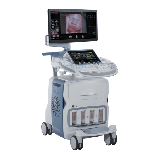
The LOGIQ E10 is a high performance digital ultrasound imaging system with total data management. The fully digital architecture of the LOGIQ E10 allows optimal usage of all scanning modes and probe types throughout the full spectrum of operating frequencies. -
Page 42: Important Conventions
Product icons ............1-10 1-3-1 Conventions used in book Model designations This manual covers the LOGIQ E10 models listed in 1-2-4 "LOGIQ E10 models covered in this manual" on page 1-4. -
Page 43: Standard Hazard Icons
5750007-1EN, R LOGIQ E10 B IRECTION ASIC ERVICE ANUAL 1-3-2 Standard hazard icons Important information will always be preceded by the exclamation point contained within a triangle, as seen throughout this chapter. In addition to text, several different graphical icons (symbols) may be used to make you aware of specific types of hazards that could possibly cause harm. - Page 44 5750007-1EN, R LOGIQ E10 B IRECTION ASIC ERVICE ANUAL Table 1-3 Standard hazard Icons Icon Meaning Pinch point 1 - 8 Section 1-3 - Important conventions...
- Page 45 5750007-1EN, R LOGIQ E10 B IRECTION ASIC ERVICE ANUAL 1-3-2 Standard hazard icons (cont’d) Other icons make you aware of specific procedures that should be followed. Table 1-4 Standard Icons that indicate that a special procedure is to be used...
-
Page 46: Product Icons
1-3-3 Product icons The following table describes the purpose and location of safety labels and other important information provided on the LOGIQ E10. Figure 1-1 Rear Panel Label Location NOTE: This machine should be used in compliance with law. Some jurisdictions restrict certain uses, such as gender determination (shown for country specific label). - Page 47 5750007-1EN, R LOGIQ E10 B IRECTION ASIC ERVICE ANUAL Table 1-5 Label Icons (Rear of Console)(Continued) Item Label/Icon Purpose/Meaning Monitor Label: How to lock system prior to transport DO NOT push the system. Use the handle to push/pull the system, e.g., DO NOT use the monitor.
- Page 48 Canada Certification label - on LOGIQ E9 equipped with Wireless Malaysian Communications and Multimedia Commission symbol. Number correspond to GE importing company (GEHC) - on LOGIQ E9 equipped with Wireless LAN ANATEL Certification label for Brazil - on LOGIQ E9 equipped with...
- Page 49 5750007-1EN, R LOGIQ E10 B IRECTION ASIC ERVICE ANUAL Table 1-5 Label Icons (Rear of Console)(Continued) Item Label/Icon Purpose/Meaning Non-Ionizing Electromagnetic Radiation Wireless LAN “ATTENTION” - Consult accompanying documents” is intended to alert the user to refer to the operator manual or other instructions when complete information cannot be provided on the label.
- Page 50 5750007-1EN, R LOGIQ E10 B IRECTION ASIC ERVICE ANUAL Table 1-5 Label Icons (Rear of Console)(Continued) Item Label/Icon Purpose/Meaning Possible shock hazard. Do not remove covers or panels. No user serviceable parts are inside. Refer servicing to qualified service personnel.
- Page 51 5750007-1EN, R LOGIQ E10 B IRECTION ASIC ERVICE ANUAL Table 1-5 Label Icons (Rear of Console)(Continued) Item Label/Icon Purpose/Meaning Every system has a unique marking for identification, the Unique Device Identification (UDI) Label. The UDI label consists of a series...
- Page 52 5750007-1EN, R LOGIQ E10 B IRECTION ASIC ERVICE ANUAL Table 1-5 Label Icons (Rear of Console)(Continued) Item Label/Icon Purpose/Meaning Op Panel To avoid injury, DO NOT place a finger, hand or any object below the operator panel when it is lowered.
-
Page 53: Product Labels On The Logiq E10 When Used In A Veterinary Environment
ANUAL 1-3-4 Product Labels on the LOGIQ E10 when used in a veterinary environment There are different handling instructions when servicing the LOGIQ E10 used in a veterinary environment. Table 1-6 Product Labels on the LOGIQ E10 in a veterinary environment... -
Page 54: Safety Considerations
Operating personnel must not remove the Ultrasound system covers. • Servicing should be performed by authorized personnel only. Only personnel who have participated in a LOGIQ E10 Training Seminar are authorized to service the equipment. DANGEROUS VOLTAGES, CAPABLE OF CAUSING DEATH, ARE PRESENT IN DANGER THIS EQUIPMENT. - Page 55 Beware that the Main Power Supply, the Power Assist batteries or Power Module and ECB may be energized even if the power is turned OFF if the cord is still plugged into the AC Outlet. Use extreme caution as long as the LOGIQ E10 is un-stable, not resting on all four WARNING WARNING casters.
- Page 56 5750007-1EN, R LOGIQ E10 B IRECTION ASIC ERVICE ANUAL 1-4-2 Human safety (cont’d) Beware of possible sharp edges on all mechanical parts. If sharp edges are WARNING WARNING encountered, the appropriate PPE should be used to reduce the risk of injury.
-
Page 57: Mechanical Safety
WARNING release pedal once disengages the swivel lock. You must depress the release pedal a second time to engage the brake. The LOGIQ E10 should NOT be moved with the Operator I/O Panel extended. Move the WARNING WARNING Operator I/O Panel to its centered and locked position. Lower the Operator I/O Panel as much as possible before moving the LOGIQ E10. - Page 58 ANUAL 1-4-3 Mechanical safety (cont’d) THE LOGIQ E10 WEIGHS 126 KG (278 LB) AND UP 135 KG (298 LB) DEPENDING ON CAUTION INSTALLED PERIPHERALS. USE CARE WHEN MOVING IT OR REPLACING ITS PARTS. FAILURE TO FOLLOW THE PRECAUTIONS LISTED BELOW COULD RESULT IN INJURY, UNCONTROLLED MOTION, AND COSTLY DAMAGE.
- Page 59 1-4-3 Mechanical safety (cont’d) Be careful not to pinch any of the cables. NOTICE Do not transport LOGIQ E10 in a vehicle without locking the casters (wheels) and securing it as CAUTION described in chapter 4. NOTE: Special care should be taken when transporting the Ultrasound system in a vehicle: •...
-
Page 60: Electrical Safety
Do not use a damaged or defective probe. • Never immerse the probe connector or adapter into any liquid. • The LOGIQ E10 has more than one type of probe port. Use the appropriate probe port designed for the probe you are connecting. Peripherals •... -
Page 61: Battery Safety
• DO NOT immerse batteries in water or allow them to get wet. CAUTION USE ONLY BATTERIES APPROVED BY GE AS SUITABLE FOR USE WITH THE LOGIQ E10 ULTRASOUND SYSTEM. CAUTION TO PREVENT BATTERIES FROM BURSTING OR IGNITING, OR FUMES FROM THE BATTERIES CAUSING EQUIPMENT DAMAGE, ALWAYS OBSERVE THE FOLLOWING PRECAUTIONS: •... -
Page 62: Label Locations
ANUAL Section 1-5 Label locations For information on label locations, refer to the appropriate version of the LOGIQ E10 Basic User Manual or the latest version of the LOGIQ E10 Release Notes. Table 1-7 Basic User Manual and Release Notes for the LOGIQ E10... -
Page 63: Dangerous Procedure Warnings
DANGEROUS VOLTAGES, CAPABLE OF CAUSING DEATH, ARE PRESENT IN DANGER THIS EQUIPMENT. USE EXTREME CAUTION WHEN HANDLING, TESTING AND ADJUSTING. IF THE COVERS ARE REMOVED FROM AN OPERATING LOGIQ E10, SOME METAL WARNING WARNING SURFACES MAY BE WARM ENOUGH TO POSE A POTENTIAL HEAT HAZARD IF TOUCHED, EVEN WHILE IN SHUT DOWN MODE. -
Page 64: Lockout/Tagout (Loto) Requirements
Control all stored and residual energy. Verify isolation: All potentially hazardous stored or residual energy is relieved. Energy Control and Power Lockout for LOGIQ E10: WARNING WARNING When servicing parts of the Ultrasound System where there is exposure to voltage greater than 30 Volts: 1. -
Page 65: Lockout/Tagout Procedure
Lockout/Tagout Procedure Lockout/Tagout Procedure TURN OFF the LOGIQ E10 and UNPLUG IT. Maintain control of the mains power plug. Wait for at least 20 seconds for capacitors to discharge and the ON/OFF button (white light on the Op Panel) to turn OFF, as there are no test points to verify isolation. -
Page 66: Returning/Shipping Probes And Repair Parts
If the purple recycling label is not used in your region, use the local recycling label. The LOGIQ E10 is not meant to be used for long-term storage of patient data or images. The user is responsible for the data on the LOGIQ E10 and a regular backup is highly recommended. -
Page 67: Electromagnetic Compatibility (Emc)
1-9-2 Compliance LOGIQ E10 conforms to all applicable conducted and radiated emission limits and to immunity from electrostatic discharge, radiated and conducted RF fields, magnetic fields and power line transient requirements. Applicable standards are: 47CFR Part 18, IEC60601-1-2:2007. -
Page 68: Electrostatic Discharge (Esd) Prevention
ESD Receptacles ESD Receptacles Battery Box side Card Cage side Risk of electrical shock. The LOGIQ E10 must be turned off. Avoid all contact with WARNING WARNING electrical contacts, conductors and components. Always use non-conductive handles designed for the removal and replacement of ESD sensitive parts. All parts that have the potential for storing energy must be discharged or isolated before making contact. -
Page 69: Customer Assistance
5750007-1EN, R LOGIQ E10 B IRECTION ASIC ERVICE ANUAL Section 1-10 Customer assistance 1-10-1 Contact information If this equipment does not work as indicated in this service manual or in the user manual, or if you require additional assistance, please contact the local distributor or appropriate support resource as listed in Table 1-11. - Page 70 5750007-1EN, R LOGIQ E10 B IRECTION ASIC ERVICE ANUAL 1-10-1 Contact information (cont’d) Table 1-11 Phone numbers for Customer Assistance LOCATION NUMBER Service TEL: 1-800-437-1171 Service Parts TEL: 1-800-558-2040 GE Healthcare Ultrasound Service Engineering Online Center TEL: 1-800-321-7937 9900 Innovation Drive (RP-2156)
- Page 71 ANUAL 1-10-2 Ultrasound system manufacturer Table 1-12 Ultrasound system manufacturer MANUFACTURER GE Healthcare - GE Medical Systems Ultrasound and Primary Care Diagnostics, LLC 9900 Innovation Drive Wauwatosa, WI 53226 Table 1-13 Authorized Representative AUTHORIZED REPRESENTATIVE This product complies with the regulatory requirement of Council Directive 93/42/EEC concerning medical devices: •...
- Page 72 5750007-1EN, R LOGIQ E10 B IRECTION ASIC ERVICE ANUAL This page was intentionally left blank. 1 - 36 Section 1-10 - Customer assistance...
- Page 73 General LOGIQ E10 requirements ........
- Page 74 LOGIQ E10 environmental requirements ........
- Page 75 ANUAL Cooling The cooling requirement for the LOGIQ E10 with monitor and onboard peripherals is up to 3070 Btu/hr. This figure does not include cooling needed for lights, people, or other equipment in the room. Each person in the room places an additional 300 Btu/hr demand on the cooling system.
- Page 76 LOGIQ E10. The LOGIQ E10 will function on voltages from 100-240 volts and 50 or 60 Hz. However, if using 220 volt power, then a center tapped power source is required.
- Page 77 LOGIQ E10 power plug If the LOGIQ E10 arrives without a power plug, or with the wrong plug, you must contact your GE dealer or the installation engineer must supply what is locally required.
- Page 78 Ultrasound machines also generate EMI. The LOGIQ E10 complies with limits as stated on the EMC label. However there is no guarantee that interference will not occur in a particular installation.
- Page 79 EMI prevention/abatement EMI Rule Detail • Keep the LOGIQ E10 at least 5 meters or 15 feet away from other EMI sources. Be aware of RF sources • Special shielding may be required to eliminate interference problems caused by high frequency, high powered radio or video broadcast signals.
- Page 80 LOGIQ E10 environmental specifications may be different than the probes. STORAGE TEMPERATURES VARY DEPENDING ON THE TYPE OF PROBE. WHEN EXPOSED TO NOTICE LARGE TEMPERATURE VARIATIONS, THE LOGIQ E10 AND PROBES SHOULD BE KEPT AT ROOM TEMPERATURE BEFORE USE. Refer to the table in "If the LOGIQ E10 is very cold or hot"...
- Page 81 The desire to use a non–listed or customer provided product or to place an approved product further from the LOGIQ E10 than the interface kit allows, presents challenges to the installation team. To avoid delays during installation, such variances should be made known to the individuals or group performing the installation at the earliest possible date (preferably prior to the purchase).
- Page 82 The LOGIQ E10 will function on voltages from 100-240 volts and 50 or 60 Hz. However, if using 220 volt power, then a center tapped power source is required.
- Page 83 Overhead light dimmer – dual level lighting (bright/dim) Emergency oxygen Suction line Dedicated power outlet – circuit breaker protected and LOGIQ E10 easily accessible 45,7 cm (1.5 ft) distance of LOGIQ E10 from wall or Network interface objects Stool Footswitch Storage for linens and equipment Examination table –...
- Page 84 External peripherals Dedicated power outlet – circuit breaker protected and Network interface easily accessible 45,7 cm (1.5 ft) distance of LOGIQ E10 from wall or Lockable cabinet ordered by GE for its software and objects proprietary manuals 2 - 12...
- Page 85 2-14. Ensure that there are no spaces in any field of the form. Entries must include: • A host name, local port number, AE Title, IP address and Net Mask for the LOGIQ E10. • The IP addresses for the default gateway and other routers at the site for ROUTING INFORMATION.
- Page 86 5750007-1EN, R LOGIQ E10 B IRECTION ASIC ERVICE ANUAL DICOM option setup requirements (cont’d) Figure 2-3 Worksheet for DICOM Network Information LOGIQ IP Address Local Port Host Name AE Title Net Mask Network Default Gateway Speed DHCP DICOM APPLICATION OTHER...
- Page 87 2-3-6 Privacy and Security Since the LOGIQ systems are integrated into your IT-network, GE wants to make sure that you are aware of the proactive measures we are taking to secure the system. For more information on privacy and security, refer to “Privacy and Security” in chapter 12 of the LOGIQ E10 Basic User Manual.
- Page 88 5750007-1EN, R LOGIQ E10 B IRECTION ASIC ERVICE ANUAL Patient Vicinity UL60601-1 (USA) 2.12.20DV (UL60601-1:2003) In area in which patients are normally cared for, the patient vicinity is the space with surfaces likely to be contacted by the patient or attendant who can touch the patient. This encloses a space within the room 1.83 m (6 ft.) beyond the perimeter of the bed (examination table, dental chair, treatment booth,...
- Page 89 5750007-1EN, R LOGIQ E10 B IRECTION ASIC ERVICE ANUAL Patient Environment IEC60601-1 (IEC60601-1-1) and ANSI AAMI ES60601-1 Sub Clause 2.202 and figure 201 (IEC60601-1-1:2000) Sub Clause 3.79 and figure A.9 (IEC60601-1:2005 and ANSI AAMI ES60601-1:2005) Such an area is an environment in which medical diagnosis, monitoring or treatment is carried out. It is very difficult to attach unique dimensions to the PATIENT ENVIROMENT.
- Page 90 5750007-1EN, R LOGIQ E10 B IRECTION ASIC ERVICE ANUAL This page was intentionally left blank. 2 - 18 Section 2-3 - Facility needs...
- Page 91 Section 3-1 Overview 3-1-1 Purpose of this chapter This chapter contains information needed to set up the LOGIQ E10. Also included in this section are guidelines for transporting the unit to a new site. 3-1-2 Contents in this chapter Overview............. 3-1 Setup reminders .
- Page 92 DO NOT WEAR THE ESD WRIST STRAP WHEN YOU WORK ON LIVE CIRCUITS AND MORE CAUTION THAN 30 V PEAK IS PRESENT. DO NOT OPERATE THE LOGIQ E10 UNLESS ALL BOARD COVERS AND FRAME PANELS ARE CAUTION SECURELY IN PLACE. LOGIQ E10 PERFORMANCE AND COOLING REQUIRE THIS.
- Page 93 OPERATOR MANUAL(S) CAUTION THE USER MANUAL(S) SHOULD BE FULLY READ AND UNDERSTOOD BEFORE OPERATING THE LOGIQ E10 AND KEPT NEAR THE LOGIQ E10 FOR QUICK REFERENCE. ACOUSTIC OUTPUT HAZARD CAUTION ALTHOUGH THE ULTRASOUND ENERGY TRANSMITTED FROM THE LOGIQ E10 PROBE IS WITHIN AIUM/NEMA STANDARDS, AVOID UNNECESSARY EXPOSURE.
- Page 94 Receiving the LOGIQ E10........
- Page 95 Before cutting the straps, check the tilt indicator to make sure it has not been triggered. If triggered, report it to the carrier. If not, then cut the straps around the crate. Chapter 3 LOGIQ E10 Setup 3 - 5...
- Page 96 5750007-1EN, R LOGIQ E10 B IRECTION ASIC ERVICE ANUAL LOGIQ E10 Transportation Box Label The LOGIQ E10 Transportation Box Label is located on the transportation box. Table 3-2 LOGIQ E10 Transportation Box Labeling SYMBOL DEFINITION/COMMENTS RECYCLING Recyclable Wood RECYCLING China Specific...
- Page 97 STEP TASK Write “Damage In Shipment” on ALL copies of the freight or express bill BEFORE delivery is accepted or “signed for“ by a GE representative or hospital receiving agent. Report the damage to the carrier. • Whether noted or concealed, damage MUST be reported to the carrier immediately upon discovery, or in any event, within 14 days after receipt, and the contents and containers held for inspection by the carrier.
- Page 98 ERVICE ANUAL 3-3-5 Unpacking the LOGIQ E10 The instruction manual describes the best method for unpacking the LOGIQ E10 Ultrasound scanning System. Images are ONLY for reference; wear proper PPE when handling packaging (gloves, safety shoes, etc.). Table 3-4 Uncrating Instructions...
- Page 99 Remove the plastic foil from around the LOGIQ E10. On the front of the pallet, loosen the ratchet (will be called out) and unhook the strap from the LOGIQ E10. Procedure continues... Chapter 3 LOGIQ E10 Setup 3 - 9...
- Page 100 Corresponding Graphic From the back of the pallet, unhook the strap (will be called out) from the other end of the LOGIQ E10. Attach the wooden ramp to the rear of the pallet base and fasten the Velcro straps. Using two people, pull the unit down the ramp on the back off the pallet.
- Page 101 IRECTION ASIC ERVICE ANUAL 3-3-6 Packing materials - recycling information The packing materials for the LOGIQ E10 are recyclable: • The transportation box is made of cardboard. • Lever lockings (hinges) are made of zinc plated steel. • The inner reinforcements are made of Ethafoam (Polyethylene foam).
- Page 102 3-3-9 Physical inspection Verify that the LOGIQ E10 arrived intact (visual inspection). If the LOGIQ E10 has been damaged, please refer to “Damage in Transportation “on page "Damage in transportation" on page 3-7 in the beginning of this manual.
- Page 103 For rating label location, see Figure 3-4 "Rear Cover Label and Rating Label Locations" on page 3-14. Figure 3-2 Rear Cover Label with ETL Label Figure 3-3 Rating Label - LOGIQ E10 Chapter 3 LOGIQ E10 Setup 3 - 13...
- Page 104 5750007-1EN, R LOGIQ E10 B IRECTION ASIC ERVICE ANUAL Rear cover label (A) and rating label (B) locations Figure 3-4 Rear Cover Label and Rating Label Locations 3 - 14 Section 3-3 - Receiving and unpacking the equipment...
- Page 105 This LOGIQ E10 has been designed to minimize the effects of Electro-Magnetic Interference (EMI). Many of the covers, shields, and screws are provided primarily to protect the LOGIQ E10 from image artifacts caused by this interference. For this reason, it is imperative that all covers and hardware are installed and secured before the LOGIQ E10 is put into operation.
- Page 106 LOGIQ E10 specifications........
-
Page 107: Electrical Specifications
Verification of the LOGIQ E10 voltage setting Verify that the mains voltage specified for the LOGIQ E10 is available on-site. The voltage setting for the LOGIQ E10 is found on the rating label on the back of the LOGIQ E10 on lower rear frame. -
Page 108: Connections On The I/O Rear Panel
RJ-45 modular, 8-pin Ethernet S-Video HDMI port Connect USB Flash Drive Refer to “USB Hard Disk Drive and USB Flash Drive” in Chapter 9 of the LOGIQ E10 Basic User Manual for more information. 3 - 18 Section 3-4 - Completing the setup... -
Page 109: Connections On The Patient I/O Panel
ANUAL 3-4-5 Connections on the Patient I/O panel Connect ECG Refer to “Patient Cardiac and ECG Connections” in Chapter 3 of the LOGIQ E10 Basic User Manual for more information. 3-4-6 Connecting Probes Probes can be connected at any time, whether the LOGIQ E10 is on or off. - Page 110 5750007-1EN, R LOGIQ E10 B IRECTION ASIC ERVICE ANUAL To disconnect a probe: 1.) Select a different probe or freeze the image before removing a probe in order to avoid disconnecting a live probe. 2.) Rotate the lock handle counter-clockwise to the horizontal position to unlock the connector.
-
Page 111: Power On/Boot Up
Do not cycle the circuit breaker ON-OFF-ON in less than five seconds. When turning OFF the circuit breaker, WAIT until the ON/OFF button is no longer lit. The LOGIQ E10 should de- energize completely before turning the circuit breaker ON. - Page 112 LOGIQ E10. 4.) Connect the female plug of the power cable to the power inlet at the rear of the LOGIQ E10. 5.) Lock the plug in position with the retaining clamp (ACC clamp).
- Page 113 Figure 3-9 ON/OFF button You should hear a click from the relays in the AC power and the LOGIQ E10 is ready to boot. This indicates that there is power to the PS, but the LOGIQ E10 is OFF.
-
Page 114: Password Policies
5750007-1EN, R LOGIQ E10 B IRECTION ASIC ERVICE ANUAL 3-4-8 Password Policies To create password policies: 1.) Navigate to Utility > Admin > Logon. 2.) Select Enable Password Policies. The system prompts the user for a password at logon. Figure 3-10 Password Policies Window 3.) Under Password Policies, use the drop down selection beside each feature to set the rules for... - Page 115 The system administrator may also remove a user. Highlight the user Id in the list, select Remove to mark the user as inactive and then select Remove again to remove user from the list. Chapter 3 LOGIQ E10 Setup 3 - 25...
- Page 116 5750007-1EN, R LOGIQ E10 B IRECTION ASIC ERVICE ANUAL To use groups: You can use predefined groups or create new groups. Assign groups to a user from Users and under Group Memberships. 1.) Navigate to Utility > Admin > Groups.
- Page 117 Auto LOGON only works when password policies are disabled and if there is no password assigned to the user. 1.) Navigate to Utility > Admin > Logon. 2.) Select Auto Logon. The system will start by using the ID of the last operator. Chapter 3 LOGIQ E10 Setup 3 - 27...
-
Page 118: Disc Encryption
5750007-1EN, R LOGIQ E10 B IRECTION ASIC ERVICE ANUAL 3-4-9 Disc Encryption Patient Data Disc Encryption Bitlocker Drive Encryption uses Advanced Encryption Standard (AES) with configurable key lengths of 256 bits. To enable disk encryption: 1.) Navigate to Utility > Admin > Disk Encryption. - Page 119 After the disk is encrypted, you will be required to unlock the disk at each startup of the system. The unlock dialog box will appear when the new patient or print button is pushed. Chapter 3 LOGIQ E10 Setup 3 - 29...
- Page 120 5750007-1EN, R LOGIQ E10 B IRECTION ASIC ERVICE ANUAL 16.)Use one of the methods to access/unlock the system: Connect a USB Flash Drive to the system. Select Password and type the password in the field. Select Recovery key and then type in the recovery key in the field.
-
Page 121: Login
After you have established your password, follow these steps to login. 1.) Type your user name in the Operator field. 2.) Type your password in the Password field. 3.) Press OK to login, or Cancel to cancel login. Chapter 3 LOGIQ E10 Setup 3 - 31... - Page 122 5750007-1EN, R LOGIQ E10 B IRECTION ASIC ERVICE ANUAL To change your password: You can change your password when first logging onto the system. 1.) Type your name in the Operator field. 2.) Press the Change Password button. The Change Password pop-up displays.
-
Page 123: Logoff/Power Shut Down
Use this button to log off the current user. The LOGIQ E10 remains ON and ready for a new user to log on. If this button is dimmed, it indicates that no user is logged on to the LOGIQ E10 at the moment. •... -
Page 124: Complete Power Down
The back end will first turn off the LOGIQ E10 activity and print the message “Please wait - Shutdown in progress” in the display on the operator panel. Next, it starts to shut down. The time to turn down the LOGIQ E10, including the back end, may vary from 10 seconds up to approximately 1 minute. - Page 125 LOGIQ E10 configuration ........
- Page 126 LOGIQ E10 B IRECTION ASIC ERVICE ANUAL 3-5-3 Optional Peripherals/Peripheral Connection Approved Internal Peripherals (Optional) This list covers the internal peripherals available for the LOGIQ E10. • 4D Option USB Flash Drive • Black and White Printer • CW Option •...
- Page 127 Software Options Configuration Software Option Installation A password (Software Option String) enables a software option or a combination of software options. This password is specific for each LOGIQ E10. Installing a Software Option NOTE: Before you install a software option, you must login.
- Page 128 Figure 3-24 System Admin Window - Add button 6.) Select the Add button. INCORRECT PASSWORD ENTRY WILL RESULT IN LOSS OF SYSTEM OPTIONS. CAUTION IF PASSWORD IS INCORRECT, PLEASE CONTACT YOUR LOCAL GE SERVICE REPRESENTATIVE OR THE ONLINE CENTER. 3 - 38 Section 3-5 - Configuration...
- Page 129 There is an Import button on the Utility > Admin > System Admin menu. 8.) Press Save to save the new setting. 9.) Restart to save and activate the settings and adjustments you have done so far. Chapter 3 LOGIQ E10 Setup 3 - 39...
- Page 130 5750007-1EN, R LOGIQ E10 B IRECTION ASIC ERVICE ANUAL Section 3-6 Setup paperwork NOTE: During and after setup, the documentation (for example, CDs with documentation, user manuals, and installation manuals) for the peripheral units must be kept as part of the original system documentation.
- Page 131 Section 4-1 Overview 4-1-1 Purpose of this chapter This chapter provides procedures for quickly checking major functions of the LOGIQ E10 Ultrasound system and diagnostics instructions using the built-in service software. 4-1-2 Contents in this chapter Overview............. 4-1 Functional checks .
- Page 132 5750007-1EN, R LOGIQ E10 B IRECTION ASIC ERVICE ANUAL Section 4-2 Functional checks Contents in this section 4-2-1 General procedures ........... . 4-3 4-2-2 Overview .
-
Page 133: General Procedures
General procedures THE ULTRASOUND SYSTEM REQUIRES ALL COVERS NOTICE Operate the LOGIQ E10 only when all board covers and frame panels are securely in place. The covers are required for safe operation, good system performance and cooling purposes. Table 4-1... -
Page 134: Overview
DO NOT POWER SHUT DOWN until 4-2-4 ALL functional checks have been performed LOGIQ E10 Basic Service Manual, Direction 5750007-1EN, In addition: Perform the following Functional Rev. 1. Leakage Current measured at (record the value) and Checks if the Option was or Options were removed meets allowable limits. - Page 135 Plug in the ECG cables with nothing attached so they pick up noise. LOGIQ E10 Basic Service Manual, Direction 5750007-1EN, Diagnostics Rev. 1. Leakage Current measured at (record the value) and meets allowable limits. Equipment passed all required checks Diagnostics and is ready for use.
-
Page 136: Power On/Boot Up
OPERATE THIS ULTRASOUND SYSTEM ONLY WHEN ALL BOARD COVERS AND FRAME PANELS ARE SECURELY IN PLACE. THE COVERS ARE REQUIRED FOR SAFE OPERATION, GOOD SYSTEM PERFORMANCE AND COOLING PURPOSES. Use only power supply cords, cables and plugs provided by or designated by GE. NOTICE NOTE: Do not cycle the Circuit Breaker ON-OFF-ON in less than five (5) seconds. - Page 137 NOTE: The LOGIQ E10 will function on Voltages from 100-240 Volts and 50 or 60 Hz. However, if using 220 volt power, then a center tapped power source is required. 1.) Ensure that the wall outlet is of appropriate type, and that the Circuit Breaker is turned off.
- Page 138 1.) Switch ON the Mains Power Circuit Breaker at the rear of the LOGIQ E10. The ON/OFF button will become white. You should hear a “click” from the relays in the AC Power and the LOGIQ E10 is ready to boot. The ON/ OFF button will remain white.
-
Page 139: Power Shut Down
LOGIQ E10 B IRECTION ASIC ERVICE ANUAL 4-2-4 Power SHUT DOWN When you switch OFF the LOGIQ E10, the Ultrasound system performs an automatic Shutdown sequence. Table 4-3 SYSTEM - EXIT menu Steps Corresponding Graphic The SYSTEM - EXIT menu, used when... -
Page 140: Top Console Checks
5750007-1EN, R LOGIQ E10 B IRECTION ASIC ERVICE ANUAL 4-2-5 Top Console checks Alphanumeric Keyboard Checks Select comments and type different A/N keys to confirm keyboard functionality. Footswitch 1.) Plug in the footswitch. 2.) Select Utility -> Application. You should see the footswitch programming options for Left, Middle and Right switches. - Page 141 The vertical displacement of the Top Console is motor driven. The control buttons are located between the handles. Power ON the LOGIQ E10 before performing the following steps. Table 4-4...
- Page 142 5750007-1EN, R LOGIQ E10 B IRECTION ASIC ERVICE ANUAL Main Monitor Positions and Lock Figure 4-4 Main Monitor Positions - Ergotron Arm Tilt a. No Collision 1. Vertical Travel = 150mm b. Approximately 20º (based on Pan Arm Off-set) c. 85º-90º...
- Page 143 5750007-1EN, R LOGIQ E10 B IRECTION ASIC ERVICE ANUAL Operator I/O Movement - Main Monitor Check that the monitor functions as described below Table 4-5 Main Monitor Platform Maneuverability Checks Step Task Note(s) Use both hands, one at the top of the Main Monitor and...
-
Page 144: Brakes And Direction Lock Functional Checks
5750007-1EN, R LOGIQ E10 B IRECTION ASIC ERVICE ANUAL 4-2-6 Brakes and Direction Lock Functional Checks Table 4-6 Brakes and Direction Lock Functional Checks Steps Corresponding Graphic Front Brakes and Direction Locks Check that the Front brakes and direction locks function. -
Page 145: Operation Checks
ANUAL 4-2-7 Operation checks Basic Controls Figure 4-6 LOGIQ E10 Trackball Area Different functions can be assigned to the Trackball depending of the current active mode. The Trackball area consist of: • The Trackball: used as a cursor control in acquisition mode, scrolling control in freeze and as a selection tool (like a mouse cursor) in post-processing mode. - Page 146 ANUAL Recommended Test Phantoms GE recommends the RMI 430GS phantom is preferred, but it is not required. It is the most current phantom recommended to our field service personnel and provides the necessary targets and extended life necessary for consistent Ultrasound system testing.
- Page 147 ANUAL Probe/Connectors Checks NOTE: Probes can be connected at any time, whether the LOGIQ E10 is ON or OFF. To connect a probe 1.) Place the probe's carrying case on a stable surface and open the case. 2.) Carefully remove the probe and unwrap the probe cable.
- Page 148 Depending on probe availability, choose the preset application shown below. The LOGIQ E10 probes are ONLY approved for use in the applications listed in the LOGIQ E10 Basic User Manual, Chapter 11, or the appropriate LOGIQ E10 Release Notes. See: Section 1-5 "Label locations"...
- Page 149 ASIC ERVICE ANUAL B-Mode Checks (cont’d) Probe Indications for Use See On-line Help or refer to the appropriate version of the LOGIQ E10 Basic User Manual, Chapter 11. See: Section 1-5 "Label locations" on page 1-26. Preparations You may use a phantom (optional) when doing these tests.
- Page 150 Section 3-4-6 "Connecting Probes" on page 3-19 for info about connecting the probes. For available probes, see: On-line Help or refer to the appropriate version of the LOGIQ E10 Basic User Manual. See: Section 1-5 "Label locations" on page 1-26.
- Page 151 Color Flow may be selected both from B-Mode, or from M mode, or a combination of these. For information, refer to the appropriate version of the LOGIQ E10 Basic User Manual, Chapter 5, or the appropriate LOGIQ E10 Release Notes.
- Page 152 By using an ordinary probe, you can first bring up a B-Mode picture for navigation purpose and then add Doppler. For information, refer to the appropriate version of the LOGIQ E10 Basic User Manual, Chapter 5, or the appropriate LOGIQ E10 Release Notes.
- Page 153 ASIC ERVICE ANUAL Cineloop Checks For complete information, refer to the appropriate version of the LOGIQ E10 Basic User Manual, Chapter 5, or the appropriate LOGIQ E10 Release Notes. See: Section 1-5 "Label locations" on page 1-26. To Activate CINE 1.) Press Freeze, then roll the Trackball to activate CINE.
- Page 154 IRECTION ASIC ERVICE ANUAL Removable Media Refer to the appropriate version of the LOGIQ E10 Basic User Manual, or the appropriate LOGIQ E10 Release Notes. See: Section 1-5 "Label locations" on page 1-26 to perform the following tasks: • Using Removable Media •...
- Page 155 5750007-1EN, R LOGIQ E10 B IRECTION ASIC ERVICE ANUAL Basic Measurements NOTE: The following instructions assume that you first scan the patient and then press Freeze. Check Distance and Tissue Depth Measurement 1.) Press Measure once to display an active caliper.
- Page 156 Multi Image Checks For information on the Ultrasound system’s different modes as well as expected results, refer to the appropriate version of the LOGIQ E10 Basic User Manual, Chapter 5, or the appropriate LOGIQ E10 Release Notes. See: Section 1-5 "Label locations" on page 1-26.
- Page 157 ERVICE ANUAL ECG Checks Introduction The ECG capability on this LOGIQ E10 is intended as a trigger for measurements, but can also be viewed on the screen. Parts needed ECG Harness, for P/Ns, see: Section, Options. ECG Pads, (3 pc)
- Page 158 5750007-1EN, R LOGIQ E10 B IRECTION ASIC ERVICE ANUAL Section 4-3 Site Log Table 4-11 Site Log DATE SERVICE PERSON PROBLEM COMMENTS 4 - 28 Section 4-3 - Site Log...
- Page 159 LOGIQ E10 description ........
-
Page 160: Logiq E10 Models
5750007-1EN, R LOGIQ E10 B IRECTION ASIC ERVICE ANUAL Section 5-2 LOGIQ E10 models Table 5-1 LOGIQ E10 Models MODEL SOFTWARE DESCRIPTION NUMBER VERSION LOGIQ E10, 5935000E10 R1.x.x 100-240 VAC 5 - 2 Section 5-2 - LOGIQ E10 models... -
Page 161: Logiq E10 Description
LOGIQ E10 general description ........ - Page 162 LOGIQ E10 general description LOGIQ E10 is a digital beamforming Ultrasound system. Signal flow travels from the Probe Connector Panel to the Front End Electronics, then to the ECB (LOGIQ E10 Carrier Board), and finally, the results are displayed on the monitor System configuration is stored on the hard drive and all necessary software is loaded from the hard drive on power up.
-
Page 163: Software Overview
Purpose of this section ..........5-5 5-4-2 LOGIQ E10 Base Load Image and Application Software ......5-6 5-4-3 Electronic media . - Page 164 Windows 10 Embedded Contains all necessary drivers to support devices and peripherals approved for this product Application Software Contains customized Software to perform all functions and features for the LOGIQ E10 • Software Location: Software resides in the internal hard drive...
- Page 165 5750007-1EN, R LOGIQ E10 B IRECTION ASIC ERVICE ANUAL 5-4-3 Electronic media Accessing Documentation Via a Windows PC To view user documentation on a Windows PC: 1.) Insert the media into the media drive. 2.) Open the media drive on your desktop.
- Page 166 5750007-1EN, R LOGIQ E10 B IRECTION ASIC ERVICE ANUAL 5-4-4 Log File Content Uncompressing the log files provides a subdirectory with the results. 1.) SysConfig.csv – Contains serial number, hardware info, software version, etc. 2.) log/ExceptionTrace – subdirectory contains text file with call stack of system crashes 3.) log/DL –...
- Page 167 Remote Control App • Camera App To link to the device: 1.) Connect the device to the LOGIQ E10 via dongle. 2.) Scan for devices. 3.) Connect to the device. Remote Control App Via the Remote Control App, you will be able to adjust the following controls: •...
-
Page 168: Service Desktop
The Service Desktop is an interface that provides access to system information, status and diagnostics. The Service Desktop has different content or views depending on the access level. The access level is determined by the user profile as well as the service options enabled on the LOGIQ E10. •... - Page 169 5750007-1EN, R LOGIQ E10 B IRECTION ASIC ERVICE ANUAL Table 5-3 User Level of the Service Desktop Basic View Class C View Levels Main Main Sub- Service Service Service Menus menus Simple Advanced Expert Software Reload Reset Patient Database Clean...
-
Page 170: Front End
5750007-1EN, R LOGIQ E10 B IRECTION ASIC ERVICE ANUAL Section 5-6 Front End 5-6-1 Purpose of this section The intention with this section is to give you a brief overview of the Front End configuration used on LOGIQ E10. Contents in this section 5-6-1 Purpose of this section . - Page 171 5750007-1EN, R LOGIQ E10 B IRECTION ASIC ERVICE ANUAL 5-6-2 Card Rack General description The “Card Rack” houses all the transmit, receive and processing circuit boards. Chapter 5 Components and Functions (Theory) 5 - 13...
-
Page 172: Back End
5750007-1EN, R LOGIQ E10 B IRECTION ASIC ERVICE ANUAL Section 5-7 Back End 5-7-1 Purpose of this section The intention with this section is to give you a brief overview of the Back End configuration used on LOGIQ E10. Contents in this section 5-7-1 Purpose of this section . - Page 173 5-7-2 General Description The LOGIQ E10 Carrier Board (ECB) is a single board computer built from a COM Express module fitted into customized rack. Its main function is to be the central processing unit of the Ultrasound system, controlling all the functionality, user interface and connectivity of the scanner.
- Page 174 IRECTION ASIC ERVICE ANUAL ECB LEDs Figure 5-2 ECB LEDs Table 5-4 LOGIQ E10 ECB LEDs Mark Definition Color - Normal Color: Cause - OFF: AC power off or Main PS 5Volt standby power failure - Yellow/amber: STANDBY mode POWER_ON - Green: Working;...
- Page 175 Z (Software Repository and additional files for Software Reload) partitions of the HDD. No patient data is stored on the SSD. Location of the SSD in the LOGIQ E10 Figure 5-3 SSD location Chapter 5 Components and Functions (Theory)
-
Page 176: Backplane
Backplane 5-8-1 Purpose of this section The intention with this section is to give you a brief overview of the Backplane used on LOGIQ E10. Contents in this section 5-8-1 Purpose of this section ..........5-18 5-8-2 Backplane . - Page 177 ANUAL 5-8-2 Backplane The LOGIQ E10 Backplane is part of an Ultrasound system, capable of processing 192 ultrasound channels concurrently. It functions as interconnect for the different boards and Options in the LOGIQ E10 Hard Ware platform. Chapter 5 Components and Functions (Theory)
-
Page 178: Top Console With Main Monitor And Operator Panel
Transporting LOGIQ E10 ........ -
Page 179: Power Distribution
Power distribution 5-10-1 Purpose of this section The power distribution within the LOGIQ E10 is described in this section. Contents in this section 5-10-1 Purpose of this section ..........5-21 5-10-2 Main Power Supply. - Page 180 • Back End An inrush current limiter reduces the peak input current when the LOGIQ E10 is switched on. An EMI filter helps to reduce EMI to acceptable levels. The mains cord has plugs in both ends. A female plug connects to the scanner and a male plug to the wall outlet.
- Page 181 5750007-1EN, R LOGIQ E10 B IRECTION ASIC ERVICE ANUAL General description Figure 5-4 Main Power Supply location (rear of LOGIQ E10) Chapter 5 Components and Functions (Theory) 5 - 23...
- Page 182 5750007-1EN, R LOGIQ E10 B IRECTION ASIC ERVICE ANUAL Temperature Control The Main Power Supply is equipped with an internal fan with variable speed for temperature control. Both the temperature of the air entering the power supply and leaving the power supply are measured.
-
Page 183: Air Flow Control
Location in the LOGIQ E10 There are three air strainers/filters: One located on the rear of the LOGIQ E10 and one located on each side panel, near the bottom in a recessed feature. Refer to Chapter 8 for more information. -
Page 184: Casters And Brakes Description
ASIC ERVICE ANUAL Section 5-12 Casters and Brakes description The front brake is used for everyday use; the back brake is ONLY used to transport the LOGIQ E10. Table 5-5 Casters and Brakes direction Steps Corresponding Graphic Front Brakes and Direction Locks Check that the Front brakes and direction locks function. -
Page 185: Options And Peripherals Descriptions
Options and Peripherals descriptions 5-13-1 Purpose of this section The Options and Peripherals within the LOGIQ E10 is described in this section. Contents in this section 5-13-1 Purpose of this section ..........5-27 5-13-2 Internal Hardware Options and Peripherals . - Page 186 5750007-1EN, R LOGIQ E10 B IRECTION ASIC ERVICE ANUAL 5-13-3 External peripherals (See: 3-5-3 "Optional Peripherals/Peripheral Connection" on page 3-36) • Bin(s) Option • USB Flash Drives • Color Inkjet Printer • USB Hard Disk Drives • Footswitch • Dicom Printers •...
- Page 187 ERVICE ANUAL Section 5-14 Product manuals The information needed to use and service the LOGIQ E10 scanner is collected in the documents described in this section. NOTE: Dates on screenshots are represented in MM/DD/YYYY format throughout the manual. Information on how to change the LOGIQ E10’s date can be found in Customizing Your System, Chapter 10 in the LOGIQ E10 User Manual/User Guide.
- Page 188 5750007-1EN, R LOGIQ E10 B IRECTION ASIC ERVICE ANUAL This page was intentionally left blank. 5 - 30 Section 5-14 - Product manuals...
- Page 189 6-1-1 Purpose of this chapter This section describes how to adjust the LOGIQ E10. Contents in this chapter Overview............. 6-1 Monitor adjustments .
- Page 190 5750007-1EN, R LOGIQ E10 B IRECTION ASIC ERVICE ANUAL Section 6-2 Monitor adjustments 6-2-1 Purpose of this section This section describes how to adjust the Monitor for optimal performance. Contents in this section 6-2-1 Purpose of this section ..........6-2 6-2-2 Access to Adjustments .
- Page 191 • Contrast 40% • Room Setting: Dark For complete information, refer to the appropriate version of the LOGIQ E10 Basic User Manual Chapter 3, or the appropriate LOGIQ E10 Release Notes. See: Section 1-5 "Label locations" on page 1-26. Chapter 6 Service Adjustments...
- Page 192 5750007-1EN, R LOGIQ E10 B IRECTION ASIC ERVICE ANUAL 6-2-3 Monitor Adjustment Procedure Table 6-1 Room Profile Table Brightness/Contrast Room Profile 22 inch OLED 50/40 Dark 50/65 Semi-Dark 50/100 Light User-adjustable Brightness/Contrast User Defined 6 - 4 Section 6-2 - Monitor adjustments...
- Page 193 Push the mode button once to display the popup and select Unlock or wait for the timeout. Touch Panel can be adjusted 10% to 100%. For complete information, refer to the appropriate version of the LOGIQ E10 Basic User Manual, Chapter 3 or the appropriate LOGIQ E10 Release Notes. See: Section 1-5 "Label locations"...
- Page 194 5750007-1EN, R LOGIQ E10 B IRECTION ASIC ERVICE ANUAL 6-2-4 Advanced Monitor Adjustments Review Gamma Setting Gamma settings can be adjusted in two ways, with or without DICOM Gray Scale Standard Display Function (GSDF) enabled.GSDF-compliant with all contrast settings, but not all brightness settings.
- Page 195 5750007-1EN, R LOGIQ E10 B IRECTION ASIC ERVICE ANUAL Test patterns are available to aid in evaluating the display visually and quantitatively. Table 6-2 Test Patterns Test Pattern Description Corresponding Graphic Confirm that you can clearly see all of the different gradations of the grayscale in each gray cell.
- Page 196 5750007-1EN, R LOGIQ E10 B IRECTION ASIC ERVICE ANUAL Table 6-2 Test Patterns Test Pattern Description Corresponding Graphic Luminance for different grayscale levels. LN-1 Usually, the facility’s Biomed Engineer tests each gray level map on the monitor from LN-1 to LN-18 with a light meter and then graphs these on a scale to ensure that the curve falls within the GSDF’s standard.
- Page 197 Contrast. Confirm that you can detect the circles within the square grayscale boxes. Used for Luminance response For complete information, Refer to the appropriate version of the LOGIQ E10 Basic User Manual, Chapter 3. See: Section 1-5 "Label locations" on page 1-26. Chapter 6 Service Adjustments...
- Page 198 Purpose of this section This section describes how to adjust the Monitor Arm and/or Monitor range of motion for optimal performance. Table 6-3 LOGIQ E10 Monitor Arm Ergotron Arm Adjustments available Monitor Range of motion and Monitor Arm vertical adjustment.
- Page 199 5750007-1EN, R LOGIQ E10 B IRECTION ASIC ERVICE ANUAL 6-3-3 Main Monitor Arm and Monitor Friction Adjustment - Ergotron Arm Monitor Arm Vertical adjustment If the Monitor rises or falls when it is released, perform a Vertical adjustment. Table 6-5...
- Page 200 5750007-1EN, R LOGIQ E10 B IRECTION ASIC ERVICE ANUAL Monitor Arm Vertical adjustment - Ergotron Arm If the Monitor is too loose or too tight when it is tilted, perform a Tilt adjustment. Table 6-6 Monitor Tilt adjustment - Ergotron Arm...
- Page 201 Operator Panel movement 6-4-1 Purpose of this section The Operator Panel movement within the LOGIQ E10 is described in this section. Contents in this section 6-4-1 Purpose of this section ..........6-13 6-4-2 Adjusting the Z-Mechanism .
- Page 202 5750007-1EN, R LOGIQ E10 B IRECTION ASIC ERVICE ANUAL 6-4-2 Adjusting the Z-Mechanism Table 6-8 Adjusting the Z-Mechanism Steps Corresponding Graphic There are no adjustments for the OP Z-Mechanism Manual adjustment lever vertical movement. The Z-Mechanism can be manually repositioned in the event the drive gear is disconnected or has failed.
- Page 203 5750007-1EN, R LOGIQ E10 B IRECTION ASIC ERVICE ANUAL 6-4-3 Adjusting the XY Locking Mechanism Table 6-9 Adjusting the XY Locking Mechanism Steps Corresponding Graphic This procedure is intended to adjust the XY Adjustment for Operator Panel locking mechanism for the XY Assembly.
- Page 204 5750007-1EN, R LOGIQ E10 B IRECTION ASIC ERVICE ANUAL 6-4-4 Using the Park Lock Properly It is important to inform a customer of the following if they are experiencing problems with the XY park lock function. Be sure to: Table 6-10...
- Page 205 5750007-1EN, R LOGIQ E10 B IRECTION ASIC ERVICE ANUAL Section 6-5 Adjust time-out for DICOM servers If you are experiencing problems with slow responses from DICOM servers, increase the time-out in the DICOM server properties dialog. (Utility -> Connectivity -> Service -> Properties -> Maximum Retries and Timeout.)
- Page 206 5750007-1EN, R LOGIQ E10 B IRECTION ASIC ERVICE ANUAL This page was intentionally left blank. 6 - 18 Section 6-6 - Volume Navigation Calibration Procedure...
- Page 207 5750007-1EN, R LOGIQ E10 B IRECTION ASIC ERVICE ANUAL Chapter 7 Diagnostics/Troubleshooting Section 7-1 Overview 7-1-1 Purpose of this chapter This chapter describes how to setup and run the tools and software that help maintain image quality and system operation. Basic host-, system-, and board-level diagnostics are run whenever power is applied.
- Page 208 Purpose of this section Problem images and system data (logs) can be acquired at the LOGIQ E10 or through service remote connectivity. Use this data to perform service at the LOGIQ E10 or to send it back to the manufacturer for analysis.
- Page 209 Collecting vital system information The following information is necessary to properly analyze data or images being reported as a malfunction or a LOGIQ E10 being returned to the manufacturer: NOTE: This information is normally collected with Alt+D or Gather Logs.
- Page 210 ANUAL 7-2-3 Collecting a screen capture with logs If the LOGIQ E10 malfunctions, simultaneously press the Alt+D keys. Alt+D is available at all times and collects a screen capture of the image monitor, user-defined presets, and these logs: • Keyboard Shadow Log (protected information) •...
- Page 211 The Export/Service directory is only used for remote service and is not intended for images or report storage use. For a CD/DVD, the LOGIQ E10 automatically formats an un formatted disk, gathers logs and writes it out to the disk.
- Page 212 5750007-1EN, R LOGIQ E10 B IRECTION ASIC ERVICE ANUAL 7-2-3 Collecting a screen capture with logs (cont’d) Double check the media that you made to ensure it contains the file. An example is shown in Figure 7-2 "Example of Zipped Trouble Image and Logs File" on page 7-6.
- Page 213 To collect a trouble image you need to enable Transfer Images (captured without patient information) to GE under ADMIN > System Admin. To collect the image, press the P1 key (copy to hard drive). This places an unidentified .jpeg image in the D:\Log \DL folder.
- Page 214 Microsoft Message Analyzer to convert the output, and then Wireshark (or some other network sniffer) to analyze it. To troubleshoot network capture logs: 1.) On the LOGIQ E10, run the Network Capture utility to generate .etl and .cab files for analysis. For more information, see "Network Capture" on page 7-29.
- Page 215 5750007-1EN, R LOGIQ E10 B IRECTION ASIC ERVICE ANUAL 6.) To export the .etl file to .cab, select File > Save As and then select Save As or Export. If the network capture was of a wireless connection, Microsoft Message Analyzer creates a .pcap file that does not have any of the packets and is probably useless.
- Page 216 Service Expert, Pro, and Advanced access (Class C) Local – Depending on the purchase level, includes an option string to control access. • GE Service access (Class M) and an SSA key. For users with local Service Access privileges, this level provides unrestricted access to all Service desktop widgets and utilities. •...
-
Page 217: Disruptive Mode
Additionally, the ability to enable Disruptive mode depends on the logged in user. • Local user – a user locally logged into the machine will be able to set the LOGIQ E10 to Disruptive mode or allow a Disruptive mode request from a remote user through the Service desktop. The local user must have Authorize Remote Service Access to allow Disruptive mode. -
Page 218: Licenses
5750007-1EN, R LOGIQ E10 B IRECTION ASIC ERVICE ANUAL 7-3-4 Licenses With Service Basic Access (Class A), these are the available options: • HOME • Utilities Change Password Data Transfer Delete Files Gather Logs Network Capture SSA License Third Party Licenses •... - Page 219 5750007-1EN, R LOGIQ E10 B IRECTION ASIC ERVICE ANUAL With GE Service access (Class M) and an SSA key, these are the available options: • HOME • Diags • DICOM • Utilities Change Password (not available through a remote connection)
-
Page 220: Home
5750007-1EN, R LOGIQ E10 B IRECTION ASIC ERVICE ANUAL 7-3-5 Home Home configurations vary depending upon the purchased service level. Figure 7-6 Home with Class C and Class M Access Figure 7-7 Home with Class A Access For more information, see: •... - Page 221 ASIC ERVICE ANUAL System Information System Information displays general information about the LOGIQ E10. When the LOGIQ E10 has been successfully configured with the back office, these elements will have the corresponding values: • Agent Registered will be Yes •...
- Page 222 • Not Available – The agent is not running or has not been configured. Model Number GE part number for the LOGIQ E10. The same number as listed on the rating plate. Serial Number Serial number of the LOGIQ E10. The same number as listed on the rating plate.
- Page 223 ANUAL Software Status Use Software Status to view general information about the software installed on the LOGIQ E10. The information on Software Status is available to all service class licenses. To access Software Status, navigate to Utility > Service > Home.
- Page 224 ANUAL Connected Probes Connected Probes shows probes connected to the LOGIQ E10. The order on the user interface is top down matching the left-to-right order on the LOGIQ E10. The information on Connected Probes is available to all service class licenses.
- Page 225 5750007-1EN, R LOGIQ E10 B IRECTION ASIC ERVICE ANUAL 7-3-6 Utilities Utilities configurations vary depending upon the service class. For more information, see: • "Change Password" on page 7-22 • "Data Transfer" on page 7-27 • "Delete Files" on page 7-21 •...
-
Page 226: Utilities
5750007-1EN, R LOGIQ E10 B IRECTION ASIC ERVICE ANUAL Gather Logs Gather Logs provides a way to collect system logs and place the log files in the D:\Service directory for retrieval by the online center. These log files do not include protected data such as crash dumps and keyboard shadow logs. - Page 227 5750007-1EN, R LOGIQ E10 B IRECTION ASIC ERVICE ANUAL Delete Files Delete Files displays all the files and folders present in the D:\Service folder and allows for their deletion. Deleting unneeded files improves performance and reduces the need to defragment the disk drive.
- Page 228 RISK OF LOSING DATA. CAUTION IF THE PASSWORD IS LOST, GE WILL NOT BE ABLE TO RECOVER OR RESET IT. LOSS OF A PASSWORD MAY RESULT IN THE LOSS OF PATIENT DATA. The information on Change Password is available to all service class licenses. Change Password is not available through a remote connection.
- Page 229 GE WILL NOT BE ABLE TO RECOVER OR RESET CHANGED PASSWORDS. SECURELY RECORD THE NEW PASSWORD. 4.) Click Update Password. 5.) When a SVCService user password has been changed, reboot the LOGIQ E10 to reflect the password change. For more information, see: •...
- Page 230 5750007-1EN, R LOGIQ E10 B IRECTION ASIC ERVICE ANUAL Third Party Software Licenses Third Party Software Licenses displays the third-party software licenses used as part of the service platform. The information on Third Party Software Licenses is available to all service class licenses.
- Page 231 Class M Key Status • Not Plugged In • Plugged In Drive Letter Drive where the SSA key is plugged into the LOGIQ E10. Expire Date Date the SSA key is set to expire. SSO ID Identifier for the user assigned to the SSA key.
- Page 232 2.) If open, close the Service desktop. 3.) Restart the LOGIQ E10. 4.) Once the LOGIQ E10 has restarted, plug in the SSA key. 5.) Navigate to Utility (second page) > Service > Utilities > SSA License. 6.) Click Restore SSA.
- Page 233 • View information about past transfers of (APM) information. • Set up automatic/scheduled transfer of allowed data files from the LOGIQ E10 to the server. • Manually transfer data files allowed data files from the LOGIQ E10 to the server.
- Page 234 Transfer Machine Logs to GE – Default is checked Transfer Operator Information to GE Transfer Images (captured without patient information) to GE – Default is checked. 3.) Click Save. 4.) Navigate to Utility (second page) > Service > Utilities > Data Transfer.
- Page 235 ANUAL Network Capture Network Capture displays network traffic between the LOGIQ E10 and configured devices. A network capture outputs two log files: one for main logging with no protected information and another including protected information. These log files are useful when debugging connectivity issues. Because these log files can be large, they are only kept for one week.
- Page 236 5750007-1EN, R LOGIQ E10 B IRECTION ASIC ERVICE ANUAL To perform a network capture: 1.) Navigate to Utility > Service > Utilities > Network Capture. 2.) From Network Capture, do the following: Under Maximum Size, select the allowed size of the generated log file.
-
Page 237: Options
Number for the hardware. The hardware number is the hash of the serial number Hardware Number that is used to generate the option key. Serial Number Serial number of the LOGIQ E10. Software Option Keys Available Keys List of the option keys installed on the LOGIQ E10. Chapter 7 Diagnostics/Troubleshooting 7 - 31... -
Page 238: Agent Configuration
Element DESCRIPTION Agent Configuration Phone number for the person at the customer site a GE remote service engineer Contact Details would contact. The phone number is entered during installation and reviewed at every service call to make sure the information is correct. - Page 239 • Not Available – The agent is not configured or running. Agent Model Number GE part number for the LOGIQ E10. The same number as listed on the rating plate. Serial number of the agent (read-only). If the agent is not registered with a serial Serial Number number, this field is populated with the serial number of the LOGIQ E10.
- Page 240 5750007-1EN, R LOGIQ E10 B IRECTION ASIC ERVICE ANUAL Section 7-4 Troubleshooting Contents in this section 7-4-1 EMI prevention/abatement ..........7-35 7-4-2 Noise .
-
Page 241: Emi Prevention/Abatement
2-3-4 "Minimal floor plan suggestions" on page 2-11. Different system Try another LOGIQ E10 at the same location and look for the same noise. If the noise is present on the new system too, the noise is most likely from an external source/equipment. Different location Move the LOGIQ E10 to another location and check to see if the noise changes or disappears. -
Page 242: Noise
5750007-1EN, R LOGIQ E10 B IRECTION ASIC ERVICE ANUAL 7-4-2 Noise Ultrasound machines are susceptible to Electromagnetic Interference (EMI) from radio frequencies, magnetic fields, and transients in the air or wiring. They also generate EMI. Possible EMI sources should be identified before the unit is installed. - Page 243 Electromagnetic Interference (EMI) from radio frequencies, magnetic fields, and transients in the wiring. The noise can enter the system through the mains power cable, probe cable(s) or any other external connected cable(s). Disconnect cables that are not needed for the basic use of the LOGIQ E10: • Network cable •...
- Page 244 5750007-1EN, R LOGIQ E10 B IRECTION ASIC ERVICE ANUAL Noise on a board Table 7-16 Noise on a board Symptom Solution Isolate the board to see if you can determine the specific board where the noise originates. There is noise on a board For example, unplug the receive area of the board and see if the noise persists.
-
Page 245: Shortcut Keys
ASIC ERVICE ANUAL 7-4-3 Shortcut keys There are several shortcut keys on the LOGIQ E10 that can be useful during troubleshooting: Table 7-17 Shortcut Keys Description Alt+1 or Alt+2 Marks events in the log file. Used for the flagging issues during operation. - Page 246 5750007-1EN, R LOGIQ E10 B IRECTION ASIC ERVICE ANUAL This page was intentionally left blank. 7 - 40 Section 7-4 - Troubleshooting...
- Page 247 8-1-1 Purpose of this chapter This chapter describes how to remove and install, or replace, modules and subsystems in the LOGIQ E10. It also includes instructions for installing and re-installing the software. 8-1-2 Contents in this chapter Overview............. 8-1 Warnings and important information .
- Page 248 Tools needed for servicing the LOGIQ E10........
- Page 249 Table 8-1 Preparations and Preparation Links Preparations - you must perform the following steps Energy Control and Power Lockout for LOGIQ E10: WARNING WARNING When servicing parts of the Ultrasound System where there is exposure to voltage greater than 30 Volts: 1.
- Page 250 5750007-1EN, R LOGIQ E10 B IRECTION ASIC ERVICE ANUAL 8-2-2 Warnings (cont’d) BECAUSE OF THE LIMITED ACCESS TO CABINETS AND EQUIPMENT IN THE FIELD, WARNING WARNING PLACING PEOPLE IN AWKWARD POSITIONS, WE HAVE LIMITED THE LIFTING WEIGHT FOR ONE PERSON IN THE FIELD TO 16 KG (35 LBS). ANYTHING OVER 16 KG (35 LBS) REQUIRES TWO PEOPLE.
- Page 251 Equipment being returned must be clean and free of blood and other infectious substances. GE policy states that body fluids must be properly removed from any part or equipment prior to shipment. GE employees, as well as customers, are responsible for ensuring that parts/equipment have been properly decontaminated prior to shipment.
- Page 252 ANUAL 8-2-5 Tools needed for servicing the LOGIQ E10 The following tools are needed to service the LOGIQ E10. If the torque is not indicated with the procedure, hand tighten the screws/nuts. Table 8-3 Tools used for servicing LOGIQ E10...
- Page 253 5750007-1EN, R LOGIQ E10 B IRECTION ASIC ERVICE ANUAL Section 8-3 Definitions of Left, Rear / Back, Right and Front Figure 8-1 illustrates what is the Left Side (A), Rear / Back (B), Right Side (C), and Front (D) of the LOGIQ E10.
- Page 254 Software provided with the LOGIQ E10: ........
- Page 255 100-240 VAC 8-4-3 Software provided with the LOGIQ E10: • Software Thumb Drive with LOGIQ E10 Base Load Image and Application Software. If a patch software Thumb Drive has been included: • Thumb Drive with a Patch for LOGIQ E10.
- Page 256 In order to complete a successful restore of the Patient Database, if needed, the images must be NOTICE moved away from LOGIQ E10 before doing backup of the Patient Database. Depending on the location set-up, either move the images to a remote server or to removable media like DVD or CD discs.
- Page 257 ANUAL 8-4-5 Backing up the Patient Archive and System Configurations For information, refer to the latest revision of the LOGIQ E10 Basic User Manual, Chapter 9. An error, or a power loss may occur during the software loading. NOTICE Always backup the Patient Images, Patient Archive and the System Configurations before starting a...
- Page 258 The software is delivered on one Thumb Drive with the Base Load Image and LOGIQ E10 Application Software. In some cases, a second Thumb Drive with a software patch, may also be included. A software patch is used when a few new files should be installed or changed, but the changes do not require a complete software load.
- Page 259 With the system off, insert the Base Image and Application Software Installation Thumb Drive into the USB port on the back of the LOGIQ E10. Turn ON the system. Press any key to confirm you want to load the software.
- Page 260 Once the Application Software installation is complete the LOGIQ E10 will restart twice. When the LOGIQ E10 restarts, it will be active and ready for testing and set-up. 8 - 14 Section 8-4 - Loading / Reloading / Upgrading the Software...
- Page 261 5750007-1EN, R LOGIQ E10 B IRECTION ASIC ERVICE ANUAL Verifying the Software Versions 1.) From the Touch Panel, select Utility -> System -> About. 2.) If upgrading the Software, verify software version matches the version in the software used during installation, version received with Kit.
- Page 262 6.) Ensure that the correct source is selected, and select OK. The selected items are copied to the LOGIQ E10. If items from the System Configuration are restored, the LOGIQ E10 needs to be rebooted. The Reboot system window is displayed.
- Page 263 Section Functional Check Debrief Script 4-2-3 Power ON/Boot Up 4-2-7 Probe/Connectors Checks LOGIQ E10 Basic Service Manual, Direction 4-2-7 B-Mode Checks 5750007-1EN, Rev. 1. Equipment passed all 4-2-7 System CFM and PWD Checks required checks and is ready for use.
- Page 264 With the system off, insert the Base Image and Application Software Installation Thumb Drive into the USB port on the back of the LOGIQ E10. Turn ON the system. Press any key to confirm you want to load the software.
- Page 265 At this point, the load time will be approximately 20 minutes. Once the Application Software installation is complete the LOGIQ E10 will restart twice. When the LOGIQ E10 restarts, it will be active and ready for testing and set-up. Chapter 8 Replacement Procedures 8 - 19...
- Page 266 Section Functional Check Debrief Script 4-2-3 Power ON/Boot Up 4-2-7 Probe/Connectors Checks LOGIQ E10 Basic Service Manual, Direction 4-2-7 B-Mode Checks 5750007-1EN, Rev. 1. Equipment passed all 4-2-7 System CFM and PWD Checks required checks and is ready for use.
- Page 267 5750007-1EN, R LOGIQ E10 B IRECTION ASIC ERVICE ANUAL 8-4-7 Loading the Application Software Only NOTE: LOTO is not required during this procedure. Use this procedure to update application software only. NOTE: A Service Key is not required to run this procedure.
- Page 268 Promptly insert the Image and Application Software Installation Thumb Drive into the USB port on the back of the LOGIQ E10. This action will trigger the Application only installation. If you wait too long, the...
- Page 269 5750007-1EN, R LOGIQ E10 B IRECTION ASIC ERVICE ANUAL Table 8-12 Loading Application Only Software Steps Corresponding Graphic At the StartLoader dialog, select “OK.” Select “OK” to continue with the Application Software Load process. Let the Load process continue. It will take several minutes.
- Page 270 Section Functional Check Debrief Script 4-2-3 Power ON/Boot Up 4-2-7 Probe/Connectors Checks LOGIQ E10 Basic Service Manual, Direction 4-2-7 B-Mode Checks 5750007-1EN, Rev. 1. Equipment passed all 4-2-7 System CFM and PWD Checks required checks and is ready for use.
- Page 271 5750007-1EN, R LOGIQ E10 B IRECTION ASIC ERVICE ANUAL Loading from Internal Partition Software A Service Key is not required to run this procedure, if run remotely. Table 8-14 Manpower / Time and Tools Manpower / Tools Time One person / No tools required.
- Page 272 Once the Application Software installation is complete the LOGIQ E10 will restart twice. When the LOGIQ E10 restarts, it will be active and ready for testing. Verifying the Software Versions 1.) From the Touch Panel, select Utility -> System -> About.
- Page 273 Section Functional Check Debrief Script 4-2-3 Power ON/Boot Up 4-2-7 Probe/Connectors Checks LOGIQ E10 Basic Service Manual, Direction 4-2-7 B-Mode Checks 5750007-1EN, Rev. 1. Equipment passed all 4-2-7 System CFM and PWD Checks required checks and is ready for use.
- Page 274 5750007-1EN, R LOGIQ E10 B IRECTION ASIC ERVICE ANUAL Section 8-5 Cable Replacement When replacing cables, see the Section in which the cable or cables are used. When replacing the Main Cable Harness, see:8-8-4 "Z-Mechanism replacement" on page 8-199. 8 - 28...
- Page 275 Replacing Covers and Bumpers 8-6-1 Purpose of this section This section describes how to replace the Covers and Bumpers on the LOGIQ E10. Contents in this section 8-6-1 Purpose of this section ..........8-29 8-6-2 Covers and Bumpers overview.
- Page 276 The Side and Front Covers, Foot Rest, Rear Bumper and Rear Cover Trim are positioned and secured to the LOGIQ E10 with custom designed, self-clinching studs (A) and a catch (B). The catch (B) is mounted loosely to help guide the stud into place, to ease removal/attaching and provide a better fit for the covers.
- Page 277 LOGIQ E10 B IRECTION ASIC ERVICE ANUAL 8-6-2 Covers and Bumpers overview (cont’d) Table shows the cover retention configuration of the LOGIQ E10 Table 8-19 LOGIQ E10 Cover Retention configuration LOGIQ E10 Cover Retention configuration Chapter 8 Replacement Procedures 8 - 31...
- Page 278 5750007-1EN, R LOGIQ E10 B IRECTION ASIC ERVICE ANUAL 8-6-2 Covers and Bumpers overview (cont’d) Table 8-20 Covers and Bumpers for LOGIQ E10 PART NAME ILLUSTRATION QTY PART NAME ILLUSTRATION QTY PART NAME ILLUSTRATION QTY Left Side Cover Assembly/Air Rear Bumper/Air...
- Page 279 Side Cover(s)/Side Air Intake (Filter) inspection / replacement NOTE: When replacing Side Covers for a LOGIQ E10 used in veterinary environment, the LOGIQ E10 Spare Parts Handling for Veterinary Systems MUST BE re-installed before the LOGIQ E10 returned for use. See: "Label Placement for the LOGIQ E10 used in a Veterinary Environment"...
- Page 280 Side Cover(s)/Side Air Intake (Filter) removal The Side Covers are attached to the LOGIQ E10 with tabs at the top, inside of the Cover and slots in the Top Cover, and three self-clinching studs. One is located at the front, center and two are located at the bottom of the cover.
- Page 281 Re-install or replace Filter. When replacing Side Covers for a LOGIQ E10 used in veterinary environment, the LOGIQ E10 Spare Parts Handling for Veterinary Systems MUST BE re-installed before the LOGIQ E10 returned for use.
- Page 282 Steps Corresponding Graphic Center the Side Cover on the LOGIQ E10 and align the tabs at the top, in- side of the Cover, with the slots in the Top Cover. It should rest evenly. Position one hand at the front center of the cover and press in, to install the front center self-clinching stud.
- Page 283 Functional Checks See: Section Functional Check Debrief Script 4-2-3 Power ON/Boot Up LOGIQ E10 Basic Service Manual, Direction 4-2-7 B-Mode Checks 5750007-1EN, Rev. 1. Equipment passed all required checks and is ready for use. 4-2-4 Power SHUT DOWN Chapter 8 Replacement Procedures...
- Page 284 Front Cover removal The Front Cover is attached to the LOGIQ E10 with tabs at the top, inside of the Cover and slots in the Top Cover, and four self-clinching studs. Two studs are located above the probe connectors and two are located at the bottom of the cover.
- Page 285 Corresponding Graphic With one hand, support the Column Cover Center the Front Cover on the LOGIQ E10 and align the tabs at the top, in- side of the Top Cover into the slots in the Front Cover and tilt inward.
- Page 286 Section Functional Check Debrief Script 4-2-3 Power ON/Boot Up 4-2-7 Probe/Connectors Checks LOGIQ E10 Basic Service Manual, Direction 4-2-7 B-Mode Checks 5750007-1EN, Rev. 1. Equipment passed all required checks and is ready for use. 4-2-7 System CFM and PWD Checks...
- Page 287 • 8-6-3 "Side Cover(s)/Side Air Intake (Filter) inspection / replacement" on page 8-33. • 8-6-4 "Front Cover replacement" on page 8-38. Foot Rest Bumper removal The Foot Rest Bumper is attached to the LOGIQ E10 with two self-clinching studs. Table 8-33 Foot Rest Bumper removal...
- Page 288 4-2-3 Power ON/Boot Up 4-2-7 Probe/Connectors Checks 4-2-7 B-Mode Checks LOGIQ E10 Basic Service Manual, Direction 5750007-1EN, Rev. 1. Equipment passed all 4-2-7 System CFM and PWD Checks required checks and is ready for use. Brakes and Direction Lock Functional...
- Page 289 Manpower / Time and Tools Manpower / Tools / PPE Time One person / Refer to: 8-2-5 "Tools needed for servicing the LOGIQ E10" on page 8-6 15 minutes 8-2-6 "PPE Required During Service" on page 8-6. Table 8-37 Preparations and Preparation Link Preparations - you must perform the following steps 1.
- Page 290 Mains Cable Hook replacement Functional Checks See: Section Functional Check Debrief Script 4-2-3 Power ON/Boot Up LOGIQ E10 Basic Service Manual, Direction 4-2-7 B-Mode Checks 5750007-1EN, Rev. 1. Equipment passed all required checks and is ready for use. 4-2-4 Power SHUT DOWN...
- Page 291 Rear Cover/Air Exhaust replacement NOTE: When replacing the Rear Cover Assembly for a LOGIQ E10 used in a veterinary environment, the LOGIQ E10 Spare Parts Handling for Veterinary Systems MUST BE re-installed before the LOGIQ E10 is returned for use. See: "Label Placement for the LOGIQ E10 used in a Veterinary...
- Page 292 ERVICE ANUAL Rear Cover/Air Exhaust removal The Rear Cover is attached to the LOGIQ E10 with four self-tapping screws, two on each side. These mounting screws are screwed into plastic. Use care during installation, DO NOT overtighten. Table 8-42 Rear Cover/Air Exhaust removal...
- Page 293 5750007-1EN, R LOGIQ E10 B IRECTION ASIC ERVICE ANUAL Rear Cover/Air Exhaust installation NOTE: When installing the Rear Cover place the Mains Power Cable clamp in so it will clear the cover installation. The cover should be flush with the Circuit breaker and ON/OFF panel and Rear I/O panel when installed.
- Page 294 Functional Check Debrief Script 4-2-3 Power ON/Boot Up 4-2-7 B-Mode Checks LOGIQ E10 Basic Service Manual, Direction 5750007-1EN, Rev. 1. Equipment passed all 4-2-4 Power SHUT DOWN required checks and is ready for use. Make sure the Z-Mech manual release lever is accessible and functions.
- Page 295 8-6-6 "Mains Cable Hook replacement" on page 8-43. • 8-6-7 "Rear Cover/Air Exhaust replacement" on page 8-45. Rear Bumper/Air Intake (Filter) inspection / removal The Rear Bumper is attached to the LOGIQ E10 with two self-clinching studs. Table 8-47 Rear Bumper/Air Intake (Filter) inspection / removal Steps...
- Page 296 Release the tab by pressing inward on the outer edge of the Filter (either side) and gently slide the Filter out of the LOGIQ E10. Always clean the Filter when it is removed. Inspect the Filter. Always replace the Filter, if it is damaged or you suspect damage.
- Page 297 Checks See: Section Functional Check Debrief Script 4-2-3 Power ON/Boot Up LOGIQ E10 Basic Service Manual, Direction 4-2-7 B-Mode Checks 5750007-1EN, Rev. 1. Equipment passed all required checks and is ready for use. 4-2-4 Power SHUT DOWN Chapter 8 Replacement Procedures...
- Page 298 Manpower / Time and Tools Manpower / Tools / PPE Time One person / Refer to: 8-2-5 "Tools needed for servicing the LOGIQ E10" on page 8-6 15 minutes 8-2-6 "PPE Required During Service" on page 8-6. Table 8-51 Preparations and Preparation Links Preparations - you must perform the following steps 1.
- Page 299 LOGIQ E10 B IRECTION ASIC ERVICE ANUAL Rear Trim Cover removal The Rear Trim Cover is attached to the LOGIQ E10 with two self-clinching studs. Table 8-52 Rear Trim Cover removal Steps Corresponding Graphic Rear Trim Cover installed With both hands at the bottom, gently and evenly, pull the trim cover out and tilt up.
- Page 300 Rear Trim Cover replacement Functional Checks See: Section Functional Check Debrief Script 4-2-3 Power ON/Boot Up LOGIQ E10 Basic Service Manual, Direction 4-2-7 B-Mode Checks 5750007-1EN, Rev. 1. Equipment passed all required checks and is ready for use. 4-2-4 Power SHUT DOWN...
- Page 301 Manpower / Time and Tools Manpower / Tools / PPE Time One person / Refer to: 8-2-5 "Tools needed for servicing the LOGIQ E10" on page 8-6 15 minutes 8-2-6 "PPE Required During Service" on page 8-6. Table 8-56 Preparations and Preparation Links Preparations - you must perform the following steps 1.
- Page 302 ERVICE ANUAL Top Cover removal The Top Cover is attached to the LOGIQ E10 with two Bin Pivot Brackets, at the rear. One Pivot Bracket on each side. The Pivot Brackets are secured to the Cover Supports. Table 8-57 Top Cover removal...
- Page 303 Section Functional Check Debrief Script 4-2-3 Power ON/Boot Up 4-2-7 Probe/Connectors Checks LOGIQ E10 Basic Service Manual, Direction 4-2-7 B-Mode Checks 5750007-1EN, Rev. 1. Equipment passed all required checks and is ready for use. 4-2-7 System CFM and PWD Checks...
- Page 304 5750007-1EN, R LOGIQ E10 B IRECTION ASIC ERVICE ANUAL Label Placement for the LOGIQ E10 used in a Veterinary Environment Table 8-60 LOGIQ E10 used in a Veterinary Environment Label Placement Steps Corresponding Graphic If the Side Cover Assemblies are replaced, re-install the “VET“...
- Page 305 5750007-1EN, R LOGIQ E10 B IRECTION ASIC ERVICE ANUAL 8-6-11 Filter cleaning / inspection / replacement The Filter; Rear and Sides are removed and installed in the same manner. The difference are; the rear is grey and the sides are black.
- Page 306 Release the tab by pressing inward on the outer edge of the Filter (either side) and gently slide the Filter out of the LOGIQ E10. Always clean the Filter when it is removed. Inspect the Filter. Always replace the Filter, if it is damaged or you suspect damage.
- Page 307 Filter replacement Functional Checks See: Section Functional Check Debrief Script 4-2-3 Power ON/Boot Up LOGIQ E10 Basic Service Manual, Direction 4-2-7 B-Mode Checks 5750007-1EN, Rev. 1. Equipment passed all required checks and is ready for use. 4-2-4 Power SHUT DOWN...
- Page 308 Manpower / Time and Tools Manpower / Tools / PPE Time One person / Refer to: 8-2-5 "Tools needed for servicing the LOGIQ E10" on page 8-6 15 minutes 8-2-6 "PPE Required During Service" on page 8-6. Table 8-66 Preparations and Preparation Links Preparations - you must perform the following steps 1.
- Page 309 Rear Handle replacement Functional Checks See: Section Functional Check Debrief Script 4-2-3 Power ON/Boot Up LOGIQ E10 Basic Service Manual, Direction 5750007-1EN, Rev. 1. Equipment passed all 4-2-7 B-Mode Checks required checks and is ready for use. 4-2-4 Power SHUT DOWN Required torque was applied.
- Page 310 Manpower / Time and Tools Manpower / Tools / PPE Time One person / Refer to: 8-2-5 "Tools needed for servicing the LOGIQ E10" on page 8-6 15 minutes 8-2-6 "PPE Required During Service" on page 8-6. Table 8-71 Preparations and Preparation Link Preparations - you must perform the following steps 1.
- Page 311 Main Monitor Arm Assembly Covers replacement Functional Checks See: Section Functional Check Debrief Script 4-2-3 Power ON/Boot Up LOGIQ E10 Basic Service Manual, Direction 4-2-7 B-Mode Checks 5750007-1EN, Rev. 1. Equipment passed all required checks and is ready for use. 4-2-4 Power SHUT DOWN...
- Page 312 ASIC ERVICE ANUAL 8-6-14 Printer Filler Storage replacement NOTE: The Printer Filler Storage is used in the printer compartment on LOGIQ E10 without an on- board printer. Table 8-74 Manpower / Time and Tools Manpower / Tools / PPE Time...
- Page 313 5750007-1EN, R LOGIQ E10 B IRECTION ASIC ERVICE ANUAL Printer Filler Storage removal Table 8-76 Printer Filler Storage removal Steps Corresponding Graphic Raise the Upper OP to the highest position. Note the location of the Filler (1) in the fixing bracket of the Tray. When the replacement Filler is installed, it should be in this same position.
- Page 314 Printer Filler Storage replacement Functional Checks See: Section Functional Check Debrief Script 4-2-3 Power ON/Boot Up LOGIQ E10 Basic Service Manual, Direction 4-2-7 Probe/Connectors Checks 5750007-1EN, Rev. 1. Equipment passed all 4-2-7 B-Mode Checks required checks and is ready for use.
- Page 315 Manpower / Time and Tools Manpower / Tools / PPE Time Total Refer to: 8-2-5 "Tools needed for servicing the LOGIQ E10" on page 8-6 One person / 8-2-6 "PPE Required During Service" on page 8-6, 15 minutes Flexible shaft bit driver extension (optional).
- Page 316 5750007-1EN, R LOGIQ E10 B IRECTION ASIC ERVICE ANUAL Column Cover Assembly removal Table 8-81 Column Cover Assembly removal Steps Corresponding Graphic Lower the console to lowest possible level. Remove the lower screw on the right side, that is visible near the rear of the DVD drive.
- Page 317 5750007-1EN, R LOGIQ E10 B IRECTION ASIC ERVICE ANUAL Column Cover Assembly installation Table 8-82 Column Cover Assembly installation Steps Corresponding Graphic Install the Main Cable Cover so the Column Cover Assembly overlaps Main Cable Cover edges. Install screws to Column Cover Assembly (tighten by hand).
- Page 318 Functional Check Debrief Script 4-2-3 Power ON/Boot Up 4-2-7 Probe/Connectors Checks LOGIQ E10 Basic Service Manual, Direction 4-2-7 B-Mode Checks 5750007-1EN, Rev. 1. Equipment passed all Operator I/O Movement - XY and Z- required checks and is ready for use.
- Page 319 Manpower / Time and Tools Manpower / Tools / PPE Time Total One person / Refer to: 8-2-5 "Tools needed for servicing the LOGIQ E10" on page 8-6 15 minutes 8-2-6 "PPE Required During Service" on page 8-6. Table 8-85 Preparations and Preparation Links...
- Page 320 5750007-1EN, R LOGIQ E10 B IRECTION ASIC ERVICE ANUAL Main Cable Cover removal Table 8-86 Main Cable Cover removal Steps Corresponding Graphic Remove the Main Cable Cover (Column Cover overlaps Main Cable Cover). Main Cable Cover installation Table 8-87 Main Cable Cover installation...
- Page 321 Power ON/Boot Up 4-2-7 Probe/Connectors Checks 4-2-7 B-Mode Checks LOGIQ E10 Basic Service Manual, Direction 5750007-1EN, Rev. 1. Equipment passed all 4-2-7 System CFM and PWD Checks required checks and is ready for use. Operator I/O Movement - XY and Z-...
- Page 322 Table 8-90 Preparations and Preparation Links Preparations - you must perform the following steps Energy Control and Power Lockout for LOGIQ E10: WARNING WARNING When servicing parts of the Ultrasound System where there is exposure to voltage greater than 30 Volts: 1.
- Page 323 Corresponding Graphic At the rear of the Ultrasound System, XY / Frogleg mechanism release release the LOGIQ E10 frogleg mechanism by inserting a screwdriver into the release point and pressing until release. Pull the console out to its extended position to gain access to the screws in the next step.
- Page 324 Section Functional Check Debrief Script 4-2-3 Power ON/Boot Up 4-2-7 Probe/Connectors Checks LOGIQ E10 Basic Service Manual, Direction 4-2-7 B-Mode Checks 5750007-1EN, Rev. 1. Equipment passed all 4-2-7 System CFM and PWD Checks required checks and is ready for use.
- Page 325 5750007-1EN, R LOGIQ E10 B IRECTION ASIC ERVICE ANUAL 8-6-18 Bulkhead Cover replacement Table 8-94 Manpower / Time and Tools Manpower / Tools / PPE Time Total One person / No tools are required. 15 minutes Table 8-95 Preparations and Preparation Link Preparations - you must perform the following steps 1.
- Page 326 Table 8-96 Bulkhead Cover removal Steps Corresponding Graphic At the rear, release the LOGIQ E10 frogleg XY / Frogleg mechanism release mechanism by inserting a 1.5 mm (1/16 inch) hex wrench into the release point and pressing until release. Pull the console out to its extended position to gain access to the screws in the next step.
- Page 327 5750007-1EN, R LOGIQ E10 B IRECTION ASIC ERVICE ANUAL Table 8-96 Bulkhead Cover removal Steps Corresponding Graphic Pull the Bulkhead Cover away from the Bulkhead Cover Tabs (cover removed) system. Bulkhead Cover installation Table 8-97 Bulkhead Cover installation Steps Corresponding Graphic Position Bulkhead Cover, tucking any cables within the cover to avoid pinching the cables.
- Page 328 Section Functional Check Debrief Script 4-2-3 Power ON/Boot Up 4-2-7 Probe/Connectors Checks LOGIQ E10 Basic Service Manual, Direction 4-2-7 B-Mode Checks 5750007-1EN, Rev. 1. Equipment passed all required checks and is ready for use. 4-2-7 System CFM and PWD Checks...
- Page 329 5750007-1EN, R LOGIQ E10 B IRECTION ASIC ERVICE ANUAL Section 8-7 Replacing Top Console Parts 8-7-1 Purpose of this section This section describes how to replace the Top Console parts. Contents in this section 8-7-1 Purpose of this section ..........8-83 8-7-2 Main Monitor assembly replacement .
-
Page 330: Main Monitor Assembly Replacement
Manpower / Tools / PPE Time Total One person / Refer to: 8-2-5 "Tools needed for servicing the LOGIQ E10" on page 8-6 40 minutes 8-2-6 "PPE Required During Service" on page 8-6. Table 8-100 Preparations and Preparation Links Preparations - you must perform the following steps... - Page 331 DO NOT touch these settings. This menu will not display after the LOGIQ E10 reboots and Monitor defaults are set by the Application Software. In some cases it may take an additional reboot to clear this menu.
- Page 332 Cable connectors Lay the Monitor flat. Disconnect the HDMI (4), the USB (5) and the Power (6) Cables from the Monitor. If the LOGIQ E10 has the Optional USB Microphone, remove it to transfer to the replacement Monitor. 8 - 86...
- Page 333 5750007-1EN, R LOGIQ E10 B IRECTION ASIC ERVICE ANUAL Table 8-102 Main Monitor removal Steps Corresponding Graphic Monitor mounting screws and holes Remove the two lower Phillips screws (1). Loosen the upper Phillips screws (2). The Monitor will be supported by the two upper screws.
- Page 334 5750007-1EN, R LOGIQ E10 B IRECTION ASIC ERVICE ANUAL Main Monitor installation Table 8-103 Main Monitor installation Steps Corresponding Graphic WARNING WARNING WHEN INSTALLING THE MONITOR TO THE ARM, KEEP THE MONITOR ARM ASSEMBLY IN THE LOCKED POSITION. THE SPRINGS TO SUPPORT THE...
- Page 335 Cable Cover: MAKE SURE: - the LOGIQ E10 is on a level surface, - the wheels are in-line, - the Monitor Arm Lock is LOCKED. Check that the LOGIQ E10 is level.
- Page 336 Section Functional Check Debrief Script 4-2-3 Power ON/Boot Up 4-2-7 B-Mode Checks LOGIQ E10 Basic Service Manual, Direction 5750007-1EN, Rev. 1. Leakage Current 4-2-7 System CFM and PWD Checks measured at (record the value) and meets 10-7-4 Grounding continuity allowable limits. Equipment passed all required checks and is ready for use.
-
Page 337: Main Monitor Arm Assembly Replacement
Manpower / Tools / PPE Total Time One person / Refer to: 8-2-5 "Tools needed for servicing the LOGIQ E10" on page 8-6 15 minutes 8-2-6 "PPE Required During Service" on page 8-6. Table 8-106 Preparations and Preparation Links Preparations - you must perform the following steps... - Page 338 5750007-1EN, R LOGIQ E10 B IRECTION ASIC ERVICE ANUAL Monitor Arm assembly removal This procedure assumes that the Monitor and Bulkhead Cover have been removed. Table 8-107 Monitor Arm assembly removal Steps Corresponding Graphic WARNING WARNING WHEN REMOVING THE MONITOR ARM,...
- Page 339 Corresponding Graphic Remove the Set Screw using a 5 mm hex wrench. Carefully lift the Arm Assembly up and retrieve the cables and connectors out, one at a time from the LOGIQ E10. Chapter 8 Replacement Procedures 8 - 93...
- Page 340 5750007-1EN, R LOGIQ E10 B IRECTION ASIC ERVICE ANUAL Monitor Arm assembly installation Table 8-108 Monitor Arm assembly installation Steps Corresponding Graphic WARNING WARNING WHEN INSTALLING THE MONITOR ARM, KEEP THE ARM LOCKED, AS SHOWN TO ENSURE THE MONITOR ARM ASSEMBLY IS IN THE LOCKED POSITION UNTILL THE ARM AND MONITOR ARE INSTALLED.
- Page 341 5750007-1EN, R LOGIQ E10 B IRECTION ASIC ERVICE ANUAL Table 8-108 Monitor Arm assembly installation Steps Corresponding Graphic Remove the Rotation Limit Set Screw from the Arm Assembly using a 5 mm hex wrench. Take the Monitor Arm and Cables and feed the Power Cable into the Adapter first.
- Page 342 DO NOT connect the Monitor power cable to the power (P3) connector on the Bulkhead when the LOGIQ E10 is powered up. Damage to the Monitor Power Cable and/or the Bulkhead Board can occur. See images below of damage that can occur.
- Page 343 5750007-1EN, R LOGIQ E10 B IRECTION ASIC ERVICE ANUAL Table 8-108 Monitor Arm assembly installation Steps Corresponding Graphic Connect the Monitor cables; the Power Cable (P3) and the HDMI (P10). Re-install Monitor and all Covers removed. Calibration and adjustments See: Section 6-2 "Monitor adjustments"...
- Page 344 4-2-3 Power ON/Boot Up 4-2-5 Main Monitor Positions and Lock 4-2-5 Operator I/O Movement - Main Monitor LOGIQ E10 Basic Service Manual, Direction 5750007-1EN, Rev. 1. Leakage Current 4-2-7 B-Mode Checks measured at (record the value) and meets 4-2-7 System CFM and PWD Checks allowable limits.
-
Page 345: Main Monitor Arm Assembly Adapter Replacement
Manpower / Tools / PPE Time One person / Refer to: 8-2-5 "Tools needed for servicing the LOGIQ E10" on page 8-6 15 minutes 8-2-6 "PPE Required During Service" on page 8-6. Table 8-111 Preparations and Preparation Links Preparations - you must perform the following steps... - Page 346 5750007-1EN, R LOGIQ E10 B IRECTION ASIC ERVICE ANUAL Monitor Arm Assembly Adapter replacement WARNING WARNING WHEN REMOVING OR INSTALLING THE MONITOR ARM, KEEP THE ARM LOCKED, AS SHOWN TO ENSURE THE MONITOR ARM ASSEMBLY IS IN THE LOCKED POSITION UNTILL THE ARM AND MONITOR ARE INSTALLED.
- Page 347 5750007-1EN, R LOGIQ E10 B IRECTION ASIC ERVICE ANUAL Monitor Arm Assembly Adapter removal Table 8-112 Arm Adapter removal Steps Corresponding Graphic Remove the Bulkhead Cover. Disconnect the Power Cable (P1), the HDMI (P10), the USB (P3) and the Ground Cable (circled) from the Adapter ONLY.
- Page 348 5750007-1EN, R LOGIQ E10 B IRECTION ASIC ERVICE ANUAL Table 8-112 Arm Adapter removal Steps Corresponding Graphic Remove the Bearing. The plate is captured by the two retaining pins that protrude from the Adapter. NOTE: A pin or pick can be used to lift the plate slightly to remove.
- Page 349 NOTE: Note the shape of the REAR mounting hole, this is important for when the UI Boss Bearing is installed. (OP, front of LOGIQ E10) Insert the Adapter into the Upper UI Frame with the rear mounting hole at the rear.
- Page 350 DO NOT connect the Monitor power cable to the power (P2) or (P3) connector on the Bulkhead when the LOGIQ E10 is powered up. Damage to the Monitor Power Cable and/or the Bulkhead Board can occur. See: images below of damage that can occur.
- Page 351 3.) Power up the LOGIQ E10 to verify that it operates as intended. Functional Checks Perform the following functional tests to confirm the LOGIQ E10 is operational before returning the LOGIQ E10 to the customer. Table 8-114 Main Monitor Arm Assembly Adapter replacement...
-
Page 352: Probe Holder Insert Replacement
The Probe Holder Inserts are soft rubber inserts, used to protect the Probes from scratches, when stored on the LOGIQ E10. You can place the Probe Holder Inserts in any of the desired places on the edge of the Operator Panel. The following types of inserts are available: •... - Page 353 5750007-1EN, R LOGIQ E10 B IRECTION ASIC ERVICE ANUAL Probe Holder Insert removal Table 8-118 Probe Holder Insert removal Steps Corresponding Graphic Carefully pull the flexible Probe Holder Probe Holder placement Insert out of the Lower UI Frame. Large (1) and small (2) soft, Probe Holder Inserts.
- Page 354 Table 8-120 Probe Holder Insert replacement Functional Checks See: Section Functional Check Debrief Script 4-2-3 Power ON/Boot Up LOGIQ E10 Basic Service Manual, Direction 4-2-7 B-Mode Checks 5750007-1EN, Rev. 1. Equipment passed all 4-2-7 Basic Measurements required checks and is ready for use.
-
Page 355: Op (Operator Panel) Knobs Replacement
5750007-1EN, R LOGIQ E10 B IRECTION ASIC ERVICE ANUAL 8-7-6 OP (Operator Panel) Knobs replacement Table 8-121 Manpower / Time and Tools Manpower / Tools / PPE Time One person / No tools are required. 15 minutes Table 8-122 Preparations Preparations No preparations needed for this procedure. - Page 356 Table 8-125 OP Knobs replacement Functional Checks See: Section Functional Check Debrief Script 4-2-3 Power ON/Boot Up LOGIQ E10 Basic Service Manual, Direction 4-2-7 System CFM and PWD Checks 5750007-1EN, Rev. 1. Equipment passed all 4-2-7 Basic Measurements required checks and is ready for use.
-
Page 357: Silicone Keyboard Cover Replacement
Table 8-126 Manpower / Time and Tools Manpower / Tools / PPE Time Refer to: 8-2-5 "Tools needed for servicing the LOGIQ E10" on page 8-6 One person / 8-2-6 "PPE Required During Service" on page 8-6. 15 minutes A thin, flexible plastic card, such as a credit card or an EHS card. - Page 358 5750007-1EN, R LOGIQ E10 B IRECTION ASIC ERVICE ANUAL Silicone Keyboard Cover removal Table 8-128 Silicone Keyboard Cover removal Steps Corresponding Graphic 1. Gently insert a card, in the center, between the Lower Bezel and the Keyboard. 2. Apply evenly distributed pressure to the back of the card and tilt the card back.
- Page 359 Table 8-130 Silicone Keyboard Cover replacement Functional Checks See: Section Functional Check Debrief Script 4-2-3 Power ON/Boot Up LOGIQ E10 Basic Service Manual, Direction 4-2-7 B-Mode Checks 5750007-1EN, Rev. 1. Equipment passed all required checks and is ready for use. 4-2-4 Power SHUT DOWN...
-
Page 360: A/N Keyboard Mechanics Replacement
Manpower / Tools / PPE Time One person / Refer to: 8-2-5 "Tools needed for servicing the LOGIQ E10" on page 8-6 15 minutes 8-2-6 "PPE Required During Service" on page 8-6. Table 8-132 Preparations and Preparation Links Preparations - you must perform the following steps... - Page 361 5750007-1EN, R LOGIQ E10 B IRECTION ASIC ERVICE ANUAL A/N Keyboard Mechanics replacement Table 8-133 A/N Keyboard Mechanics replacement Steps Corresponding Graphic 1. Disconnect the Keyboard Mechanics signal Cable. Grasp the connector on the large, flat sides and pull straight away from the board.
- Page 362 Table 8-134 A/N Keyboard Mechanics replacement Functional Checks See: Section Functional Check Debrief Script 4-2-3 Power ON/Boot Up LOGIQ E10 Basic Service Manual, Direction 4-2-7 B-Mode Checks 5750007-1EN, Rev. 1. Equipment passed all required checks and is ready for use. 4-2-4 Power SHUT DOWN...
-
Page 363: Upper Op (Operator Panel)/Touch Panel Assembly Replacement
Tools / PPE Time One person / Refer to: 8-2-5 "Tools needed for servicing the LOGIQ E10" on page 8-6 15 minutes 8-2-6 "PPE Required During Service" on page 8-6 Table 8-136 Preparations and Preparation Links Preparations - you must perform the following steps... - Page 364 5750007-1EN, R LOGIQ E10 B IRECTION ASIC ERVICE ANUAL Upper OP/Touch Panel Assembly removal Table 8-137 Upper OP/Touch Panel Assembly removal Steps Corresponding Graphic Make sure the Upper OP is in its uppermost position, with the Main Monitor out of the way.
- Page 365 5750007-1EN, R LOGIQ E10 B IRECTION ASIC ERVICE ANUAL Upper OP/Touch Panel Assembly installation Figure 8-2 Upper OP/Touch Panel assembly cable placement UPPER OP 12 wide HU B A - ECB 3.3V 3.3V +48V TOUCH 12w" VIDEO ETX64 GRLY ETX128...
- Page 366 5750007-1EN, R LOGIQ E10 B IRECTION ASIC ERVICE ANUAL Upper OP/Touch Panel Assembly installation Table 8-138 Upper OP/Touch Panel Assembly installation Steps Corresponding Graphic Position the Upper OP to the Upper UI Frame, with the six Encoder holes centered around the Encoders and tilted forward.
- Page 367 Table 8-139 Upper OP/Touch Panel Assembly installation Functional Checks See: Section Functional Check Debrief Script 4-2-3 Power ON/Boot Up LOGIQ E10 Basic Service Manual, Direction 4-2-7 System CFM and PWD Checks 5750007-1EN, Rev. 1. Equipment passed all 4-2-7 Basic Measurements required checks and is ready for use.
-
Page 368: Lower Op (Operator Panel) Replacement
Manpower / Tools / PPE Time One person / Refer to: 8-2-5 "Tools needed for servicing the LOGIQ E10" on page 8-6 15 minutes 8-2-6 "PPE Required During Service" on page 8-6. Table 8-141 Preparations and Preparation Links Preparations - you must perform the following steps... - Page 369 5750007-1EN, R LOGIQ E10 B IRECTION ASIC ERVICE ANUAL Lower OP removal Table 8-142 Lower OP removal Steps Corresponding Graphic 1. Keep XY-Mech in the released state and the console extended forward to gain access to the Lower OP screws. The screws are accessible from the bottom of the OP Lower Frame.
- Page 370 5750007-1EN, R LOGIQ E10 B IRECTION ASIC ERVICE ANUAL Table 8-142 Lower OP removal Steps Corresponding Graphic 4. Lift the front edge and gently flex the Lower OP up and slide it slightly up and away from the Lower OP Frame.
- Page 371 5750007-1EN, R LOGIQ E10 B IRECTION ASIC ERVICE ANUAL Lower OP installation Table 8-143 Lower OP installation Steps Corresponding Graphic 1. Make sure the cables are accessible before placing the OP into position. Slide the OP between Upper UI Frame and the Lower OP Frame.
- Page 372 Section Functional Check Debrief Script 4-2-3 Power ON/Boot Up 4-2-7 B-Mode Checks LOGIQ E10 Basic Service Manual, Direction 4-2-7 System CFM and PWD Checks 5750007-1EN, Rev. 1. Equipment passed all required checks and is ready for use. 4-2-7 Basic Measurements...
-
Page 373: Bulkhead Board Replacement
Tools / PPE Time One person / Refer to: 8-2-5 "Tools needed for servicing the LOGIQ E10" on page 8-6 15 minutes 8-2-6 "PPE Required During Service" on page 8-6 Table 8-146 Preparations and Preparation Links Preparations - you must perform the following steps... - Page 374 5750007-1EN, R LOGIQ E10 B IRECTION ASIC ERVICE ANUAL Bulkhead Board removal Table 8-147 Bulkhead Board removal Steps Corresponding Graphic Disconnect the cables behind the Bulkhead Plate: • Monitor Video (HDMI) P10, • Monitor Power P3, • Gel Warmer P1, if present, •...
- Page 375 5750007-1EN, R LOGIQ E10 B IRECTION ASIC ERVICE ANUAL Table 8-147 Bulkhead Board removal Steps Corresponding Graphic Remove the two Bulkhead Board grounding screws ad washers, using a #1 Phillips screwdriver. Note how the board is installed under the two tabs, slide the Bulkhead Board out.
- Page 376 5750007-1EN, R LOGIQ E10 B IRECTION ASIC ERVICE ANUAL Bulkhead Board installation Table 8-148 Bulkhead Board installation Steps Corresponding Graphic Re-install the Bulkhead Board by sliding it under the two tabs. Re-install the two grounding screws and washers. Torque 1.3 Nm (1.2 lbf-ft).
- Page 377 DO NOT connect the Monitor power cable to the power P2 or P3 connector on the Bulkhead when the LOGIQ E10 is powered up. Damage to the Monitor Power Cable and/ or the Bulkhead Board can occur. See images below of damage that can occur.
- Page 378 Section Functional Check Debrief Script 4-2-3 Power ON/Boot Up 4-2-7 B-Mode Checks LOGIQ E10 Basic Service Manual, Direction 4-2-7 System CFM and PWD Checks 5750007-1EN, Rev. 1. Equipment passed all required checks and is ready for use. 4-2-7 Basic Measurements...
-
Page 379: Bulkhead, Plate, Extended Replacement
Manpower / Tools / PPE Time One person / Refer to: 8-2-5 "Tools needed for servicing the LOGIQ E10" on page 8-6 45 minutes 8-2-6 "PPE Required During Service" on page 8-6. Table 8-151 Preparations and Preparation Links Preparations - you must perform the following steps... - Page 380 5750007-1EN, R LOGIQ E10 B IRECTION ASIC ERVICE ANUAL Bulkhead, Plate, Extended removal Table 8-152 Bulkhead, Plate, Extended removal Steps Corresponding Graphic The Bulkhead Plate is used to secure the Upper UI Frame to the Lower UI Frame. The OP Grounding Strap Clamp is used to ground the Upper OP and Monitor Cables.
- Page 381 5750007-1EN, R LOGIQ E10 B IRECTION ASIC ERVICE ANUAL Bulkhead, Plate, Extended installation Table 8-153 Bulkhead, Plate, Extended installation Steps Corresponding Graphic Position the Bulkhead Plate so it aligns with the holes for the fixing screws. re-install the two upper shorter screws and the remaining three. Torque: 10 Nm (7.4 lbf-ft).
- Page 382 See: Section Functional Check Debrief Script 4-2-3 Power ON/Boot Up 4-2-7 Probe/Connectors Checks LOGIQ E10 Basic Service Manual, Direction 4-2-7 B-Mode Checks 5750007-1EN, Rev. 1. Equipment passed all 4-2-7 Color Mode Checks required checks and is ready for use. 4-2-7...
-
Page 383: Cover, Ui Upper Assembly (Speakers) Replacement
Manpower / Tools / PPE Time One person / Refer to: 8-2-5 "Tools needed for servicing the LOGIQ E10" on page 8-6 15 minutes 8-2-6 "PPE Required During Service" on page 8-6. Table 8-156 Preparations and Preparation Links Preparations - you must perform the following steps... - Page 384 5750007-1EN, R LOGIQ E10 B IRECTION ASIC ERVICE ANUAL Speaker Assembly removal Table 8-157 Speaker Assembly removal Steps Corresponding Graphic Note how the Speaker cables are routed and connected. Disconnect the Speaker Assembly cables from the Bulkhead Board. Speaker Assembly cable routing,...
- Page 385 5750007-1EN, R LOGIQ E10 B IRECTION ASIC ERVICE ANUAL Speaker Assembly installation Table 8-158 Speaker Assembly installation Steps Corresponding Graphic Install the replacement assembly. Speaker Assembly connectors and cable routing Make sure the Speaker cables are positioned in front of the Speaker Assembly.
- Page 386 Debrief Script 4-2-3 Power ON/Boot Up 4-2-7 System CFM and PWD Checks LOGIQ E10 Basic Service Manual, Direction Monitor Arm and/or Monitor range of Section 6-3 5750007-1EN, Rev. 1. Equipment passed all motion Adjustment procedure required checks and is ready for use.
-
Page 387: Trackball Assembly Replacement
Manpower / Tools / PPE Time One person / Refer to: 8-2-5 "Tools needed for servicing the LOGIQ E10" on page 8-6 15 minutes 8-2-6 "PPE Required During Service" on page 8-6. Table 8-161 Preparations and Preparation Links Preparations - you must perform the following steps... - Page 388 5750007-1EN, R LOGIQ E10 B IRECTION ASIC ERVICE ANUAL Trackball Assembly removal Table 8-162 Trackball Assembly removal Steps Corresponding Graphic 1. Disconnect the signal cable connector from the Lower Switch and Encoder Board. Grasp the connector on the large, flat sides and pull straight away from the board.
- Page 389 Table 8-164 Trackball Assembly replacement Functional Checks See: Section Functional Check Debrief Script 4-2-3 Power ON/Boot Up LOGIQ E10 Basic Service Manual, Direction 4-2-7 B-Mode Checks 5750007-1EN, Rev. 1. Equipment passed all required checks and is ready for use. 4-2-4 Power SHUT DOWN...
-
Page 390: Lower Bezel Replacement
Manpower / Tools / PPE Time One person / Refer to: 8-2-5 "Tools needed for servicing the LOGIQ E10" on page 8-6 15 minutes 8-2-6 "PPE Required During Service" on page 8-6. Table 8-166 Preparations and Preparation Links Preparations - you must perform the following steps... - Page 391 5750007-1EN, R LOGIQ E10 B IRECTION ASIC ERVICE ANUAL Lower Bezel removal Table 8-167 Lower Bezel removal Steps Corresponding Graphic 1. Remove the OP knobs. If possible, place them in their relative position on a table, or other place where you can keep them until you start the re-installation.
- Page 392 5750007-1EN, R LOGIQ E10 B IRECTION ASIC ERVICE ANUAL Table 8-167 Lower Bezel removal Steps Corresponding Graphic 4. There are two separate boards. Disconnect one end of the Signal Cable between the two boards. Make sure the Keyboard cable has been disconnected.
- Page 393 Debrief Script 4-2-3 Power ON/Boot Up 4-2-7 B-Mode Checks 4-2-7 Probe/Connectors Checks LOGIQ E10 Basic Service Manual, Direction 4-2-7 System CFM and PWD Checks 5750007-1EN, Rev. 1. Equipment passed all required checks and is ready for use. 4-2-7 Basic Measurements...
- Page 394 Manpower / Tools / PPE Time One person / Refer to: 8-2-5 "Tools needed for servicing the LOGIQ E10" on page 8-6 30 minutes 8-2-6 "PPE Required During Service" on page 8-6. Table 8-171 Preparations and Preparation Links Preparations - you must perform the following steps...
- Page 395 5750007-1EN, R LOGIQ E10 B IRECTION ASIC ERVICE ANUAL Upper Op Encoders/Joysticks If replacing the Upper Op Encoders, ONLY remove the Upper Op and Lower Op, then replace the Encoder(s). Follow Step in 8-7-15 "Lower Bezel replacement" on page 8-144 and Perform Functional Checks.
- Page 396 5750007-1EN, R LOGIQ E10 B IRECTION ASIC ERVICE ANUAL Lower Op Encoders/Joysticks The four Mode Select (Concentric Shaft) Encoders adjust the M-mode, PW-mode, CF-Mode, and B- Mode scans. NOTE: This procedure you will essentially perform the same procedure as replacing the Lower Op Bezel, except, DO NOT remove the: •...
- Page 397 Section Functional Check Debrief Script 4-2-3 Power ON/Boot Up 4-2-7 B-Mode Checks LOGIQ E10 Basic Service Manual, Direction 4-2-7 Probe/Connectors Checks 5750007-1EN, Rev. 1. Equipment passed all 4-2-7 System CFM and PWD Checks required checks and is ready for use.
-
Page 398: Upper Op Frame Assembly Replacement
Manpower / Tools / PPE Time One person / Refer to: 8-2-5 "Tools needed for servicing the LOGIQ E10" on page 8-6 15 minutes 8-2-6 "PPE Required During Service" on page 8-6. Table 8-176 Preparations and Preparation Links Preparations - you must perform the following steps... - Page 399 5750007-1EN, R LOGIQ E10 B IRECTION ASIC ERVICE ANUAL Upper OP Frame removal Table 8-177 Upper OP Frame removal Steps Corresponding Graphic 1. Remove the Grounding Strap Clamp, using a 5 mm hex wrench and the P-clamp screw and lock washer, using a #1 Phillips screwdriver.
- Page 400 5750007-1EN, R LOGIQ E10 B IRECTION ASIC ERVICE ANUAL Upper OP Frame installation Table 8-178 Upper OP Frame installation Steps Corresponding Graphic Position the Upper OP Frame onto the Lower Frame. Install the Upper Frame with the screws and washers removed.
- Page 401 Section Functional Check Debrief Script 4-2-3 Power ON/Boot Up 4-2-7 Basic Measurements LOGIQ E10 Basic Service Manual, Direction 4-2-7 B-Mode Checks 5750007-1EN, Rev. 1. Equipment passed all 4-2-7 System CFM and PWD Checks required checks and is ready for use.
-
Page 402: Lower Op Frame Assembly Replacement
Manpower / Tools / PPE Time One person / Refer to: 8-2-5 "Tools needed for servicing the LOGIQ E10" on page 8-6 15 minutes 8-2-6 "PPE Required During Service" on page 8-6. Table 8-181 Preparations and Preparation Links Preparations - you must perform the following steps... - Page 403 5750007-1EN, R LOGIQ E10 B IRECTION ASIC ERVICE ANUAL Lower OP Frame removal Table 8-182 Lower OP Frame removal Steps Corresponding Graphic 1. Remove the Grounding Strap Clamp, using a 5 mm hex wrench and the P-clamp screw and lock washer, using a #1 Phillips screwdriver.
- Page 404 5750007-1EN, R LOGIQ E10 B IRECTION ASIC ERVICE ANUAL Table 8-182 Lower OP Frame removal Steps Corresponding Graphic 4. From underneath the Lower Frame, remove the two screws securing the Main Cable Assembly to the Lower UI Frame, using a #2 Phillips screw driver.
- Page 405 Section Functional Check Debrief Script 4-2-3 Power ON/Boot Up 4-2-7 Basic Measurements LOGIQ E10 Basic Service Manual, Direction 4-2-7 B-Mode Checks 5750007-1EN, Rev. 1. Equipment passed all 4-2-7 System CFM and PWD Checks required checks and is ready for use.
-
Page 406: Palm Rest Cover Replacement
ANUAL 8-7-19 Palm Rest Cover replacement The Palm Rest Cover is attached to the LOGIQ E10 with self-tapping screws. These screws are screwed into plastic. Use care during installation, DO NOT overtighten. Table 8-185 Manpower / Time and Tools Manpower /... - Page 407 5750007-1EN, R LOGIQ E10 B IRECTION ASIC ERVICE ANUAL Palm Rest Cover replacement Table 8-187 Palm Rest Cover replacement Steps Corresponding Graphic Remove the six OP Knobs. NOTICE Failure to remove the six OP Knobs first, could cause damage to the knob shafts.
- Page 408 Debrief Script 4-2-3 Power ON/Boot Up 4-2-7 Probe/Connectors Checks 4-2-7 B-Mode Checks LOGIQ E10 Basic Service Manual, Direction 4-2-7 System CFM and PWD Checks 5750007-1EN, Rev. 1. Equipment passed all 4-2-7 Basic Measurements required checks and is ready for use.
-
Page 409: Left Handle Cover Replacement
Manpower / Tools / PPE Time One person / Refer to: 8-2-5 "Tools needed for servicing the LOGIQ E10" on page 8-6 15 minutes 8-2-6 "PPE Required During Service" on page 8-6. Table 8-190 Preparations and Preparation Links Preparations - you must perform the following steps... - Page 410 5750007-1EN, R LOGIQ E10 B IRECTION ASIC ERVICE ANUAL Left Handle Cover removal / installation Table 8-191 Left Handle Cover removal Steps Corresponding Graphic Remove the six OP Knobs. NOTICE Failure to remove the six OP Knobs first, could cause damage to the knob shafts.
- Page 411 Section Functional Check Debrief Script 4-2-3 Power ON/Boot Up 4-2-7 Probe/Connectors Checks LOGIQ E10 Basic Service Manual, Direction 4-2-7 B-Mode Checks 5750007-1EN, Rev. 1. Equipment passed all 4-2-7 System CFM and PWD Checks required checks and is ready for use.
-
Page 412: Right Handle Cover Replacement
Manpower / Tools / PPE Time One person / Refer to: 8-2-5 "Tools needed for servicing the LOGIQ E10" on page 8-6 15 minutes 8-2-6 "PPE Required During Service" on page 8-6. Table 8-195 Preparations and Preparation Links Preparations - you must perform the following steps... - Page 413 5750007-1EN, R LOGIQ E10 B IRECTION ASIC ERVICE ANUAL Right Handle Cover removal / installation Table 8-196 Right Handle Cover removal Steps Corresponding Graphic Remove the six OP Knobs. NOTICE Failure to remove the six OP Knobs first, could cause damage to the knob shafts.
- Page 414 Section Functional Check Debrief Script 4-2-3 Power ON/Boot Up 4-2-7 Probe/Connectors Checks LOGIQ E10 Basic Service Manual, Direction 4-2-7 B-Mode Checks 5750007-1EN, Rev. 1. Equipment passed all 4-2-7 System CFM and PWD Checks required checks and is ready for use.
-
Page 415: Options Holder / Left Or Right Support Replacement
Manpower / Tools / PPE Time One person / Refer to: 8-2-5 "Tools needed for servicing the LOGIQ E10" on page 8-6 15 minutes 8-2-6 "PPE Required During Service" on page 8-6. Table 8-200 Preparations and Preparation Links Preparations - you must perform the following steps... - Page 416 5750007-1EN, R LOGIQ E10 B IRECTION ASIC ERVICE ANUAL Options Holder removal Table 8-201 Options Holder removal Steps Corresponding Graphic From underneath the Upper Console, remove the three screws securing the Options Holder. Screws, underneath Upper Console - Gel Warmer and Option Holder shown.
- Page 417 5750007-1EN, R LOGIQ E10 B IRECTION ASIC ERVICE ANUAL Options Holder installation NOTE: If this Options Holder will be supporting a Gel Warmer, place the Gel Warmer in the Options Holder first, then install the Gel Warmer to the Options Holder.
- Page 418 Section Functional Check Debrief Script 4-2-3 Power ON/Boot Up 4-2-7 Probe/Connectors Checks LOGIQ E10 Basic Service Manual, Direction 4-2-7 B-Mode Checks 5750007-1EN, Rev. 1. Equipment passed all 4-2-7 System CFM and PWD Checks required checks and is ready for use.
-
Page 419: Gel Warmer Replacement
Manpower / Tools / PPE Time One person / Refer to: 8-2-5 "Tools needed for servicing the LOGIQ E10" on page 8-6 15 minutes 8-2-6 "PPE Required During Service" on page 8-6. Table 8-205 Preparations and Preparation Links Preparations - you must perform the following steps... - Page 420 5750007-1EN, R LOGIQ E10 B IRECTION ASIC ERVICE ANUAL Gel Warmer removal Table 8-206 Gel Warmer removal Steps Corresponding Graphic Disconnect the Gel Warmer cable from (P1) on the back of the bulkhead. The Gel Warmer cable is routed through the cable channel (1) and the Lower Frame support (2).
- Page 421 5750007-1EN, R LOGIQ E10 B IRECTION ASIC ERVICE ANUAL Gel Warmer installation Table 8-207 Gel Warmer installation Steps Corresponding Graphic Place the Gel Warmer in the Options Holder, routing the cable through the cutout (1) between the Options Holder and Gel Warmer and through the cable channel (2).
- Page 422 Section Functional Check Debrief Script 4-2-3 Power ON/Boot Up 4-2-7 Probe/Connectors Checks LOGIQ E10 Basic Service Manual, Direction 4-2-7 B-Mode Checks 5750007-1EN, Rev. 1. Equipment passed all 4-2-7 System CFM and PWD Checks required checks and is ready for use.
-
Page 423: Storage Tray / Transvaginal Probe Holder Replacement
5750007-1EN, R LOGIQ E10 B IRECTION ASIC ERVICE ANUAL 8-7-24 Storage Tray / Transvaginal Probe Holder replacement The Storage Tray and Transvaginal Probe Holder rests inside the Options Holder base and are interchangeable. They can also replace the Gel Warmer. See: 8-7-23 "Gel Warmer replacement"... - Page 424 5750007-1EN, R LOGIQ E10 B IRECTION ASIC ERVICE ANUAL Storage Tray / Transvaginal Probe Holder installation Table 8-210 Storage Tray / Transvaginal Probe Holder installation Steps Corresponding Graphic Seat the tray or Probe Holder tab into the options holder base and snap into place.
-
Page 425: Replacing The Gel Warmer With A Storage Tray Or Tv/Tr Probe Holder
5750007-1EN, R LOGIQ E10 B IRECTION ASIC ERVICE ANUAL 8-7-25 Replacing the Gel Warmer with a Storage Tray or TV/TR Probe Holder Follow these instructions when removing the Gel Warmer and replacing it with a Storage Tray or a TV/ TR Tray. -
Page 426: Xyz Buttons Replacement
Manpower / Tools / PPE Time One person / Refer to: 8-2-5 "Tools needed for servicing the LOGIQ E10" on page 8-6 30 minutes 8-2-6 "PPE Required During Service" on page 8-6. Table 8-213 Preparations and Preparation Links Preparations - you must perform the following steps... - Page 427 5750007-1EN, R LOGIQ E10 B IRECTION ASIC ERVICE ANUAL XYZ Buttons replacement Table 8-214 XYZ Buttons removal Steps Corresponding Graphic Remove the six OP Knobs. NOTICE Failure to remove the six OP Knobs first, could cause damage to the knob shafts.
- Page 428 4-2-7 Probe/Connectors Checks 4-2-7 B-Mode Checks 4-2-7 System CFM and PWD Checks LOGIQ E10 Basic Service Manual, Direction 4-2-7 Basic Measurements 5750007-1EN, Rev. 1. Equipment passed all required checks and is ready for use. Operator I/O Movement - XY and...
-
Page 429: Probe Cable Hooks Replacement
Table 8-217 Manpower / Time and Tools Manpower / Tools / PPE Time Refer to: 8-2-5 "Tools needed for servicing the LOGIQ E10" on page 8-6 8-2-6 "PPE Required During Service" on page 8-6. • LOCTITE 242 (LOCTITE P/N 24221). See: One person / "Material Safety Data Sheet link for LOCTITE 242:"... - Page 430 Debrief Script 4-2-3 Power ON/Boot Up 4-2-7 Probe/Connectors Checks 4-2-7 B-Mode Checks LOGIQ E10 Basic Service Manual, Direction 4-2-7 Color Mode Checks 5750007-1EN, Rev. 1. Equipment passed all required checks and is ready for use. 4-2-7 PW/CW Doppler Mode Checks...
- Page 431 5750007-1EN, R LOGIQ E10 B IRECTION ASIC ERVICE ANUAL Section 8-8 Replacing XYZ Parts 8-8-1 Purpose of this section This section describes how to replace the replaceable parts in the Main Console. Contents in this section 8-8-1 Purpose of this section ..........8-185 8-8-2 XY Brake Motor replacement .
- Page 432 Manpower / Tools / PPE Time One Person / Refer to: 8-2-5 "Tools needed for servicing the LOGIQ E10" on page 8-6 30 minutes 8-2-6 "PPE Required During Service" on page 8-6. Table 8-221 Preparations and Preparation Links Preparations - you must perform the following steps...
- Page 433 5750007-1EN, R LOGIQ E10 B IRECTION ASIC ERVICE ANUAL 8-8-2 XY Brake Motor replacement (cont’d) How XY Brake Motor Assembly is Packaged P/N 5737394 is packaged in four pieces: The XY Hinge (A) rests on the Motor MAKE SURE to have the XY Hinge resting A.
- Page 434 5750007-1EN, R LOGIQ E10 B IRECTION ASIC ERVICE ANUAL 8-8-2 XY Brake Motor replacement (cont’d) Steps Corresponding Graphic Raise the console to its highest position before shutting down the system. Press the power button to shutdown the unit. Ignore any message regarding the console being unlocked if the console is not locked in the parking position.
- Page 435 5750007-1EN, R LOGIQ E10 B IRECTION ASIC ERVICE ANUAL Steps Corresponding Graphic Turn the tension adjustment screw (8), so that the flat side faces the brake shoe (8a), to further release the lock (brake) motor assembly. NOTE: When replacing the brake on the right rear...
- Page 436 5750007-1EN, R LOGIQ E10 B IRECTION ASIC ERVICE ANUAL Steps Corresponding Graphic This step is intended for adjusting the motor tension, to make sure the lock motor operates properly. Push and hold the XY unlock push-button on the front of the controls console (see Step 3 for reference), to keep the lock motor assembly released.
- Page 437 Table 8-222 XY Brake Motor replacement Functional Checks See: Section Functional Check Debrief Script 4-2-3 Power ON/Boot Up LOGIQ E10 Basic Service Manual, Direction 4-2-5 Top Console checks 5750007-1EN, Rev. 1. Equipment passed all required checks and is ready for use. 4-2-4 Power SHUT DOWN...
- Page 438 Manpower / Tools / PPE Time One Person / Refer to: 8-2-5 "Tools needed for servicing the LOGIQ E10" on page 8-6 2 Hours 8-2-6 "PPE Required During Service" on page 8-6. Table 8-224 Preparations and Preparation Links Preparations - you must perform the following steps Risk of electrical shock, system must be turned off.
- Page 439 5750007-1EN, R LOGIQ E10 B IRECTION ASIC ERVICE ANUAL Table 8-224 Preparations and Preparation Links Preparations - you must perform the following steps Preparation Links (if you need more information): • 4-2-4 "Power SHUT DOWN" on page 4-9. • Section 8-6 "Replacing Covers and Bumpers" on page 8-29.
- Page 440 5750007-1EN, R LOGIQ E10 B IRECTION ASIC ERVICE ANUAL XY-Mechanism removal Table 8-225 XY-Mechanism removal Step Corresponding Graphic The operator console can drop Z-Mechanism Manual release lever unexpectedly when the Z-Mechanism is released or bumped while working near this and the Back Cover is off.
- Page 441 5750007-1EN, R LOGIQ E10 B IRECTION ASIC ERVICE ANUAL Table 8-225 XY-Mechanism removal Step Corresponding Graphic The screws are located in the front of the Bumper (A). The screws MUST BE removed or damage to the Bumper can occur. Remove to two screws securing the Bumper Boss on the Z-Mech, using a short #2 Phillips screw driver.
- Page 442 5750007-1EN, R LOGIQ E10 B IRECTION ASIC ERVICE ANUAL Table 8-225 XY-Mechanism removal Step Corresponding Graphic Remove the four screws (B) securing the XY-Mech to the Z-Mech using a 6 mm driver, with an extension. Disconnect the connector from Park Lock.
- Page 443 5750007-1EN, R LOGIQ E10 B IRECTION ASIC ERVICE ANUAL XY-Mechanism installation Table 8-226 XY-Mechanism installation Step Corresponding Graphic Position the XY-Mech and guide the Park Lock connector into the Z-Mech and align XY-Mech with the four guides.on top of the Z-Mech.
- Page 444 4-2-7 Probe/Connectors Checks 4-2-7 B-Mode Checks Gel Warmer Check Operator Functional Check LOGIQ E10 Basic Service Manual, Direction 5750007-1EN, Rev. 1. Equipment passed all Run ECB I/O Diagnostics to Check required checks and is ready for use. Audio Speakers 4-2-5...
- Page 445 Manpower / Tools / PPE Time Two Persons / Refer to: 8-2-5 "Tools needed for servicing the LOGIQ E10" on page 8-6 4-6 Hours 8-2-6 "PPE Required During Service" on page 8-6. Table 8-229 Preparations and Preparation Links Preparations - you must perform the following steps Risk of electrical shock, system must be turned off.
- Page 446 5750007-1EN, R LOGIQ E10 B IRECTION ASIC ERVICE ANUAL Table 8-229 Preparations and Preparation Links Preparations - you must perform the following steps 1. Power down the system. 2. Disconnect the mains power cable from the wall outlet. 3. Remove the: •...
- Page 447 5750007-1EN, R LOGIQ E10 B IRECTION ASIC ERVICE ANUAL Z-Mechanism removal Table 8-230 Z-Mechanism removal Step Corresponding Graphic The operator console can drop Z-Mechanism Manual release lever unexpectedly when the Z-Mechanism is released or bumped while working near this and the Back Cover is off.
- Page 448 5750007-1EN, R LOGIQ E10 B IRECTION ASIC ERVICE ANUAL Table 8-230 Z-Mechanism removal Step Corresponding Graphic Disconnect all of the Main Cable Harness connections from the ECB - ECB J5, ECB J6, ECB J15 and MOTOR CTRL (Button Interface), and power from BACKPLANE J12.
- Page 449 5750007-1EN, R LOGIQ E10 B IRECTION ASIC ERVICE ANUAL Table 8-230 Z-Mechanism removal Step Corresponding Graphic Remove the four screws and washers securing the left side of the Z-Mech, using a 5 mm hex wrench. Remove the Drive Gear Assembly.
- Page 450 5750007-1EN, R LOGIQ E10 B IRECTION ASIC ERVICE ANUAL Table 8-230 Z-Mechanism removal Step Corresponding Graphic 10. Remove the two screws and washers securing the right side of the Z-Mech, using a 5 mm hex wrench. 11. With both hands and possibly some help, lift the Z-Mech straight up off the Frame.
- Page 451 5750007-1EN, R LOGIQ E10 B IRECTION ASIC ERVICE ANUAL Z-Mechanism installation Table 8-231 Z-Mechanism installation Step Corresponding Graphic Position the Z-Mech, so the holes for the fixing screws align. Re-install the right and left Cable Harness Brackets and the five Countersunk screws, DO NOT tighten.
- Page 452 5750007-1EN, R LOGIQ E10 B IRECTION ASIC ERVICE ANUAL Table 8-231 Z-Mechanism installation Step Corresponding Graphic Re-install the XYZ Motor Controller. Re-install the Lower and Upper Frame. Re-install Bulkhead Plate and Bulkhead Board. Re-install the Lower and Upper Op. Re-install Monitor Arm Adapter, Monitor Arm, Monitor and monitor Rear Cover.
- Page 453 Power ON/Boot Up 4-2-7 Probe/Connectors Checks 4-2-7 B-Mode Checks Gel Warmer Check LOGIQ E10 Basic Service Manual, Direction 5750007-1EN, Rev. 1. Equipment passed all 4-2-5 Top Console checks required checks and is ready for use. Operator Functional Check Run ECB I/O Diagnostics to Check...
- Page 454 OFF if the cord is still plugged into the AC Outlet. NOTE: There is need to disconnect the Probes, they are probably safest if kept on the LOGIQ E10. The External I/O Cabling does not need to be removed unless it is in the way.
- Page 455 5750007-1EN, R LOGIQ E10 B IRECTION ASIC ERVICE ANUAL Table 8-234 Preparations and Preparation Links Preparations - you must perform the following steps Preparation Links (if you need more information): • 4-2-4 "Power SHUT DOWN" on page 4-9. • 8-6-3 "Side Cover(s)/Side Air Intake (Filter) inspection / replacement" on page 8-33.
- Page 456 5750007-1EN, R LOGIQ E10 B IRECTION ASIC ERVICE ANUAL Drive Gear Assembly removal Table 8-235 Drive Gear Assembly removal Step Corresponding Graphic The Drive Gear can be removed by Slot on Drive Gear guiding the release lever as the drive motor is being removed from the Ultrasound System.
- Page 457 5750007-1EN, R LOGIQ E10 B IRECTION ASIC ERVICE ANUAL Drive Gear Assembly installation Table 8-236 Drive Gear Assembly installation Step Corresponding Graphic NOTE: When attaching the replacement Drive Gear Assembly placement assembly, you need to carefully work the new assembly into place, wiggling the motor assembly and the Top Console until the shaft slides into the bearing.
- Page 458 See: Section Functional Check Debrief Script 4-2-3 Power ON/Boot Up 4-2-7 Probe/Connectors Checks LOGIQ E10 Basic Service Manual, Direction 4-2-7 B-Mode Checks 5750007-1EN, Rev. 1. Equipment passed all required checks and is ready for use. 4-2-5 Top Console checks 4-2-4...
- Page 459 Manpower / Tools / PPE Time Two People / Refer to: 8-2-5 "Tools needed for servicing the LOGIQ E10" on page 8-6 15 minutes 8-2-6 "PPE Required During Service" on page 8-6. Table 8-239 Preparations and Preparation Links Preparations - you must perform the following steps Risk of electrical shock, system must be turned off.
- Page 460 5750007-1EN, R LOGIQ E10 B IRECTION ASIC ERVICE ANUAL 8-8-6 XYZ Control Assembly replacement (cont’d) Figure 8-7 XYZ Control Assembly XYZ Control Assembly removal NOTE: There is a USB cable connected to the XYZ Controller, from J11 of the ECB. The cable must also be removed from the USB port labeled USB Interface of the controller.
- Page 461 5750007-1EN, R LOGIQ E10 B IRECTION ASIC ERVICE ANUAL XYZ Control Assembly installation Table 8-241 XYZ Control Assembly installation Step Corresponding Graphic Thread the XYZ Control Assembly into position. Connect the cables to the XYZ Control Assembly. Left Interface ICSP...
- Page 462 Table 8-242 XYZ Control Assembly replacement Functional Checks See: Section Functional Check Debrief Script 4-2-3 Power ON/Boot Up LOGIQ E10 Basic Service Manual, Direction 4-2-7 B-Mode Checks 5750007-1EN, Rev. 1. Equipment passed all 4-2-5 Top Console checks required checks and is ready for use.
- Page 463 5750007-1EN, R LOGIQ E10 B IRECTION ASIC ERVICE ANUAL Section 8-9 Main Console parts replacement 8-9-1 Purpose of this section This section describes how to replace the replaceable parts in the Main Console. Contents in this section 8-9-1 Purpose of this section ..........8-217 8-9-2 Subwoofer replacement .
- Page 464 Manpower / Tools / PPE Time One person / Refer to: 8-2-5 "Tools needed for servicing the LOGIQ E10" on page 8-6 30 minutes 8-2-6 "PPE Required During Service" on page 8-6. Table 8-244 Preparations and Preparation Links Preparations - you must perform the following steps...
- Page 465 5750007-1EN, R LOGIQ E10 B IRECTION ASIC ERVICE ANUAL Subwoofer removal CAUTION During this procedure, wear cut resistant gloves to avoid scraping your hands when reaching into the Main Console or blind spaces. Table 8-245 Subwoofer removal Steps Corresponding Graphic Options installed Remove all Options within the Option Box.
- Page 466 5750007-1EN, R LOGIQ E10 B IRECTION ASIC ERVICE ANUAL Table 8-245 Subwoofer removal Steps Corresponding Graphic Remove the two flange nuts securing the Battery Cover to the Option Bracket, using a 7 mm driver. Remove the Cover. Disconnect the from the Backplane:...
- Page 467 5750007-1EN, R LOGIQ E10 B IRECTION ASIC ERVICE ANUAL Table 8-245 Subwoofer removal Steps Corresponding Graphic Remove the flange nut securing the Battery Bracket to the Option Bracket. Remove the Bracket. Remove the screw securing the Subwoofer audio cable grounding clamp to the Option Box.
- Page 468 5750007-1EN, R LOGIQ E10 B IRECTION ASIC ERVICE ANUAL Table 8-245 Subwoofer removal Steps Corresponding Graphic Remove the two flange nuts securing the 4D Motor Controller Cover, using a 7 mm driver and slide the Cover out. Remove the two screws securing the 4D Motor Controller, using a #1 Phillips screwdriver.
- Page 469 5750007-1EN, R LOGIQ E10 B IRECTION ASIC ERVICE ANUAL Table 8-245 Subwoofer removal Steps Corresponding Graphic There are 9 flange nuts that secure the Option Box to the Option Bracket (three are underneath). ONLY SIX have to be removed. The lower three only have to be loosened.
- Page 470 5750007-1EN, R LOGIQ E10 B IRECTION ASIC ERVICE ANUAL Table 8-245 Subwoofer removal Steps Corresponding Graphic 10. NOTE: The Option Bracket is removed to show J9. It is not necessary to remove the Option Bracket. Disconnect the Subwoofer audio cable from J9 on the Backplane.
- Page 471 5750007-1EN, R LOGIQ E10 B IRECTION ASIC ERVICE ANUAL Calibration and adjustments No calibrations or adjustments are needed after this part replacement. Verification Perform the following steps to verify that the product is functioning as intended after this replacement: 1.) Verify that all screws removed earlier have been installed.
- Page 472 B-Mode Checks 4-2-7 Probe/Connectors Checks 4-2-7 System CFM and PWD Checks LOGIQ E10 Basic Service Manual, Direction Power SHUT DOWN 5750007-1EN, Rev. 1. Equipment passed all 4-2-4 DO NOT POWER SHUT DOWN until ALL required checks and is ready for use.
- Page 473 ECG Checks Active ECG: Utility -> Applications -> Settings -> ECG -> Show ECG Tools. Connect cables. Press Display ECG Tab LOGIQ E10 Basic Service Manual, Direction 4-2-7 on TP. Verify ECG signal displayed on 5750007-1EN, Rev. 1. Leakage Current monitor.
- Page 474 5750007-1EN, R LOGIQ E10 B IRECTION ASIC ERVICE ANUAL Section 8-10 Casters and Brakes replacement 8-10-1 Purpose of this section This section describes how to replace the replaceable parts for the Casters and Brakes. Contents in this section 8-10-1 Purpose of this section ..........8-228 8-10-2 Rear Caster(s) replacement .
-
Page 475: Rear Caster(S) Replacement
WARNING WARNING parking position. Use extreme caution as long as LOGIQ E10 is un-stable, not resting on all four Casters. CAUTION Use extreme caution as when the LOGIQ E10 is un-stable, NOT RESTING on all four Casters. 1. Lock Operator Panel in its lowest, parking position. - Page 476 MAKE SURE the LOGIQ E10 is at rest, on both Front Casters. Lift the Rear Caster and put the Wooden Wedge (B), upright as shown, under the Base Casting to stabilize the LOGIQ E10 with one Rear Caster off the floor. This Rear Caster can now be removed.
- Page 477 Position Caster so it aligns with the hole for the fixing bolt. Re-install fixing bolt (M12 X 40 mm). Use a 10 mm hex wrench, torque: 81 Nm (59.7 lbf-ft). Remove Wooden Wedge and roll LOGIQ E10 off Bevel Edged Board. To replace the other Rear Caster, repeat all the steps.
-
Page 478: Front Caster(S) Replacement
WARNING WARNING parking position. Use extreme caution as long as LOGIQ E10 is un-stable, not resting on all four Casters. CAUTION Use extreme caution as when the LOGIQ E10 is un-stable, NOT RESTING on all four Casters. 1. Lock Operator Panel in its lowest, parking position. - Page 479 MAKE SURE the LOGIQ E10 is at rest, on both Rear Casters. Lift the Front Caster and put the Wooden Wedge (B), upright as shown, under the Base Casting to stabilize the LOGIQ E10 with one Front Caster off the floor. This Front Caster can now be removed.
- Page 480 5750007-1EN, R LOGIQ E10 B IRECTION ASIC ERVICE ANUAL Table 8-255 Front Caster(s) removal Steps Corresponding Graphic Remove the 10 mm nuts (C) securing the Brake Lock-release Rod Assembly (D) to the Caster. DO NOT discard the nuts. NOTE: DO NOT change the distance of the...
- Page 481 Install three fixing screws (M8 x 20 mm), torque: 20.5 Nm (15.1 lbf-ft). Re-attach 10 mm nut to secure Brake Lock-release Rod Assembly to Caster. Remove Wooden Wedge and roll LOGIQ E10 off Bevel Edged Board. To replace the other Front Caster, repeat all the steps.
-
Page 482: Caster Hubcap Replacement
Manpower / Tools / PPE Time One person / Refer to: 8-2-5 "Tools needed for servicing the LOGIQ E10" on page 8-6 5 minutes 8-2-6 "PPE Required During Service" on page 8-6. Table 8-259 Preparations and Preparation Links Preparations - you must perform the following steps... - Page 483 5750007-1EN, R LOGIQ E10 B IRECTION ASIC ERVICE ANUAL Caster Hubcap replacement Table 8-260 Caster Hubcap replacement Steps Corresponding Graphic With a flat-head screwdriver (1), insert the blade between the rubber part (2) of the Caster and the edge of the Hubcap (3).
- Page 484 Table 8-261 Caster Hubcap replacement Functional Checks See: Section Functional Check Debrief Script 4-2-3 Power ON/Boot Up LOGIQ E10 Basic Service Manual, Direction 4-2-4 Power SHUT DOWN 5750007-1EN, Rev. 1. Equipment passed all Brakes and Direction Lock Functional required checks and is ready for use. 4-2-6...
-
Page 485: Pedal Mechanism Replacement
Manpower / Tools / PPE Time One person / Refer to: 8-2-5 "Tools needed for servicing the LOGIQ E10" on page 8-6 60 minutes 8-2-6 "PPE Required During Service" on page 8-6. Table 8-263 Preparations and Preparation Links Preparations - you must perform the following steps 1. - Page 486 Table 8-264 Pedal Mechanism removal Steps Corresponding Graphic Power down the LOGIQ E10 and lock the Rear Casters. Using a 10 mm open-end wrench, secure flange nut (1) and loosen flange nut (2 - “locking” nut). remove “locking” nut (2).
- Page 487 5750007-1EN, R LOGIQ E10 B IRECTION ASIC ERVICE ANUAL Table 8-264 Pedal Mechanism removal Steps Corresponding Graphic Remove the six screws (3) and (4). Two are underneath (3) and four on the top (4), using a 6 mm hex wrench.
- Page 488 5750007-1EN, R LOGIQ E10 B IRECTION ASIC ERVICE ANUAL Pedal Mechanism installation Table 8-265 Pedal Mechanism installation Steps Corresponding Graphic Position the Pedal Mechanism and install the top six fixing screws. Torque: 24 Nm (17.7 lbf-ft). Re-install the pivot hardware as it was removed.
- Page 489 Functional Check Debrief Script 4-2-3 Power ON/Boot Up 4-2-5 Top Console checks LOGIQ E10 Basic Service Manual, Direction 5750007-1EN, Rev. 1. Equipment passed all 4-2-4 Power SHUT DOWN required checks and is ready for use. Brakes and Direction Lock Functional...
-
Page 490: Pedal Mechanism Cam Fru Replacement
Table 8-267 Manpower / Time and Tools Manpower / Tools / PPE Time Refer to: 8-2-5 "Tools needed for servicing the LOGIQ E10" on page 8-6 8-2-6 "PPE Required During Service" on page 8-6. (Tools): • Torx driver - T30. Optional Torx L-wrench or Torx socket. - Page 491 Table 8-268 Cam to Pedal Mechanism replacement Steps Corresponding Graphic Power down the LOGIQ E10 and lock the Rear Casters. Using a 10 mm open-end wrench, secure flange nut (1) and loosen flange nut (2 - “locking” nut). remove “locking” nut (2).
- Page 492 5750007-1EN, R LOGIQ E10 B IRECTION ASIC ERVICE ANUAL Table 8-268 Cam to Pedal Mechanism replacement Steps Corresponding Graphic The Cam (4) seats above the Cam Cam Roller seated in center of Cam Roller (5) and needs to be installed as shown, or the Cam mounting holes (6) will not be aligned.
- Page 493 5750007-1EN, R LOGIQ E10 B IRECTION ASIC ERVICE ANUAL Table 8-268 Cam to Pedal Mechanism replacement Steps Corresponding Graphic Wrench position on Cam Plate Open the adjustable wrench to 14 mm (0.55 inches). 14mm (0.55 inches) @ 100% Slide the wrench on to the Cam Plate (8), behind the Cam Roller (5).
- Page 494 5750007-1EN, R LOGIQ E10 B IRECTION ASIC ERVICE ANUAL Table 8-268 Cam to Pedal Mechanism replacement Steps Corresponding Graphic Re-install the pivot hardware as it was removed. Secure flange nut (1), facing inward and screw the pivot screw (3) until they are hand tight.
- Page 495 Functional Tests Debrief Script 4-2-3 Power ON/Boot Up 4-2-5 Top Console checks LOGIQ E10 Basic Service Manual, Direction 5750007-1EN, Rev. 1. Equipment passed all 4-2-4 Power SHUT DOWN required checks and is ready for use. Brakes and Direction Lock Functional...
-
Page 496: Pedal Mechanism Covers Replacement
8-10-7 Pedal Mechanism Covers replacement The Pedal Mechanism Covers are attached to the LOGIQ E10 with self-tapping screws. These mounting screws are screwed into plastic. Use care during installation, DO NOT overtighten. This procedure applies to both Covers on the Pedal Mechanism. - Page 497 5750007-1EN, R LOGIQ E10 B IRECTION ASIC ERVICE ANUAL Pedal Mechanism Covers replacement Table 8-272 Pedal Mechanism Covers replacement Steps Corresponding Graphic Place a mirror under the Pedal Mechanism to locate the Phillips screws securing the Pedal Mechanism Covers. Four screws (circled) and identified (1)
- Page 498 Functional Check Debrief Script 4-2-3 Power ON/Boot Up 4-2-5 Top Console checks LOGIQ E10 Basic Service Manual, Direction 5750007-1EN, Rev. 1. Equipment passed all 4-2-4 Power SHUT DOWN required checks and is ready for use. Brakes and Direction Lock Functional...
- Page 499 5750007-1EN, R LOGIQ E10 B IRECTION ASIC ERVICE ANUAL Section 8-11 Front End Acquisition / Card Cage parts replacement 8-11-1 Purpose of this section This section describes how to replace the parts in the Front End / Card Cage. Contents in this section 8-11-1 Purpose of this section .
- Page 500 ERVICE ANUAL 8-11-2 Front End Card Rack parts overview Positions of the cards in a LOGIQ E10. Table 8-274 shows the positions of the cards. Position #1 is nearest the Probe connectors (GRLY, front of Ultrasound System). Figure 8-8 Front End Card Rack NOTE: Torque all M6 screws and flange nuts in the Card Cage to 1.5 Nm (1.1 lbf-ft) unless otherwise specified.
-
Page 501: Front End Card Cage Cover Replacement
Manpower / Tools / PPE Time One person / Refer to: 8-2-5 "Tools needed for servicing the LOGIQ E10" on page 8-6 15 minutes 8-2-6 "PPE Required During Service" on page 8-6. Table 8-276 Preparations and Preparation Links Preparations - you must perform the following steps Risk of electrical shock, system must be turned off. - Page 502 5750007-1EN, R LOGIQ E10 B IRECTION ASIC ERVICE ANUAL Front End Card Cage Cover removal NOTE: If the V Nav Option is present, the Hi-Pass connection from the GRLY Board to the DriveBay2+ must be disconnected. If the WLAN Option is present, note the orientation of the antennas, they MUST BE returned to the same position.
- Page 503 5750007-1EN, R LOGIQ E10 B IRECTION ASIC ERVICE ANUAL Table 8-277 Front End Card Cage Cover removal Steps Corresponding Graphic Remove the eight screws securing the Card Cage Cover. The Card Cage Cover lifts off the Cage. Chapter 8 Replacement Procedures...
- Page 504 Debrief Script 4-2-3 Power ON/Boot Up 4-2-7 Probe/Connectors Checks 4-2-7 B-Mode Checks LOGIQ E10 Basic Service Manual, Direction 5750007-1EN, Rev. 1. Leakage Current 4-2-7 System CFM and PWD Checks measured at (record the value) and meets 4-2-7 Basic Measurements allowable limits. Equipment passed all required checks and is ready for use.
-
Page 505: Front Plane / Xd Bus Replacement
Manpower / Tools / PPE Time One person / Refer to: 8-2-5 "Tools needed for servicing the LOGIQ E10" on page 8-6 15 minutes 8-2-6 "PPE Required During Service" on page 8-6. Table 8-281 Preparations and Preparation Links Preparations - you must perform the following steps Risk of electrical shock, system must be turned off. - Page 506 5750007-1EN, R LOGIQ E10 B IRECTION ASIC ERVICE ANUAL Front Plane Boards removal Table 8-282 Front Plane Boards removal Step Corresponding Graphic NOTE: Read through the removal and installation steps completely before performing. Perform the steps carefully to avoid damage to the Front Plane connectors.
- Page 507 5750007-1EN, R LOGIQ E10 B IRECTION ASIC ERVICE ANUAL Table 8-282 Front Plane Boards removal Step Corresponding Graphic Using the Front Plane extraction tools, place the tools on the Plane to be removed, as shown. Gently lift on the upper tool and press down on the lower tool, evenly to pry the Plane away from the Cards.
- Page 508 Section Functional Check Debrief Script 4-2-3 Power ON/Boot Up 4-2-7 B-Mode Checks LOGIQ E10 Basic Service Manual, Direction 4-2-7 System CFM and PWD Checks 5750007-1EN, Rev. 1. Leakage Current 4-2-7 Basic Measurements measured at (record the value) and meets allowable limits. Equipment passed all required...
-
Page 509: Relay Board (Grly Or Rly) Replacement
Manpower / Tools / PPE Time One person / Refer to: 8-2-5 "Tools needed for servicing the LOGIQ E10" on page 8-6 15 minutes 8-2-6 "PPE Required During Service" on page 8-6. Table 8-286 Preparations and Preparation Links Preparations - you must perform the following steps Risk of electrical shock, system must be turned off. - Page 510 5750007-1EN, R LOGIQ E10 B IRECTION ASIC ERVICE ANUAL Relay Board removal Table 8-287 Relay Board removal Step Corresponding Graphic Relay Board location Using the board ejector levers, remove the Relay Board. Place it on an ESD safe place. Relay Board installation...
- Page 511 Section Functional Check Debrief Script 4-2-3 Power ON/Boot Up 4-2-7 B-Mode Checks LOGIQ E10 Basic Service Manual, Direction 4-2-7 System CFM and PWD Checks 5750007-1EN, Rev. 1. Leakage Current 4-2-7 Basic Measurements measured at (record the value) and meets allowable limits. Equipment passed all required...
-
Page 512: Transmitter Board (Etx) Replacement
Manpower / Tools / PPE Time One person / Refer to: 8-2-5 "Tools needed for servicing the LOGIQ E10" on page 8-6 15 minutes 8-2-6 "PPE Required During Service" on page 8-6. Table 8-291 Preparations and Preparation Links Preparations - you must perform the following steps Risk of electrical shock, system must be turned off. - Page 513 5750007-1EN, R LOGIQ E10 B IRECTION ASIC ERVICE ANUAL ETX Board removal Table 8-292 ETX Board removal Step Corresponding Graphic ETX Board location Using the board ejector levers, remove the ETX Board(s). Place on an ESD safe place. ETX Board installation...
- Page 514 Section Functional Check Debrief Script 4-2-3 Power ON/Boot Up 4-2-7 B-Mode Checks LOGIQ E10 Basic Service Manual, Direction 4-2-7 System CFM and PWD Checks 5750007-1EN, Rev. 1. Leakage Current 4-2-7 Basic Measurements measured at (record the value) and meets allowable limits. Equipment passed all required...
- Page 515 Manpower / Tools / PPE Time One person / Refer to: 8-2-5 "Tools needed for servicing the LOGIQ E10" on page 8-6 15 minutes 8-2-6 "PPE Required During Service" on page 8-6. Table 8-296 Preparations and Preparation Links Preparations - you must perform the following steps Risk of electrical shock, system must be turned off.
- Page 516 5750007-1EN, R LOGIQ E10 B IRECTION ASIC ERVICE ANUAL CRX removal Table 8-297 CRX removal Step Corresponding Graphic CRX Board location Using the board ejector levers, remove the CRX Board. Place on an ESD safe place. 8 - 270 Section 8-11 - Front End Acquisition / Card Cage parts replacement...
- Page 517 Section Functional Check Debrief Script 4-2-3 Power ON/Boot Up 4-2-7 B-Mode Checks LOGIQ E10 Basic Service Manual, Direction 4-2-7 System CFM and PWD Checks 5750007-1EN, Rev. 1. Leakage Current 4-2-7 Basic Measurements measured at (record the value) and meets allowable limits. Equipment passed all required...
-
Page 518: Ecb Replacement
Manpower / Tools / PPE Time One person / Refer to: 8-2-5 "Tools needed for servicing the LOGIQ E10" on page 8-6. / 15 minutes 8-2-6 "PPE Required During Service" on page 8-6 Table 8-301 Preparations and Preparation Links Preparations - you must perform the following steps Risk of electrical shock, system must be turned off. - Page 519 5750007-1EN, R LOGIQ E10 B IRECTION ASIC ERVICE ANUAL ECB removal Table 8-302 ECB removal Steps Corresponding Graphic Remove all cabling to the ECB. Remove the two screws that secure the ECB to the Card Cage. Chapter 8 Replacement Procedures...
- Page 520 5750007-1EN, R LOGIQ E10 B IRECTION ASIC ERVICE ANUAL Table 8-302 ECB removal Steps Corresponding Graphic ECB ejector levers NOTE: The ECB weighs almost 4.5 kg (10 lbs.). BE SURE to support it when it is removed. Release the board ejector levers that secure the ECB to the Card Cage and gently slide it out of the Card Cage.
- Page 521 5750007-1EN, R LOGIQ E10 B IRECTION ASIC ERVICE ANUAL Table 8-302 ECB removal Steps Corresponding Graphic ECB being removed Continue to gently slide the ECB from the Card Cage. Place on an ESD safe place, with the GPU facing down.
- Page 522 5750007-1EN, R LOGIQ E10 B IRECTION ASIC ERVICE ANUAL Table 8-303 ECB installation Steps Corresponding Graphic ECB cable connections Table 8-304 Connections to from ECB To From ECB To From ECB To From ECB Hard Drive not used To P10 Bulkhead Plate, to...
- Page 523 Section Functional Check Debrief Script 4-2-3 Power ON/Boot Up 4-2-7 B-Mode Checks LOGIQ E10 Basic Service Manual, Direction 4-2-7 System CFM and PWD Checks 5750007-1EN, Rev. 1. Leakage Current 4-2-7 Basic Measurements measured at (record the value) and meets allowable limits. Equipment passed all required...
-
Page 524: Gpu Replacement
Manpower / Tools / PPE Time Refer to: 8-2-5 "Tools needed for servicing the LOGIQ E10" on page 8-6 8-2-6 "PPE Required During Service" on page 8-6. A small, close quarters ratchet set will be very useful for this procedure. - Page 525 5750007-1EN, R LOGIQ E10 B IRECTION ASIC ERVICE ANUAL Table 8-307 Preparations and Preparation Links Preparations - you must perform the following steps Preparation Links (if you need more information): 4-2-4 "Power SHUT DOWN" on page 4-9 . • • 8-6-3 "Side Cover(s)/Side Air Intake (Filter) inspection / replacement" on page 8-33.
- Page 526 5750007-1EN, R LOGIQ E10 B IRECTION ASIC ERVICE ANUAL GPU removal NOTE: If a small, close quarters ratchet set is not available, plug (A) can be removed to access screws with a T-10 Torx driver. Re-install plug after replacement. Plug (A) removed and access (B) shown.
- Page 527 5750007-1EN, R LOGIQ E10 B IRECTION ASIC ERVICE ANUAL Table 8-308 GPU removal Steps Corresponding Graphic Remove the GPU to ECB Cable from the ECB and GPU. Remove the two T10, GPU lower retainer screws (circled) and remove the retainer.
- Page 528 5750007-1EN, R LOGIQ E10 B IRECTION ASIC ERVICE ANUAL Table 8-308 GPU removal Steps Corresponding Graphic Grasp the GPU with your forefingers and thumbs. Make sure your forefingers are outside of the GPU to ECB connection and gently slide the GPU out of the connector (away from the heatsink).
- Page 529 5750007-1EN, R LOGIQ E10 B IRECTION ASIC ERVICE ANUAL Table 8-309 GPU installation Steps Corresponding Graphic Re-install the rear, GPU upper retainer T10 mounting screw. Locate the two T10, GPU lower retainer mounting holes (circled). Assemble the GPU lower retainer, as removed and re-install the two T10 screws.
- Page 530 5750007-1EN, R LOGIQ E10 B IRECTION ASIC ERVICE ANUAL Table 8-309 GPU installation Steps Corresponding Graphic Tighten the upper retainer T10 mounting screws. Re-install the GPU to ECB Cable. Re-install the ECB and all I/O cabling. Install the Card Rack Cover and fasten it with the fixing screws.
- Page 531 Section Functional Check Debrief Script 4-2-3 Power ON/Boot Up 4-2-7 B-Mode Checks LOGIQ E10 Basic Service Manual, Direction 4-2-7 System CFM and PWD Checks 5750007-1EN, Rev. 1. Leakage Current 4-2-7 Basic Measurements measured at (record the value) and meets allowable limits. Equipment passed all required...
-
Page 532: Wlan Replacement
Table 8-311 Manpower / Time and Tools Manpower / Tools / PPE Time Refer to: 8-2-5 "Tools needed for servicing the LOGIQ E10" on page 8-6 One person / 8-2-6 "PPE Required During Service" on page 8-6. 30 minutes A magnifying glass to connect the WLAN antenna cables to the WLAN Card will be very useful for this procedure. - Page 533 5750007-1EN, R LOGIQ E10 B IRECTION ASIC ERVICE ANUAL Table 8-312 WLAN replacement Steps Corresponding Graphic Note the routing of the Cables and the position of the Clamps, the Cables must be routed in the same manner. Remove the two coaxial antenna cables from the WLAN Card.
- Page 534 Position the Antennas as shown. Re-install the ECB and all covers removed. WLAN Set-up For configuring the WLAN, refer to the latest revision of the LOGIQ E10 Basic User Manual, Chapter 10. Services Security Set-up NOTE: This step is mandatory in order to insure proper functionality of services and communications security settings.
- Page 535 5750007-1EN, R LOGIQ E10 B IRECTION ASIC ERVICE ANUAL Basic Configuration of WLAN Table 8-314 Basic Configuration of WLAN Steps Corresponding Graphic Perform the WLAN configuration as de- scribed in Chapter Basic User Manual. See: Configuring the Wireless Network in Chapter 13 of the of the Basic User Manual.
- Page 536 If unable to connect, select Diagnostics tab, Run Diagnostics. For more information, see the latest revision of the LOGIQ E10 Basic User Manual, Chapter 10. Check that the WLAN is working properly; ping/ verify a device in the network, query WL or Send an image.
- Page 537 Perform the following functional tests to confirm the system is operational before returning the system to the customer. If all are successful, include the following debrief script: LOGIQ E10 Basic Service Manual, Direction 5750007-1EN, . Equipment passed all required tests and is ready for use.
-
Page 538: Bios Battery Replacement
Manpower / Tools / PPE Time One person / Refer to: 8-2-5 "Tools needed for servicing the LOGIQ E10" on page 8-6 15 minutes 8-2-6 "PPE Required During Service" on page 8-6. Table 8-318 Preparations and Preparation Links Preparations - you must perform the following steps Risk of electrical shock, system must be turned off. - Page 539 5750007-1EN, R LOGIQ E10 B IRECTION ASIC ERVICE ANUAL BIOS Battery replacement Table 8-319 BIOS Battery replacement Steps Corresponding Graphic The BIOS Battery is located on the ECB. Remove the Battery and replace it. Carefully install the ECB. Install the Card Rack Cover and fasten it with the fixing screws.
- Page 540 Section Functional Check Debrief Script 4-2-3 Power ON/Boot Up 4-2-7 B-Mode Checks LOGIQ E10 Basic Service Manual, Direction 4-2-7 System CFM and PWD Checks 5750007-1EN, Rev. 1. Leakage Current 4-2-7 Basic Measurements measured at (record the value) and meets allowable limits. Equipment passed all required...
-
Page 541: Epm Replacement
Manpower / Tools / PPE Time One person / Refer to: 8-2-5 "Tools needed for servicing the LOGIQ E10" on page 8-6 15 minutes 8-2-6 "PPE Required During Service" on page 8-6. Table 8-322 Preparations and Preparation Links Preparations - you must perform the following steps Risk of electrical shock, system must be turned off. - Page 542 5750007-1EN, R LOGIQ E10 B IRECTION ASIC ERVICE ANUAL Table 8-322 Preparations and Preparation Links Preparations - you must perform the following steps Preparation Links (if you need more information): • 4-2-4 "Power SHUT DOWN" on page 4-9. • 8-6-3 "Side Cover(s)/Side Air Intake (Filter) inspection / replacement" on page 8-33.
- Page 543 Section Functional Check Debrief Script 4-2-3 Power ON/Boot Up 4-2-7 B-Mode Checks LOGIQ E10 Basic Service Manual, Direction 4-2-7 System CFM and PWD Checks 5750007-1EN, Rev. 1. Leakage Current 4-2-7 Basic Measurements measured at (record the value) and meets allowable limits. Equipment passed all required...
-
Page 544: Backplane Replacement
Manpower / Tools / PPE Time One person / Refer to: 8-2-5 "Tools needed for servicing the LOGIQ E10" on page 8-6 4 to 6 Hours 8-2-6 "PPE Required During Service" on page 8-6. Table 8-327 Preparations and Preparation Links... - Page 545 5750007-1EN, R LOGIQ E10 B IRECTION ASIC ERVICE ANUAL Table 8-327 Preparations and Preparation Links Preparations - you must perform the following steps Preparation Links (if you need more information): • 4-2-4 "Power SHUT DOWN" on page 4-9. • 8-6-3 "Side Cover(s)/Side Air Intake (Filter) inspection / replacement" on page 8-33.
- Page 546 5750007-1EN, R LOGIQ E10 B IRECTION ASIC ERVICE ANUAL CAUTION During this procedure, wear cut resistant gloves to avoid scraping your hands when reaching into the Main Console or blind spaces. Table 8-329 Backplane removal Steps Corresponding Graphic Remove the two flange nuts securing the Battery Cover to the Option Bracket, using a 7 mm driver.
- Page 547 5750007-1EN, R LOGIQ E10 B IRECTION ASIC ERVICE ANUAL Table 8-329 Backplane removal Steps Corresponding Graphic Disconnect the from the Backplane: the Batteries power J10 and J11, and the signal/communication connections J13 and J14. NOTE: The power J10 and J11...
- Page 548 5750007-1EN, R LOGIQ E10 B IRECTION ASIC ERVICE ANUAL Table 8-329 Backplane removal Steps Corresponding Graphic Remove all Options within the Option Box. Place all the Options on an ESD safe place. Disconnect all cabling to the Backplane. Proceed to the next step for removing the Options.
- Page 549 5750007-1EN, R LOGIQ E10 B IRECTION ASIC ERVICE ANUAL Table 8-329 Backplane removal Steps Corresponding Graphic Remove the flange nut securing the Battery Bracket to the Option Bracket. Remove the Bracket. Remove the screw securing the Subwoofer audio cable grounding clamp to the Option Box.
- Page 550 5750007-1EN, R LOGIQ E10 B IRECTION ASIC ERVICE ANUAL Table 8-329 Backplane removal Steps Corresponding Graphic Remove the two flange nuts securing the 4D Motor Controller Cover and slide the Cover out. Remove the two screws securing the 4D Motor Controller, using a #1 Phillips screwdriver.
- Page 551 5750007-1EN, R LOGIQ E10 B IRECTION ASIC ERVICE ANUAL Table 8-329 Backplane removal Steps Corresponding Graphic 11. Locate the CW Option cable, on the front of the Card Cage. Pull straight off to disconnect from the Backplane. Chapter 8 Replacement Procedures...
- Page 552 5750007-1EN, R LOGIQ E10 B IRECTION ASIC ERVICE ANUAL Table 8-329 Backplane removal Steps Corresponding Graphic 12. There are 9 flange nuts that secure the Option Box to the Option Bracket (three are underneath). ONLY SIX have to be removed. The lower three only have to be loosened.
- Page 553 5750007-1EN, R LOGIQ E10 B IRECTION ASIC ERVICE ANUAL Table 8-329 Backplane removal Steps Corresponding Graphic 13. Disconnect the Subwoofer audio cable from J9 on the Backplane. 14. Remove the four hex screwlocks (.312 inches long, on the right) and two locking posts (on the left) attached to the Connector Panel, using a 3/16 hex driver.
- Page 554 5750007-1EN, R LOGIQ E10 B IRECTION ASIC ERVICE ANUAL Table 8-329 Backplane removal Steps Corresponding Graphic 15. Remove the five M6 screws (B) that secure the Option Bracket to the Base Casting, using a 5 mm hex wrench. Starting at the bottom, remove the 7...
- Page 555 5750007-1EN, R LOGIQ E10 B IRECTION ASIC ERVICE ANUAL Backplane installation To avoid injury, handle the Backplane by the edges. There are two guides to guide the ECB onto the CAUTION Backplane, which protrude and are VERY SHARP. Table 8-330 Backplane installation...
- Page 556 5750007-1EN, R LOGIQ E10 B IRECTION ASIC ERVICE ANUAL After Replacing the Backplane 1.) Reboot the system into Windows desktop and double-click the VPD Editor icon on the desktop. You need Service SSA Key to access Windows. 2.) Select the Backplane in the device grid (BP).
- Page 557 5750007-1EN, R LOGIQ E10 B IRECTION ASIC ERVICE ANUAL Calibration and adjustments No calibrations or adjustments are needed after these parts replacement. Verification Perform the following steps to verify that the product is functioning as intended after this replacement: 1.) Verify that all screws removed earlier have been installed.
- Page 558 4-2-4 DO NOT POWER SHUT DOWN until ALL functional checks have been performed LOGIQ E10 Basic Service Manual, Direction In addition: Perform the following Functional Checks if 5750007-1EN, Rev. 1. Leakage Current the Option was or Options were removed during measured at (record the value) and meets Backplane replacement.
- Page 559 TP. Verify ECG signal displayed on monitor. Plug in the ECG cables with nothing attached so they pick up noise. LOGIQ E10 Basic Service Manual, Direction Diagnostics 5750007-1EN, Rev. 1. Leakage Current measured at (record the value) and meets Diagnostics allowable limits.
-
Page 560: Connector Panel Replacement
Manpower / Tools / PPE Time One person / Refer to: 8-2-5 "Tools needed for servicing the LOGIQ E10" on page 8-6 4 Hours 8-2-6 "PPE Required During Service" on page 8-6. Table 8-333 Preparations and Preparation Links Preparations - you must perform the following steps... - Page 561 5750007-1EN, R LOGIQ E10 B IRECTION ASIC ERVICE ANUAL Table 8-333 Preparations and Preparation Links Preparations - you must perform the following steps Preparation Links (if you need more information): • 4-2-4 "Power SHUT DOWN" on page 4-9. • 8-6-3 "Side Cover(s)/Side Air Intake (Filter) inspection / replacement" on page 8-33.
- Page 562 5750007-1EN, R LOGIQ E10 B IRECTION ASIC ERVICE ANUAL Table 8-334 Connector Panel replacement Steps Corresponding Graphic Disconnect the from the Backplane: the Batteries power J10 and J11, and the signal/communication connections J13 and J14. NOTE: The power J10 and J11...
- Page 563 5750007-1EN, R LOGIQ E10 B IRECTION ASIC ERVICE ANUAL Table 8-334 Connector Panel replacement Steps Corresponding Graphic Remove all Options within the Option Box. Place all the Options on an ESD safe place. Disconnect all cabling to the Backplane. Proceed to the next step for removing the Options.
- Page 564 5750007-1EN, R LOGIQ E10 B IRECTION ASIC ERVICE ANUAL Table 8-334 Connector Panel replacement Steps Corresponding Graphic Remove the flange nut securing the Battery Bracket to the Option Bracket. Remove the Bracket. Remove the screw securing the Subwoofer audio cable grounding clamp to the Option Box.
- Page 565 5750007-1EN, R LOGIQ E10 B IRECTION ASIC ERVICE ANUAL Table 8-334 Connector Panel replacement Steps Corresponding Graphic Remove the two flange nuts securing the 4D Motor Controller Cover and slide the Cover out. Remove the two screws securing the 4D Motor Controller, using a #1 Phillips screwdriver.
- Page 566 5750007-1EN, R LOGIQ E10 B IRECTION ASIC ERVICE ANUAL Table 8-334 Connector Panel replacement Steps Corresponding Graphic There are 9 flange nuts that secure the Option Box to the Option Bracket (three are underneath). ONLY SIX have to be removed. The lower three only have to be loosened.
- Page 567 5750007-1EN, R LOGIQ E10 B IRECTION ASIC ERVICE ANUAL Table 8-334 Connector Panel replacement Steps Corresponding Graphic 10. Remove the four hex screwlocks (.312 inches long, on the right) and two locking posts (on the left) attached to the Connector Panel, using a 3/16 hex driver.
- Page 568 5750007-1EN, R LOGIQ E10 B IRECTION ASIC ERVICE ANUAL Table 8-334 Connector Panel replacement Steps Corresponding Graphic 11. Remove the five M6 screws (B) that secure the Option Bracket to the Base Casting, using a 5 mm hex wrench. Starting at the bottom, remove the 7...
- Page 569 5750007-1EN, R LOGIQ E10 B IRECTION ASIC ERVICE ANUAL Table 8-334 Connector Panel replacement Steps Corresponding Graphic 12. The Connector Panel (C) is secured to the Option Bracket (D) with five flange nuts (E). 13. Remove the Connector Panel flange nuts, using a 7 mm driver.
- Page 570 5750007-1EN, R LOGIQ E10 B IRECTION ASIC ERVICE ANUAL Table 8-334 Connector Panel replacement Steps Corresponding Graphic 18. Position the Option Box up slightly and turn it toward the Main Power Supply to access the Network Cable at the bottom of the Rear I/O. Re-connect the Network Cable and continue to position the Option Box onto the studs that secure the Option Box to the Card Cage.
- Page 571 4-2-7 Basic Measurements 10-7-4 Grounding continuity 10-7-5 Chassis leakage current test LOGIQ E10 Basic Service Manual, Direction 5750007-1EN, Rev. 1. Leakage Current Power SHUT DOWN measured at (record the value) and meets 4-2-4 DO NOT POWER SHUT DOWN until ALL allowable limits.
- Page 572 TP. Verify ECG signal displayed on monitor. Plug in the ECG cables with nothing attached so they pick up noise. LOGIQ E10 Basic Service Manual, Direction Diagnostics 5750007-1EN, Rev. 1. Leakage Current measured at (record the value) and meets Diagnostics allowable limits.
-
Page 573: Rear I/O Replacement
Manpower / Tools / PPE Time One person / Refer to: 8-2-5 "Tools needed for servicing the LOGIQ E10" on page 8-6 15 minutes 8-2-6 "PPE Required During Service" on page 8-6. Table 8-337 Preparations and Preparation Links Preparations - you must perform the following steps Risk of electrical shock, system must be turned off. - Page 574 5750007-1EN, R LOGIQ E10 B IRECTION ASIC ERVICE ANUAL Rear I/O replacement Table 8-338 Rear I/O replacement Steps Corresponding Graphic The Rear I/O mounts directly to the Option Box. Located the two screws that secure the Rear I/O to the Option Box, above the Batteries.
- Page 575 Table 8-339 Rear I/O replacement Functional Checks See: Section Functional Check Debrief Script 4-2-3 Power ON/Boot Up LOGIQ E10 Basic Service Manual, Direction 4-2-7 Probe/Connectors Checks 5750007-1EN, (latest revision). Equipment passed all required checks and is ready for use. 4-2-4 Power SHUT DOWN...
-
Page 576: Batteries Replacement
Manpower / Tools / PPE Time One person / Refer to: 8-2-5 "Tools needed for servicing the LOGIQ E10" on page 8-6 15 minutes 8-2-6 "PPE Required During Service" on page 8-6. Table 8-341 Preparations and Preparation Links Preparations - you must perform the following steps Risk of electrical shock, system must be turned off. - Page 577 5750007-1EN, R LOGIQ E10 B IRECTION ASIC ERVICE ANUAL Batteries replacement Table 8-342 Batteries replacement Steps Corresponding Graphic The Batteries connect directly to the Backplane. Locate the flange nuts securing the Battery Cover. Remove the flange nuts using a long 7 mm driver.
- Page 578 5750007-1EN, R LOGIQ E10 B IRECTION ASIC ERVICE ANUAL Table 8-342 Batteries replacement Steps Corresponding Graphic Disconnect the power J10, J11 (if present) and signal/communication J14 and J13 connection(s) to the Backplane. Remove the Batteries. NOTE: Regulations vary for different countries.
- Page 579 5750007-1EN, R LOGIQ E10 B IRECTION ASIC ERVICE ANUAL Table 8-342 Batteries replacement Steps Corresponding Graphic Slide the replacement Batteries into the Battery Bracket and connect the signal/ communication J14, J13 and power J10 and J11 and connectors to the Backplane.
- Page 580 Section Functional Check Debrief Script 4-2-3 Power ON/Boot Up 4-2-7 Probe/Connectors Checks LOGIQ E10 Basic Service Manual, Direction 10-8-3 Grounding continuity 5750007-1EN, (latest revision). Leakage Current measured at (record the value) and 10-8-4 Chassis Leakage Current Test meets allowable limits. Equipment passed all Verify Power Assistant Option functions, required checks and is ready for use.
-
Page 581: Hdd Replacement
Tools / PPE Time One person / 60 minutes, includes Refer to: 8-2-5 "Tools needed for servicing the LOGIQ E10" on page 8-6 Software Load and 8-2-6 "PPE Required During Service" on page 8-6. testing. Table 8-345 Preparations and Preparation Links Preparations - you must perform the following steps Risk of electrical shock, system must be turned off. - Page 582 5750007-1EN, R LOGIQ E10 B IRECTION ASIC ERVICE ANUAL HDD removal If the HDD has patient data, leave the HDD at the site. Table 8-346 HDD removal Steps Corresponding Graphic The HDD is located above the DVD Drive. Remove the nut securing the HDD to the DVD bracket, using a 7mm driver.
- Page 583 Re-install all Covers removed. Power up the LOGIQ E10. Re-install the Base Load and Application Software. Enter the TCPIP settings and Option strings for the LOGIQ E10. Restore the Patient Archive images, Report Archive, User-Defined Configuration (Customer Presets), and Service settings.
- Page 584 Debrief Script 4-2-3 Power ON/Boot Up 4-2-7 Probe/Connectors Checks 4-2-7 B-Mode Checks LOGIQ E10 Basic Service Manual, Direction 5750007-1EN, Rev. 1. Equipment passed all Refer to Confirm DVR Operation required checks and is ready for use. Basic User (if installed)
-
Page 585: Fan Tray Replacement
Manpower / Tools / PPE Time One person / Refer to: 8-2-5 "Tools needed for servicing the LOGIQ E10" on page 8-6 15 minutes 8-2-6 "PPE Required During Service" on page 8-6. Table 8-350 Preparations and Preparation Links Preparations - you must perform the following steps Risk of electrical shock, system must be turned off. - Page 586 5750007-1EN, R LOGIQ E10 B IRECTION ASIC ERVICE ANUAL Fan Tray removal / installation CAUTION During this procedure, wear cut resistant gloves to avoid scraping your hands when reaching into the Main Console or blind spaces. Table 8-351 Fan Tray removal / installation...
- Page 587 4-2-7 System CFM and PWD Checks 5750007-1EN, Rev. 1. Equipment passed all Let the LOGIQ E10 run for 10 minutes and required checks and is ready for use. observe that the Fans are running and there are no errors reported by the LOGIQ E10.
-
Page 588: Light Block (Hard Drive/Network Status) Replacement
Manpower / Tools / PPE Time One person / Refer to: 8-2-5 "Tools needed for servicing the LOGIQ E10" on page 8-6 15 minutes 8-2-6 "PPE Required During Service" on page 8-6. Table 8-354 Preparations and Preparation Links Preparations - you must perform the following steps... - Page 589 5750007-1EN, R LOGIQ E10 B IRECTION ASIC ERVICE ANUAL Light Block (Hard Drive/Network Status) replacement Table 8-355 Light Block (Hard Drive/Network Status) replacement Steps Corresponding Graphic Disconnect the Module cable from J21 of the ECB The Module is located on the front, top, right side of the Card Cage.
- Page 590 Functional Check Debrief Script 4-2-3 Power ON/Boot Up 4-2-7 Probe/Connectors Checks LOGIQ E10 Basic Service Manual, Direction 4-2-7 B-Mode Checks 5750007-1EN, Rev. 1. Equipment passed all Verify Network Activity lights emit through required checks and is ready for use. the Front Cover...
-
Page 591: Printer Tray Replacement
Manpower / Tools / PPE Time One person / Refer to: 8-2-5 "Tools needed for servicing the LOGIQ E10" on page 8-6 15 minutes 8-2-6 "PPE Required During Service" on page 8-6. Table 8-358 Preparations and Preparation Links Preparations - you must perform the following steps... - Page 592 5750007-1EN, R LOGIQ E10 B IRECTION ASIC ERVICE ANUAL Printer Tray removal Table 8-359 Printer Tray removal Steps Corresponding Graphic Raise the Upper OP to the highest position. Unlatch the two latches that clamp the Printer Tray to the Option Box.
- Page 593 Section Functional Check Debrief Script 4-2-3 Power ON/Boot Up 4-2-7 Probe/Connectors Checks LOGIQ E10 Basic Service Manual, Direction 4-2-7 B-Mode Checks 5750007-1EN, Rev. 1. Equipment passed all required checks and is ready for use. 4-2-7 System CFM and PWD Checks...
-
Page 594: Cable Holders - Ecb, Main Power Supply And Rear I/O Replacement
Manpower / Tools / PPE Time One person / Refer to: 8-2-5 "Tools needed for servicing the LOGIQ E10" on page 8-6 45 minutes 8-2-6 "PPE Required During Service" on page 8-6. Table 8-363 Preparations and Preparation Links Preparations - you must perform the following steps... - Page 595 5750007-1EN, R LOGIQ E10 B IRECTION ASIC ERVICE ANUAL Cable Holders - ECB, MPS and Rear I/O replacement Table 8-364 Cable Holders - ECB, MPS and Rear I/O replacement Steps Corresponding Graphic NOTE: The cables MUST BE placed in the same location when they are re-installed.
- Page 596 5750007-1EN, R LOGIQ E10 B IRECTION ASIC ERVICE ANUAL Table 8-364 Cable Holders - ECB, MPS and Rear I/O replacement Steps Corresponding Graphic Re-install the Cables to the Holder(s) replaced. J8 (USB2) J9 (USB2) J10 (Network) J11 (USB2) J12 (USB2)
- Page 597 Probe/Connectors Checks 4-2-7 B-Mode Checks 4-2-7 System CFM and PWD Checks 10-7-4 Grounding continuity LOGIQ E10 Basic Service Manual, Direction 10-7-5 Chassis leakage current test 5750007-1EN, Rev. 1. Leakage Current 4-2-5 Top Console checks measured at (record the value) and meets allowable limits.
-
Page 598: Option Box Replacement
Manpower / Tools / PPE Time One person / Refer to: 8-2-5 "Tools needed for servicing the LOGIQ E10" on page 8-6 1 Hour 8-2-6 "PPE Required During Service" on page 8-6. Table 8-367 Preparations and Preparation Links Preparations - you must perform the following steps Risk of electrical shock, system must be turned off. - Page 599 5750007-1EN, R LOGIQ E10 B IRECTION ASIC ERVICE ANUAL Table 8-367 Preparations and Preparation Links Preparations - you must perform the following steps Preparation Links (if you need more information): • 4-2-4 "Power SHUT DOWN" on page 4-9. • 8-6-3 "Side Cover(s)/Side Air Intake (Filter) inspection / replacement" on page 8-33.
- Page 600 5750007-1EN, R LOGIQ E10 B IRECTION ASIC ERVICE ANUAL Table 8-368 Option Box removal Steps Corresponding Graphic Disconnect the Batteries power J10 and J11, and the signal/communication connections J13 and J14. NOTE: The power J10 and J11 connections of the Batteries MUST BE...
- Page 601 5750007-1EN, R LOGIQ E10 B IRECTION ASIC ERVICE ANUAL Table 8-368 Option Box removal Steps Corresponding Graphic Remove the flange nut securing the Battery Bracket Assembly to the Option Bracket, using a 7 mm driver. Remove the Tray. Remove the screw securing the Subwoofer audio cable grounding clamp to the Option Box.
- Page 602 5750007-1EN, R LOGIQ E10 B IRECTION ASIC ERVICE ANUAL Table 8-368 Option Box removal Steps Corresponding Graphic Remove the two flange nuts securing the 4D Motor Controller Cover and slide the Cover out. It is not necessary to remove the 4D Board.
- Page 603 5750007-1EN, R LOGIQ E10 B IRECTION ASIC ERVICE ANUAL Table 8-368 Option Box removal Steps Corresponding Graphic Slide the Rear I/O straight off the Option Box and disconnect the Network Cable and Power Cable. There are 9 flange nuts securing the Option Box to the Option Bracket (three are underneath).
- Page 604 5750007-1EN, R LOGIQ E10 B IRECTION ASIC ERVICE ANUAL Option Box installation Table 8-369 Option Box installation Steps Corresponding Graphic Position the replacement Option Box up, slightly and turn it toward the Main Power Supply and continue to position the Option Box onto the studs to secure the Option Box to the Option Bracket.
- Page 605 Debrief Script 4-2-3 Power ON/Boot Up 4-2-7 B-Mode Checks 4-2-7 System CFM and PWD Checks LOGIQ E10 Basic Service Manual, Direction 4-2-7 Basic Measurements 5750007-1EN, Rev. 1. Equipment passed all Power SHUT DOWN required checks and is ready for use. 4-2-4...
- Page 606 Isolated patient lead (source) leakage– 10-7-8 lead to lead Isolated patient lead (sink) leakage- 10-7-9 isolation test LOGIQ E10 Basic Service Manual, Direction ECG Checks 5750007-1EN, Rev. 1. Leakage Current Active ECG: measured at (record the value) and meets Utility -> Applications ->...
-
Page 607: Card Cage Replacement
Manpower / Tools / PPE Time One person / Refer to: 8-2-5 "Tools needed for servicing the LOGIQ E10" on page 8-6 6 hours 8-2-6 "PPE Required During Service" on page 8-6. Table 8-372 Preparations and Preparation Links Preparations - you must perform the following steps... - Page 608 5750007-1EN, R LOGIQ E10 B IRECTION ASIC ERVICE ANUAL Table 8-372 Preparations and Preparation Links Preparations - you must perform the following steps Preparation Links (if you need more information): • 4-2-4 "Power SHUT DOWN" on page 4-9. • 8-6-3 "Side Cover(s)/Side Air Intake (Filter) inspection / replacement" on page 8-33.
- Page 609 5750007-1EN, R LOGIQ E10 B IRECTION ASIC ERVICE ANUAL Card Cage replacement CAUTION During this procedure, wear cut resistant gloves to avoid scraping your hands when reaching into the Main Console or blind spaces. NOTE: When removing the HDD, it is not necessary to remove the HDD from HDD Mounting Bracket or the Rear I/O from the Option Box.
- Page 610 5750007-1EN, R LOGIQ E10 B IRECTION ASIC ERVICE ANUAL Table 8-373 Card Cage replacement Steps Corresponding Graphic Transfer the Cable Holder to the new Card Cage. Slide the Holders onto the hooks, with the arrow on the Holder pointing up.
- Page 611 5750007-1EN, R LOGIQ E10 B IRECTION ASIC ERVICE ANUAL Calibration and adjustments No calibrations or adjustments are needed after this part replacement. Verification Perform the following steps to verify that the product is functioning as intended after this replacement: 1.) Verify that all screws removed earlier have been installed.
- Page 612 4-2-4 DO NOT POWER SHUT DOWN until ALL functional checks have been performed LOGIQ E10 Basic Service Manual, Direction In addition: Perform the following Functional Checks if 5750007-1EN, Rev. 1. Leakage Current the Option was or Options were removed during measured at (record the value) and meets Backplane replacement.
- Page 613 TP. Verify ECG signal displayed on monitor. Plug in the ECG cables with nothing attached so they pick up noise. LOGIQ E10 Basic Service Manual, Direction Diagnostics 5750007-1EN, Rev. 1. Leakage Current measured at (record the value) and meets Diagnostics allowable limits.
- Page 614 5750007-1EN, R LOGIQ E10 B IRECTION ASIC ERVICE ANUAL Section 8-12 MPS (Main Power Supply) replacement 8-12-1 Purpose of this section This section describes how to replace the Main Power Supply and components and to service parts. Contents in this section 8-12-1 Purpose of this section .
- Page 615 Manpower / Tools / PPE Time One person / Refer to: 8-2-5 "Tools needed for servicing the LOGIQ E10" on page 8-6 30 minutes 8-2-6 "PPE Required During Service" on page 8-6. Table 8-376 Preparations and Preparation Links Preparations - you must perform the following steps...
- Page 616 5750007-1EN, R LOGIQ E10 B IRECTION ASIC ERVICE ANUAL MPS removal Table 8-377 MPS removal Steps Corresponding Graphic Main PS and mounting NOTE: When the Ultrasound System is in standby, the MPS (PS) will be warm. This is normal for the PS.
- Page 617 5750007-1EN, R LOGIQ E10 B IRECTION ASIC ERVICE ANUAL Main Power Supply installation Table 8-378 Main Power Supply installation Steps Corresponding Graphic Ease the PS onto the fang bracket (located at the top mounting screw), while supporting the PS at the bottom center.
- Page 618 Debrief Script 4-2-3 Power ON/Boot Up 4-2-7 Probe/Connectors Checks 4-2-7 B-Mode Checks LOGIQ E10 Basic Service Manual, Direction 4-2-7 System CFM and PWD Checks 5750007-1EN, Rev. 1. Leakage Current 10-7-4 Grounding continuity measured at (record the value) and meets allowable limits. Equipment passed all required...
- Page 619 5750007-1EN, R LOGIQ E10 B IRECTION ASIC ERVICE ANUAL Section 8-13 Peripherals replacement 8-13-1 Purpose of this section Follow the instructions in this section to replace peripherals. Contents in this section 8-13-1 Purpose of this section ..........8-373 8-13-2 Internal Peripherals overview .
-
Page 620: Internal Peripherals Overview
Manpower / Tools / PPE Time One person / Refer to: 8-2-5 "Tools needed for servicing the LOGIQ E10" on page 8-6 15 minutes 8-2-6 "PPE Required During Service" on page 8-6. Table 8-381 Preparations and Preparation Links Preparations - you must perform the following steps Risk of electrical shock, system must be turned off. - Page 621 5750007-1EN, R LOGIQ E10 B IRECTION ASIC ERVICE ANUAL Table 8-381 Preparations and Preparation Links Preparations - you must perform the following steps Preparation Links (if you need more information): • 4-2-4 "Power SHUT DOWN" on page 4-9 • 8-6-3 "Side Cover(s)/Side Air Intake (Filter) inspection / replacement" on page 8-33.
- Page 622 5750007-1EN, R LOGIQ E10 B IRECTION ASIC ERVICE ANUAL DVD R/W drive removal Table 8-382 DVD R/W drive removal Steps Corresponding Graphic Disconnect the DVD connector by loosing the two screws. Remove the screws that secure the DVD to the DVD bracket.
- Page 623 Table 8-384 DVD R/W drive replacement Functional Checks See: Section Functional Check Debrief Script 4-2-3 Power ON/Boot Up LOGIQ E10 Basic Service Manual, Direction 5750007-1EN, Rev. 1. Leakage Current 4-2-7 Probe/Connectors Checks measured at (record the value) and meets 10-7-4 Grounding continuity allowable limits.
-
Page 624: Drive Bay Storage Drawer (Dvd Storage) Replacement
Manpower / Tools / PPE Time One person / Refer to: 8-2-5 "Tools needed for servicing the LOGIQ E10" on page 8-6 15 minutes 8-2-6 "PPE Required During Service" on page 8-6. Table 8-386 Preparations and Preparation Links Preparations - you must perform the following steps... - Page 625 Remove the screws securing the storage drawer to the LOGIQ E10. Discard the screws and drawer in the appropriate manner. Slide the replacement Storage Drawer into the LOGIQ E10. Secure the Storage Drawer with the screws supplied. Re-install all Covers removed. Chapter 8 Replacement Procedures...
- Page 626 Section Functional Check Debrief Script 4-2-3 Power ON/Boot Up 4-2-7 Probe/Connectors Checks LOGIQ E10 Basic Service Manual, Direction 4-2-7 B-Mode Checks 5750007-1EN, Rev. 1. Equipment passed all required checks and is ready for use. 4-2-7 System CFM and PWD Checks...
-
Page 627: Shear Wave Capacitor Pack Replacement
Manpower / Tools / PPE Time One person / Refer to: 8-2-5 "Tools needed for servicing the LOGIQ E10" on page 8-6 15 minutes 8-2-6 "PPE Required During Service" on page 8-6. Table 8-390 Preparations and Preparation Links Preparations - you must perform the following steps DANGEROUS VOLTAGES, CAPABLE OF CAUSING DEATH, ARE PRESENT IN THIS EQUIPMENT. - Page 628 5750007-1EN, R LOGIQ E10 B IRECTION ASIC ERVICE ANUAL Table 8-390 Preparations and Preparation Links Preparations - you must perform the following steps Preparation Links (if you need more information): • 4-2-4 "Power SHUT DOWN" on page 4-9 • 8-6-3 "Side Cover(s)/Side Air Intake (Filter) inspection / replacement" on page 8-33.
- Page 629 5750007-1EN, R LOGIQ E10 B IRECTION ASIC ERVICE ANUAL Table 8-391 Shear Wave Capacitor Pack replacement Steps Corresponding Graphic Align the mounting holes for the Capacitor Pack to the studs. With two hands, gently slide the Capacitor Pack to the Backplane. The Capacitor Pack will support itself on the Options Bracket.
-
Page 630: External Peripherals Overview
Section Functional Check Debrief Script 4-2-3 Power ON/Boot Up 4-2-7 Probe/Connectors Checks LOGIQ E10 Basic Service Manual, Direction 5750007-1EN, Rev. 1. Equipment passed all Shear Wave Elastography (Shear Elasto) 4-2-7 required checks and is ready for use. Functional Checks 4-2-4... - Page 631 Cables replacement 8-14-1 Purpose of this section This section describes how to replace the cables used by LOGIQ E10. Contents in this section 8-14-1 Purpose of this section ..........8-385 8-14-2 Main Cable replacement.
- Page 632 Manpower One person, 30 minutes. Tools / PPE For tools needed, refer to: 8-2-5 "Tools needed for servicing the LOGIQ E10" on page 8-6 8-2-6 "PPE Required During Service" on page 8-6. Preparations When preparing for the replacement, you must perform the following steps: 1.) Power down the system.
- Page 633 1.) Remove two screws from the Cable Chain’s anchor point at the lower UI. 2.) Remove one screw on the other end of the Cable Chain. 3.) Remove the Main Cable, including the Cable Chain away from the LOGIQ E10. Main Cable (Harness) installation 1.) Route the Main Cable, including the Cable Chain into its position.
- Page 634 5750007-1EN, R LOGIQ E10 B IRECTION ASIC ERVICE ANUAL Main Cable (Harness) installation (cont’d) Table 8-393 Main Cable (Harness) Routing Steps Corresponding Graphic Lay out the cables as shown. DO NOT cross any cables or allow any excess length in the Lower OP Frame, except the XYZ USB Cable (shown below).
- Page 635 5750007-1EN, R LOGIQ E10 B IRECTION ASIC ERVICE ANUAL Table 8-393 Main Cable (Harness) Routing Steps Corresponding Graphic Lay out and arrange the cables from right to left following the Cable Configuration. Make sure the cables are not crossed when routed from the Lower OP Frame into the Z-Mechanism.
- Page 636 5750007-1EN, R LOGIQ E10 B IRECTION ASIC ERVICE ANUAL Table 8-393 Main Cable (Harness) Routing Steps Corresponding Graphic Lay the cables in the center of the Upper Arm of the Z-Mechanism. Follow the contour of the Upper Arm and maintain the Cable Configuration from Step 3.
- Page 637 5750007-1EN, R LOGIQ E10 B IRECTION ASIC ERVICE ANUAL Table 8-393 Main Cable (Harness) Routing Steps Corresponding Graphic The cables must continue to follow the Cable Configuration and lay flat (as shown) when the cables exit the Main Cable Cover.
- Page 638 5.) Connect the HDMI connector to the Bulkhead. 6.) Install the Cable Clamps (Torque: 3 Nm {2.2 lbf-ft}). 7.) Connect the cable to the Z-switch. 8.) Power up LOGIQ E10. 9.) Verify that the XYZ functions operate as they should. 10.)Power down LOGIQ E10.
- Page 639 Debrief Script 4-2-3 Power ON/Boot Up 4-2-7 Probe/Connectors Checks 4-2-7 B-Mode Checks LOGIQ E10 Basic Service Manual, Direction 4-2-7 Color Mode Checks 5750007-1EN, Rev. 1. Equipment passed all required checks and is ready for use. 4-2-7 PW/CW Doppler Mode Checks...
- Page 640 Manpower / Tools / PPE Time One person / Refer to: 8-2-5 "Tools needed for servicing the LOGIQ E10" on page 8-6 30 minutes 8-2-6 "PPE Required During Service" on page 8-6. Table 8-396 Preparations and Preparation Links Preparations - you must perform the following steps...
- Page 641 5750007-1EN, R LOGIQ E10 B IRECTION ASIC ERVICE ANUAL 8-15-1 Parts Reference - Roll Stand Figure 8-11 Volume Navigation Roll Stand Installation Kit - See: Table 8-397 "Volume Navigation Roll Stand Installation Kit - Parts Reference" on page 8-396 for item description...
- Page 642 5750007-1EN, R LOGIQ E10 B IRECTION ASIC ERVICE ANUAL 8-15-1 Parts Reference - Roll Stand (cont’d) The following parts and hardware are included with this installation kit (hardware not shown): Table 8-397 Volume Navigation Roll Stand Installation Kit - Parts Reference...
- Page 643 5750007-1EN, R LOGIQ E10 B IRECTION ASIC ERVICE ANUAL 8-15-2 Assembling or replacing the Roll Stand Use these instructions to assembled or replace the Roll Stand. 1.) Insert the post in the base. The locator pin ensures correct alignment. Figure 8-12...
- Page 644 5750007-1EN, R LOGIQ E10 B IRECTION ASIC ERVICE ANUAL 8-15-2 Assembling or replacing the Roll Stand (cont’d) 3.) Slide the cord loop hook, basket and handle into the rear channel in the order shown. Figure 8-13 Post Assembly 4.) Using the hex wrenches provided, tighten all of the set screws in each accessory to secure the po- sition in the track.
- Page 645 5750007-1EN, R LOGIQ E10 B IRECTION ASIC ERVICE ANUAL 8-15-2 Assembling or replacing the Roll Stand (cont’d) 5.) Loosen the knob slightly, guide the arm into the channel and move it to the mounting position. Figure 8-14 Loosening Knob NOTE: Make sure the Transformer Support Platform (larger view) in Figure 8-14 "Loosening Knob"...
- Page 646 5750007-1EN, R LOGIQ E10 B IRECTION ASIC ERVICE ANUAL 8-15-2 Assembling or replacing the Roll Stand (cont’d) 6.) Tighten the knob to lock the arm into position. 7.) Mount the transmitter (1) on the arm and route the cable through the cable clips (2) on the top side of the arm.
- Page 647 5750007-1EN, R LOGIQ E10 B IRECTION ASIC ERVICE ANUAL 8-15-2 Assembling or replacing the Roll Stand (cont’d) 9.) Using the 3/16 inch hex wrench provided, fasten the cover plate to the top of the post with four (4) 1/4-20 x 3/8 inch SHCS as shown.
- Page 648 5750007-1EN, R LOGIQ E10 B IRECTION ASIC ERVICE ANUAL 8-15-2 Assembling or replacing the Roll Stand (cont’d) 10.)Snap the three Rear Track Covers into place in locations shown. Figure 8-18 Rear Track Covers Installation 8 - 402 Section 8-15 - V Nav Roll Stand Assembling or Replacement...
- Page 649 5750007-1EN, R LOGIQ E10 B IRECTION ASIC ERVICE ANUAL 8-15-3 Adjusting Tension on Sliding Mechanism Table 8-398 Adjusting Tension on Sliding Mechanism Steps Corresponding Graphic Plastic Bolt Cap for tension nut and Unlocking Remove the plastic bolt cap from the lower Clamping Knob tension nut.
- Page 650 2.) Power up the LOGIQ E10 to verify that it operates as intended. Functional Checks Perform the following functional checks to confirm the LOGIQ E10 is operational before returning the LOGIQ E10 to the customer. Table 8-399 V Nav Roll Stand Assembling or Replacement Functional Checks...
- Page 651 5750007-1EN, R LOGIQ E10 B IRECTION ASIC ERVICE ANUAL 8-15-4 Routine Maintenance 1.) Periodically inspect all fasteners associated with the mounting system. Tighten them as necessary for optimal operation and safety. NOTE: DO NOT overtighten any fasteners. 8-15-5 Cleaning the Mounting Assembly 1.) The mounting assembly may be cleaned with most mild, non-abrasive solutions commonly used in...
- Page 652 8-16-2 LOGIQ E10 Options Installation Instructions ....... . . 8-407 8-16-3 LOGIQ E10 Option Location .
-
Page 653: Logiq E10 Options Installation Instructions
5750007-1EN, R LOGIQ E10 B IRECTION ASIC ERVICE ANUAL 8-16-2 LOGIQ E10 Options Installation Instructions Table 8-400 LOGIQ E10 Options OPTION NAME 4D Option CW Option DC Printer Option External Monitor Option Patient I/O ECG Option Power Assistant Option Shear Wave Option... -
Page 654: Logiq E10 Option Location
5750007-1EN, R LOGIQ E10 B IRECTION ASIC ERVICE ANUAL 8-16-3 LOGIQ E10 Option Location Table 8-401 LOGIQ E10 Option Location OPTION NAME and LOCATION 4D, see: 8-16-4 "4D Option replacement" on Shear Wave, see: 8-16-9 "Shear Wave Option page 8-409. -
Page 655: Option Replacement
Manpower / Tools / PPE Time One person / Refer to: 8-2-5 "Tools needed for servicing the LOGIQ E10" on page 8-6 15 minutes 8-2-6 "PPE Required During Service" on page 8-6. Table 8-403 Preparations and Preparation Links Preparations - you must perform the following steps Risk of electrical shock, system must be turned off. - Page 656 LOGIQ E10 B IRECTION ASIC ERVICE ANUAL 4D Option removal For location of the Option in the LOGIQ E10, see: Table 8-401 "LOGIQ E10 Option Location" on page 8-408. Table 8-404 4D Option removal Steps Corresponding Graphic Remove the two flange nuts securing the 4D Motor Controller Cover, using a 7 mm driver and slide the Cover out.
- Page 657 5750007-1EN, R LOGIQ E10 B IRECTION ASIC ERVICE ANUAL Table 8-405 4D Option installation Steps Corresponding Graphic If the Extension Adapter for 4D Motor- controller stays in the Backplane, install the replacement board. If the Adapter comes out and is still attached to the removed board, re-install it on the replacement board.
- Page 658 Section Functional Check Debrief Script 4-2-3 Power ON/Boot Up 4-2-7 Probe/Connectors Checks LOGIQ E10 Basic Service Manual, Direction 4-2-7 B-Mode Checks 5750007-1EN. Equipment passed all required 4-2-7 System CFM and PWD Checks tests and is ready for use. Perform a 4D sweep...
-
Page 659: Cw Option Replacement
Manpower / Tools / PPE Time One person / Refer to: 8-2-5 "Tools needed for servicing the LOGIQ E10" on page 8-6 20 minutes 8-2-6 "PPE Required During Service" on page 8-6. Table 8-408 Preparations and Preparation Links Preparations - you must perform the following steps Risk of electrical shock, system must be turned off. - Page 660 LOGIQ E10 B IRECTION ASIC ERVICE ANUAL CW Option removal For location of the Option in the LOGIQ E10, see: Table 8-401 "LOGIQ E10 Option Location" on page 8-408. Table 8-409 CW Option removal Steps Corresponding Graphic Pull the CW Option cable straight out to disconnect from the Backplane.
- Page 661 5750007-1EN, R LOGIQ E10 B IRECTION ASIC ERVICE ANUAL CW Option installation Table 8-410 CW Option installation Steps Corresponding Graphic Position the CW Connector onto the Card Rack. Tighten the two Phillips screws. Connect the CW Option cable to the Backplane.
- Page 662 4-2-7 B-Mode Checks 4-2-7 System CFM and PWD Checks PW/CW Doppler Mode Checks 4-2-7 LOGIQ E10 Basic Service Manual, Direction use pencil probes 5750007-1EN, (latest version). Leakage 4-2-7 Probe/Connectors Checks Current measured at (record the value) and meets allowable limits. Equipment passed all...
-
Page 663: Patient I/O Ecg Option Replacement
Manpower / Tools / PPE Time One person / Refer to: 8-2-5 "Tools needed for servicing the LOGIQ E10" on page 8-6 30 minutes, 8-2-6 "PPE Required During Service" on page 8-6. excludes travel Table 8-413 Preparations and Preparation Links Preparations - you must perform the following steps Risk of electrical shock, system must be turned off. - Page 664 LOGIQ E10 B IRECTION ASIC ERVICE ANUAL Patient I/O ECG Option removal For location of the Option in the LOGIQ E10, see: Table 8-401 "LOGIQ E10 Option Location" on page 8-408. Table 8-414 Patient I/O ECG Option removal Steps Corresponding Graphic...
- Page 665 5750007-1EN, R LOGIQ E10 B IRECTION ASIC ERVICE ANUAL Table 8-414 Patient I/O ECG Option removal Steps Corresponding Graphic Remove the two screws securing the ECG module. Slide the ECG module, off the Option Box. Chapter 8 Replacement Procedures 8 - 419...
- Page 666 5750007-1EN, R LOGIQ E10 B IRECTION ASIC ERVICE ANUAL Patient I/O ECG Option installation Table 8-415 Patient I/O ECG Option Installation Steps Corresponding Graphic Connect the Power and USB2 cable to the ECG; Power P2 and USB2 P1 to the ECG before mounting it to the Option Box.
- Page 667 5750007-1EN, R LOGIQ E10 B IRECTION ASIC ERVICE ANUAL Table 8-415 Patient I/O ECG Option Installation Steps Corresponding Graphic Re-connect the Power and USB cable to J2 of the Backplane and install the EMI Cover, using the flange nut removed. Make sure...
- Page 668 Isolated patient lead (source) leakage- 10-7-7 lead to ground Isolated patient lead (source) leakage– 10-7-8 lead to lead LOGIQ E10 Basic Service Manual, Direction Isolated patient lead (sink) leakage- 5750007-1EN, Rev. 1. Leakage Current 10-7-9 isolation test measured at (record the value) and meets allowable limits.
-
Page 669: Power Assistant Option Replacement
Manpower / Tools / PPE Time One person / Refer to: 8-2-5 "Tools needed for servicing the LOGIQ E10" on page 8-6 15 minutes 8-2-6 "PPE Required During Service" on page 8-6. Table 8-418 Preparations and Preparation Links Preparations - you must perform the following steps... - Page 670 LOGIQ E10 B IRECTION ASIC ERVICE ANUAL Power Assistant Option replacement For location of the Option in the LOGIQ E10, see: Table 8-401 "LOGIQ E10 Option Location" on page 8-408. Table 8-419 Power Assistant Option replacement Steps Corresponding Graphic The Power Assistant Option connects directly to the Backplane.
- Page 671 5750007-1EN, R LOGIQ E10 B IRECTION ASIC ERVICE ANUAL Table 8-419 Power Assistant Option replacement Steps Corresponding Graphic With the Batteries power J10 and J11 disconnected (part of the Energy Control and Power Lockout), disconnect the signal/communication J13 and J14 connections from the Backplane.
- Page 672 Table 8-420 Power Assistant Option replacement Functional Checks See: Section Functional Check Debrief Script 4-2-3 Power ON/Boot Up LOGIQ E10 Basic Service Manual, Direction 4-2-7 Probe/Connectors Checks 5750007-1EN, Rev. 1. Equipment passed all Verify Power Assistant Option functions required checks and is ready for use. 4-2-4...
-
Page 673: Printer (Digital Graphic) Replacement
Manpower / Tools / PPE Time One person / Refer to: 8-2-5 "Tools needed for servicing the LOGIQ E10" on page 8-6 20 minutes 8-2-6 "PPE Required During Service" on page 8-6. Table 8-422 Preparations and Preparation Links Preparations - you must perform the following steps... - Page 674 5750007-1EN, R LOGIQ E10 B IRECTION ASIC ERVICE ANUAL Printer (Digital Graphic) removal For location of the Option in the LOGIQ E10, see: Table 8-401 "LOGIQ E10 Option Location" on page 8-408. Table 8-423 Removal Steps Corresponding Graphic Raise the Upper OP to the highest position.
- Page 675 5750007-1EN, R LOGIQ E10 B IRECTION ASIC ERVICE ANUAL Printer (Digital Graphic) installation Table 8-424 Printer (Digital Graphic) installation Steps Corresponding Graphic Slide the Printer into the Tray as noted in removal. Connect the cables to the back of the printer.
- Page 676 Table 8-425 Printer (Digital Graphic) replacement Functional Checks See: Section Functional Check Debrief Script 4-2-3 Power ON/Boot Up LOGIQ E10 Basic Service Manual, Direction 4-2-7 Probe/Connectors Checks 5750007-1EN, Rev. 1. Equipment passed all required checks and is ready for use. 4-2-4 Power SHUT DOWN...
-
Page 677: Shear Wave Option Replacement
Manpower / Tools / PPE Time One person / Refer to: 8-2-5 "Tools needed for servicing the LOGIQ E10" on page 8-6 20 minutes 8-2-6 "PPE Required During Service" on page 8-6. Table 8-427 Preparations and Preparation Links Preparations - you must perform the following steps... - Page 678 LOGIQ E10 B IRECTION ASIC ERVICE ANUAL Shear Wave Option removal For location of the Option in the LOGIQ E10, see: Table 8-401 "LOGIQ E10 Option Location" on page 8-408. Table 8-428 Shear Wave Option removal Steps Corresponding Graphic Remove the three flange nuts securing the Shear Wave Capacitor Pack, using a 7 mm driver.
- Page 679 Functional Check Debrief Script 4-2-3 Power ON/Boot Up 4-2-7 Probe/Connectors Checks LOGIQ E10 Basic Service Manual, Direction Shear Wave Elastography (Shear Elasto) 5750007-1EN, (latest revision). Leakage 4-2-7 Functional Checks Current measured at (record the value) and meets allowable limits. Equipment passed all...
-
Page 680: Nav Option Replacement
Manpower / Tools / PPE Time One person / Refer to: 8-2-5 "Tools needed for servicing the LOGIQ E10" on page 8-6 15 minutes 8-2-6 "PPE Required During Service" on page 8-6. Table 8-432 Preparations and Preparation Links Preparations - you must perform the following steps... - Page 681 LOGIQ E10 B IRECTION ASIC ERVICE ANUAL V Nav Option removal For location of the Option in the LOGIQ E10, see: Table 8-401 "LOGIQ E10 Option Location" on page 8-408. Table 8-433 V Nav Option removal Steps Corresponding Graphic Disconnect the cables to the rear of the V Nav module.
- Page 682 Debrief Script 4-2-3 Power ON/Boot Up 4-2-7 Probe/Connectors Checks 4-2-7 B-Mode Checks LOGIQ E10 Basic Service Manual, Direction 4-2-7 System CFM and PWD Checks 5750006-1EN, Rev. 1. Equipment passed all 4-2-7 Basic Measurements required checks and is ready for use.
-
Page 683: Wireless Lan Option
Manpower / Tools / PPE Time One person / Refer to: 8-2-5 "Tools needed for servicing the LOGIQ E10" on page 8-6 20 minutes 8-2-6 "PPE Required During Service" on page 8-6. Table 8-437 Preparations and Preparation Links Preparations - you must perform the following steps Risk of electrical shock, system must be turned off. - Page 684 5750007-1EN, R LOGIQ E10 B IRECTION ASIC ERVICE ANUAL Table 8-437 Preparations and Preparation Links Preparations - you must perform the following steps Preparation Links (if you need more information): • 4-2-4 "Power SHUT DOWN" on page 4-9. • 8-6-3 "Side Cover(s)/Side Air Intake (Filter) inspection / replacement" on page 8-33.
- Page 685 Parts list groups ............9-3 LOGIQ E10 Model Software Configuration and Hardware ..... . . 9-4 Software .
-
Page 686: List Of Abbreviations
THREE DIMENSIONAL (See: RT3D and 4D) FOUR DIMENSIONAL IS THE SAME AS THREE DIMENSIONAL + REALTIME AC CONTROLLER (AC POWER) AC TRANSFORMER ASSY ASSEMBLY LOGIQ E10 CARRIER BOARD (BACK END) CTRL CONTROL EXT. EXTERNAL FRU Y REPLACEMENT PART FRU N... - Page 687 Supported Probes Table 9-20 9-44 Options Table 9-21 9-48 Product Labels on LOGIQ E10 and Consoles used in a Veterinary Environment Table 9-22 9-49 Box 1 of P/N 5310019-2 Hardware Kit Compartment Contents Table 9-23 9-54 Box 2 of P/N 5310019-2 Hardware Kit Compartment Contents...
-
Page 688: Software
R1.x.x 100-240 VAC Section 9-5 Software Table 9-4 LOGIQ E10 Software ITEM PART NAME PART NUMBER DESCRIPTION LOGIQ E10, E11, E20 R1.1.0 5793701 Software Thumb Drive Assembly 9 - 4 Section 9-4 - LOGIQ E10 Model Software Configuration and Hardware... -
Page 689: Covers And Bumpers
LOGIQ E10 B IRECTION ASIC ERVICE ANUAL Section 9-6 Covers and Bumpers Table 9-5 Covers and Bumpers - LOGIQ E10 1 of 6 ITEM PART NAME PART NUMBER DESCRIPTION Rear Bumper Assembly (does not include 5732296-2 5788804FRU Filter - Gray) - Page 690 5750007-1EN, R LOGIQ E10 B IRECTION ASIC ERVICE ANUAL Table 9-5 Covers and Bumpers - LOGIQ E10 2 of 6 ITEM PART NAME PART NUMBER DESCRIPTION Handle Rear 5738012 Left Support Assembly Frey 5307245 Right Support Asm Frey 5307243 LOGIQ E10...
- Page 691 5750007-1EN, R LOGIQ E10 B IRECTION ASIC ERVICE ANUAL Table 9-5 Covers and Bumpers - LOGIQ E10 3 of 6 ITEM PART NAME PART NUMBER DESCRIPTION Front Bumper Assembly 5788803FRU Rear Cover 5738009 Front Cover Assembly 5788800FRU Right Pedal 5738008 (1)
- Page 692 5750007-1EN, R LOGIQ E10 B IRECTION ASIC ERVICE ANUAL Table 9-5 Covers and Bumpers - LOGIQ E10 4 of 6 ITEM PART NAME PART NUMBER DESCRIPTION Contains: 1. Pan Arm Down Cover 2. Lift Arm Cover - Right 3. Lift Arm Cover - Left 4.
- Page 693 5750007-1EN, R LOGIQ E10 B IRECTION ASIC ERVICE ANUAL Table 9-5 Covers and Bumpers - LOGIQ E10 5 of 6 ITEM PART NAME PART NUMBER DESCRIPTION Assembly Column Cover Onyx GA200359-2 Bulkhead Cover GA307061 Includes Sound Exciters (Sound Exciters are not a FRU)
- Page 694 5750007-1EN, R LOGIQ E10 B IRECTION ASIC ERVICE ANUAL Table 9-5 Covers and Bumpers - LOGIQ E10 6 of 6 ITEM PART NAME PART NUMBER DESCRIPTION Rear Trim Assembly 5788805FRU 9 - 10 Section 9-6 - Covers and Bumpers...
-
Page 695: Top Console Parts
5750007-1EN, R LOGIQ E10 B IRECTION ASIC ERVICE ANUAL Section 9-7 Top Console parts Table 9-6 Top Console parts 1 of 5 ITEM PART NAME PART NUMBER DESCRIPTION English Silicone Keyboard Cover 6208000-50 (provided on the Op Panel) English Keyboard shown... - Page 696 GC200350 Monitor 22 inch, Widescreen Gel Warmer Unit 5245350-10 Trackball - Removable Style 5393439-20 LOGIQ 3D/4D Elasto V Nav Contrast View LOGIQ E10 Lower OPIO and Flow 6208000-1 Prt Sc Set Home Word Help Arrow Eject Spooler Macro Macro Home...
- Page 697 Top Console parts 3 of 5 (Continued) ITEM PART NAME PART NUMBER DESCRIPTION A/N Keyboard Mechanics 6208000-60 Encoders Joystick 5207000-29 Encoders Concentric 6208000-75 Knob Kit 6208000-80 UI Lower Frame Assembly 5195937-10 LOGIQ E10 Monitor Arm Adapter 5452024-10 Chapter 9 Renewal Parts 9 - 13...
- Page 698 5750007-1EN, R LOGIQ E10 B IRECTION ASIC ERVICE ANUAL Table 9-6 Top Console parts 4 of 5 (Continued) ITEM PART NAME PART NUMBER DESCRIPTION UI Boss Bearing GC307103 Probeholder Soft Insert Large (x4) - 5189615-10 Onyx Black Probeholder Soft Insert Small (x2) -...
- Page 699 5750007-1EN, R LOGIQ E10 B IRECTION ASIC ERVICE ANUAL Table 9-6 Top Console parts 5 of 5 (Continued) ITEM PART NAME PART NUMBER DESCRIPTION LOGIQ E10 Upper Op Panel Assembly 6209000-1 Chapter 9 Renewal Parts 9 - 15...
-
Page 700: Xyz Mechanism Parts
5750007-1EN, R LOGIQ E10 B IRECTION ASIC ERVICE ANUAL Section 9-8 XYZ Mechanism parts Table 9-7 XYZ Mechanism parts ITEM PART NAME PART NUMBER DESCRIPTION Includes Drive Gear Assembly GA200750 Z-Mechanism Assembly GA200039-2 Z-Mechanism Motor GA200034 XY Mechanism GC200461-2 Includes Z-Mechanism Motor GA200034... - Page 701 5750007-1EN, R LOGIQ E10 B IRECTION ASIC ERVICE ANUAL Table 9-7 XYZ Mechanism parts ITEM PART NAME PART NUMBER DESCRIPTION XY Lock Motor Assembly 5737394 Park Lock GA200161-2 XYZ Motor Controller 5440179-5 Chapter 9 Renewal Parts 9 - 17...
-
Page 702: Main Console Parts
5750007-1EN, R LOGIQ E10 B IRECTION ASIC ERVICE ANUAL Section 9-9 Main Console parts Table 9-8 Main Console parts 1 of 4 ITEM PART NAME PART NUMBER DESCRIPTION Printer Tray Assembly 5761056 Fan Tray Assembly 5716605 Black and White Printer Filler Storage... - Page 703 ITEM PART NAME PART NUMBER DESCRIPTION Options Bracket Assembly 5728720 Side Filter - Onyx Black 5732296 Rear Filter - Gray 5732296-2 LOGIQ E10 4 Ohm Subwoofer 5261127-3 XYZ Switch Assembly, Onyx Black 5691976-10 Chapter 9 Renewal Parts 9 - 19...
- Page 704 5750007-1EN, R LOGIQ E10 B IRECTION ASIC ERVICE ANUAL Table 9-8 Main Console parts 3 of 4 (Continued) ITEM PART NAME PART NUMBER DESCRIPTION EPS Battery 5778294 LED Light Block 5763378 5763378 REV X... ECB J21 Probe Cable Hook Twin...
- Page 705 5750007-1EN, R LOGIQ E10 B IRECTION ASIC ERVICE ANUAL Table 9-8 Main Console parts 4 of 4 (Continued) ITEM PART NAME PART NUMBER DESCRIPTION USB Plug 5738022 No-bin Plug 5738024 Cord Hanger 5738025 Bracket - CW Filler 5768326-2 Bracket - Patient I/O...
-
Page 706: Casters (Wheels) Parts
5750007-1EN, R LOGIQ E10 B IRECTION ASIC ERVICE ANUAL Section 9-10 Casters (Wheels) parts Table 9-9 Casters (Wheels) parts 1 of 2 ITEM PART NAME PART NUMBER DESCRIPTION Front Caster 5915000-10 Rear Caster 5915000-20 Pedal Mechanism Assembly 5311911-2 9 - 22... - Page 707 5750007-1EN, R LOGIQ E10 B IRECTION ASIC ERVICE ANUAL Table 9-9 Casters (Wheels) parts 2 of 2 (Continued) ITEM PART NAME PART NUMBER DESCRIPTION Caster Replacement Kit FC200829 Caster Brake-Lock Release Assembly 5312180 Casters Hub Cap 5915000-99 Chapter 9 Renewal Parts...
- Page 708 Card Rack parts Table 9-10 Card Rack parts 1 of 4 ITEM PART NAME PART NUMBER DESCRIPTION LOGIQ E10 Backplane Assembly 5503292-30 PCIE Gen 3 LOGIQ E10 CRX2 5503294 Receive Board Assembly 9 - 24 Section 9-11 - Card Rack parts...
- Page 709 5750007-1EN, R LOGIQ E10 B IRECTION ASIC ERVICE ANUAL Table 9-10 Card Rack parts 2 of 4 (Continued) ITEM PART NAME PART NUMBER DESCRIPTION LOGIQ E10 Power Module 5751000 LOGIQ E10 GRLY 5441000-4 Chapter 9 Renewal Parts 9 - 25...
- Page 710 LOGIQ E10 ETX 64 5321216-5 B A Z E D C B A Z LOGIQ E10 Frontplane 5716000 F E D F E D C E D C LOGIQ E10 Front Cover Assembly 5716594 9 - 26 Section 9-11 - Card Rack parts...
- Page 711 LOGIQ E10 B IRECTION ASIC ERVICE ANUAL Table 9-10 Card Rack parts 4 of 4 (Continued) ITEM PART NAME PART NUMBER DESCRIPTION LOGIQ E10 Card Rack Chassis 5729373 Front Plane Removal Tool 5755089 Chapter 9 Renewal Parts 9 - 27...
-
Page 712: Back End Parts
Table 9-11 Back End parts ITEM PART NAME PART NUMBER DESCRIPTION FRU does not include GPU or SSD LOGIQ E10 Carrier Board Assembly 5589004 RoHS (includes COMX) GPU NVIDIA Quadro P4000 066E8930 SSD (Solid State Drive) 5792621 LOGIQ E10 Rear I/O Assembly... - Page 713 Mechanical Hard Drive 1TB 5215286-4 Solid State Drive 5791596 THIS SYSTEM CONTAINS THE FOLLOWING WIRELESS MODULE: INTEL 8260NGW FCC ID: PD98260NG IC: 1000M-8260NG LOGIQ E10 WLAN Kit 5786283-2 02607-15-02198 Complies with IDA Standard DB 02914 HDIF15000519 BIOS Battery 2404028-7 Type BR2032...
-
Page 714: Main Power Supply
5750007-1EN, R LOGIQ E10 B IRECTION ASIC ERVICE ANUAL Section 9-13 Main Power Supply Table 9-12 Main Power Supply ITEM PART NAME PART NUMBER DESCRIPTION Main Power Supply, Universal AC 5755937-1 Input, 100V-240V C14 9 - 30 Section 9-13 - Main Power Supply... -
Page 715: Peripherals
5750007-1EN, R LOGIQ E10 B IRECTION ASIC ERVICE ANUAL Section 9-14 Peripherals 9-14-1 Printers Table 9-13 Printers PART NAME PART NUMBER DESCRIPTION ITEM SONY UP-D898DC Black and White 5535200 Thermal Printer for Ultrasound SONY UP-DR80MD Medical 5555266 Grade A4 Printer... -
Page 716: Mains Power Cables
5750007-1EN, R LOGIQ E10 B IRECTION ASIC ERVICE ANUAL Section 9-15 Mains Power Cables Table 9-15 Mains Power Cables 1 of 2 PART ITEM PART NAME NUMBER DESCRIPTION Power Cord 110V for Canada,USA 2388982 Power Cord for UK 5182816 Power Cord for South Africa... - Page 717 5750007-1EN, R LOGIQ E10 B IRECTION ASIC ERVICE ANUAL Table 9-15 Mains Power Cables 2 of 2 (Continued) PART ITEM PART NAME NUMBER DESCRIPTION Power Cord for ANZ 5182296 LABEL Power Cord for China 2388981 Power Cord for India 5182611 Rev x WW.YYYY...
-
Page 718: Internal Cables
LOGIQ E10 B IRECTION ASIC ERVICE ANUAL Section 9-16 Internal Cables Contents in this section • 9-16-1 "LOGIQ E10 Cables" on page 9-35 • 9-16-2 "Main Power Supply cables" on page 9-37 9 - 34 Section 9-16 - Internal Cables... - Page 719 5750007-1EN, R LOGIQ E10 B IRECTION ASIC ERVICE ANUAL 9-16-1 LOGIQ E10 Cables Figure 9-1 LOGIQ E10 Cable diagrams GEL WARMER TEMP CONTROL EXT PORTS UPPER OP R7 POWER USB3 WOOFER BULKHEAD BOARD USB3 SHEAR WAVE PATIENT IO (OPTIONAL) MOTORCONTROL...
- Page 720 5750007-1EN, R LOGIQ E10 B IRECTION ASIC ERVICE ANUAL 9-16-1 LOGIQ E10 Cables (cont’d) Table 9-17 XYZ Motor/Brake Control cables ITEM PART NAME PART NUMBER DESCRIPTION Cable N (750 mm) Cable - ECB USB to XYZ Controller 5194492-22 XYZ MOTOR CONTROL...
- Page 721 5750007-1EN, R LOGIQ E10 B IRECTION ASIC ERVICE ANUAL 9-16-2 Main Power Supply cables Table 9-18 Main Power Supply Cables 1 of 2 ITEM PART NAME PART NUMBER DESCRIPTION Cable G (580 mm) Cable - ECB USB to Main PS...
- Page 722 5750007-1EN, R LOGIQ E10 B IRECTION ASIC ERVICE ANUAL Table 9-18 Main Power Supply Cables 2 of 2 (Continued) ITEM PART NAME PART NUMBER DESCRIPTION Cable U (900 mm) - ECB USB BW Printer 5194492-21 able ECB J12 BW PRINTER 5194492-21..
-
Page 723: Probes
5750007-1EN, R LOGIQ E10 B IRECTION ASIC ERVICE ANUAL Section 9-17 Probes Table 9-19 Supported Probes 1 of 5 MINIMUM PROBE CATALOG NUMBER PART NUMBER COMMENTS SOFTWARE REQUIRED IC5-9-D H40442LK 5499592 R1.x.x or later L8-18I-D 5499594 H40452LL R1.x.x or later... - Page 724 5750007-1EN, R LOGIQ E10 B IRECTION ASIC ERVICE ANUAL Table 9-19 Supported Probes 2 of 5 (Continued) MINIMUM PROBE CATALOG NUMBER PART NUMBER COMMENTS SOFTWARE REQUIRED C1-6VN-D H40472LW 5476279 R1.x.x or later C2-9VN-D H40472LY 5488219 R1.x.x or later C3-10-D H40482LB 5493012 R1.x.x or later...
- Page 725 5750007-1EN, R LOGIQ E10 B IRECTION ASIC ERVICE ANUAL Table 9-19 Supported Probes 3 of 5 (Continued) MINIMUM PROBE CATALOG NUMBER PART NUMBER COMMENTS SOFTWARE REQUIRED ML6-15-D 5499600 H40452LG R1.x.x or later L2-9-D 5765796 H44901AI R1.x.x or later L2-9VN-D 5765797 H44901AJ R1.x.x or later...
- Page 726 5750007-1EN, R LOGIQ E10 B IRECTION ASIC ERVICE ANUAL Table 9-19 Supported Probes 4 of 5 (Continued) MINIMUM PROBE CATALOG NUMBER PART NUMBER COMMENTS SOFTWARE REQUIRED ML4-16-D 5754883 H44901AK R1.x.x or later ML4-16VN-D 5763594 H44901AL R1.x.x or later Included with H46402LW...
- Page 727 5750007-1EN, R LOGIQ E10 B IRECTION ASIC ERVICE ANUAL Table 9-19 Supported Probes 5 of 5 (Continued) MINIMUM PROBE CATALOG NUMBER PART NUMBER COMMENTS SOFTWARE REQUIRED C2-7-D H46422LM 5505700 R1.x.x or later C2-7D-LC 5505702 LC = Longer Cable H46422LP R1.x.x or later...
-
Page 728: Options
5750007-1EN, R LOGIQ E10 B IRECTION ASIC ERVICE ANUAL Section 9-18 Options Table 9-20 Options 1 of 4 ITEM PART NAME PART NUMBER DESCRIPTION Right Bin 5758404 Left Bin 5758402 Single Bin 5738020 DC4D Assembly 5372959 Extension Adapter for 4D... - Page 729 5750007-1EN, R LOGIQ E10 B IRECTION ASIC ERVICE ANUAL Table 9-20 Options 2 of 4 (Continued) ITEM PART NAME PART NUMBER DESCRIPTION Cover - 4DMC Assembly 5761216 Shear Wave Module 5728716 DVD Assembly 5305921-6 Patient IO Module III - RoHS...
- Page 730 5750007-1EN, R LOGIQ E10 B IRECTION ASIC ERVICE ANUAL Table 9-20 Options 3 of 4 (Continued) ITEM PART NAME PART NUMBER DESCRIPTION Battery Bracket Assembly 5728704 Battery Pack 5450061 Probeholder Insert for 4D Probe - Onyx Black 5307472-2 Cable V...
- Page 731 ERVICE ANUAL Table 9-20 Options 4 of 4 (Continued) ITEM PART NAME PART NUMBER DESCRIPTION LOGIQ E10 Rear I/O Assembly 5750365-2 with S-video DriveBay2+ (System Electronics Unit) 5459862 V Nav, Drive Bay 3D Tracking System 5457453 Mid Range Transmitter Assembly...
- Page 732 78530 Buc France 5789698REV 2 GE Care_system Id Label 2112014-2 Side Cover Vet Label 5790735 AFU Vet Safety Label 5723475 Vet Caution Label 5136239-S 9 - 48 Section 9-19 - Product Labels on LOGIQ E10 and Consoles used in a Veterinary Environment...
- Page 733 IRECTION ASIC ERVICE ANUAL Section 9-20 Hardware Kit Hardware Kit for LOGIQ E10 (includes two boxes with hardware) See: Figure 9-2 Figure 9-3 "Box 2 of P/N 5310019-2 Hardware Kit" on page 9-54. See: Table 9-22 Table 9-23 "Box 2 of P/N 5310019-2 Hardware Kit Compartment Contents"...
- Page 734 5750007-1EN, R LOGIQ E10 B IRECTION ASIC ERVICE ANUAL Table 9-22 Box 1 of P/N 5310019-2 Hardware Kit Compartment Contents Number Thumbnail Contents Where Used Washer, OD 10mm, ID 6.5mm Pedal brake Rod assy Washer 20-6.5 - 1mm Pedal Mechanism Rod assy...
- Page 735 5750007-1EN, R LOGIQ E10 B IRECTION ASIC ERVICE ANUAL Table 9-22 Box 1 of P/N 5310019-2 Hardware Kit Compartment Contents Number Thumbnail Contents Where Used 18.) Washer POM Bearing Rod Caster lock release assembly 19.) Washer, Front Cover ICHIRO Cover front 20.)
- Page 736 5750007-1EN, R LOGIQ E10 B IRECTION ASIC ERVICE ANUAL Table 9-22 Box 1 of P/N 5310019-2 Hardware Kit Compartment Contents Number Thumbnail Contents Where Used Freedriv Cross Recessed Pan Head Machine 30.) Screw_M3-0.5_ X12mm Long Zinc Plated BEP5 cable connectors...
- Page 737 5750007-1EN, R LOGIQ E10 B IRECTION ASIC ERVICE ANUAL Table 9-22 Box 1 of P/N 5310019-2 Hardware Kit Compartment Contents Number Thumbnail Contents Where Used Custom Divider Series StowAway Utility Box 75.) Hardware kit box Chapter 9 Renewal Parts 9 - 53...
- Page 738 5750007-1EN, R LOGIQ E10 B IRECTION ASIC ERVICE ANUAL Section 9-20 Hardware Kit (cont’d) Use this Table 9-23 to help identify contents of the Hardware Kit, Box 2 (Figure 9-3) and keep them organized. Figure 9-3 Box 2 of P/N 5310019-2 Hardware Kit...
- Page 739 5750007-1EN, R LOGIQ E10 B IRECTION ASIC ERVICE ANUAL Table 9-23 Box 2 of P/N 5310019-2 Hardware Kit Compartment Contents Number Thumbnail Contents Where Used Freedriv Cross Recessed Pan Head Machine 37.) Screw_M4-0.7_ X40mm Long Zinc Plated OP panel upper...
- Page 740 5750007-1EN, R LOGIQ E10 B IRECTION ASIC ERVICE ANUAL Table 9-23 Box 2 of P/N 5310019-2 Hardware Kit Compartment Contents Number Thumbnail Contents Where Used Freedriv Cross Recessed Pan Head Machine 49.) Screw_M6-1_ X16mm Long Zinc Plated Top cover; Front cover...
- Page 741 5750007-1EN, R LOGIQ E10 B IRECTION ASIC ERVICE ANUAL Table 9-23 Box 2 of P/N 5310019-2 Hardware Kit Compartment Contents Number Thumbnail Contents Where Used Hexagon Socket Head Cap Screw, M10-1.5, 61.) X40mm Long, Grade12.9 Steel, Black Oxide, RoHS Rear caster Fastener Hexagon Socket Head Cap Screw, M12-1.75,...
- Page 742 5750007-1EN, R LOGIQ E10 B IRECTION ASIC ERVICE ANUAL This page was intentionally left blank. 9 - 58 Section 9-20 - Hardware Kit...
- Page 743 5750007-1EN, R LOGIQ E10 B IRECTION ASIC ERVICE ANUAL Chapter 10 Care & Maintenance Section 10-1 Overview 10-1-1 Purpose of Chapter 10 This chapter describes Care and Maintenance on the Ultrasound system and peripherals. These procedures are intended to maintain the quality of the Ultrasound system’s performance. Read this chapter completely and familiarize yourself with the procedures before performing a task.
- Page 744 10-1-3 Grounding Points There are several grounding points on the LOGIQ E10. The grounding points must be used when an ESD is used during servicing of the LOGIQ E10. Any unpainted or coated metal surface that is grounded to the Base Casting (chassis): •...
- Page 745 Testing results, corrective action and the effects of corrective action must be documented and maintained on the site. Your GE service representative can help you with establishing, performing and maintaining records for a quality assurance program. Contact GE for coverage and/or price for service.
- Page 746 Your GE Service Representative has an in-depth knowledge of your Ultrasound System and can best provide competent, efficient service. Contact GE for coverage information and/or price for service.
- Page 747 5750007-1EN, R LOGIQ E10 B IRECTION ASIC ERVICE ANUAL 10-3-1 How often should care & maintenance tasks be performed? (cont’d) Abbreviations used in the Customer Care Schedule Table 10-2: D = Daily W = Weekly M = Monthly A = Annually...
- Page 748 5750007-1EN, R LOGIQ E10 B IRECTION ASIC ERVICE ANUAL Table 10-2 Customer Care Schedule Item Service at Indicated Time Notes Also after corrective Surface Probe Leakage • maintenance or as required by Current Checks your facilities QA program. Endocavity Probe Also after corrective •...
- Page 749 5750007-1EN, R LOGIQ E10 B IRECTION ASIC ERVICE ANUAL Section 10-4 System maintenance 10-4-1 Preliminary checks The preliminary checks take about 15 minutes to perform. Refer to the Ultrasound system user documentation whenever necessary. Table 10-3 System preliminary checks Step...
- Page 750 Specific requirements for periodic maintenance See: Table 10-4 8-2-5 "Tools needed for servicing the LOGIQ E10" on page 8-6. Table 10-4 Tools Supplies and Equipment Item...
- Page 751 5750007-1EN, R LOGIQ E10 B IRECTION ASIC ERVICE ANUAL 10-5-2 Functional checks The functional checks take about 60 minutes to perform. Refer to the Ultrasound system user documentation whenever necessary. 10-5-3 System functional checks Table 10-5 System functional checks Step...
- Page 752 ANUAL 10-5-4 Peripheral/option checks If any peripherals or options are not part of the system configuration, the check can be omitted. Table 10-6 GE approved peripheral/hardware option functional checks Step Item Description Media Verify media drive(s) read/write properly. Clean if necessary.
- Page 753 5750007-1EN, R LOGIQ E10 B IRECTION ASIC ERVICE ANUAL 10-5-8 Physical inspection NOTE: These features may not be present on all Ultrasound systems. Table 10-8 Physical checks Step Item Description Labeling Verify that all Ultrasound system labeling is present and in readable condition.
- Page 754 5750007-1EN, R LOGIQ E10 B IRECTION ASIC ERVICE ANUAL 10-5-9 Cleaning Refer to the User Manual for the Ultrasound System for instructions. 10-5-10 Air filter cleaning Refer to the User Manual for the Ultrasound System for instructions. 10-5-11 Probe maintenance Refer to the Ultrasound System User Manual, or the probe’s User Manual/Probe Care Card for probe...
- Page 755 5750007-1EN, R LOGIQ E10 B IRECTION ASIC ERVICE ANUAL 10-7-2 Safety test overview The electrical safety tests in this section are based on NFPA 99 Standard for Health Care Facilities and IEC 62353 Medical electrical equipment – Recurrent test and test after repair of medical electrical equipment.
- Page 756 Compare all safety-test results with safety-test results of previously performed safety tests (e.g. CAUTION last year etc.). In case of unexplainable abrupt changes of safety-test results consult experienced authorized service personnel or GE for further analysis. Table 10-9 Leakage current limits for Ultrasound system operation on 100-120 Volt mains...
- Page 757 5750007-1EN, R LOGIQ E10 B IRECTION ASIC ERVICE ANUAL 10-7-3 Leakage Current Limits (cont’d) NOTE: Leakage current limits for Ultrasound system operation on 230-240 Volt mains Table 10-11 ISO and Mains Applied (On a calibrated Electrical Safety Analyzer compliant with AAMI/ESI 1993 or IEC 60601 or AS/NZS 3551.) Limits*...
- Page 758 5750007-1EN, R LOGIQ E10 B IRECTION ASIC ERVICE ANUAL 10-7-4 Grounding continuity Electric Shock Hazard. The patient must not be contacted to the equipment during this test CAUTION Measure the resistance from the third pin of the attachment plug to the exposed protectively - earthed metal parts of the case.
- Page 759 5750007-1EN, R LOGIQ E10 B IRECTION ASIC ERVICE ANUAL 10-7-5 Chassis leakage current test Electric Shock Hazard. When the meter's ground switch is OPEN, don't touch the Ultrasound CAUTION system! Equipment damage possibility. Never switch the Polarity and the status of Neutral when the CAUTION Ultrasound system is powered ON.
- Page 760 5750007-1EN, R LOGIQ E10 B IRECTION ASIC ERVICE ANUAL Generic Procedure The test verifies the isolation of the power line from the chassis. The testing meter is connected from accessible metal parts of the case to ground. Measurements should be made under the test conditions specified in: •...
- Page 761 5750007-1EN, R LOGIQ E10 B IRECTION ASIC ERVICE ANUAL 10-7-6 Data sheet for enclosure/chassis leakage current Table 10-13 on page 10-19 shows a typical format for recording the enclosure/chassis leakage current. Measurements should be recorded from multiple locations for each set of test conditions.
- Page 762 5750007-1EN, R LOGIQ E10 B IRECTION ASIC ERVICE ANUAL 10-7-7 Isolated patient lead (source) leakage-lead to ground Equipment damage possibility. Never switch the Polarity and the status of Neutral when the CAUTION system is powered ON. Be sure to turn the system power OFF before switching them using the POLARITY switch and/or the NEUTRAL switch.
- Page 763 5750007-1EN, R LOGIQ E10 B IRECTION ASIC ERVICE ANUAL Generic Procedure 1.) Connect Safety analyzer to wall AC power outlet. 2.) Plug the equipment under test power cable into the receptacle on the panel of the meter. 3.) Connect the ECG cable to the scanner and the Patient leads to the analyzer.
- Page 764 5750007-1EN, R LOGIQ E10 B IRECTION ASIC ERVICE ANUAL 10-7-8 Isolated patient lead (source) leakage–lead to lead Select and test each of the ECG lead positions (except ALL) on the LEAD selector, testing each to the power and ground condition combinations found in: •...
- Page 765 5750007-1EN, R LOGIQ E10 B IRECTION ASIC ERVICE ANUAL Lead to lead leakage test record Table 10-16 on page 10-27 shows a typical format for recording the patient lead to lead leakage current. Measurements should be recorded from each lead combination under each set of test conditions specified in: •...
- Page 766 5750007-1EN, R LOGIQ E10 B IRECTION ASIC ERVICE ANUAL Isolated lead (sink) leakage test record Table 10-15 on page 10-24 shows a typical format for recording the isolated patient lead sink leakage current. Measurements should be recorded for the full lead combination under each set of test conditions specified in: •...
- Page 767 5750007-1EN, R LOGIQ E10 B IRECTION ASIC ERVICE ANUAL 10-7-10 Probe leakage current test DO NOT USE THE PROBE IF THE INSULATING MATERIAL HAS BEEN PUNCTURED OR DANGER OTHERWISE COMPROMISED. INTEGRITY OF THE INSULATION MATERIAL AND PATIENT SAFETY CAN BE VERIFIED BY SAFETY TESTING ACCORDING TO IEC60601-1.
- Page 768 5750007-1EN, R LOGIQ E10 B IRECTION ASIC ERVICE ANUAL Generic Procedure on Probe Leakage Current (cont’d) Figure 10-5 Test set with meter NOTE: Each probe will have some amount of leakage current, dependent on its design. Small variations in probe leakage currents are normal from probe to probe. Other variations will result from differences in line voltage and test lead placement.
- Page 769 5750007-1EN, R LOGIQ E10 B IRECTION ASIC ERVICE ANUAL Generic Procedure on Probe Leakage Current (cont’d) Follow the test conditions and test limits described in: • Table 10-9 on page 10-14 • Table 10-10 on page 10-14 as applicable for every probe.
- Page 770 Body Floating (BF) have to be applied for TEE and Trans thorax probes bearing the symbol for safety class BF. The symbol for BF is indicated on the probe connector label below: Figure 10-6 GE Probe Connector Label example Where applicable, a typical test setup of non-TEE Probes can be as illustrated in: "Set Up for Probe Leakage Current"...
- Page 771 5750007-1EN, R LOGIQ E10 B IRECTION ASIC ERVICE ANUAL Section 10-8 When There’s Too Much Leakage Current... 10-8-1 Chassis Fails Check the ground on the power cord and plug for continuity.Ensure the ground is not broken, frayed, or intermittent. Replace any defective part.
- Page 772 Inspect cables for damage or poor connections. 10-8-6 Ultrasound Equipment Quality Check (EQC and IQC) GE employees can download and use the latest version of these forms. They can be retrieved from MyWorkshop. • EQC -- Refer to DOC0929340 in MyWorkshop 10 - 30 Section 10-8 - When There’s Too Much Leakage Current...
- Page 773 5750007-1EN, R LOGIQ E10 B IRECTION ASIC ERVICE ANUAL INDEX Acclimate Time 2-2 Facility Needs 2-9 Acoustic Noise Output 3-16 Functional Checks 4-1 Archiving and Loading Presets 4-24 2D Mode (B mode) Checks 4-18 Average Installation Time 3-2 Basic Controls 4-15...
- Page 774 5750007-1EN, R . 1 LOGIQ E10 B IRECTION EVISION ASIC ERVICE ANUAL Manpower Requirements 2-8 Packing Materials 3-11 Mechanical Reject Safety 1-21 Optimizing 2D 4-19 Mechanical Safety 1-21 Renewal Parts 9-1 Monitor Adjustments 6-2 Required Facility Needs 2-10 Returning/Shipping Probes and Repair Parts 8-5...
- Page 775 5750007-1EN, R LOGIQ E10 B IRECTION ASIC ERVICE ANUAL Warnings and Cautions 1-18 Width of LOGIQ E10 3-16 Worksheet for DICOM Network Information 2-14 Index - 3...
- Page 776 5750007-1EN, R LOGIQ E10 B IRECTION ASIC ERVICE ANUAL Index - 4...
- Page 778 2018, General Electric Company. © GE Healthcare 9900 Innovation Drive (RP-2156) Wauwatosa, WI 53226, USA www.gehealthcare.com...
Need help?
Do you have a question about the LOGIQ E10 and is the answer not in the manual?
Questions and answers