Table of Contents
Advertisement
Quick Links
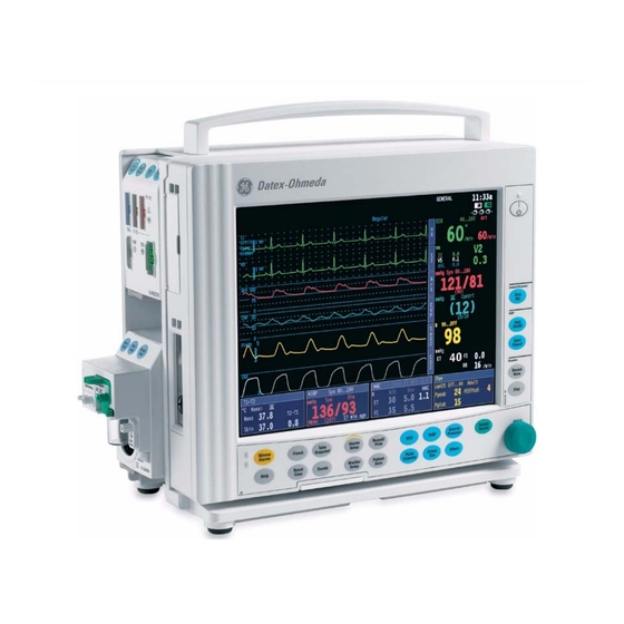
GE Healthcare
Datex-Ohmeda S/5
Datex-Ohmeda S/5
Technical Reference Manual
Conformity according to the Council Directive 93/42/EEC concerning Medical Devices
CAUTION: U.S. Federal law restricts this device to sale by or on the order of a licensed medical practitioner.
Outside the USA, check local laws for any restriction that may apply.
All specifications subject to change without notice.
Order code M1065281
st
1
edition
June 2, 2008
GE Healthcare Finland Oy
Helsinki, Finland
P.O. Box 900
FI-00031 GE, FINLAND
Tel: +358 10 39411
Fax: +358 9 1463310
www.gehealthcare.com
Copyright © 2008 General Electric Company. All rights reserved.
TM
Compact Anesthesia Monitor
TM
Compact Critical Care Monitor
Datex-Ohmeda Inc.
P.O. Box 7550
Madison, WI 53707-7550, USA
Tel: +1 608 221 1551
Fax: +1 608 222 9147
Advertisement
Chapters
Table of Contents
Troubleshooting

Related Manuals for GE Datex-Ohmeda S/5 Series


Summary of Contents for GE Datex-Ohmeda S/5 Series
- Page 1 Outside the USA, check local laws for any restriction that may apply. All specifications subject to change without notice. Order code M1065281 edition June 2, 2008 GE Healthcare Finland Oy Datex-Ohmeda Inc. Helsinki, Finland P.O. Box 7550 P.O. Box 900...
- Page 2 Responsibility of the manufacturer GE Healthcare Finland Oy (GE) is responsible for the effects on safety, reliability and performance of the equipment only if: •...
- Page 3 Product availability Some of the products mentioned in this manual may not be available in all countries. Please, consult your local representative for the availability.
- Page 5 Master Table of Contents Datex-Ohmeda Compact Anesthesia Monitor Compact Critical Care Monitor Technical Reference Manual, Order code: M1065281 edition Part I, General Service Guide Document No. Updated Description M1144951 -004 Introduction, System description, Installation, Interfacing, Functional check, General troubleshooting M1144953 -001 Planned Maintenance Instructions Part II, Product Service Guide Document No.
- Page 6 Datex-Ohmeda S/5 Compact Anesthesia and Compact Critical Care Monitors For your notes: Document no M1144951-004...
-
Page 7: Table Of Contents
Table of contents Table of contents Table of contents Table of figures About this manual Introduction Symbols ................5 1.1.1 Symbols on transport packaging. - Page 8 Datex-Ohmeda S/5 Compact Anesthesia and Compact Critical Care Monitors S/5 Compact Airway Modules, E-xxxx / M-xxxxx ........30 3.7.1 Sample gas exhaust .
- Page 9 Table of contents 5.3.6 Compact Airway Module, E-CXXXXX/ M-CXXXXX ....... . 59 5.3.7 Single width Airway Module, E-miniC/ M-miniC .
-
Page 10: Table Of Figures
Datex-Ohmeda S/5 Compact Anesthesia and Compact Critical Care Monitors Table of figures Figure 1 S/5 Compact Anesthesia Monitor system ........................3 Figure 2 General bus structure of S/5 system ..........................15 Figure 3 Principle of UPI section operation ............................16 Figure 4 General structure of parameter modules with patient isolation.................17 Figure 5 External connections of Compact Monitor frame F-CM(C)1 rev.05 ..............20... -
Page 11: About This Manual
Installation and service are allowed by authorized service personnel only. GE Healthcare Finland Oy (GE) assumes no responsibility for the use or reliability of its software in equipment that is not furnished by GE. - Page 12 Datex-Ohmeda S/5 Compact Anesthesia and Compact Critical Care Monitors S/5 Compact Critical Care Monitor For instructions for daily use including cleaning and daily maintenance, clinical aspects and basic methods of measurement: S/5 Compact Critical Care Monitors, User’s Guide S/5 Compact Critical Care Monitors, User’s Reference Manual For more information about the iCentral, S/5 Arrhythmia Workstation and anesthesia record keeping solution, see the “Technical Reference Manuals”...
-
Page 13: Introduction
Introduction Introduction The modular design makes the system flexible and easy to upgrade. In addition to patient parameter modularity and easy upgrades, the monitor can be upgraded to anesthesia record keeping, wired and wireless networking and memory card operation. Additionally, external devices can be interfaced to the monitor with interface modules. - Page 14 Datex-Ohmeda S/5 Compact Anesthesia and Compact Critical Care Monitors Communication between monitors You can use the Compact Monitor as a stand-alone monitor or for: − viewing and receiving data (alarms, vital signs) from other patient monitors − gathering and storing data during transportation. To view other patient monitors, the monitor needs to be connected to the network (LAN or WLAN).
-
Page 15: Symbols
Introduction 1.1 Symbols 1.1.1 Symbols on transport packaging The contents of the transport package are fragile and must be handled with care. Indicates the correct upright position of the transport package. The transport package must be kept in a dry environment. Indicates the temperature limitations within which the transport package should be stored. -
Page 16: Equipment Safety Symbols
Datex-Ohmeda S/5 Compact Anesthesia and Compact Critical Care Monitors 1.1.3 Equipment safety symbols Attention, consult accompanying documents. When displayed next to the O value, indicates that the FiO low alarm limit is set below 21%. When displayed next to the HR value, indicates that the pacer is set on R. On the modules or frames indicates that modules with identical measurements should not be used in the same monitor. -
Page 17: Other Symbols
Introduction Type BF (IEC 60601-1) protection against electric shock. Type BF (IEC 60601-1) defibrillator-proof protection against electric shock. Type CF (IEC 60601-1) protection against electric shock. Type CF (IEC 60601-1) defibrillator-proof protection against electric shock. When displayed in the upper left corner of the screen, indicates that the alarms are silenced. - Page 18 Datex-Ohmeda S/5 Compact Anesthesia and Compact Critical Care Monitors The monitor is connected to the Datex-Ohmeda Network (LAN). The monitor is connected to the Datex-Ohmeda Network (WLAN). Data Card (green) and/or Menu Card (white) is inserted. WLAN signal strength. The number of segments corresponds to the signal strength: four segments indicate strong signal, one segment weak signal.
- Page 19 Introduction IPX class: Degree of protection against harmful ingress of water as detailed in the IEC 60529: IPX0 - Ordinary equipment IPX1 - Protection against vertically falling water drops. IPX2 - Protection against vertically falling water drops when enclosure tilted IPX3 up to 15 °.
-
Page 20: Safety
Datex-Ohmeda S/5 Compact Anesthesia and Compact Critical Care Monitors 1.2 Safety The following list contains general warnings and cautions you should know before installing, maintaining or servicing the system. Warnings and cautions specific to the use of the system can be found in the User’s Guide and User’s Reference Manual. 1.2.1 Safety precautions Warnings WARNING... - Page 21 Introduction • A printer or computer must be supplied from an additional transformer providing at least basic isolation (isolating or separating transformer). • If you accidentally drop the monitor, modules or frames, have them checked by authorized service personnel prior to clinical use. •...
- Page 22 • Use only accessories, including mounts and batteries, and defibrillator-proof cables and invasive pressure transducers approved by GE Healthcare. For a list of approved supplies and accessories, see the “Supplies and Accessories” catalog delivered with the monitor. Other cables, batteries, transducers and accessories may cause a safety hazard, damage the equipment or the system, result in increased emissions or decreased immunity of the equipment or system or interfere with the measurement.
-
Page 23: Esd Precautionary Procedures
Special components • Special components are used in these monitors that are vital to assure reliability and safety. GE Healthcare assumes no responsibility for damage, if replacement components not approved by GE Healthcare are used. • A lithium battery on the CPU Board. Dispose of the faulty IC containing the battery according to local regulations. -
Page 24: Disposal
Datex-Ohmeda S/5 Compact Anesthesia and Compact Critical Care Monitors to prevent build-up of electrostatic charge and how and why to discharge one’s body to earth or to the frame of the equipment or bond oneself by means of a wrist strap to the equipment or the earth prior to making a connection. -
Page 25: System Description
System description System description 2.1 Introduction Datex-Ohmeda monitors build up a freely configurable modular system. The architecture is designed to enable different module combinations so that the user is able to get the desirable parameter and feature set. This modular approach makes it possible to add new features when they are needed. -
Page 26: Distributed Processing
Datex-Ohmeda S/5 Compact Anesthesia and Compact Critical Care Monitors 2.3 Distributed processing A system assembled from Datex-Ohmeda products is a multiprocessor system. All parameter modules have their own microprocessor, which performs functions such as module key control, waveform filtering, parameter related computing and pneumatic control, etc. At the same time the main CPU performs higher level tasks such as trending and alarm control. -
Page 27: Software Loading
System description 2.5 Software loading The program memory on the CPU board is loaded with monitor software at the factory. The software is used for running all the functions that are integrated into the PC board. For service and upgrade procedures, the CPU board is fitted with a PCMCIA card drive through which new software can be loaded. - Page 28 Datex-Ohmeda S/5 Compact Anesthesia and Compact Critical Care Monitors For your notes: Document no M1144951-004...
-
Page 29: System Installation
Confirm that all components are undamaged. If any of the components are damaged, contact the shipper. Confirm that all components are included. If any of the components are missing, contact your GE Healthcare distributor. 3.2 Choosing location Consider the following aspects: •... -
Page 30: Compact Monitor Connections
Datex-Ohmeda S/5 Compact Anesthesia and Compact Critical Care Monitors 3.3.1 Compact Monitor connections Figure 5 External connections of Compact Monitor frame F-CM(C)1 rev.05 Air filter NET connector NET ID connector (not used with N-CMW) Recorder (optional) SYNC connector Connector for external keyboard (anesthesia record keeping solution keyboard), K-CREMCO or Barcode Reader Potential equalization Serial port... -
Page 31: Connecting To Mains
System installation Figure 6 External connections of Compact Monitor frame F-CM(C)1 rev.00...03 Dust filters Recorder unit (optional) Connector for factory use only Synchronization connector Connector for external keyboard (anesthesia record keeping solution keyboard), K-CREMCO or Barcode Reader Potential equalization connector Serial port connector Receptacle for power cord NET ID connector... -
Page 32: Connecting To Network
Datex-Ohmeda S/5 Compact Anesthesia and Compact Critical Care Monitors disappears, or in STBY mode the Stby LED stops blinking (may take up to 10 hours if the batteries are fully discharged). WARNING The power cord may only be connected to a three-wire, grounded, hospital grade receptacle. -
Page 33: Inserting The Parameter Modules
System installation 3.3.5 Inserting the parameter modules Insert each plug-in parameter module into a module slot. Firmly press the module in position. NOTE: Ensure that the module is properly oriented (i.e. the module release latch is facing downward). Do not use two or more modules with identical functions in the monitor. Modules with identical functions are: •... -
Page 34: Figure 7 E-Psm(P) Mounting Accessories
Datex-Ohmeda S/5 Compact Anesthesia and Compact Critical Care Monitors Figure 7 E-PSM(P) mounting accessories M1054424 Interface Module for PSM, E-INTPSM M1051021 Frame Mount for PSM M1049197 Pole Mount for PSM, short M1051023 Pole Mount for PSM, long Frame Mount for PSM – Instructions connecting to the Compact Monitor frame 1. -
Page 35: Downloading Monitor Software
System installation WARNING Make sure that the Pole Mount for PSM is always used in vertical position to prevent water from entering the E-PSM(P) module. Pole Mount for PSM – Instructions for connecting to an IV pole, vertical position Fasten the Pole Mount for PSM with the fastening screw of the clamp and tighten properly to an IV pole. -
Page 36: Performing Factory Reset
Datex-Ohmeda S/5 Compact Anesthesia and Compact Critical Care Monitors Wait for approximately 80 seconds. After the start-up screen appears, enter the Service View and make sure that the information regarding monitor software has been updated. Memorize the serial number of new software. Remove the software card. -
Page 37: Installing The Datex-Ohmeda Network Upgrade, U-Cmnet
System installation Detach the cover plate on the network connectors at the rear of the frame unit (above the power supply unit). Leave the collar on the connectors attached. Open the cover for card drive slots (on the left side of the monitor). Insert the option software card into one of the card drive slots and press the software card firmly in position. -
Page 38: Installing The S/5 Recorder Upgrade, U-Cmrec1
Datex-Ohmeda S/5 Compact Anesthesia and Compact Critical Care Monitors option software, the serial number of the monitor is written on the software card, and if the downloading for some reason would fail, the software can be downloaded again onto the same monitor, but not onto any other monitor. -
Page 39: S/5 Remote Controller, K-Cremco
System installation Attach the recorder to the side panel with two screws at the back of the recorder (the screws can be accessed inside the recorder). Check that the recorder and the side panel are aligned and the recorder tightly attached. Figure 8 Installation of the U-CMREC1 Attach the device plate to the back cover of the monitor, near the other device plates. -
Page 40: S/5 Compact Airway Modules, E-Xxxx / M-Xxxxx
Datex-Ohmeda S/5 Compact Anesthesia and Compact Critical Care Monitors Figure 9 ARK Barcode Reader, N-SCAN connected to Compact Monitor 3.7 S/5 Compact Airway Modules, E-xxxx / M-xxxxx This chapter provides information for installing Compact Airway Modules E-xxxxx. Figure 10 Compact Airway Module, E-XXXX Connection to frame Ensure that the module is properly orientated (i.e. -
Page 41: Sample Gas Exhaust
System installation Align the module insertion guide slot with the insertion guide. Push the module into the frame until it clicks. 3.7.1 Sample gas exhaust Preventing operation room pollution When N O or volatile anesthetics are used, pollution of the operation room by these gases should be prevented. -
Page 42: Figure 12 Connecting The Gas Module To The Scavenging Connector Of S/5 Avance
Delivery Unit (ADU), you need an optional adapter connected to the patient breathing tubes. Take special care when returning sample gas to the patient circuit. For further information, please contact your GE Healthcare distributor. NOTE: If E-miniC is being used, do not return the sample gas to the patient circuit. -
Page 43: Troubleshooting
System installation SCAVENGING SAMPLE GAS OUT Figure 13 Sample gas returned to patient circuit in ADU 3.7.2 Troubleshooting If a problem occurs during a functional examination, check the components of the monitor according to the following troubleshooting chart. If the problem persists, please refer to Part II of this Technical Reference Manual. - Page 44 Datex-Ohmeda S/5 Compact Anesthesia and Compact Critical Care Monitors For your notes: Document no M1144951-004...
-
Page 45: Interfacing
Interfacing Interfacing External devices can be interfaced with the S/5 Compact Anesthesia and S/5 Compact Critical Care Monitors via the Compact Monitor’s serial port, via the Interface Module, E-INT / M-INT, and via the Device Interfacing Solution, N-DISxxx. The serial port can be used for interface with: •... -
Page 46: Connection To External Datex-Ohmeda Monitors
Datex-Ohmeda S/5 Compact Anesthesia and Compact Critical Care Monitors Table 4 Transference of parameters, Datex-Ohmeda monitors Device Waveforms Numerics Alarms (analog) Cardiocap E-INT / M-INT -> CO Et&Fi Airway gases, None Respiration rate, , Pulse rate Capnomac E-INT / M-INT -> CO Et&Fi Airway gases, None Capnomac II... -
Page 47: Connection To Critikon Dinamap 1846Sx, Abbott Oximetrix 3 And Baxter Explorer
Interfacing Connect the 25 pin D-connector to the corresponding connector on the other monitor. Tighten the finger screws. 4.1.2 Connection to Critikon Dinamap 1846SX, Abbott Oximetrix 3 and Baxter Explorer Use the INT-External Device Cable. Make sure that the power to both monitors is turned off. Connect the 9 pin D-connector to one of the connectors on the Interface Module, E-INT / M-INT. -
Page 48: Interfacing External Bedside Devices Via Device Interfacing Solutions, N-Disxxx
Trademark of Dräger Medical AG & Co Trademark of Nellcor Puritan Bennet Inc Trademark of Maquet Critical Care AB part of the Getinge Group (previously trademark of Siemens) Trademark of GE Healthcare Finland Oy Replaced by N-DISVENT Device Monitors N-DISOXIM3... -
Page 49: Device Interfacing Solution Components
Trademark of Hospira Inc. (previously trademark of Abbott Laboratories) Trademark of Aspect Medical Systems Trademark of Edwards Lifesciences Corporation Trademark of Pulsion Medical Systems Trademark of GE Healthcare Finland Oy Device Blood gas analyzers N-DISOPT AVL Opti CCA Device Heart-lung machines... -
Page 50: Mounting
Datex-Ohmeda S/5 Compact Anesthesia and Compact Critical Care Monitors label specifying the external device LED indicators black bus cable from another interfacing module, if needed grey device specific cable to the communication port of the external device black bus cable to the monitor’s DIS connector (or to another interfacing module) Figure 14... -
Page 51: Selecting The External Device
Interfacing Figure 15 An example of interfacing external devices with Device Interfacing Solution Datex-Ohmeda S/5 Compact Anesthesia Monitor (with software L-CANE02(A) or later) Aestiva/5 anesthesia machine RGM monitor Interfacing module NOTE: You can connect up to ten (10) interfacing modules to one system simultaneously. Check the maximum number of modules: one meter cable = max. -
Page 52: Functional Check
Datex-Ohmeda S/5 Compact Anesthesia and Compact Critical Care Monitors 4.2.5 Functional check There are two ways to check the function of the Device Interfacing Solution: Monitor Setup Press the key. Select Interfacing and open the Status Page menu. The status page shows you the current communication status of the interfacing module (1 - 10). -
Page 53: Interfacing Datex-Ohmeda Anesthesia Delivery Unit
Interfacing 4.3 Interfacing Datex-Ohmeda Anesthesia Delivery Unit It is possible to interface the Datex-Ohmeda Anesthesia Delivery Unit to the S/5 Compact Anesthesia Monitor via the serial interface port. The data link is bi-directional. The parameters transferred to the Anesthesia Delivery Unit are summarized in Table 7 and the events transferred to the S/5 Compact Anesthesia Monitor are summarized in... -
Page 54: Interfacing Dräger Cicero, Cato, Julian And Narkomed 2C (By Nad)
Datex-Ohmeda S/5 Compact Anesthesia and Compact Critical Care Monitors Table 8 Events transferred from S/5 Anesthesia Delivery Unit to the S/5 Compact Anesthesia Monitor Events transferred once a minute Ventilator settings Ventilation (mode) Tidal Volume Minute Volume Resp. Rate I:E Times: inp I:E Times: exp InspPause Ventilator measurements... -
Page 55: Setting Communication Parameters
Interfacing Make sure that the power to both monitors is turned off. Connect the 9 pin D-connector to one of the connectors on the Interface Module, E-INT / M-INT. Tighten the finger screws. Connect the 25 pin D-connector to a corresponding connector on the anesthesia machine. - Page 56 Datex-Ohmeda S/5 Compact Anesthesia and Compact Critical Care Monitors Table 10 Parameters transferred from Dräger Cato, Julian and Narkomed 2C (NAD) monitor to the S/5 Compact Anesthesia Monitor or S/5 Compact Critical Care Monitor Selection Waveforms Numerics States Gases / SSS (kPa, mmHg, %) Fi &...
-
Page 57: Interfacing Printer
4.5.2 Connection to serial printers A serial printer is connected to the serial port connector X11 on the frame unit. Contact your authorized GE Healthcare distributor for advice on suitable serial printers. 4.5.3 Connection to parallel printers A parallel printer is connected to the serial interface port connector X11 on the frame unit via the Serial-to-Parallel Converter, order code 78030, model PI130-R2 or PI1115A. -
Page 58: Figure 16 Connecting S/5 Compact Monitor To Printer, Converter Model Pi130-R2
Datex-Ohmeda S/5 Compact Anesthesia and Compact Critical Care Monitors Check the DIP-switch settings on the converter (order code 78030, model PI130-R2): Position Flow Control: hardware LED: Enabled Parity/D, Bits/S, Bit: None/8/1 D.Rate (kbps): 115,2 Connect a DB25 female-to-female gender changer (order code 78032) between the printer cable and converter. -
Page 59: Connection To Printer
4.6 Interfacing computer A computer is connected to the serial port connector X11 on the frame unit. Contact your authorized GE Healthcare distributor for further advice on computer interface. WARNING Always make sure that the combination complies with the international safety standard IEC 60601-1-1 for medical electrical systems and with the requirements of local authorities. -
Page 60: Digital Outputs
Datex-Ohmeda S/5 Compact Anesthesia and Compact Critical Care Monitors Table 11 Coding element connector, X4 9 pin female D-connector Signal IDCS1 (chip select) IDCL (clock) IDDI (data in) IDDO (data out) IDPE (protect enable) +5Vdc Direct ECG Nurse call Table 12 Synchronization connector, X8 4 pin female connector Signal... -
Page 61: S/5 Pressure Temp Module, E-Pt Or M-Pt, Output Signals
E-PSM / E-PSMP. The ECG signal from the modules is channel 1 (ECG1). The channels 2 and 3 (ECG2, ECG3) are not transmitted. Make sure that the signal in channel 1 (ECG1) is good enough (extensive QRS for IABP synchronization). For further information, please contact your authorized GE Healthcare distributor. Pressure out (X8 pin 4) −... - Page 62 Datex-Ohmeda S/5 Compact Anesthesia and Compact Critical Care Monitors For your notes: Document no M1144951-004...
-
Page 63: Functional Check
Functional check Functional check These instructions include procedures for a functional check for Datex-Ohmeda S/5 Compact Anesthesia Monitor and S/5 Compact Critical Care Monitor. The functional check is recommended to be performed after monitor installation. These instructions include a “Functional check form, Datex-Ohmeda S/5 CAM, CCCM” to be filled in when performing the procedures. - Page 64 Datex-Ohmeda S/5 Compact Anesthesia and Compact Critical Care Monitors For product(s) Tool Order No. Multi-Link ECG accessories, IEC E-PSM(P)/ E-PRESTN/ M-PRESTN Multi-link 3-leadwire set 412682-003 Multi-link 5-leadwire set 412681-003 Multi-link 5-leadwire set, C2-C6 416467-004 E-PRESTN/ M-PRESTN w/ (E12) Multi-link 12-lead ECG trunk 416035-002 cable Multi-Link ECG accessories, AHA...
-
Page 65: Hemodynamic Patient Simulators
Functional check For product(s) Tool Order No. Tonometry Module, E-TONO/ Calibration gas and regulator 755580/755534* M-TONO Sampling line 733251 TONO-14F or another suitable Tonometrics catheter TONO-_F catheter Luer plug Pressure manometer BIS Module, E-BIS/ M-BIS BIS simulator or 900509 BIS Sensor simulator 900508 E-ENTROPY/ M-ENTROPY Entropy simulator... -
Page 66: Visual Inspection
Datex-Ohmeda S/5 Compact Anesthesia and Compact Critical Care Monitors Patient simulator Module Parameter M1010831 MedSim 874027 M-PRESTN Multilink ECG acc. Not compatible M1010832 M1010832 Auto Start Zero Zero On/Off Cancel NIBP InvBP Not compatible M-NESTPR Not compatible 300 series acc. 12 lead ECG Not compatible 300 series acc. -
Page 67: Functional Inspection
Functional check CAUTION Ensure that the module is properly orientated (i.e. module release latch facing downward) before insertion. 5.3 Functional inspection WARNING Handle the water trap and its contents as you would any body fluid. Infectous hazard may be present. 5.3.1 General Connect the mains power cord. -
Page 68: Display
Datex-Ohmeda S/5 Compact Anesthesia and Compact Critical Care Monitors Others -Resp Setup -Size -1.0 - Resp Rate Source – AUTO - Measurement – ON - Detection Limit – AUTO 5.3.2 Display Check that the picture on the screen is correct. 5.3.3 Keyboard(s) Tests with all the connected keyboards: −... - Page 69 Functional check 5.3.6 Compact Airway Module, E-CXXXXX/ M-CXXXXX Wait until the message ‘Calibrating gas sensor’ disappears from the screen. Check that the fan is running. If the module contains membrane keys on the front panel, press each of the keys for at least one second and check that they are identified.
- Page 70 Datex-Ohmeda S/5 Compact Anesthesia and Compact Critical Care Monitors Connect an ECG cable to the module. Connect the cable leads to a patient simulator. Check that all ECG and impedance respiration information is shown on the monitor screen as configured on the simulator. Turn the simulator off.
- Page 71 Functional check Temperature measurement Check the temperature channels with a patient simulator. Check that the temperature measurement information is shown on the monitor screen as configured on the simulator. 5.3.11 Dual pressure Module, E-PP/ M-PP Zero P5 Zero P6 Check the function of the front panel keys.
- Page 72 Datex-Ohmeda S/5 Compact Anesthesia and Compact Critical Care Monitors Attach the SpO2 probe on your finger. Check that a reading of 95-100 and a proper SpO2 waveform appear. 5.3.15 Datex-Ohmeda Oxygen Saturation module, M-OSAT Connect an OxyTip ® + Reusable Finger Sensor such as Integrated Finger Sensor OXY-F4-N to the module.
- Page 73 Functional check Check that the quality of the recordings is acceptable. 5.3.20 Network connection Check that the Mon-Net cable connector and the Identification plug are clean and intact, then connect them to the frame unit. Check that the monitor connects to the network, i.e. the network symbol appears on the upper right-hand corner of the screen.
- Page 74 Datex-Ohmeda S/5 Compact Anesthesia and Compact Critical Care Monitors 5.3.25 General • Switch the monitor to standby • Perform final cleaning • Fill in all necessary documents Document no M1144951-004...
-
Page 75: Figure 18 S/5 Compact Monitor General Troubleshooting Flowchart
General troubleshooting General troubleshooting Monitor not functioning Power cord connected? Connect power cord Monitor can be Batteries were started now? empty Possible AC/DC On/Standby LED unit failure. Monitor can be is ON or blinks? Replace AC/DC started now? unit. Frame Unit fan is Display Unit AC/DC Unit running? -
Page 76: Figure 19 Software Troubleshooting
Datex-Ohmeda S/5 Compact Anesthesia and Compact Critical Care Monitors 6.1 Software troubleshooting chart SERVICE PROCEDURE: Downloading of Service software or Upgrade software from a software card onto the CPU board. Insert the software card into the card slot. Check the software Turn the power ON. - Page 77 Appendix A, Functional check form, Datex-Ohmeda S/5 CAM, CCCM APPENDIX A: Functional check form, Datex-Ohmeda S/5 CAM, CCCM Customer Service Service engineer Date Monitor Installation Frame: F-CM________ System options: E/M- Software: E/M- E/M- E/M- Measuring equipment / test gases used: Equipment / tool / gas: Manufacturer: Model/Type/Part...
- Page 78 Datex-Ohmeda S/5 Compact Anesthesia and Compact Critical Care Monitors Functional Inspection N.A. Fail 5.3.6. Compact Airway Module, E-CXXXXX/ M-CXXXXX . Compact Airway Modules with the Patient Spirometry option . For all Compact Airway Modules 5.3.7. Single width Airway Module, E-miniC/ M-miniC Notes 5.3.8.
- Page 79 Appendix A, Functional check form, Datex-Ohmeda S/5 CAM, CCCM Functional Inspection N.A. Fail 5.3.13. NIBP module, M-NIBP 5.3.14. Nellcor Compatible Saturation module, E-NSATX/ E-NSAT/ M-NSAT 5.3.15. Datex-Ohmeda Oxygen Saturation module, M-OSAT 5.3.16. BIS Module, E-BIS/ M-BIS 5.3.17. Entropy Module, E-ENTROPY/ M-ENTROPY 5.3.18.
- Page 80 Datex-Ohmeda S/5 Compact Anesthesia and Compact Critical Care Monitors For your notes: -4(4) Document no M1144951-004...
- Page 81 Appendix B, ElectroMagnetic Compatibility APPENDIX B: ElectroMagnetic Compatibility Table 1 Guidance and manufacturer’s declaration – electromagnetic emissions Guidance and manufacturer’s declaration – electromagnetic emissions The S/5™ CAM/ CCCM is intended for use in the electromagnetic environment specified below. The customer or the user of the S/5™ CAM/ CCCM should assure that it is used in such an environment. Emissions test Compliance Electromagnetic environment - guidance...
- Page 82 Datex-Ohmeda S/5 Compact Anesthesia and Compact Critical Care Monitors Table 2 Guidance and manufacturer’s declaration – electromagnetic immunity Guidance and manufacturer’s declaration – electromagnetic immunity The S/5™ CAM/ CCCM is intended for use in the electromagnetic environment specified below. The customer or the user of the S/5™...
- Page 83 Appendix B, ElectroMagnetic Compatibility Table 3 Guidance and manufacturer’s declaration – electromagnetic immunity Guidance and manufacturer’s declaration – electromagnetic immunity The S/5™ CAM/ CCCM is intended for use in the electromagnetic environment specified below. The customer or the user of the S/5™ CAM/ CCCM should assure that it is used in such an environment. Immunity test IEC 60601 test level Compliance...
- Page 84 Datex-Ohmeda S/5 Compact Anesthesia and Compact Critical Care Monitors NOTE 1 At 80 MHz and 800 MHz, the higher frequency range applies. NOTE 2 These guidelines may not apply in all situations. Electromagnetic propagation is affected by absorption and reflection from structures, objects and people. Field strengths from fixed transmitters, such as base stations for radio (cellular/cordless) telephones and land mobile radios, amateur radio, AM and FM radio broadcast and TV broadcast cannot be predicted theoretically with accuracy.
- Page 85 Appendix B, ElectroMagnetic Compatibility Table 4 Recommended separation distances between portable and mobile RF communications equipment and the S/5™ CAM/ CCCM Recommended separation distances between portable and mobile RF communications equipment and the S/5™ CAM/ CCCM. The S/5™ CAM/ CCCM is intended for use in an electromagnetic environment in which radiated RF disturbances are controlled.
- Page 86 Datex-Ohmeda S/5 Compact Anesthesia and Compact Critical Care Monitors For your notes: -6(6) Document no M1144951-004...
- Page 87 Appendix C, Channel Mask Selections APPENDIX C: Channel Mask Selections Country Selection Allowed Band DS Channels Argentina 07FF 2.400 - 2.4835 01 - 11 Australia 1FFF 2.400 - 2.4835 01 - 13 Austria 1FFF 2.400 - 2.4835 01 - 13 Belgium 1FFF 2.400 - 2.4835...
- Page 88 Datex-Ohmeda S/5 Compact Anesthesia and Compact Critical Care Monitors Country Selection Allowed Band DS Channels Sweden 1FFF 2.400 - 2.4835 01 - 13 Switzerland 1FFF 2.400 - 2.4835 01 - 13 Taiwan 1FFF 2.400 - 2.4835 01 - 13 Thailand 1FFF 2.400 - 2.4835 01 - 13...
- Page 89 CAUTION: U.S. Federal law restricts this device to sale by or on the order of a licensed medical practitioner. Outside the USA, check local laws for any restriction that may apply. All specifications subject to change without notice. Document number M1144953-001 April 9, 2008 GE Healthcare Finland Oy Datex-Ohmeda Inc. Helsinki, Finland P.O. Box 7550 P.O. Box 900...
- Page 91 Table of contents Table of contents Table of contents Planned maintenance instructions Introduction ................1 Recommended tools .
- Page 92 Datex-Ohmeda S/5 Compact Anesthesia and Compact Critical Care Monitors 2.2.18Nellcor Compatible Saturation module, E-NSATX, E-NSAT, M-NSAT ....22 2.2.19Datex-Ohmeda Oxygen Saturation module, M-OSAT......23 2.2.20Memory .
-
Page 93: Planned Maintenance Instructions
Planned maintenance instructions 1.1 Introduction These instructions include procedures for planned maintenance (PM) for the Datex-Ohmeda S/5 Compact Anesthesia Monitor and S/5 Compact Critical Care Monitor. The Planned maintenance should be performed once a year. These instructions include “Planned maintenance check form, S/5 Compact Monitors” to be filled in when performing the corresponding procedures. -
Page 94: Recommended Tools
Datex-Ohmeda S/5 Compact Anesthesia and Compact Critical Care Monitors 1.2 Recommended tools NOTE: Use only properly maintained, calibrated and traceable measurement equipment for the specified calibrations and adjustments to ensure accuracy. For product(s) Tool Order No. All Airway modules Flowmeter Compact Airway Module, E-CAiO(VX)/ Calibration gas and regulator 755583/755534*... - Page 95 For product(s) Tool Order No. E-PSM(P) / E-PRESTN finger probe OXY-F-UN Interconnect Cable OXY-ES3 M-PRESTN finger probe OXY-F4-N or SAS-F4 E-NSATX 40xxxxx-001 Nellcor OxiMax Spo2 interconnect cable E-NSAT/ M-NSAT Nellcor SpO finger probe with DOC-10 cable M-OSAT OxyTip® + Integrated Finger Sensor OXY-F4-N Hemodynamic modules w/ (T) Temperature test set 884515...
-
Page 96: Hemodynamic Patient Simulators
Datex-Ohmeda S/5 Compact Anesthesia and Compact Critical Care Monitors 1.2.1 Hemodynamic patient simulators The following tables present the patient simulators’ compatibility with each hemodynamic module, and the accessories needed: Table 1 Patient simulators’ compatibility with each hemodynamic module Patient simulator Module Parameter M1010831... -
Page 97: Recommended Parts
Patient simulator Medsim Inv.BP adapter cable M1010858 Lionheart & MPS450 Temperature adapter cable M1010846 Lionheart & MPS450 Inv.BP adapter cable M1010862 1.3 Recommended parts For product(s) Part Order No. CM(C) Frame Unit Fan filter 896085 CM(C) Display Unit Fan filter 874594 Central Processing Board Battery for SRAM/Timekeeper... -
Page 98: Pm Parts For Compact Airway Modules, E-Cxx/ M-Cxx Without Co2 Absorber - Critical Care
Datex-Ohmeda S/5 Compact Anesthesia and Compact Critical Care Monitors 1.4.2 PM parts for Compact Airway Modules, E-CXX/ M-CXX without CO2 absorber - Critical Care Part Order No. For product(s) Special tube (Nafion) 733382 All Airway modules Ref. gas sticker 893110 Compact Airway Modules Filter (2 pcs) 886136... -
Page 99: Pm Parts For Airway Module, E-Minic/ M-Minic
1.4.4 PM parts for Compact Airway Modules, E-CXX/ M-CXX with CO2 absorber - Critical Care Part Order No. For product(s) Special tube (Nafion 2 pcs) 733382 All Airway modules Ref. gas sticker 893110 Compact Airway Modules Filter (2 pcs) 886136 Compact Airway Modules Filter assembly 896025... - Page 100 Datex-Ohmeda S/5 Compact Anesthesia and Compact Critical Care Monitors For your notes: Document no M1144953-001...
-
Page 101: Planned Maintenance Check List
Planned maintenance check list 2.1 Visual inspection/preparation 2.1.1 General NOTE: Wear a static control wrist strap when handling PC boards. Electrostatic discharge may damage components on the board. Make sure that the monitor is switched to standby. Disconnect the mains power cord. If the monitor is connected to the Datex-Ohmeda Network, disconnect the Mon-Net cable from the monitor. -
Page 102: Single-Width Airway Module, E-Minic/ M-Minic
Datex-Ohmeda S/5 Compact Anesthesia and Compact Critical Care Monitors − Replace the Ref. filter assembly. − Replace the filters in the pneumatic unit (1 or 2 pcs). − Check the D-fend O-rings and replace them, if necessary. − Replace the D-fend and sampling line. −... -
Page 103: Recorder Unit
2.1.5 Recorder Unit Clean the recorder. − Open the paper compartment hatch and remove the paper roll, if installed. − Remove any paper chaff from the paper compartment. − Clean the thermal printhead and the small glass window in front of the static brush with a cotton swab dipped in isopropyl alcohol, if necessary. - Page 104 Datex-Ohmeda S/5 Compact Anesthesia and Compact Critical Care Monitors - Stim. Intensity - 90 dB - Sweep length - 100 ms - EP size - 1 Recorder - Record Waveforms - Waveform 1 - ECG1 - Waveform 2 - P1 - Waveform 3 - P2 Invasive Pressures - P1 ‘ART’...
-
Page 105: Display
2.2.2 Display Check that the picture on the screen is adjusted correctly.. 2.2.3 Keyboard(s) Tests with the Command Board: − Help Press the key. Turn the ComWheel in both directions and check that the cursor in the menu moves correspondingly. Select Normal Screen and check that the menu disappears from the screen. - Page 106 Datex-Ohmeda S/5 Compact Anesthesia and Compact Critical Care Monitors Check that the module configuration displayed corresponds with the Compact Airway Module type being used. Check that the Time-outs, Bad checksums and Bad c-s by mod values are not increasing faster than by 5 per second. Enter the Gases service menu: Check that the ‘Ambient’...
-
Page 107: Single-Width Airway Module, E-Minic/ M-Minic
Insert the Compact Airway Module into the frame. Switch the monitor back on and wait until the message ‘Calibrating gas sensor’ disappears from the screen. 13. Block the tip of the sampling line with your finger and check that the message ‘Sample line blocked’... -
Page 108: Multiparameter Hemodynamic Modules
Datex-Ohmeda S/5 Compact Anesthesia and Compact Critical Care Monitors Start-Stop Connect the catheter to the module. Start measurement by pressing the on the module. Check that the catheter fills up. Start-Stop Stop the measurement by pressing the key. Check that Meas. Off text appears in the digit field. - Page 109 Change baseline impedance on the simulator and check that appropriate RESP waveform and RR values are shown again within 30 seconds. Turn the simulator off. Check that the ‘Asystole’ and ‘Apnea’ messages are displayed. Temperature measurement Enter the ESTP: STP service menu. Check that the Time-outs, Bad checksums and Bad c-s by mod values are not increasing faster than by 5 per second.
- Page 110 Datex-Ohmeda S/5 Compact Anesthesia and Compact Critical Care Monitors 21. Attach an adult NIBP hose and cuff onto your arm and perform one NIBP measurement. Check that the module identifies the cuff, i.e. the text ‘Adult’ appears in the NIBP digit field for a short time.
- Page 111 Check that the Mod Mon Time-outs, Mon Mod Bad checksums, Mod Mon Bad Checksums and Bad Checksums from BIS values in the module view are not increasing faster than by 5 per second. Check that the memories of the module have passed the internal memory test, i.e. RAM, ROM and EEPROM all state OK.
- Page 112 Datex-Ohmeda S/5 Compact Anesthesia and Compact Critical Care Monitors 2.2.13 Pressure/Pressure Temp Modules, E-P, E-PT, M-P, M-PT Enter the P/PT module service menu: Check that the Time-outs, Bad checksums and Bad c-s by mod values are not increasing faster than by 5 per second. Check that the PT board memories have passed the internal memory test, i.e.
- Page 113 Zero the InvBP channel. Then check that the values and waveforms correspond to the simulator settings. measurement Check that the SvO values Meas. state, OM fail and OM temp. in the COP module service menu all show NO OM. Checks with the SvO simulator: Turn the SvO simulator pulsation switch to Medium and the range switch to Normal...
- Page 114 Datex-Ohmeda S/5 Compact Anesthesia and Compact Critical Care Monitors Check the NIBP watchdog timer activation pressure with a pressure manometer. Check the NIBP watchdog timer by performing Watchdog – Test Adult and Test Infant. Check the safety valve by performing Safety Valve – Adult and Infant. Attach an adult NIBP cuff onto your arm and perform one NIBP measurement.
- Page 115 Connect a Nellcor SpO finger probe to the module. Check that the message ‘Pulse search’ is shown and the corresponding status information in the menu is active. Check that the shown message changes to ‘Check probe’ within 30 seconds. Attach the SpO probe on your finger.
- Page 116 Datex-Ohmeda S/5 Compact Anesthesia and Compact Critical Care Monitors 2.2.22 Network Option Check that the Mon-Net cable connector and the Identification plug are clean and intact, then connect them to the frame unit. Check that the monitor connects to the Datex-Ohmeda Network, i.e.
- Page 117 2.2.26 General Storing trend data Check that the monitor is capable of storing the trend information and temporary settings in a short (max. 15 minutes) standby situation with no power cord. Service reset Check the Service Reset switch. Switch the monitor to standby and press the Service Reset switch for at least five seconds.
- Page 118 Datex-Ohmeda S/5 Compact Anesthesia and Compact Critical Care Monitors For your notes: Document no M1144953-001...
- Page 119 Appendix Planned maintenance check form, S/5 Compact Monitors APPENDIX A: Planned maintenance check form, S/5 Compact Monitors Customer Service Service engineer Date Monitor Installation Frame: F-CM________ System options: E/M- Software: E/M- E/M- E/M- Measuring equipment / test gases used: Equipment / tool / gas: Manufacturer: Model/Type/Part Serial Number /...
- Page 120 Datex-Ohmeda S/5 Compact Anesthesia and Compact Critical Care Monitors Functional Inspection N.A. Fail 2.2.1. General 2.2.2. Display 2.2.3. Keyboard(s) 2.2.4. Display Unit 2.2.5. Frame Unit Notes 2.2.6. Compact Airway Module, E-CXXXXX/ M-CXXXXX . Anesthesia Agent . Patient Spirometry . General Notes 2.2.7.
- Page 121 Appendix Planned maintenance check form, S/5 Compact Monitors Functional Inspection N.A. Fail 2.2.10. EEG Module, E-EEG/ M-EEG and EEG Headbox, N-EEG 2.2.11. BIS Module, E-BIS/ M-BIS 2.2.12. Entropy Module, E-ENTROPY/ M-ENTROPY Notes 2.2.13. Pressure/Pressure Temp Modules, E-P, E-PT, M-P, M-PT .
- Page 122 Datex-Ohmeda S/5 Compact Anesthesia and Compact Critical Care Monitors Functional Inspection N.A. Fail 2.2.23. Wireless Network Option 2.2.24. Interface Module, E-INT, M-INT 2.2.25. Device Interfacing Solution, N-DISxxx Notes 2.2.26. General 1. Storing trend data 2. Service reset 3. Watchdog 4. Service Log reset 5.
- Page 123 CAUTION: U.S. Federal law restricts this device to sale by or on the order of a licensed medical practitioner. Outside the USA, check local laws for any restriction that may apply. All specifications subject to change without notice. Document number M1144955-001 April 15, 2008 GE Healthcare Finland Oy Datex-Ohmeda Inc. Helsinki, Finland P.O. Box 7550 P.O. Box 900...
- Page 125 Table of contents Table of contents Table of contents List of tables Introduction Frame Memory ................3 Network .
- Page 126 Datex-Ohmeda S/5 Compact Anesthesia and Compact Critical Care Monitors 4.7.5 NIBP Buttons/Leds ............38 4.7.6 NIBP Pneumatics .
- Page 127 List of tables List of tables Table 1 Ethernet service data .............................. 7 Table 2 Module general status ............................49 Table 3 Module hardware status............................. 50 Table 4 Module keyboard status ............................. 50 Table 5 Module general error status..........................50 Table 6 Module pneumatics error status........................
- Page 128 Datex-Ohmeda S/5 Compact Anesthesia and Compact Critical Care Monitors For your notes: Document no M1144955-001...
-
Page 129: Introduction
Service Menu Introduction The monitor has a Service Menu, which is a useful tool to examine monitor functions and to troubleshoot in case a fault occurs. Service Menu structure Service Menu Network Status Memory Subnet Status Network Network Config Frame Ethernet WLAN WLAN Config... - Page 130 Datex-Ohmeda S/5 Compact Anesthesia and Compact Critical Care Monitors Service Menu NOTE: The Service Menu pictures are for reference only. Details on the menu page can vary depending on the software version and the module type in use. Monitor Setup 1.
-
Page 131: Frame
Service Menu Frame The frame menu includes service menus common for the frame. 1.1 Memory A service menu to check the status of the memory used in the CPU board of the monitor. Test Memory tests the condition of the EEPROM/Flash memory component of the CPU board. -
Page 132: Network
Datex-Ohmeda S/5 Compact Anesthesia and Compact Critical Care Monitors 1.2 Network 1.2.1 Network Status The Network Status view shows the general status of the network Location ID: Monitor’s location given at the setup. DRI level: Shows the selected level of network communication. - Page 133 Service Menu Subnet Status The Subnet status view gives more accurate information of the different subnet id:s connected. All four Subnet status menus have a similar structure. The number of different packets transmitted and received by the monitor are shown in the columns below Tx and Rx. The packet types are: Waveforms: Waveform data Phys.
-
Page 134: Network Config
Datex-Ohmeda S/5 Compact Anesthesia and Compact Critical Care Monitors 1.2.2 Network Config The DRI Level is for setting the monitor's network communication. The network communication is set according to the network software used (e.g. S-CNET01). Network software S-CNET99 -> DRI Level = 1999 Network software S-CNET01 ->... -
Page 135: Table 1 Ethernet Service Data
Service Menu Table 1 Ethernet service data Value Usage Notes Received packets (Statistics Total number of received packets since In/Packets) last cold start. Transmitted packets (Statistics Total number of transmitted packets Out/Packets) since last cold start. Received bytes (Statistics In/Bytes) Total number of received bytes since last cold start. -
Page 136: Wlan
Datex-Ohmeda S/5 Compact Anesthesia and Compact Critical Care Monitors 1.2.4 WLAN Driver: WLAN driver chip name. Connection indicates the state of the WLAN connection. Ethernet Addr: Ethernet address of the WLAN card used. AP MAC: Ethernet address of the access point where the monitor is currently connected. - Page 137 Service Menu AP List Access Points: shows the access points (max. eight) which are visible for the monitor. CH is the WLAN channel configured to this particular access point. NL indicates the noise level of the channel used (0…100%) SL indicates the signal level of the channel used (0…100%) WLAN Config Network ID is for setting the correct WLAN...
-
Page 138: Memcards
Datex-Ohmeda S/5 Compact Anesthesia and Compact Critical Care Monitors 1.3 MemCards 1.3.1 Status Module Present indicates whether the MemCard option is installed into the monitor. Possible values are YES and NO. Module Active indicates whether the MemCard services are available. Possible values are YES and ROM indicates the status of the ROM memory of the module. -
Page 139: Communication
Service Menu 1.3.2 Communication Interface status indicates the status of the data link between the CPU and MEM sections. If the MemCard option is installed, the status should always be on ACTIVE. If the status blinks between ACTIVE and CLOSED, a communications error has occurred. Message types indicates the type of data packets that have been sent (Tx) and received (Rx) since last monitor start. -
Page 140: Power Supply
Datex-Ohmeda S/5 Compact Anesthesia and Compact Critical Care Monitors 1.4 Power supply The menu shows the voltages and the temperature measured by the power management board (PMB Voltages) and the main CPU board in the Display unit(DU Voltages). The measurement starts about 100 ms after a start-up. -
Page 141: Battery
Service Menu 1.4.1 Battery Select Battery: Selection of battery type. Capacity: Selection of battery capacity. Previous Menu: Return to the previous menu. Service Data Type shows the type of the battery used. Capacity refers to battery capacity in Ah. Left [%]: Evaluated capacity left in battery. Temperature [°C] measured inside the battery. -
Page 142: Display
Datex-Ohmeda S/5 Compact Anesthesia and Compact Critical Care Monitors Display Geometry views the geometry of the display. Colors views the color of the screen. Readability views the readability of the screen. Document no M1144955-001... -
Page 143: Keyboard
Service Menu Keyboard Keyboard The service menu for testing the command board functions. Upper Led is for testing the upper alarm LED (red) on the command board. When the text is highlighted, the upper alarm LED can be turned on and off by pressing the ComWheel. -
Page 144: Keyboard Log
Datex-Ohmeda S/5 Compact Anesthesia and Compact Critical Care Monitors 3.1 Keyboard Log Keyboard Scroll Log All the keyboard presses and the commands given by the ComWheel are recorded in the Keyboard Log. The keyboard log is saved in the permanent memory of the monitor. The length of the log is 1150 events. -
Page 145: Parameters
Service Menu Parameters NOTE: Parameter values in Service Data fields are only for reference in this section. 4.1 Gas Unit Service menu for airway gas modules’ communication and airway gas and spirometry measurements. Document no. M1144955-001... -
Page 146: General
Datex-Ohmeda S/5 Compact Anesthesia and Compact Critical Care Monitors 4.1.1 General Service Data Module configuration shows which measurement options are available, i.e. are detected by the module. Timeouts is a cumulative number that indicates how many times the module has not responded to the monitor's inquiry. -
Page 147: Gases
Service Menu 4.1.2 Gases Noise Meas activates the noise measurement. Sample gain adj adjusts the sampling pump gain, i.e. for adjusting the sample flow measurement. Fall time Meas * activates the fall time measurement. Pump ctrl A manual control for the sampling pump. -
Page 148: Spirometry
Datex-Ohmeda S/5 Compact Anesthesia and Compact Critical Care Monitors 4.1.3 Spirometry Insp and exp flow gains can be adjusted, if calibration is needed. A calibration pump or spirometry tester is used and readings are observed from the display. If a deviation exists, gains are adjusted accordingly. - Page 149 Service Menu Service Data Sensor ADULT/PEDIATRIC according to the selected measurement mode (sensor). Insp/Exp Flow Gains shown apply to the selected sensor. Aw Press Zero and Flow Zero are the result of zeroing in the user service menu. They can be adjusted in the factory calibration menu, but not permanently stored.
-
Page 150: Ecg Module
Datex-Ohmeda S/5 Compact Anesthesia and Compact Critical Care Monitors 4.2 ECG Module Power freq: Set power frequency; 50 Hz/60 Hz. Filter low Set filter low frequency; 0.05 Hz/0.5 Hz. Filter high: Set filter high frequency; 30 Hz (40 Hz if power freq is 60 Hz) /100 Hz or 150 Hz @ NE12STPR. -
Page 151: Ecg Setup
Service Menu 4.2.1 ECG Setup Filter filters the ECG signal high frequency noise and slow respiratory artefacts. Monit (monitor) filter is used in routine monitoring. It effectively filters the artefacts caused by the electrosurgery unit and respiration. Diagn (diagnostic) filter is used if more accurate information of the waveform is needed (e.g. -
Page 152: Estp Module
Datex-Ohmeda S/5 Compact Anesthesia and Compact Critical Care Monitors 4.3 ESTP Module Service menu for the multiparameter hemodynamic module’s oxygen saturation, temperature and invasive pressure measurements. NOTE: Pressure Module, M-P or E-P, and Pressure Temperature Module, M-PT or E-PT, have their own service menu;... - Page 153 Service Menu Balance between leds is adjusted by changing the intensity of red/infrared. Intensity of infrared (Ired int.) is in the range of 40 to 255 and red intensity (red int.) is in the range of 40 to 255. DC gain shows the gain of DC signal adjusted by the module. IDC is the value of infrared signal.
-
Page 154: Calibrations
Datex-Ohmeda S/5 Compact Anesthesia and Compact Critical Care Monitors 4.3.1 Calibrations Protection: Protection for the configuration and temperature calibrations can be set ON and OFF. Set Config: The module configuration should be set according to the module type. The setting is possible only when the protection is set OFF. -
Page 155: P/Pt
Service Menu 4.4 P/PT Service menu for Pressure Module, M-P or E-P, and Pressure Temperature Module, M-PT or E-PT. Calibrations: see section “P/PT Calibrations”. Temp Test activates the automatic temperature test for the temperature channels T3 and T4. The result from the test is shown in the service data field. -
Page 156: P/Pt Calibrations
Datex-Ohmeda S/5 Compact Anesthesia and Compact Critical Care Monitors RAM indicates the state of the RAM memory. ROM indicates whether the checksum at the EPROM is in accordance with the one the software has calculated. EEPROM indicates if the values stored in the permanent memory are valid. The state is either OK, Fail or ? (module not in place or a communication error). - Page 157 Service Menu Service menu for Dual Invasive Pressure Module, M- PP or E-PP. Calibrations: see section ”PP Calibrations.” Record Data prints out the service data and circuit board information (id., serial number, and software id.) on the recorder. Service Data Gain is a coefficient to compensate for gain error.
-
Page 158: Pp Calibrations
Datex-Ohmeda S/5 Compact Anesthesia and Compact Critical Care Monitors 4.5.1 PP Calibrations Calibrate P5 and Calibrate P6 These functions are for calibrating the invasive blood pressure channels P5 and P6. How to calibrate The calibrations require a pressure transducer (with an appropriate cable) and a pressure manometer. -
Page 159: Cop
Service Menu 4.6 COP Service menu for Cardiac Output Module, M-COP or E-COP, and Cardiac Output and Mixed Venous Oxygen saturation (SvO2) Module, M-COPSv or E- COPSv. Record Data prints out the service data and module information (id. serial number and software id.) on the recorder. -
Page 160: Cop Calibrations
Datex-Ohmeda S/5 Compact Anesthesia and Compact Critical Care Monitors Timeouts is a cumulative number that indicates how many times the module has not responded to the monitor's inquiry. Bad checksums is a cumulative number that indicates how many times communication from the module to the monitor has failed. -
Page 161: Nibp Module
Service Menu 4.7 NIBP Module Service menu for non-invasive blood pressure measurement. Service Data Pressure shows the measured pressure multiplied by 10. This value is automatically zero-drift compensated. Zero shows the difference between the zeroing value in the permanent memory (stored when the module is calibrated) and the current automatic zero-drift compensation multiplied by 10. -
Page 162: Nibp Demo
Datex-Ohmeda S/5 Compact Anesthesia and Compact Critical Care Monitors 4.7.1 NIBP Demo A service menu for demonstrating the oscillometric method of NIBP measurement. The menu shows the real-time pressure signals that are measured from the NIBP cuff. The measurement result is shown in the adjoining digit field. -
Page 163: Nibp Calibration
Service Menu 4.7.2 NIBP Calibration Active Leak Test: Wrap an adult cuff around a pipe and connect the cuff to the module. Select the active leak test (ON). The module automatically pumps a pressure of 260 mmHg into the cuff. Wait for several seconds until the pressure stabilizes. -
Page 164: Nibp Safety Valve
Datex-Ohmeda S/5 Compact Anesthesia and Compact Critical Care Monitors Connect an external mercury manometer with a pump to the module through the both tubes of the hose. Pump up to about 200 mmHg pressure (range of 150 to 300 mmHg allowed) according to the manometer. -
Page 165: Nibp Pulse Valve
Service Menu 4.7.4 NIBP Pulse Valve Start test is for starting and Stop test is for stopping the test. Set Valve lets you adjust the opening of the pulse valve. Pulse Valve Data For information on general items Pressure, Zero, Protect handle, Calibr. -
Page 166: Nibp Buttons/Leds
Datex-Ohmeda S/5 Compact Anesthesia and Compact Critical Care Monitors 4.7.5 NIBP Buttons/Leds The selections Auto ON/OFF, Manual ON/OFF, STAT ON/OFF, and Measur. ON/OFF have effect only on the NIBP module, M-NIBP. Buttons/Leds Data For information on general items Pressure, Zero, Protect handle, Calibr. -
Page 167: Nibp Pneumatics
Service Menu 4.7.6 NIBP Pneumatics Start Pump/Stop Pump: A manual control for the pump. The selection changes to Stop Pump when the pump turns on. Open Exh1/Close Exh1: A manual control for the exhaust valve 1. The selection changes to Close Exh1 when the valve is opened. -
Page 168: Nibp Watchdog
Datex-Ohmeda S/5 Compact Anesthesia and Compact Critical Care Monitors 4.7.7 NIBP Watchdog These menu items have only effect on the M-NIBP modules. They do not effect other NIBP modules. Test ADULT: is to test watchdog timer in adult mode (120 to 140 seconds). Test INFANT: is to test watchdog timer in infant mode (about 60 to 70 seconds). -
Page 169: Nmt
Service Menu 4.8 NMT Service menu for Neuromuscular Transmission Module, E-NMT or M-NMT. Start Curr. test is a test where the module itself checks the difference between a given current and the measured current. A 3 kΩ resistance should be connected between the stimulus electrodes before starting the test. -
Page 170: Nmt Setup
Datex-Ohmeda S/5 Compact Anesthesia and Compact Critical Care Monitors Timeouts is a cumulative number that indicates how many times the module has not responded to the monitor's inquiry. Bad checksums is a cumulative number that indicates how many times communication from the module to the monitor has failed. -
Page 171: Oxygen Saturation Modules, E-Nsat, E-Nsatx, M-Nsat, M-Osat
Service Menu 4.9 Oxygen Saturation Modules, E-NSAT, E-NSATX, M-NSAT, M-OSAT N/OSAT NOTE: Preamp Error is indicated on the service menu, even though module contains MP-204 board. NOTE: The status and error indicators are not valid for the M-OSAT, E-NSAT and the M-NSAT..04 revision. SAT Data PR shows the pulse rate value [bpm] calculated from the pleth. -
Page 172: More
Datex-Ohmeda S/5 Compact Anesthesia and Compact Critical Care Monitors 4.10 More Document no M1144955-001... -
Page 173: Interface Module, E-Int, M-Int
Service Menu 4.11 Interface module, E-INT, M-INT Gases, SpO , NIBP, Spirometry, SvO /C.O. indicate the parameters for which service data is available. The data which can be seen on those pages is raw data from the interfaced monitors, which will be processed for the normal screen. -
Page 174: Gases
Datex-Ohmeda S/5 Compact Anesthesia and Compact Critical Care Monitors 4.11.1 Gases The data on this page is the raw data received from the interfaced monitor. This data will be processed further for the normal screen. 4.11.2 Sp02 The data on this page is the raw data received from the interfaced monitor. -
Page 175: Nibp
Service Menu 4.11.3 NIBP The data on this page is the raw data received from the interfaced monitor. This data will be processed further for the normal screen. 4.11.4 Spirometry The data on this page is the raw data received from the interfaced monitor. -
Page 176: Sv02/C.o
Datex-Ohmeda S/5 Compact Anesthesia and Compact Critical Care Monitors 4.11.5 Sv02/C.O. The data on this page is the raw data received from the interfaced monitor. This data will be processed further for the normal screen. Document no M1144955-001... -
Page 177: Tonometry
Service Menu 4.12 Tonometry Service menu for Gastric Tonometry Module. Service Data Tonometry: Another route to reach Tonometry setup menu. PressSensCal: A selection to enter the module pressure sensor calibration menu. System Test: A selection to enter the module system test. -
Page 178: Table 3 Module Hardware Status
Datex-Ohmeda S/5 Compact Anesthesia and Compact Critical Care Monitors Module hardware status. See Table 3 Module hardware status for a detailed description of the message. Table 3 Module hardware status bit 0 Lamp ON bit 1 Stepper motor ON bit 2 Zeroing valve ON bit 3 Pump valve ON... -
Page 179: Table 6 Module Pneumatics Error Status
Service Menu Pneuma error Module pneumatics error status. See Table 6 Module pneumatics error status for a detailed description of the message. Table 6 Module pneumatics error status Error label Description What to do pumping error Stepper motor is not able to Check the function of the stepper generate negative pressure at the motor. -
Page 180: Table 7 Module Hardware Error Status
Datex-Ohmeda S/5 Compact Anesthesia and Compact Critical Care Monitors HW error Module hardware error status. See Table 7 Module hardware error status for a detailed description of the message. Table 7 Module hardware error status bit 0 Lamp error bit 1, 2, 3 not used bit 4 CPU EEPROM error... -
Page 181: Tonometry
Service Menu 4.12.1 Tonometry Others This is another route to reach Tonometry setup menu, - Tonometry. For a detailed description on how to use this menu see “User’s Reference Manual”. Start / Stop Cycling is for starting or stopping the measurement. -
Page 182: Press Sensor
Datex-Ohmeda S/5 Compact Anesthesia and Compact Critical Care Monitors 4.12.2 Press Sensor Start Calib.: A selection to start a module pressure sensor calibration sequence. The procedure is guided online. Record Data: A selection to print out the shown service data to the device defined in the ...Service - Record Data menu. -
Page 183: System Test
Service Menu 4.12.3 System Test Start Test: A selection to start the automatic system test sequence. The procedure is guided online. Stop Test: A selection to stop the automatic system test sequence. Record Data: A selection to print out the shown service data to the device defined in the ...Service - Record Data menu. -
Page 184: Table 8 Description Of System Test
Datex-Ohmeda S/5 Compact Anesthesia and Compact Critical Care Monitors Table 8 Description of system test Test label Description If test fails Pump unit function Stepper motor aspirates/pushes room air Check the function of stepper through the zeroing valve. If the stepper is motor. - Page 185 Service Menu 4.12.4 CO Sensor Lamp ON/OFF: A selection to toggle the sensor lamp on and off. Meas Signal: A selection to start an automatic signal measurement sequence. This sequence measures sensor lamp signal levels. Meas Zero: A selection to start an automatic zeroing measurement sequence.
-
Page 186: Pneumatics
Datex-Ohmeda S/5 Compact Anesthesia and Compact Critical Care Monitors 4.12.5 Pneumatics Zero valve: A selection to toggle the zero valve on/off. Press valve: A selection to toggle the pump valve on/ off. Record Data: A selection to print out the shown service data to the device defined in the ...Service - Record Data menu. - Page 187 Service Menu 4.12.6 AD Record Data: A selection to print out the shown service data to the device defined in the ...Service - Record Data menu. TONO All the numbers in this section are AD counts, i.e. computer internal data. EXTERNAL ADC CO2;...
-
Page 188: Eeg & Ep
Datex-Ohmeda S/5 Compact Anesthesia and Compact Critical Care Monitors 4.13 EEG & EP Service menu for EEG Module for electroencephalography and evoked potentials (EP) measurements. Check Electr.: Headbox measures impedance of electrodes. Works the same way as from EEG menu or the headbox/module button. -
Page 189: Eeg & Ep Setup
Service Menu 4.13.1 EEG & EP Setup Service data in Headbox view EP Start/Stop is highlighted when the EP Start/Stop button is pressed in the headbox or module. Imp. Check is highlighted when the Imp. Check button is pressed in the headbox or module. Active shows 1 if the channel is active. - Page 190 Datex-Ohmeda S/5 Compact Anesthesia and Compact Critical Care Monitors The items in the setup menu are a collection of items in normal EEG and EP menus. There are no special service settings in this menu. Imp. Cycle: Impedance measurement repetition time.
-
Page 191: Bis
Service Menu 4.14 BIS Service menu for BIS Module, E-BIS or M-BIS, for Bispectral index measurements. Module service page Check Sensor activates the sensor impedance check. Module Measurement indicates if BIS Engine is on: ON/OFF. Imp. Check Key indicates that the key in the module front panel works properly. -
Page 192: Table 9 Module General Status
Datex-Ohmeda S/5 Compact Anesthesia and Compact Critical Care Monitors General_Status1 Module general status Table 9 Module general status bit 0-5 Not used bit 6 State error bit 7 Communication failure bit 8 Power failure bit 9 Clock failure bit 10 EEPROM checksum failure bit 11 EEPROM writing failure... -
Page 193: Table 11 Bis Engine And Dsc Error Messages
Service Menu Table 11 BIS Engine and DSC error messages Message Errors of type 2 Illegal message ID Errors for layer 3 packets Illegal command parameter Illegal length for layer 2 data Disabled interrupt received - UART related errors UART transmitter empty interrupt Disabled interrupt received - UART modem interrupt No status nibble received... -
Page 194: Sensor
Datex-Ohmeda S/5 Compact Anesthesia and Compact Critical Care Monitors 4.14.1 Sensor Sensor type: indicates the type of the sensor connected. Lot code: indicates the manufacturing lot code of the sensor. The lot code contains the manufacturing date and shift. Serial no: indicates the serial number of the sensor. Shelf life: indicates max storage duration. -
Page 195: Table 12 Dsc Status
Service Menu Table 12 DSC status bit 0 Noise test bit 1 BIS key pressed bit 2 Blocked droop test bit 3 Unblocked gain test bit 4 Impedance wait time out test bit 5 Noise timeout test bit 6 Blocked timeout test bit 7 Unblocked timeout test bit 8... -
Page 196: Bis Setup
Datex-Ohmeda S/5 Compact Anesthesia and Compact Critical Care Monitors 4.14.2 BIS Setup Automatic Check: A selection to define whether the automatic sensor check is used ON/OFF. Test DSC indicates the status of the DSC self test; PASS/FAIL. Filters: A selection to define if filters are used ON;... -
Page 197: Entropy
Service Menu 4.15 Entropy Check Sensor Module measures the impedance of sensor electrodes. Works the same way as from Entropy menu or module key. Module Service data is changed to the module view. Measurement shows whether the Entropy measurement is ON or OFF. Measurement should start by itself when the sensor is attached to the patient. -
Page 198: Sensor
Datex-Ohmeda S/5 Compact Anesthesia and Compact Critical Care Monitors 4.15.1 Sensor Sensor Service data is changed to the sensor view. Entropy refers to the respective module key. Is highlighted when the Entropy key is pressed on the module. (Opens the Entropy menu.) Check Sensor is highlighted when the Check Sensor key is pressed on the module. -
Page 199: Dis Interfacing
Service Menu 4.16 DIS Interfacing 4.16.1 Interfacing How to interface To select the parameter data source: • Monitor Setup Press the and select Interfacing. • Select the desired measurement parameter, for example Gases. • Select the desired source by name, for example Aest. NOTE: The name of the device is visible on the list only if the device is correctly connected to the module. -
Page 200: Status Page
Datex-Ohmeda S/5 Compact Anesthesia and Compact Critical Care Monitors 4.16.2 Status Page Monitor setup - Access via Interfacing. The selection Next page is available, if more than 8 DIS modules are connected to the DIS bus simultaneously. Interfaces The menu displays a list of all connected DIS modules and the statuses of the corresponding external devices. -
Page 201: Dis Module Specific Page
Service Menu 4.16.4 DIS Module specific page Service Data Product name: DIS module name. Product type: DIS module type. Driver sw id: DIS module software and its release date. Short product name: DIS module name. Module serial number: DIS module serial number. HW card type: PCB type. -
Page 202: Set/Test
Datex-Ohmeda S/5 Compact Anesthesia and Compact Critical Care Monitors Set/Test In the power supply unit, there is a safety element, which needs refreshing at least every 1.5 seconds. If the main CPU's software will not refresh, safety element gives reset to main CPU. In normal operation the main CPU's software refreshes safety element every 0.2 seconds. -
Page 203: Country Settings
Service Menu 5.1 Country Settings Language Select the software language. National Reqs Select the software features, which include national requirements. Power Frequency Set the power frequency (50 Hz/60 Hz). This setting is used to filter out possible power frequency interference from the parameter measurements. Time format Set the time format of the real time clock (24 h/12 h). -
Page 204: Service Log
Datex-Ohmeda S/5 Compact Anesthesia and Compact Critical Care Monitors Service Log Error, event, alarm and maintenance data is stored in Service Log. The service log contains information about the occurred monitor errors, events and alarms since the last factory reset or service log reset. The service log is saved in the EEPROM memory of the main CPU board. The user can also store different maintenance events in the maintenance log. -
Page 205: Maintenance
Service Menu 6.1 Maintenance The Maintenance History Log gives the user a possibility to store the maintenance history of the monitor. The user can store different planned maintenance (PM) events, repairs and upgrades in the maintenance history log. Running hours: shows how many hours the monitor has been on. -
Page 206: Repair
Datex-Ohmeda S/5 Compact Anesthesia and Compact Critical Care Monitors 6.1.2 Repair The repair menu gives the user a possibility to store repair events in the maintenance history log. The different repairs that can be saved are: Display, Power Supply, Recorder, Frame (e.g. board in the frame), Parameters (e.g. -
Page 207: Error History
Service Menu 6.2 Error History Last Errors: The section shows the last monitor errors and the time of their occurence. Error counters: The section contains counters for each different (detected) monitor error. The time of occurrence of the last error is shown beside each counter. -
Page 208: Alarm History
Datex-Ohmeda S/5 Compact Anesthesia and Compact Critical Care Monitors 6.4 Alarm History Last alarms: The section shows the last events and the time of their occurrence. Alarm counters: The section contains counters for each different (detected) event. The time of occurrence of the last event is shown beside each counter. -
Page 209: Record Data
Service Menu Record Data In this menu, the user can specify where to print from any service menu. The setting goes into the permanent memory of the monitor. Only one option can be chosen at a time. The options where to print are: To Printer, To Recorder and To Memory Card. -
Page 210: Remote Access
Datex-Ohmeda S/5 Compact Anesthesia and Compact Critical Care Monitors Remote Access Remote Access menu is for setting the interface with an external PC that runs the Virtual Support software, which is a service diagnostic tool for remote diagnostics purposes. When the access mode is set to Normal (the default), the PC can only read service menu data from the monitor. -
Page 211: Appendix A: How To Read Hex Numbers
Appendix A, How to read HEX numbers APPENDIX A: How to read HEX numbers Some statuses on BIS and Tonometry Module service pages are given as HEX (hexadecimal) numbers. To understand them, please read the following: A HEX number has a base of 16 instead of 10. This means that every character in a number can have a value between 0 and 15. - Page 212 Datex-Ohmeda S/5 Compact Anesthesia and Compact Critical Care Monitors For your notes: -2(2) Document no M1144955-001...
- Page 213 CAUTION: U.S. Federal law restricts this device to sale by or on the order of a licensed medical practitioner. Outside the USA, check local laws for any restriction that may apply. All specifications subject to change without notice. Document number M1144956-003 June 2, 2008 GE Healthcare Finland Oy Datex-Ohmeda Inc. Helsinki, Finland P.O. Box 7550 P.O. Box 900...
- Page 215 Table of contents Table of contents Table of contents Table of figures Introduction Specifications S/5 Compact Monitor, F-CM1, F-CMREC1, F-CMC1, F-CMCREC1; Display Unit ... . . 2 LCD Display ................2 MemCard option .
- Page 216 Datex-Ohmeda S/5 Compact Anesthesia and Compact Critical Care Monitors 2.10.4 Printer connection............. 19 Service procedures General service information .
- Page 217 List of figures Table of figures Figure 1 Compact Anesthesia Monitor..............................1 Figure 2 Basic structure of Display Unit .............................. 4 Figure 3 Central Processing Board Block Diagram ........................6 Figure 4 UPI Section Block Diagram ..............................7 Figure 5 Display Controller Block Diagram ............................
- Page 218 Datex-Ohmeda S/5 Compact Anesthesia and Compact Critical Care Monitors Document no M1144956-003...
-
Page 219: Introduction
Display Unit for F-CM(C)1 (Rev. 05), F-CM(C)REC1 (Rev. 01) Introduction This section provides information about the maintenance and service of the following products: • S/5™ Compact Anesthesia Monitor F-CM1 Display Unit and S/5™ Compact Critical Care Monitor F-CMC1, Display Unit (including UPI function, LCD display, Command board function, Display Controller function, NET function, MEM function, DIS function, Display Unit power supply unit) or S/5™... -
Page 220: Specifications
Datex-Ohmeda S/5 Compact Anesthesia and Compact Critical Care Monitors Specifications 1.1 S/5 Compact Monitor, F-CM1, F-CMREC1, F-CMC1, F- CMCREC1; Display Unit Display Unit Dimensions, D x W x H 55 x 335 x 270 mm (2.2 x 13.2 x 10.6 in) Weight <4 kg (9 lb.) Electrical Requirements... -
Page 221: Recorder Option
Display Unit for F-CM(C)1 (Rev. 05), F-CM(C)REC1 (Rev. 01) Encryption Wired Equivalent Privacy (WEP) 40 and 128 bit WLAN adapter PC card type with antenna F-CM(C)1..05 and newer CF card with adapter 1.6 Recorder option Power consumption Printer type Thermal array Print resolution Vertical 8 dots/mm (200 dots/inch) Horizontal 32 dots/mm (800 dots/inch) -
Page 222: Display Unit Functional Description
Datex-Ohmeda S/5 Compact Anesthesia and Compact Critical Care Monitors Display Unit functional description The Compact Monitor Display Unit includes the following parts: • Central Processing Board (CPB): includes Display Controller, UPI, CPU and optionally Network and MemCard functions • Color LCD display and its backlight inverter •... -
Page 223: Standby And Display Unit Power Down
Display Unit for F-CM(C)1 (Rev. 05), F-CM(C)REC1 (Rev. 01) • 2 serial channel signals in RS232-level • Programmable alarm sound generator • PC-card slot for software updates 2.1.1 Standby and Display Unit power down When the monitor is turned to standby, NMI-interrupt is generated by the control logic. The interrupt signal in the Central Processing Board means that all the outputs from the CPB are switched off (i.e. -
Page 224: Sram Mt48T37V
Datex-Ohmeda S/5 Compact Anesthesia and Compact Critical Care Monitors Figure 3 Central Processing Board Block Diagram 2.1.3 SRAM MT48T37V The lithium battery back-up is a 32 Kbytes static RAM with a real-time clock. CAUTION The IC contains a lithium battery. Discard the battery according to local regulations. -
Page 225: Upi Section
Display Unit for F-CM(C)1 (Rev. 05), F-CM(C)REC1 (Rev. 01) 2.2 UPI section The UPI functions as a general I/O section. It performs I/O duties assigned to it by the CPU. The main processor and the processor on the UPI communicate through a dual-port memory (shared RAM) which is located on the UPI section. -
Page 226: Software License, L-Cane06, L-Cane06A, L-Cicu06, L-Cicu06A
L-CANE06/L-CANE06A/L-CICU06/L-CICU06A is a license software. The license agreement that is delivered with the software should be archived in a secure location. A relevant license number may have to be referred when contacting GE Healthcare service/support. The license number is needed also for future software upgrades. -
Page 227: Mem Section
Display Unit for F-CM(C)1 (Rev. 05), F-CM(C)REC1 (Rev. 01) Figure 5 Display Controller Block Diagram 2.5 MEM section 2.5.1 Memory Card interface The memory interface consists of a PD6722 controller and two PCMCIA compatible card sockets. Both sockets consist of 60 signal and 8 power connections. The controller communicates with the CPU. -
Page 228: Net Section
Datex-Ohmeda S/5 Compact Anesthesia and Compact Critical Care Monitors Voltage switch PCMCIA PCMCIA Controller SLOTS Figure 6 Memory Section Block Diagram 2.6 NET section The Ethernet interface controller is basically the heart of the NET section. The interface controller communicates with the CPU section through the CPU bus. The section also contains a 4k SRAM memory. -
Page 229: Ethernet Interface
Display Unit for F-CM(C)1 (Rev. 05), F-CM(C)REC1 (Rev. 01) Figure 7 Central Processing Board, block diagram 2.6.1 Ethernet interface The data transformer is designed by Datex-Ohmeda and it is hospital grade approved. Adapter’s 10BASE-T is an interface with low-pass filters on the unisolated side of the transformer. -
Page 230: Wireless Lan
Datex-Ohmeda S/5 Compact Anesthesia and Compact Critical Care Monitors 2.7 Wireless LAN Datex-Ohmeda Wireless Network is an extension to, or an alternative for, a wired Datex- Ohmeda Network. It provides same network services than the wired Datex-Ohmeda Network. The monitor network is a local area network based on standard Ethernet technology. The monitor network is formed by connecting one Central and up to 32 bedside monitors together with LAN network. -
Page 231: Front Unit
Display Unit for F-CM(C)1 (Rev. 05), F-CM(C)REC1 (Rev. 01) Figure 8 Central Processing Board parts 2.8 Front Unit WARNING The LCD display backlight circuit runs on a high voltage. Do not touch the inverter board or the backlight tube leads when powered. Front Unit includes an LCD display component, Inverter Board, Connector board and Keyboard. -
Page 232: Backlights
Datex-Ohmeda S/5 Compact Anesthesia and Compact Critical Care Monitors 2.8.1 Backlights The backlight consists of two replaceable cold-cathode fluorescent tubes driven by a separate inverter board. 2.8.2 Connector board The connector board is used for connecting the backlight power, keyboard and ComWheel signals between the Central Processing Board and the Front Unit. -
Page 233: Connectors And Signals
Display Unit for F-CM(C)1 (Rev. 05), F-CM(C)REC1 (Rev. 01) 2.10 Connectors and signals 2.10.1 External connectors Figure 9 External connections of Compact Monitor frame F-CM(C)1 rev.05 Air filter NET connector NET ID connector (not used with N-CMW) Recorder (optional) SYNC connector Connector for external keyboard (anesthesia record keeping solution keyboard), K- CREMCO or Barcode Reader Potential equalization... - Page 234 Datex-Ohmeda S/5 Compact Anesthesia and Compact Critical Care Monitors Figure 10 External connectors of Compact Monitor Frame rev.00...03 Dust filters Recorder unit (optional) Connector for factory use only Synchronization connector Connector for external keyboard (anesthesia record keeping solution keyboard), K- CREMCO or Barcode Reader Potential equalization connector Serial port connector...
- Page 235 Display Unit for F-CM(C)1 (Rev. 05), F-CM(C)REC1 (Rev. 01) DIS connector, X5 DIS interface RS422 connector Pin No. Signal DIS_out + DIS_out - 15V_DIS 8V_DIS DIS_in + DIS_in - Network connector, X5 RJ45 connector Pin No. Signal Tx + Tx - Rx + 1 2 3 4 5 6 7 8 Rx -...
-
Page 236: Serial Data Interface
Datex-Ohmeda S/5 Compact Anesthesia and Compact Critical Care Monitors Keyboard connector, X9 5 pin connector Signal KB_CLK KB_DATA not in use +4.75 - +5.25V Synchronization connector, X8 4 pin female connector Pin No. Signal Def_Sync Direct ECG Pressure Out Direct ECG (PIN 3): Delay (max.): 15 ms Gain ECG (in)/ECG (out): 1 mV/1V NOTE: The direct ECG out signal is not available with modules M-ESTP rev. -
Page 237: Digital And Analog Outputs
Display Unit for F-CM(C)1 (Rev. 05), F-CM(C)REC1 (Rev. 01) 2.10.3 Digital and analog outputs Digital outputs There are separate digital outputs. Both signals use TTL level. The outputs are: Defibrillation Sync. and Nurse Call. The Defibrillation Synchronization Signal is obtained from Synchronization connector X8, pin 2. The Nurse call is obtained from Coding element connector X4, pin 8. -
Page 238: Service Procedures
PC boards and mechanical parts. Return the faulty PC boards to GE Healthcare for repair. GE Healthcare is always available for service advice. Please provide the unit serial number, full type designation and a detailed fault description. -
Page 239: Recommended Parts
Display Unit for F-CM(C)1 (Rev. 05), F-CM(C)REC1 (Rev. 01) 3.2.2 Recommended parts Part Order No. Notes Display Unit Fan filter 897010 Recorder paper 74205 for recorder unit 3.2.3 Before beginning • Make sure that the monitor is switched to standby. •... - Page 240 Datex-Ohmeda S/5 Compact Anesthesia and Compact Critical Care Monitors Net Unit and Synchronization Unit Check that: • screws are tightened properly • the connector pins are intact Front Unit Check that: • the Connector Board screws are tightened properly and the cable connectors are clean and intact •...
-
Page 241: Functional Inspection
Display Unit for F-CM(C)1 (Rev. 05), F-CM(C)REC1 (Rev. 01) 3.2.5 Functional inspection Stand-by LED Connect the power cord. Check that the standby LED starts blinking or is on continuously, if the batteries do not need charging. 10. Start-up Switch the monitor on. Check that the monitor starts up properly, i.e. - Page 242 Datex-Ohmeda S/5 Compact Anesthesia and Compact Critical Care Monitors 14. Loudspeaker Check the loudspeaker by setting the alarm sound: Alarms Setup Alarm Volume Test the whole volume scale from 1 to 10 by turning the ComWheel and check that the alarm volume changes correspondingly.
- Page 243 Display Unit for F-CM(C)1 (Rev. 05), F-CM(C)REC1 (Rev. 01) 19. Watchdog circuitry Test the watchdog circuitry: Monitor Setup Install Service (Password 16-4-34) Service (Password 26-23-8) Set/Test Perform the tests WATCHDOG and WD BY OVERLOAD. Check that the monitor restarts in each case.
- Page 244 Datex-Ohmeda S/5 Compact Anesthesia and Compact Critical Care Monitors 22. ComWheel check Turn the ComWheel clockwise and counter clockwise and check that each step generates a sound from the loudspeaker and the corresponding values at the bottom of the menu increase.
- Page 245 Display Unit for F-CM(C)1 (Rev. 05), F-CM(C)REC1 (Rev. 01) 27. Monitor temperature Check that the shown Monitor Temperature value is within 20 - 40. 28. Battery operation Disconnect the power cord (without switching the monitor to standby). Check that the monitoring continues normally. The battery indicator should appear in the upper right hand corner of the screen.
- Page 246 Datex-Ohmeda S/5 Compact Anesthesia and Compact Critical Care Monitors 33. Quality of recording Check that the quality of the recording is acceptable. MemCard option NOTE: The following steps are applicable only when the MemCard option is installed in the monitor. 34.
- Page 247 Display Unit for F-CM(C)1 (Rev. 05), F-CM(C)REC1 (Rev. 01) 39. Data Card recognition Insert a Memory card labelled Data in the right hand side memory card slot. Check that the message ‘Data Card inserted’ appears in the message field and the green menu card symbol on the upper right hand corner of the screen within 1 minute.
- Page 248 Datex-Ohmeda S/5 Compact Anesthesia and Compact Critical Care Monitors Wait until the message ‘Loading from Mem. Module’ disappears, then check that the original trends are available again. Network option NOTE: The following steps are applicable only when the Network option is installed in the monitor.
- Page 249 Display Unit for F-CM(C)1 (Rev. 05), F-CM(C)REC1 (Rev. 01) 47. Disconnection recognition Disconnect the Mon-Net cable from the Frame Unit. Check that the message ‘Network down:’ appears in the message field within 30 seconds. When the message appears, the service menu values are no longer updated. Reconnect the Mon-Net cable and check that the monitor connects to the Datex-Ohmeda Network again.
- Page 250 Datex-Ohmeda S/5 Compact Anesthesia and Compact Critical Care Monitors Switch the monitor to standby and disconnect the power cord. Wait for two minutes, then reconnect the power cord and switch the monitor back on. Check that the trend information is still available. 53.
-
Page 251: Disassembly And Reassembly
Display Unit for F-CM(C)1 (Rev. 05), F-CM(C)REC1 (Rev. 01) 3.3 Disassembly and reassembly WARNING The S/5 Compact Anesthesia/ Critical Care Monitor is always energized by the internal battery. A short circuit may cause internal damage. Do not touch any exposed wiring or conductive surface inside, this may cause an electric shock. - Page 252 Datex-Ohmeda S/5 Compact Anesthesia and Compact Critical Care Monitors Display Unit F-CM(C)1 rev. 05 Lift the Display Unit carefully from the side of the unit (Note that the Front Unit is connected with flat cables to the Central Processing Board). Detach the two flat cables from the CPB X7 and X5 connectors.
-
Page 253: To Disassemble The Display Unit Of F-Cm(C)(Rec)1 Rev.00
Display Unit for F-CM(C)1 (Rev. 05), F-CM(C)REC1 (Rev. 01) 3.3.2 To disassemble the Display Unit of F-CM(C)(REC)1 rev.00...03 Set the Compact Monitor lying on its rear side. Turn the quick lock screw at the bottom of the Display Unit counter clockwise to release it. Pull the Display Unit carefully upwards and detach the Network and NetID cables. -
Page 254: To Remove The Central Processing Board (Cpb) From The Display Unit Back Unit
Datex-Ohmeda S/5 Compact Anesthesia and Compact Critical Care Monitors 3.3.3 To remove the Central Processing Board (CPB) from the Display Unit Back Unit Disassemble Display Unit. Detach the fan and loudspeaker cables from the CPB, connectors X17 (loudspeaker) and X16 (fan). Detach the power cables coming from the DC/DC board, connector X10. -
Page 255: To Remove The Synchronization Unit
Display Unit for F-CM(C)1 (Rev. 05), F-CM(C)REC1 (Rev. 01) Open the four screws holding the DC/DC power board. Lift the DC/DC power board carefully from the Display Unit. 3.3.5 To remove the Synchronization Unit Disassemble the Display Unit. Detach carefully the Synchronization board foil cable by opening the lock at the connector X9 and pulling the foil out. - Page 256 In case you need to detach the LCD Display component for repair, you may return it to be repaired at GE Healthcare. If you can provide a dustfree environment, follow the instructions below. See also Exploded view of the Display Unit, Front Unit, F-CM(C)(REC)1 Rev. 00.
-
Page 257: Changing The Lcd Backlights, F-Cm(C)(Rec)1 Rev.00
Display Unit for F-CM(C)1 (Rev. 05), F-CM(C)REC1 (Rev. 01) Lift the EMC cover carefully up. Open the four screws holding the LCD element in the Display Unit front cover. 10. Lift the LCD Display element carefully up. NOTE: Do not use excessive force when fastening the display component to the metal frame. Fastening the screws too tightly might bend the display module too much and break it. -
Page 258: Handling And Storage Of Lcd Display Component
Datex-Ohmeda S/5 Compact Anesthesia and Compact Critical Care Monitors 3.3.14 Handling and storage of LCD Display component Handling of LCD Display component and protective window If the LCD Display component surface becomes dusty, wipe it gently with absorbent cotton, chamois or other soft material. If necessary, breathe onto the display surface and wipe immediately. -
Page 259: Performing Factory Reset
Display Unit for F-CM(C)1 (Rev. 05), F-CM(C)REC1 (Rev. 01) The communication is set in the monitor’s Network service menu. Network software S-CNET99 -> DRI Level = 1999 Network software S-CNET01 -> DRI Level = 2001 Network software S-CNET02 -> DRI Level = 2001 or 2002 (WLAN) Network software L-NET03 ->... -
Page 260: Troubleshooting
Datex-Ohmeda S/5 Compact Anesthesia and Compact Critical Care Monitors Troubleshooting 4.1 General (Display Unit) Trouble Cause Treatment Monitor is not starting 1. On/Stby key pressed too long. 1. On/Stby key may be pressed less than 10 s. 2. The batteries are empty. 2. -
Page 261: Software License (Service Software)
Display Unit for F-CM(C)1 (Rev. 05), F-CM(C)REC1 (Rev. 01) Trouble Cause Treatment Keyboard partly not working. 1. Keyboard faulty. 1. Replace the keyboard foil. 2. Connector Board faulty 2. Replace the Connector Board. 'Display temperature high' and The temperature inside the display unit Check and change the dust filter if 'Check dust filter' messages. -
Page 262: Error Messages
Datex-Ohmeda S/5 Compact Anesthesia and Compact Critical Care Monitors 4.3 Error messages Message Explanation SRAM Error The SRAM memory is located on the CPU board. The SRAM Error is due to memory malfunction. Restart the monitor. If the problem persists, replace the SRAM/ Timekeeper battery. -
Page 263: Troubleshooting For The Net Section
Display Unit for F-CM(C)1 (Rev. 05), F-CM(C)REC1 (Rev. 01) 4.5 Troubleshooting for the NET section Trouble Cause Treatment Monitor does not connect to the Patch panel Patch cable not connected to HUB or to panel. network. Patch cable Patch cable or connector defective. Monitor connects to the network, but disconnects unexpectedly HUB not connected to the power supply. - Page 264 Datex-Ohmeda S/5 Compact Anesthesia and Compact Critical Care Monitors Trouble Cause Treatment Network printing fails Print server is busy Network manager's print server is busy at the moment and cannot take more print jobs. Try again after 15 seconds. Print queue is full There are too many unprinted documents waiting in the print queue.
-
Page 265: Earlier Revisions
Display Unit for F-CM(C)1 (Rev. 05), F-CM(C)REC1 (Rev. 01) Earlier revisions This manual fully supports the earlier revisions of the S/5 Compact Anesthesia and Compact Critical Care Monitors. Document no. M1144956-003... - Page 266 Datex-Ohmeda S/5 Compact Anesthesia and Compact Critical Care Monitors Document no M1144956-003...
-
Page 267: Appendix A: Service Check Form, S/5 Compact Anesthesia Monitor, S/5 Compact Critical Care Monitor
Appendix A, Service check form, S/5 Compact Anesthesia Monitor, S/5 Compact Critical Care Monitor APPENDIX A: Service check form, S/5 Compact Anesthesia Monitor, S/5 Compact Critical Care Monitor Customer Module type Service Date Service engineer Monitor Installation OK = Test OK N.A. - Page 268 Datex-Ohmeda S/5 Compact Anesthesia and Compact Critical Care Monitors 18. Power supply output voltages +12 V 11.50...12.50 V +3.3 V 3.00..3.60 V Vbus 10.00...17.00 N.A. Fail N.A. Fail 19. Watchdog circuitry 20. Alarm LEDs 21. Membrane keys check 22. ComWheel check 24.
- Page 269 Appendix A, Service check form, S/5 Compact Anesthesia Monitor, S/5 Compact Critical Care Monitor MemCard Option N.A. Fail N.A. Fail 34. Memory option 35. Memories and PCMCIA recognition controller test 36. Interface status 37. Menu Card recognition 38. Card type recognition 39.
- Page 270 Datex-Ohmeda S/5 Compact Anesthesia and Compact Critical Care Monitors General N.A. Fail N.A. Fail 53. Service reset switch 52. Trend retaining check 54. Battery capacity 55. Service Log reset 56. Electrical safety check 57. Final cleaning Notes Used spare parts Signature -4(4) Document no...
- Page 271 CAUTION: U.S. Federal law restricts this device to sale by or on the order of a licensed medical practitioner. Outside the USA, check local laws for any restriction that may apply. All specifications subject to change without notice. Document number M1144958-001 April 16, 2008 GE Healthcare Finland Oy Datex-Ohmeda Inc. Helsinki, Finland P.O. Box 7550 P.O. Box 900...
- Page 273 Table of contents Table of contents Table of contents Introduction Specifications Functional description PMB connector board ..............4 Connector board PMB-REC .
- Page 274 Datex-Ohmeda S/5 Compact Anesthesia and Compact Critical Care Monitors Recorder Unit ............... . 25 Earlier revisions Appendix A: Service check form, S/5 Compact Anesthesia Monitor,...
-
Page 275: Introduction
Frame Unit for F-CM(C)1 (Rev. 05), F-CM(C)REC1 (Rev. 01) Introduction This section provides information about the maintenance and service of the following products: • S/5 Compact Anesthesia Monitor frame F-CM1 and S/5 Compact Critical Care Monitor frame F-CMC1 (including the AC/DC power unit, battery and Power Management Board). •... -
Page 276: Specifications
Datex-Ohmeda S/5 Compact Anesthesia and Compact Critical Care Monitors Specifications Dimensions 335 x 205 x 340 mm /13.2 x 8.1 x 13.4in (W x D x H) Weight 8.5 kg (19.4 lbs) (w/o modules) Electrical Requirements Power supply Rated voltage range and frequencies 100 to 240 VAC 50/60 Hz (limits 90-264 VAC) Stability ±10 % of nominal voltage... -
Page 277: Functional Description
Frame Unit for F-CM(C)1 (Rev. 05), F-CM(C)REC1 (Rev. 01) Functional description The Frame Unit consists of the following parts: • PMB (Power Management Board) • PMB connector board(s) • connector board PMB-REC (in the side frame unit) • two batteries •... -
Page 278: Pmb Connector Board
Datex-Ohmeda S/5 Compact Anesthesia and Compact Critical Care Monitors CM1 frame Recorder Sideplate connector board Module motherboard PMB board Battery #1 Battery #2 Figure 1 Frame block diagram 2.1 PMB connector board The PMB connector boards are small boards connected together by a ribbon cable and are both equipped with the D-25 connectors, one for AC/DC unit and the other for the Display Unit. -
Page 279: Pmb (Power Management Board)
Frame Unit for F-CM(C)1 (Rev. 05), F-CM(C)REC1 (Rev. 01) 2.3 PMB (Power Management Board) Module power supply Module motherboard conn. X3 PMB +5V supply CPU unit Battery charger supply Power path switching electronics AC/DC power conn. conn. supply Sideplate connector (D- 15, X6) Battery #1 Battery #2... -
Page 280: Module Motherboard
Datex-Ohmeda S/5 Compact Anesthesia and Compact Critical Care Monitors PMB CPU unit The CPU unit controls all other functions of the board. The functions include: • Battery current monitoring • Battery capacity calculations • Battery temperature monitoring • Battery charger control •... -
Page 281: Ac/Dc Power Supply Unit
Frame Unit for F-CM(C)1 (Rev. 05), F-CM(C)REC1 (Rev. 01) 2.5 AC/DC Power Supply Unit The universal AC/DC power supply provides an isolated 15.5 V supply for the S/5 Compact Monitor. The power unit is attached to the Frame Unit by four screws and a power-D25 connector. -
Page 282: Connectors And Signals
Datex-Ohmeda S/5 Compact Anesthesia and Compact Critical Care Monitors 2.9 Connectors and signals Module motherboard Table 1 Module connector pinout (X1-X4): 25 pin male D-connector Pin No. Signal Reset_485 -15V 15Vdirty +15V Data_485_ Data_485 Reset_485_ CTSB RTSB RXDB TXDB CTSC RTSC RXDC TXDC... -
Page 283: External Connectors
Frame Unit for F-CM(C)1 (Rev. 05), F-CM(C)REC1 (Rev. 01) 2.9.1 External Connectors Air filter NET connector NET ID connector (not used with N-CMW) Recorder (optional) SYNC connector Connector for external keyboard (anesthesia record keeping solution keyboard), K-CREMCO or Barcode Reader Potential equalization Serial port Receptacle for power cord... -
Page 284: Serial Data Interface
Datex-Ohmeda S/5 Compact Anesthesia and Compact Critical Care Monitors Table 2 Network Connector, X5 RJ45 connector Pin No. Signal Tx + Tx - Rx + 1 2 3 4 5 6 7 8 Rx - Table 3 Coding element connector, X4 9 pin female D-connector Pin No. -
Page 285: Service Procedures
PC boards and mechanical parts. Return the faulty PC boards to GE Healthcare for repair. GE Healthcare is always available for service advice. Please provide the unit serial number, full type designation and a detailed fault description. -
Page 286: Before Beginning
Datex-Ohmeda S/5 Compact Anesthesia and Compact Critical Care Monitors 3.2.3 Before beginning • Make sure that the monitor is switched to standby. • Disconnect the power cord and press the service reset switch until the LED next to it turns off. - Page 287 Frame Unit for F-CM(C)1 (Rev. 05), F-CM(C)REC1 (Rev. 01) • the batteries are properly in place • there are no loose objects inside the battery slot Reattach the bottom cover. External parts Check external parts: • the four rubber pads under the monitor are all in place •...
-
Page 288: Functional Inspection
Datex-Ohmeda S/5 Compact Anesthesia and Compact Critical Care Monitors • the fuses are of the correct rating Reconnect the fuse holder and check that it locks up properly. 3.2.5 Functional inspection 10. Stand-by LEDs Connect the power cord. Check that the standby LED starts blinking. Check that the fan starts running. - Page 289 Frame Unit for F-CM(C)1 (Rev. 05), F-CM(C)REC1 (Rev. 01) 15. Voltages Check the power supply unit output voltages through the service menu: Monitor Setup Install/Service (Password 16-4-34) Service (password 26-23-8) Frame Power Supply The output voltages should meet the following ranges: +15 V 14.50...15.50 V -15 V...
-
Page 290: Recorder Unit
Datex-Ohmeda S/5 Compact Anesthesia and Compact Critical Care Monitors Frame Power Supply Battery Check that the shown Battery Voltage value is within 10 – 14V. 18. Monitor temperature Check that the shown Monit Temp value is within 20 - 40. 19. -
Page 291: General
Frame Unit for F-CM(C)1 (Rev. 05), F-CM(C)REC1 (Rev. 01) Record/Print Record Waveforms Paper Speed --> 1 mm/s Record Wave Press the key and wait until the recording stops. Check that the length of the scale is now 3.0 cm (± 0.5 cm). 24. - Page 292 Datex-Ohmeda S/5 Compact Anesthesia and Compact Critical Care Monitors 28. Service Log reset Enter the Service Log in the service menu: Monitor Setup Install/Service (Password 16-4-34) Service (Password 26-23-8) Service Log Clear the content of the Service Log by selecting Reset Log in the menu. 29.
-
Page 293: Disassembly And Reassembly
Pull the AC/DC Unit carefully to avoid damaging the connector. NOTE: It is not allowed to repair the AC/DC power unit in the field. Return the faulty AC/DC power unit to GE Healthcare for service. 3.3.3 To disassemble the Side Frame Unit Detach/remove the AC/DC Unit. -
Page 294: To Disassemble The Side Frame Unit
Datex-Ohmeda S/5 Compact Anesthesia and Compact Critical Care Monitors 3.3.5 To detach/remove the Module Mother Board Detach/remove the PMB Board. Unscrew the spacers to remove the Module Mother Board. NOTE: Be carefull not to damage the service reset switch. 3.3.6 To remove the Recorder Unit Disassemble the Side Frame Unit. -
Page 295: Internal Battery
Frame Unit for F-CM(C)1 (Rev. 05), F-CM(C)REC1 (Rev. 01) 3.4 Internal battery WARNING The S/5 Compact Monitor is always energized by an internal battery. A short circuit may cause internal damage. Do not touch any exposed wiring or conductive surface inside, as this may cause an electric shock. The monitor can be run either on mains power or on internal battery. - Page 296 Datex-Ohmeda S/5 Compact Anesthesia and Compact Critical Care Monitors Insert new batteries and connect the battery cables. NOTE: Remember the order of the batteries connected to the PMB board. Document no M1144958-001...
-
Page 297: Troubleshooting
Frame Unit for F-CM(C)1 (Rev. 05), F-CM(C)REC1 (Rev. 01) Troubleshooting For troubleshooting, see also "Display Unit: Troubleshooting" section in this manual. 4.1 General Trouble Cause What to do On/Stby On/Stby Monitor is not starting key pressed too long. key may be pressed for less than 10 s. - Page 298 Datex-Ohmeda S/5 Compact Anesthesia and Compact Critical Care Monitors Trouble Cause What to do Keyboard not working, and UPI section of the Central Processing Restart the monitor. module communication not Unit not functioning normally. Replace the Central Processing working. Board. Keyboard partly not working.
- Page 299 Frame Unit for F-CM(C)1 (Rev. 05), F-CM(C)REC1 (Rev. 01) 4.2 Recorder Unit Problem Cause What to do Recorder will not start. Connector board loose. Check connector board connections. No error messages shown. Recorder board faulty. Replace the recorder board. Recorder unit faulty. Replace the recorder unit.
- Page 300 Datex-Ohmeda S/5 Compact Anesthesia and Compact Critical Care Monitors Earlier revisions This manual covers the earlier revisions of the S/5 Compact Anesthesia Monitor or S/5 Compact Critical Care Monitor. Document no M1144958-001...
- Page 301 Appendix A, Service check form, S/5 Compact Anesthesia Monitor, S/5 Compact Critical Care Monitor APPENDIX A: Service check form, S/5 Compact Anesthesia Monitor, S/5 Compact Critical Care Monitor Customer Module type Service Date Service engineer Monitor Installation OK = Test OK N.A.
- Page 302 Datex-Ohmeda S/5 Compact Anesthesia and Compact Critical Care Monitors 15. Voltages +15 V 14.50...15.50 V -15V -14.50...-15.50 V +15VD 14.50...15.50 V 4.80...5.30 V VBUS 10.00…17.00V +12V 11.50…12.50V +3.3 V 3.00…3.60V VBUS 10.00…17.00V N.A. Fail N.A. Fail 16. Module communication 17. Battery voltage 10...17 V 18.
- Page 303 Appendix A, Service check form, S/5 Compact Anesthesia Monitor, S/5 Compact Critical Care Monitor General N.A. Fail N.A. Fail 25. Service reset switch 26. Battery capacity 27. Battery charging 28. Service Log reset 29. Electrical safety check 30. Final cleaning Notes Used spare parts Signature...
- Page 304 Datex-Ohmeda S/5 Compact Anesthesia and Compact Critical Care Monitors For your notes: -4(4) Document no M1144958-001...
- Page 305 CAUTION: U.S. Federal law restricts this device to sale by or on the order of a licensed medical practitioner. Outside the USA, check local laws for any restriction that may apply. All specifications subject to change without notice. Document number M1144959-001 April 16, 2008 GE Healthcare Finland Oy Datex-Ohmeda Inc. Helsinki, Finland P.O. Box 7550 P.O. Box 900...
- Page 307 Table of contents Table of contents Table of contents S/5 Compact Monitor Display Unit F-CM(C)REC1 rev. 00, 01, F-CM(C)1 rev.00...05 ......... . . 1 1.1.1 Display unit, bottom unit, F-CM(C)REC1 rev.
- Page 308 Datex-Ohmeda S/5 Compact Anesthesia and Compact Critical Care Monitors Document no M1144959-001...
-
Page 309: Compact Monitor Display Unit
Spare Parts S/5 Compact Monitor Display Unit 1.1 F-CM(C)REC1 rev. 00, 01, F-CM(C)1 rev.00...05 Figure 1 Exploded view of the Display Unit and labels Item Description Order No. Replaced by Cross cyl. head screw M3x6 tufflock 617210 Side Panel sticker, CS; F-CM1; M1062261 Side Panel sticker, DA;... - Page 310 Datex-Ohmeda S/5 Compact Anesthesia and Compact Critical Care Monitors Item Description Order No. Replaced by Side Panel sticker, NL; F-CM1; S/5 898073 Side Panel sticker, NO; F-CM1; S/5 898079 Side Panel sticker, PL; F-CM1; S/5 8003506 Side Panel sticker, PT; F-CM1; S/5 898076 Side Panel sticker, SV;...
-
Page 311: Display Unit, Bottom Unit, F-Cm(C)Rec1 Rev. 00, 01, F-Cm(C)1 Rev.00
Spare Parts Item Description Order No. Replaced by Front Panel sticker, SV; F-CM1; S/5 898066 Tooth washer 63615 Screw-cross rec.cylind.h. stzn,m4x40 61761 ComWheel; S/5 898794 Locking set, F-CM1, SPARE PART 8001522 Filter capsule (DU fan), F-CM1 896089 Filter (DU), F-CM1 897010 LID for Card slots, F-CM1, SPARE PART 8001523... - Page 312 Datex-Ohmeda S/5 Compact Anesthesia and Compact Critical Care Monitors Item Description Order No. Replaced by Screw-cross rec. c/s h, stzn, m3x6 61620 Shakeproof washer m3.2 63611 Shakeproof washer m3.2 63611 Washer-spring, M3,STZN(FZB),DIN127 634101 Cross cylinder-head screw M3x6 61721 Cross cylinder-head screw M3x6 61721 Central Processing Board, F-CM1 8000110...
-
Page 313: Display Unit, Bottom Unit, F-Cm(C)1 Rev.04 And 05
Spare Parts 1.1.2 Display unit, bottom unit, F-CM(C)1 rev.04 and 05 Figure 3 Exploded view of the Display Unit, bottom unit Item Description Order No. Replaced by Screw-cross rec. c/s h, stzn, m3x6 61620 Shakeproof washer m3.2 63611 Shakeproof washer m3.2 63611 Washer-spring, M3,STZN(FZB),DIN127 634101... - Page 314 Datex-Ohmeda S/5 Compact Anesthesia and Compact Critical Care Monitors Item Description Order No. Replaced by Connector unit, SYNC, F-CM1 M1029304 DC/DC-board, F-CM1 896705 M1145823 DC/DC-board, F-CM(C)1 for F-CM(C)1..05 and later M1145823 Central Processing Board-DC/DC SIGNAL CABLE, F-CM1 8000023 Central Processing Board-DC/DC POWER CABLE, F-CM1 8000004 Filter bracket (DU fan), F-CM1 896090...
-
Page 315: Front Unit, F-Cm(C)(Rec)1 Rev. 00
Spare Parts 1.1.3 Front unit, F-CM(C)(REC)1 rev. 00 Figure 4 Exploded view of the Display Unit, Front Unit, F-CM(C)(REC)1 rev.00 Item Description Order No. Replaced by Shakeproof washer m3.2 63611 Washer-spring, M3,STZN(FZB),DIN127 634101 Washer-spring, M3,STZN(FZB),DIN127 634101 Membrane keyboard, VERT., F-CM1 895686 Front cover for display unit, F-CM(C)(REC)1 Rev. - Page 316 Datex-Ohmeda S/5 Compact Anesthesia and Compact Critical Care Monitors Item Description Order No. Replaced by Opto-encoder, rotary switch, 16-postions, push button, plastic 113293 shaft, 10inch Ribbon cable and connector Insulator for Invertter, F-CM1 894929 Membrane keyboard, HORIS., F-CM1 895685 Complete front unit, F-CM1 rev.00 894908 Document no M1144959-001...
-
Page 317: Front Unit, F-Cm(C)Rec1 Rev. 01, F-Cm(C)1 Rev.01, Rev.02
Spare Parts 1.1.4 Front unit, F-CM(C)REC1 rev. 01, F-CM(C)1 rev.01, rev.02 Figure 5 Exploded view of the Display Front Unit, F-CM(C)(REC)1 Rev.01, F-CM(C)1 rev 02 Item Description Order No. Replaced by Shakeproof washer m3.2 63611 Washer-spring, M3,STZN(FZB),DIN127 634101 Cross cylinder head screw M3x8 61722 Membrane keyboard, VERT., F-CM1 895686... - Page 318 Datex-Ohmeda S/5 Compact Anesthesia and Compact Critical Care Monitors Item Description Order No. Replaced by 12V inverter for LCD display (902673) M1012542 902674 M1013813 Opto-encoder, rotary switch, 16-postions, push button, 113293 plastic shaft, 10inch Ribbon cable and connector Insulator for Invertter, F-CM(C)(REC)1...01 8004024 Membrane keyboard, HORIS., F-CM1 895685...
-
Page 319: Front Unit, F-Cm(C)1 Rev.03
Spare Parts 1.1.5 Front unit, F-CM(C)1 rev.03...05 Figure 6 Exploded view of the Display Front Unit, F-CM(C)1 rev 03...05 Item Description Order No. Replaced by Shakeproof washer m3.2 63611 Washer-spring, M3,STZN(FZB),DIN127 634101 Cross cylinder head screw M3x8 61722 Membrane keyboard, VERT., F-CM1 895686 Front cover for display unit, F-CM1 rev.01 8004620... -
Page 320: Central Processing Board
Datex-Ohmeda S/5 Compact Anesthesia and Compact Critical Care Monitors Item Description Order No. Replaced by Opto-encoder, rotary switch, 16-postions, push button, 113293 plastic shaft, 10inch Ribbon cable and connector Insulator for Inverter, F-CM(C)(REC)1...01 8004024 Membrane keyboard, HORIS., F-CM1 895685 Wire clamp M1015333 Complete front unit, F-CM1 rev.03 M1014753... -
Page 321: Compact Monitor Frame
Spare Parts S/5 Compact Monitor Frame 2.1 F-CM(REC)1, F-CMC(REC)1 rev. 00 Figure 7 Exploded view of S/5 Compact Monitor Frame Item Description Order No. Replaced by Frame assembly, F-CM1 896082 Handle, F-CM1, SPARE PART 8001521 Back plate (FRAME), F-CM1 896083 8004019 Cross cyl. - Page 322 Datex-Ohmeda S/5 Compact Anesthesia and Compact Critical Care Monitors Item Description Order No. Replaced by NET smart key cable 2, F-CM1 8000701 Block screw D-female 546096 AC/DC Power supply, PFC,+15.5V,75W 90482 Tooth washer 63615 Screw-cross rec.cylind.h. stzn,m4x40 61761 Fuse T2AH / 250V, 5x20mm 511200 Screw-cross rec.
-
Page 323: S/5 Compact Monitor Frame, F-Cm(C)1 Rev. 01, Rev. 02, Rev. 03, F-Cm(C)Rec1 Rev.01
Spare Parts 2.2 S/5 Compact Monitor Frame, F-CM(C)1 rev. 01, rev. 02, rev. 03, F-CM(C)REC1 rev.01 Figure 8 Exploded view of S/5 Compact Monitor Frame Item Description Order No. Replaced by Frame assembly, F-CM1 896082 Handle, F-CM1, SPARE PART 8001521 Back plate (FRAME), F-CM1 8004019 Cross cyl. - Page 324 Datex-Ohmeda S/5 Compact Anesthesia and Compact Critical Care Monitors Item Description Order No. Replaced by Block screw D-female 546096 AC/DC Power supply, PFC,+15.5V,75W 90482 Tooth washer 63615 Screw-cross rec.cylind.h. stzn,m4x40 61761 Fuse T2AH / 250V, 5x20mm 511200 Screw-cross rec. c/s h, stzn, m3x6 61620 Screw-cross rec.cylind.h.
-
Page 325: Side Frame Unit, F-Cm1, F-Cmc1 Rev.02, Rev.03
Spare Parts 2.3 Side frame unit, F-CM1, F-CMC1 rev.02, rev.03 Figure 9 Exploded view of Side frame unit, F-CM(C)1 rev.02, rev.03 Item Description Order No. Replaced by Screw-cross rec.cylind.h. stzn,m3x20 61737 Shakeproof washer m3.2 63611 Fan unit (side), F-CM1 896564 Filter (side fan), F-CM1 896085 Filter bracket (side fan), F-CM1... -
Page 326: S/5 Compact Monitor Frame, F-Cm(C)1 Rev. 04 And 05
Datex-Ohmeda S/5 Compact Anesthesia and Compact Critical Care Monitors 2.4 S/5 Compact Monitor Frame, F-CM(C)1 rev. 04 and 05 Figure 10 Exploded view of S/5 Compact Monitor Frame Item Description Order No. Replaced by Frame assembly, F-CM1 896082 Handle, F-CM1, SPARE PART 8001521 Back plate (FRAME), F-CM1 8004019... - Page 327 Spare Parts Item Description Order No. Replaced by Screw-cross rec. c/s h, stzn, m3x6 61620 Screw-cross rec.cylind.h. stzn,m3x20 61737 Shakeproof washer m3.2 63611 Fan unit (side), F-CM1 896564 Filter (side fan), F-CM1 896085 Filter bracket (side fan), F-CM1 896086 Side frame unit, F-CMREC1, rev. 04 M1029322 Connector board PMB-REC, F-CM1 896894...
-
Page 328: Software Licenses
Datex-Ohmeda S/5 Compact Anesthesia and Compact Critical Care Monitors Software licenses Description Order No. Note Service Software, anesthesia S-00A05S/S-00A06S* Service Software Licence, anesthesia record L-00A07S/L-00A08S* keeping Service Software Licence, anesthesia L-CANE02(A)S Service Software License, anesthesia L-CANE03..02(A)S Service Software License, anesthesia L-CANE03..03(A)S Service Software Licence, anesthesia L-CANE05(A)S... - Page 329 Spare Parts Description Order No. S/5 Anesthesia Service SW for CAM, L-CANE06S-00, German M1083000 S/5 Anesthesia Service SW for CAM, L-CANE06S-00, Hungarian M1083011 S/5 Anesthesia Service SW for CAM, L-CANE06S-00, Italian M1083005 S/5 Anesthesia Service SW for CAM, L-CANE06S-00, Norwegian M1083007 S/5 Anesthesia Service SW for CAM, L-CANE06S-00, Polish M1083008...
-
Page 330: Upgrade Kits
Datex-Ohmeda S/5 Compact Anesthesia and Compact Critical Care Monitors Description Order No. S/5 Critical Care Service SW for CCCM, L-CICU06S-00, Polish M1082645 S/5 Critical Care Service SW for CCCM, L-CICU06S-00, Portuguese M1082646 S/5 Critical Care Service SW for CCCM, L-CICU06S-00, Spanish M1082639 S/5 Critical Care Service SW for CCCM, L-CICU06S-00, Swedish M1082647... - Page 331 Keine Wartung durchführen, ohne diese Serviceanleitung gelesen und verstanden zu haben. • Bei Zuwiderhandlung kann es zu Verletzungen des Kundendiensttechnikers, des Anwenders oder des Patienten durch Stromschläge, mechanische oder sonstige gefahren kommen. ΠΡΟΕΙΔΟΠΟΙΗΣΗ Το παρόν εγχειρίδιο σέρβις διατίθεται στα αγγλικά μόνο.
- Page 332 Ez a szerviz kézikönyv kizárólag angol nyelven érhető el. • Ha a vevő szerviz ellátója angoltól eltérő nyelvre tart igényt, akkor a vevő (HU) felelőssége a fordítás elkészíttetése. • Ne próbálja elkezdeni használni a berendezést, amíg a szerviz kézikönyvben leírtakat nem értelmezték és értették meg.
- Page 333 AVISO Este manual de assistência técnica só se encontra disponível em inglês. • Se o serviço de assistência técnica do cliente não for GE, e precisar de outro (PT-BR) idioma, será da responsabilidade do cliente fornecer os serviços de tradução.
- Page 334 AVISO Este manual técnico só se encontra disponível em inglês. • Se a assistência técnica do cliente solicitar estes manuais noutro idioma, é (PT-PT) da responsabilidade do cliente fornecer os serviços de tradução. • Não tente reparar o equipamento sem ter consultado e compreendido este manual técnico.
- Page 335 ЗАСТЕРЕЖЕННЯ Дане керівництво з сервісного обслуговування постачається виключно англійською мовою. (UK) • Якщо сервісний інженер потребує керівництво іншою мовою, користувач забов’язаний забезпечити послуги перекладача. • Не намагайтеся здійснювати технічне обслуговування даного обладнання, якщо ви не читали, або не зрозуміли інформацію, надану в керівництві...
Need help?
Do you have a question about the Datex-Ohmeda S/5 Series and is the answer not in the manual?
Questions and answers