
Related Manuals for YOKOGAWA WT3002E


Summary of Contents for YOKOGAWA WT3002E
- Page 1 WT3001E/WT3002E/WT3003E/WT3004E Precision Power Analyzer Expansion Function IM WT3001E-51EN 2nd Edition...
- Page 2 Thank you for purchasing the WT3001E, WT3002E, WT3003E, or WT3004E Precision Power Analyzer. This Expansion Function User’s Manual contains useful information about the operating procedures and lists the handling precautions of the expansion functions. To ensure correct use, please read this manual thoroughly before beginning operation. After reading the manual, keep it in a convenient location for quick reference whenever a question arises during operation.
- Page 3 Trademarks • Microsoft, Internet Explorer, MS-DOS, Windows, Windows NT, Windows XP, Windows Vista, Windows 7, Windows 8, and Windows 8.1 are either registered trademarks or trademarks of Microsoft Corporation in the United States and/or other countries. • Adobe and Acrobat are either registered trademarks or trademarks of Adobe Systems Incorporated.
-
Page 4: Safety Precautions
This manual is an essential part of the product; keep it in a safe place for future reference. YOKOGAWA assumes no liability for the customer’s failure to comply with these requirements. IM WT3001E-51EN... -
Page 5: Conventions Used In This Manual
Conventions Used in This Manual Safety Markings The following markings are used in this manual. Improper handling or use can lead to injury to the user or damage to the instrument. This symbol appears on the instrument to indicate that the user must refer to the user’s manual for special instructions. The same symbol appears in the corresponding place in the user’s manual to identify those instructions. -
Page 6: Table Of Contents
Contents Safety Precautions ........................... iii Conventions Used in This Manual ....................iv Chapter 1 Motor Evaluation Function (Option) Names and Functions of Parts of the Motor Evaluation Function ........1-1 Applying Signals of Rotating Speed and Torque .............. 1-2 Selecting the Type of the Revolution and Torque Signals ..........1-4 Selecting the Analog Range ..................... - Page 7 Contents Chapter 6 Delta Computation Delta Computation Function ..................... 6-1 Setting the Delta Computation ..................6-2 Determination of Delta Computation ................6-5 6.4 Delta Computation Specifications ..................6-6 Chapter 7 Harmonic Measurement in Normal Measurement Mode (Option) Harmonic Measurement Function ..................7-1 Setting the Measurement Mode and Displaying Numeric Data ........
- Page 8 Contents Chapter 11 FFT (Option) 11.1 FFT Function ........................11-1 11.2 Various Settings Related to FFT ..................11-4 11.3 Setting the FFT Mode ......................11-5 11.4 Selecting the Power Spectrum to Be Displayed, Selecting the FFT Source, and Setting the Label ........................11-7 11.5 Setting the Number of Computed Points and Time Window .........11-10 11.6 Setting the Display Range of the X-Axis (Frequency) and the Scale Type of the Y-Axis...
-
Page 9: Chapter 1 Motor Evaluation Function (Option)
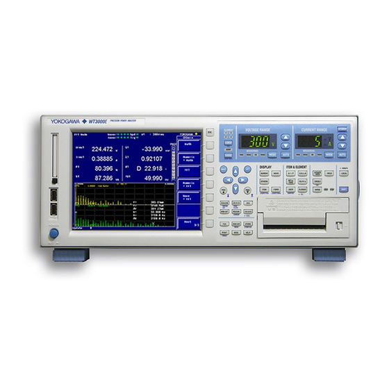
Chapter 1 Motor Evaluation Function (Option) Names and Functions of Parts of the Motor Evaluation Function Front Panel YOKOGAWA VOLTAGE RANGE CURRENT RANGE EXT SENSOR ELEMENT SENSOR RATIO ELEMENT COMPEN MEASURING MEASURING MODE AUTO MODE AUTO WIRING MEAN RMEAN MEAN RMEAN INPUT INFO. -
Page 10: Applying Signals Of Rotating Speed And Torque
Applying Signals of Rotating Speed and Torque CAUTION Applying a voltage exceeding the maximum allowable input to the revolution signal input connector (SPEED) or torque signal input connector (TORQUE) can damage the instrument. French ATTENTION L’application d’une tension supérieure à l’entrée maximale admissible au connecteur d’entrée de signal de régime (SPEED) ou au connecteur d’entrée de signal de couple (TORQUE) peut endommager l’instrument. - Page 11 1.2 Applying Signals of Rotating Speed and Torque Torque Signal Input Connector (TORQUE) Input the signal output from the torque meter (a DC voltage (analog or pulse signal) that is proportional to the torque of the motor) according to the following specifications. TORQUE 20V MAX •...
-
Page 12: Selecting The Type Of The Revolution And Torque Signals
Selecting the Type of the Revolution and Torque Signals Procedure DISPLAY ITEM & ELEMENT REMOTE RESET UPDATE NUMERIC WAVE U / I / P HOLD LOCAL RATE Cursor keys WP/q/ OTHERS SINGLE TIME PAGE PAGE ITEM FORM USER INTEG ELEMENT SHIFT START STOP... - Page 13 1.3 Selecting the Type of the Revolution and Torque Signals • Selecting the Torque Signal Type Press the cursor keys to select the Sense Type under Torque. Press SET. A signal type selection box appears. Press the cursor keys to select Analog or Pulse. Press SET to confirm the signal type.
- Page 14 1.3 Selecting the Type of the Revolution and Torque Signals • Common Settings Not Dependent on the Signal Type • Motor’s number of poles and frequency measurement source (section 1.7) • Scaling factor and unit (section 1.8) IM WT3001E-51EN...
-
Page 15: Selecting The Analog Range
Selecting the Analog Range Procedure DISPLAY ITEM & ELEMENT REMOTE RESET UPDATE NUMERIC WAVE U / I / P HOLD LOCAL RATE Cursor keys WP/q/ OTHERS SINGLE TIME PAGE PAGE ITEM FORM USER ELEMENT INTEG SHIFT START STOP LOWER ITEM LOWER FORM USER SET To exit the menu during operation, press ESC located above the... - Page 16 1.4 Selecting the Analog Range • When Measuring Using a Fixed Range (When Auto Range Is Set to OFF) Press the cursor keys to select Range under Speed. Press SET. An input range selection box appears. Press the cursor keys to select a value between 20 V to 1 V. Press SET to confirm the input range.
- Page 17 1.4 Selecting the Analog Range Explanation • Selecting the Input Range of the Revolution and Torque Signals Two types of range settings are available: fixed and auto. • Fixed Range Select the input range from the following: 20 V, 10 V, 5 V, 2 V, or 1 V •...
-
Page 18: Selecting The Line Filter And Synchronization Source
Selecting the Line Filter and Synchronization Source Procedure DISPLAY ITEM & ELEMENT REMOTE RESET UPDATE NUMERIC WAVE U / I / P HOLD LOCAL RATE Cursor keys WP/q/ OTHERS SINGLE TIME PAGE PAGE ITEM FORM USER ELEMENT INTEG SHIFT START STOP LOWER ITEM LOWER FORM... - Page 19 1.5 Selecting the Line Filter and Synchronization Source Explanation • Selecting the Line Filter A line filter can be inserted into the circuits that measure the revolution signal and torque signal. It eliminates harmonic noise. The cutoff frequency can be selected from the list of choices below. OFF, 100 Hz, and 50 kHz Selecting OFF disables the filter.
-
Page 20: Setting The Pulse Range, Pulse Count, And Pulse Rating
Setting the Pulse Range, Pulse Count, and Pulse Rating Procedure DISPLAY ITEM & ELEMENT REMOTE RESET UPDATE NUMERIC WAVE U / I / P HOLD LOCAL RATE Cursor keys WP/q/ OTHERS SINGLE TIME PAGE PAGE ITEM FORM USER ELEMENT INTEG SHIFT START STOP... - Page 21 1.6 Setting the Pulse Range, Pulse Count, and Pulse Rating • Setting the Pulse Input Range of the Torque Signal If the torque signal type is Pulse, set the upper and lower limits of the pulse input range. Press the cursor keys to select Pulse Range Upper under Torque. Press SET.
- Page 22 1.6 Setting the Pulse Range, Pulse Count, and Pulse Rating • Setting the Pulse Rating of the Torque Signal Set the pulse rating of the torque sensor. • Setting the Positive Rating Press the cursor keys to select Pulse Rated Upper under Torque. Press SET.
- Page 23 1.6 Setting the Pulse Range, Pulse Count, and Pulse Rating Explanation • Pulse Input Range Set an appropriate range that includes the maximum and minimum values of the input signal. For example, if you are measuring a signal whose rotating speed is between 120 rpms and 180 rpms and the torque is between –18 N·m to +18 N·m, set the pulse input range of the rotating speed to 100 rpms to 200 rpms and that of the torque to –20 N·m to +20 N·m.
- Page 24 1.6 Setting the Pulse Range, Pulse Count, and Pulse Rating • Relationship between the Pulse Input Range and Pulse Rating of the Torque Signal If the torque sensor with the specifications below is used to measure the torque in the range of –20 N·m to +20 N·m, the pulse input range and pulse rating settings are as shown in the scree example below.
-
Page 25: Setting The Scaling Factor And Unit
Setting the Scaling Factor and Unit Procedure DISPLAY ITEM & ELEMENT REMOTE RESET UPDATE NUMERIC WAVE U / I / P HOLD LOCAL RATE Cursor keys WP/q/ OTHERS SINGLE TIME PAGE PAGE ITEM FORM USER ELEMENT INTEG SHIFT START STOP LOWER ITEM LOWER FORM USER SET... - Page 26 1.7 Setting the Scaling Factor and Unit • Setting the Unit of Rotating Speed Press the cursor keys to select Unit under Speed. Press SET. A keyboard appears. Use the keyboard to set the unit. For keyboard operations, see section 3.14 in the User’s Manual IM WT3001E-01EN. •...
- Page 27 1.7 Setting the Scaling Factor and Unit • Setting the Scaling Factor Used to Compute the Motor Output Press the cursor keys to select Scaling under Pm. Press SET. A scaling factor entry box appears. Press the cursor keys to set the scaling factor. Press SET or ESC to close the box.
- Page 28 1.7 Setting the Scaling Factor and Unit Explanation • Setting the Scaling Factor Used to Transform the Revolution Signal Set the factor used to transform the revolution signal. Set the value in the range of 0.0001 to 99999.9999. • When the Revolution Signal Type is Analog By setting the number of rotations per volt of input voltage, the rotating speed is derived from the following equation.
-
Page 29: Setting The Motor And Frequency Measurement Source For Computing The Sync Speed And Slip
Setting the Motor and Frequency Measurement Source for Computing the Sync Speed and Slip Procedure DISPLAY ITEM & ELEMENT REMOTE RESET UPDATE NUMERIC WAVE U / I / P HOLD LOCAL RATE Cursor keys WP/q/ OTHERS SINGLE TIME PAGE PAGE ITEM FORM USER... - Page 30 1.8 Setting the Motor and Frequency Measurement Source for Computing the Sync Speed and Slip • Selecting the Frequency Measurement Source Signal (Voltage or Current Signal Supplied to the Motor) Press the cursor keys to select Sync Speed Source. Press SET. A frequency measurement source selection box appears. Press the cursor keys to select any of the target input signals for frequency measurement (see section 5.3 in the User’s Manual IM WT3001E-01EN).
- Page 31 1.8 Setting the Motor and Frequency Measurement Source for Computing the Sync Speed and Slip • Equation for Deriving the Slip –1 The unit of synchronous speed is fixed to min (or rpm). Therefore, to determine the slip, set the scaling coefficient of the rotating speed (see section 1.7) so that the unit of rotating speed s also min –1 (or rpm).
-
Page 32: Computing The Motor Efficiency And Total Efficiency
Computing the Motor Efficiency and Total Efficiency From the active power that this instrument measures and the motor output determined in section 1.7, this instrument can compute the motor efficiency (the ratio of the motor output versus the power consumption by the motor) and total efficiency. Set the equation according to the procedures given in section 5.7 or 5.4 in the User’s Manual IM WT3001E-01EN. -
Page 33: Specifications Of The Motor Evaluation Function
1.10 Specifications of the Motor Evaluation Function Input Signal Item Specifications Rotating signal and torque signal • For DC voltage (analog input) Item Specifications Connector type Isolated BNC connector Input range 1 V, 2 V, 5 V, 10 V, and 20 V Effective input range 0% to ±110% of the measurement range Input resistance... - Page 34 1.10 Specifications of the Motor Evaluation Function Symbols and Determination of Motor Evaluation Measurement Functions Measurement Functions during Normal Method of Determination, Equation Measurement When the type of input signal from the revolution sensor is DC voltage (analog signal) Input voltage from the revolution sensor • Scaling factor Scaling factor: Number of rotations per volt of input voltage Rotating When the type of input signal from the revolution sensor is pulse count...
-
Page 35: Chapter 2 Built-In Printer (Option)
Chapter 2 Built-in Printer (Option) Names and Functions of Parts of the Built-in Printer Front Panel YOKOGAWA VOLTAGE RANGE CURRENT RANGE EXT SENSOR ELEMENT SENSOR RATIO ELEMENT COMPEN MEASURING MEASURING MODE AUTO MODE AUTO WIRING MEAN RMEAN MEAN RMEAN INPUT INFO. -
Page 36: Loading The Roll Paper And Feeding The Paper
Loading the Roll Paper and Feeding the Paper WARNING A roll paper cutter is attached to the printer unit cover. Be careful not to injure your hand or fingers on the cutter. • Do not insert your finger into the printer unit opening where the roll paper is fed out. •... - Page 37 2.2 Loading the Roll Paper and Feeding the Paper Hook your finger in the groove on the right side of the printer unit. Groove Hold the top, bottom, and right sections of the printer unit and pull the printer unit out until it stops (approximately 5 cm).
- Page 38 2.2 Loading the Roll Paper and Feeding the Paper With approximately 10 cm of the paper unrolled, load the roll paper in the holder with the thermal-sensitive side facing up. Load the roll paper so that it fits into the guide.
- Page 39 2.2 Loading the Roll Paper and Feeding the Paper Placing your thumb on the front panel (left of the lever) of the printer, push the printer unit in until it clicks in place. Push the printer unit in until it clicks in place.
- Page 40 Explanation • Printer Roll Paper Use only the dedicated roll paper provided by YOKOGAWA. Do not use other types of roll paper. When using the printer for the first time, use the roll paper that is included in the package. Order extra rolls from your nearest YOKOGAWA dealer.
-
Page 41: Printing Screen Images On The Built-In Printer
Printing Screen Images on the Built-in Printer Procedure DISPLAY ITEM & ELEMENT REMOTE RESET UPDATE U / I / P NUMERIC WAVE HOLD LOCAL RATE Cursor keys WP/q/ OTHERS SINGLE TIME PAGE PAGE ITEM FORM USER ELEMENT INTEG SHIFT START STOP LOWER ITEM LOWER FORM... - Page 42 2.3 Printing Screen Images on the Built-in Printer • Setting Comments Press the Comment soft key. A keyboard appears. Use the keyboard to enter the comment. For keyboard operations, see section 3.14, “Entering Values and Strings” in the User’s Manual IM WT3001E-01EN. •...
-
Page 43: Printing Numeric Data Lists On The Built-In Printer
Printing Numeric Data Lists on the Built-in Printer Procedure DISPLAY ITEM & ELEMENT REMOTE RESET UPDATE NUMERIC WAVE U / I / P HOLD LOCAL RATE Cursor keys WP/q/ OTHERS SINGLE TIME PAGE PAGE ITEM FORM USER ELEMENT INTEG SHIFT START STOP LOWER ITEM... - Page 44 2.4 Printing Numeric Data Lists on the Built-in Printer • Selecting the Numerical Data to Be Printed Press the List Item soft key to display the List Item dialog box. • Selecting the Items at Once Press the cursor keys to select All ON. Press SET.
- Page 45 2.4 Printing Numeric Data Lists on the Built-in Printer • Printing or Not Printing (ON/OFF) the Header Information Press the Information soft key to select ON or OFF. • Executing the Print Operation Press PRINT to print the numeric data list. •...
-
Page 46: Auto Print
Auto Print Procedure DISPLAY ITEM & ELEMENT REMOTE RESET UPDATE NUMERIC WAVE U / I / P HOLD LOCAL RATE Cursor keys WP/q/ OTHERS SINGLE TIME PAGE PAGE ITEM FORM USER ELEMENT INTEG SHIFT START STOP LOWER ITEM LOWER FORM USER SET To exit the menu during operation, press ESC located above the SCALING... - Page 47 2.5 Auto Print Print Timer Synchronized Auto Print • Setting the Reservation Time Press the cursor keys to select one of the reservation year, month, date, hour, minute, and second boxes for specifying when the printing will start (Start Time). Press SET to display the entry box.
- Page 48 2.5 Auto Print Integration Synchronized Auto Print • Setting the Print Interval Press the cursor keys to select the hour, minute, or second box of the print interval. Press SET to display the entry box. Press the cursor keys to set the hour, minute, or second that you selected in step 5. Press SET or ESC to close the box.
- Page 49 2.5 Auto Print Explanation When auto print is used, screen images and numeric data lists can be printed automatically on the built-in printer at the specified print interval. • Limitations on the Auto Print Function by Measurement Modes There are limitations on the setting and execution of auto print in measurement modes other than normal measurement mode.
- Page 50 2.5 Auto Print • Setting the Print Interval Set the time interval for carrying out auto print in hour:minute:second. The selectable range varies depending on the data update interval as follows: • When the data update interval is less than 10 s: 00:00:10 to 99:59:59 •...
- Page 51 2.5 Auto Print • Print Timing of the Print Timer Synchronized Auto Print • When the start time is before turning Auto Print ON Start time Auto Print ON Auto print OFF or end time PRINT key illuminated PRINT key turned OFF Print interval Print interval...
-
Page 52: Built-In Printer Specifications
Built-in Printer Specifications Item Specifications Print system Thermal line dot system Dot density 8 dots/mm Paper width 112 mm Printing width 104 mm Auto print Set the print interval to automatically print the measured values. Set the start and end times. 2-18 IM WT3001E-51EN... - Page 53 Chapter 3 D/A Output and Remote Control (Option) Part Names and Functions of D/A Output Front Panel YOKOGAWA VOLTAGE RANGE CURRENT RANGE EXT SENSOR ELEMENT SENSOR RATIO ELEMENT COMPEN MEASURING MEASURING MODE AUTO MODE AUTO WIRING MEAN RMEAN MEAN RMEAN INPUT INFO.
- Page 54 3.1 Part Names and Functions of D/A Output Functional Description • D/A Output The numeric data measured on this instrument can be output as analog signals to other instruments. The analog signal is DC voltage of ±5 V FS. The numeric data of up to 20 items can be output.
-
Page 55: Setting The D/A Output
Setting the D/A Output Procedure DISPLAY ITEM & ELEMENT REMOTE RESET UPDATE U / I / P NUMERIC WAVE HOLD LOCAL RATE Cursor keys WP/q/ OTHERS SINGLE TIME PAGE PAGE ITEM FORM USER ELEMENT INTEG SHIFT START STOP LOWER ITEM LOWER FORM USER SET To exit the menu during operation, press ESC located above the... - Page 56 3.2 Setting the D/A Output Setting the D/A Output Items • Selecting the Target Channel Press the cursor keys to select a value between 1 and 20. • Selecting the Measurement Function Press the Function soft key. The measurement function selection box appears. Press the cursor keys to select any of the measurement functions starting with None.
- Page 57 3.2 Setting the D/A Output Setting the Rated Time of Integrated D/A Output Press INTEG to display the Integ menu. Press the Integ Set soft key to display the Integ Set menu. Press the D/A Output Rated Time soft key to display the D/A Rated Time dialog box.
- Page 58 3.2 Setting the D/A Output Explanation The numeric data can be output using ± 5-V FS DC voltage from the D/A output connector on the rear panel. Up to 20 items (channels) can be specified. CAUTION Do not short the D/A output terminal or apply external voltage to it. If you do, the instrument may malfunction.
- Page 59 3.2 Setting the D/A Output • Selecting the Element/Wiring Unit • You can select the element/wiring unit from the choices below. The selectable items vary depending on the installed elements. Element1, Element2, Element3, Element4, ΣA, and ΣB • If there are no elements that are assigned to the selected wiring unit, there is no numeric data.
- Page 60 3.2 Setting the D/A Output Rated Time of Integrated D/A Output In the case of integrated values, the integrated value that is obtained while continuously applying a rated value (same value as the measurement range) for the specified time is taken to be 100%.
- Page 61 3.2 Setting the D/A Output • Other Items D/A output Display value Output Approx. 7.5 V Approx. 7.0 V 140% Approx. 7.0 V 100% 5.0 V 5.0 V –100% –5.0 V –140% Approx. –7.0 V –140 –100 Display value [%] –5.0 V Approx.
-
Page 62: Setting The D/A Zoom
Setting the D/A Zoom Procedure DISPLAY ITEM & ELEMENT REMOTE RESET UPDATE NUMERIC WAVE U / I / P HOLD LOCAL RATE Cursor keys WP/q/ OTHERS SINGLE TIME PAGE PAGE ITEM FORM USER ELEMENT INTEG SHIFT START STOP LOWER ITEM LOWER FORM USER SET To exit the menu during operation, press ESC located above the... - Page 63 3.3 Setting the D/A Zoom Explanation • D/A Zoom The D/A output can be magnified or reduced for each channel in manual range mode by setting the D/A output range. For example, if a current varying in the range of 0.6 A to 0.8 A is measured at the 1-A range and the D/A output is set to fixed range mode, the D/A output voltage varies between 3.0 V and 4.0 V.
-
Page 64: Remote Control
Remote Control • Remotely Controlling the Integration Enter the signals according to the timing chart below. Start Stop Reset Start Stop 10 ms or more EXT START 10 ms or more EXT STOP 10 ms or more EXT RESET 100 ms or less 100 ms or less 1 s or less 1 s or less... - Page 65 3.4 Remote Control Explanation Hold, single measurement, integration start/stop/reset, and print output can be controlled externally. CAUTION Do not apply voltage outside the range of 0 to 5 V to the remote control input pins. Also, do not short the output pins or apply external voltage to them. If you do, the instrument may malfunction.
-
Page 66: D/A Output And Remote Control Specifications
D/A Output and Remote Control Specifications D/A Output Item Specifications D/A conversion resolution 16 bits Output voltage ±5 V FS (approx. ±7.5 V maximum) against each rated value. Update interval The same as the data update interval of this instrument Number of outputs 20 channels Output item for each channel specifiable. -
Page 67: Chapter 4 Rgb Video Signal (Vga) Output (Option)
Chapter 4 RGB Video Signal (VGA) Output (Option) Names and Functions of the Parts of the RGB Video Signal (VGA) Output Rear Panel RGB video signal (VGA) output VIDEO-OUT (VGA) connector Outputs image signals. The screen of this instrument can be output to a monitor through the RGB video signal (VGA) output. - Page 68 4.1 Names and Functions of the Parts of the RGB Video Signal (VGA) Output Connecting to the Monitor Turn OFF this instrument and the monitor. Connect this instrument and the monitor using an analog RGB cable. The screen of this instrument appears on the monitor when both this instrument and the monitor are turned ON.
-
Page 69: Rgb Video Signal (Vga) Output Specifications
RGB Video Signal (VGA) Output Specifications Item Specifications Connector type D-sub 15 pin (receptacle) Output type VGA compatible Index IM WT3001E-51EN... -
Page 70: Chapter 5 Ethernet Communications (Option)
Chapter 5 Ethernet Communications (Option) Connecting to the Network When Connecting to a PC on the Network Turn OFF the power switch of this instrument(see section 3.4 in the User’s Manual IM WT3001E-01EN). Connect one end of the UTP (or STP) cable to the ETHERNET 100BASE-TX terminal on the rear panel. -
Page 71: Setting Tcp/Ip
Setting TCP/IP Procedure DISPLAY ITEM & ELEMENT REMOTE RESET UPDATE NUMERIC WAVE U / I / P HOLD LOCAL RATE Cursor keys WP/q/ OTHERS SINGLE TIME PAGE PAGE ITEM FORM USER ELEMENT INTEG SHIFT START STOP LOWER ITEM LOWER FORM USER SET To exit the menu during operation, press ESC located above the SCALING... - Page 72 5.2 Setting TCP/IP When Using Only DHCP Press the cursor keys to select DHCP. Press SET to select ON. Press the cursor keys to select DNS. Press SET. A DNS selection box appears. Press the cursor keys to select OFF. When Using Only DNS Press the cursor keys to select DHCP.
- Page 73 5.2 Setting TCP/IP • Turning ON the DNS Press the cursor keys to select DNS. Press SET. A DNS selection box appears. Press the cursor keys to select ON. Press SET to confirm the DNS ON setting. • Entering the Domain Name Enter the domain name of the system or network to which this instrument belongs.
- Page 74 5.2 Setting TCP/IP When Using Both DHCP and DNS Press the cursor keys to select DHCP. Press SET to select ON. Press the cursor keys to select DNS. Press SET. A DNS selection box appears. Press the cursor keys to select ON or Auto. If you selected ON, you must enter information according to “Entering the Domain Name”...
- Page 75 5.2 Setting TCP/IP • IP Address (Internet Protocol Address) You can set the IP address assigned to this instrument. The default setting is 0.0.0.0. • The IP address is an ID that is assigned to each device on an IP network such as the internet or an intranet.
- Page 76 5.2 Setting TCP/IP • DNS Server Address • Set the IP address of the DNS server. The default setting is 0.0.0.0. • You can specify up to two DNS server addresses, primary and secondary. If the primary DNS server is down, the secondary DNS server is automatically looked up for the mapping of the host name/domain name and IP address.
- Page 77 5.2 Setting TCP/IP Configuring the TCP/IP Settings of the PC Communication parameters such as the IP address must be specified also on the PC side. Communication parameters are specified for each Ethernet NIC that is installed in the PC. Here, the settings of the NIC required for connecting your PC and this instrument are explained.
-
Page 78: Saving Setup, Waveform Display, Numeric, And Image Data To The Ftp Server (Ftp Client Function)
Saving Setup, Waveform Display, Numeric, and Image Data to the FTP Server (FTP Client Function) Procedure DISPLAY ITEM & ELEMENT REMOTE RESET UPDATE U / I / P NUMERIC WAVE HOLD LOCAL RATE Cursor keys WP/q/ OTHERS SINGLE TIME PAGE PAGE ITEM FORM... - Page 79 5.3 Saving Setup, Waveform Display, Numeric, and Image Data to the FTP Server (FTP Client Function) • Specifying the Save Destination FTP Server Press the cursor keys to select FTP Server. Press SET. A keyboard appears. Use the keyboard to enter the IP address of the FTP server. If you are using DNS, you can specify the server by name.
- Page 80 5.3 Saving Setup, Waveform Display, Numeric, and Image Data to the FTP Server (FTP Client Function) Explanation The FTP client function of this instrument can be used to save the setup parameters, waveform display data, numeric data, and screen image data to an FTP server on the network in a similar fashion to saving various data on a PC card.
-
Page 81: Printing Screen Images On A Network Printer
Printing Screen Images on a Network Printer Procedure DISPLAY ITEM & ELEMENT REMOTE RESET UPDATE NUMERIC WAVE U / I / P HOLD LOCAL RATE Cursor keys WP/q/ OTHERS SINGLE TIME PAGE PAGE ITEM FORM USER ELEMENT INTEG SHIFT START STOP LOWER ITEM LOWER FORM... - Page 82 5.4 Printing Screen Images on a Network Printer • Specifying the Printer Server Press the cursor keys to select LPR Server. Press SET. A keyboard appears. Use the keyboard to enter the IP address of the printer server. If you are using DNS, you can specify the server by name.
- Page 83 5.4 Printing Screen Images on a Network Printer • Selecting the Resolution (This procedure is applicable if you selected BJ in step 5.) Press the BJ Reso soft key to display the Resolution menu. Press any soft key from 180dpi to 360dpi to select the resolution •...
- Page 84 5.4 Printing Screen Images on a Network Printer Explanation The LPR client function of this instrument can be used to output screen images to a network printer. • Printer Server • Specify the printer server by entering the IP address. •...
-
Page 85: Sending E-Mail
Sending E-mail Procedure DISPLAY ITEM & ELEMENT REMOTE RESET UPDATE NUMERIC WAVE U / I / P HOLD LOCAL RATE Cursor keys WP/q/ OTHERS SINGLE TIME PAGE PAGE ITEM FORM USER ELEMENT INTEG SHIFT START STOP LOWER ITEM LOWER FORM USER SET To exit the menu during operation, press ESC located above the SCALING... - Page 86 5.5 Sending E-mail • Specifying the Mail Server Press the cursor keys to select Mail Server. Press SET. A keyboard appears. Use the keyboard to enter the IP address of the mail server. If you are using DNS, you can specify the server by name. For keyboard operations, see section 3.14 in the User’s Manual IM WT3001E-01EN.
- Page 87 5.5 Sending E-mail • Performing a Test Transmission Press the cursor keys to select Mail Test. Press SET. A test mail is sent to the destination. Explanation The condition of this instrument can be sent in e-mail messages at a certain interval to a specified mail destination.
-
Page 88: Accessing This Instrument From A Pc Or Workstation (Ftp Server Function)
Accessing this instrument from a PC or Workstation (FTP Server Function) Procedure DISPLAY ITEM & ELEMENT REMOTE RESET UPDATE NUMERIC WAVE U / I / P HOLD LOCAL RATE Cursor keys WP/q/ OTHERS SINGLE TIME PAGE PAGE ITEM FORM USER ELEMENT INTEG SHIFT... - Page 89 5.6 Accessing this instrument from a PC or Workstation (FTP Server Function) • Setting the User Name Press the cursor keys to select User Name. Press SET to display the keyboard. Use the keyboard to enter the user name. • For keyboard operations, see section 3.14 in the User’s Manual IM WT3001E-01EN. •...
- Page 90 5.6 Accessing this instrument from a PC or Workstation (FTP Server Function) • Displaying the Logging List Press the Connect Log List soft key. This instrument access log is displayed. Explanation You can access the PC card in this instrument or USB memory (option) from a PC or workstation on the network.
- Page 91 5.6 Accessing this instrument from a PC or Workstation (FTP Server Function) Note • This instrument supports only a single client. • When this instrument is accessed from the PC or workstation (login), is displayed in the upper left corner of the screen. •...
-
Page 92: Setting Of The Time Difference From Gmt Or Sntp
Setting of the Time Difference from GMT or SNTP Procedure DISPLAY ITEM & ELEMENT REMOTE RESET UPDATE NUMERIC WAVE U / I / P HOLD LOCAL RATE Cursor keys WP/q/ OTHERS SINGLE TIME PAGE PAGE ITEM FORM USER ELEMENT INTEG SHIFT START STOP... - Page 93 5.7 Setting of the Time Difference from GMT or SNTP • Setting SNTP (Simple Network Time Protocol) Press the cursor keys to select Exec at Power On under SNTP. Press SET to select ON or OFF. Press the cursor keys to select Server. Press SET to display the keyboard.
-
Page 94: Checking The Ethernet Communication Function (Option) Availability And Mac Address
MAC address is displayed under Mac Address in the System Overview window. Note Index The MAC address is displayed only on products with the Ethernet communication function. If the MAC address is displayed as “xxxxxx_xxx_xxx” even though the Ethernet communication function is installed, contact your nearest YOKOGAWA dealer. 5-25 IM WT3001E-51EN... - Page 95 Setting the FTP Passive Mode and LPR/SMTP Timeout Procedure DISPLAY ITEM & ELEMENT REMOTE RESET UPDATE NUMERIC WAVE U / I / P HOLD LOCAL RATE Cursor keys WP/q/ OTHERS SINGLE TIME PAGE PAGE ITEM FORM USER INTEG ELEMENT SHIFT START STOP LOWER ITEM...
-
Page 96: Setting The Ftp Passive Mode And Lpr/Smtp Timeout
5.9 Setting the FTP Passive Mode and LPR/SMTP Timeout • Turning ON/OFF the FTP Passive Mode Press the cursor keys to select FTP Passive. Press SET to select ON or OFF. • Setting the LPR Timeout Value Press the cursor keys to select LPR Time Out. Press SET. -
Page 97: Ethernet Interface Specifications
5.10 Ethernet Interface Specifications Item Specifications Number of communication ports Connector type RJ-45 connector Electrical and mechanical specifications Conforms to IEEE 802.3. Transmission system Ethernet (100BASE-TX/10BASE-T) Data rate 100 Mbps maximum Communication protocol TCP/IP Supported service FTP client Save setup parameters, waveform display data, numeric data, and screen image data to an FTP server (network drive) on the network. - Page 98 Chapter 6 Delta Computation Delta Computation Function Functional Overview The sum or difference of the instantaneous values (sampled data) of the voltage or current between the elements in a wiring unit can be used to determine various types of data such as the differential voltage and phase voltage. This operation is called delta computation.
-
Page 99: Setting The Delta Computation
Setting the Delta Computation Procedure To exit the menu during VOLTAGE RANGE CURRENT RANGE EXT SENSOR ELEMENT operation, press ESC located SENSOR RATIO above the soft keys. In the procedural explanation ELEMENT below, the phrase “press the cursor keys” may be used. COMPEN This phrase refers to the MEASURING... - Page 100 6.2 Setting the Delta Computation Explanation In the normal measurement of U and I, the sum or difference of the instantaneous values (sampled data) of the voltage or current between the elements assigned to the target wiring unit for the delta computation can be used to determine the measurement functions, ∆U and ∆I. This operation is called delta computation. For the equations, see section 6.3.
- Page 101 6.2 Setting the Delta Computation • Star>Delta Computes various data of a delta connection from the data of a star connection (star- delta transformation) using the data from a three-phase, four-wire system. ∆F1[UrsA] ∆F2[UstA] ∆F3[UtrA] ∆F4[InA] UrsA UtrA UstA • Delta>Star Computes various data of a star connection from the data of a delta connection (delta- star transformation) using the data from a three-voltage, three-current system.
- Page 102 Determination of Delta Computation Delta Computation Type, Sampled Data, and Measurement Function of Delta Computation The sampled data in the table are substituted in the equations of the voltage U and current I, and the computed result is determined. The synchronization source for the delta computation is the synchronization source (Sync Src) that is assigned to the first input element (smallest number) of the wiring unit on which delta computation is to be performed.
-
Page 103: Delta Computation Specifications
Delta Computation Specifications Item Specifications difference Differential voltage and differential current determined by computation 3P3W→3V3A Line voltage and phase current that are not measured but can be computed for a three-phase, three-wire system DELTA→STAR Line voltage and neutral line current that can be computed for a three- phase, three-wire (3V3A) system STAR→DELTA Neutral line voltage and neutral line current that can be computed for a three-... -
Page 104: Chapter 7 Harmonic Measurement In Normal Measurement Mode (Option)
Chapter 7 Harmonic Measurement in Normal Measurement Mode (Option) Harmonic Measurement Function Harmonic measurement can be used to measure the harmonic components of the voltage, current, and power as well as measurement functions such as the phase angle of each harmonic order with respect to the fundamental signal. It can also be used to compute the harmonic distortion of the voltage and current. - Page 105 7.1 Harmonic Measurement Function Functional Limitations by Measurement Modes Wide bandwidth harmonic measurement mode and IEC harmonic measurement mode perform internal computation differently from other measurement modes in order to achieve the respective harmonic measurement functions. Therefore, some functions such as waveform or bar graph display on the screen, store function, motor evaluation function (option) cannot be used in these measurement modes.
- Page 106 7.1 Harmonic Measurement Function Likewise, the computing method of active power P, apparent power S, reactive power Q, power factor λ, and phase angle φ also varies by measurement mode, and the frequency components that are included differ. • Elements Element refers to a set of input terminals that can input a single phase of voltage and current to be measured.
- Page 107 7.1 Harmonic Measurement Function Types of Harmonic Measurement Functions The data (numeric data) of harmonic measurement functions is measured or computed from the sampled data described later in “Measurement Period.” * See the description of the sampled data in “Types of Measurement Functions during Normal Measurement”...
- Page 108 7.1 Harmonic Measurement Function • Harmonic Measurement Function That Indicates the Phase Difference (φ) of the Voltage and Current between the Input Elements There are five harmonic measurement functions that express the phase difference (φ). φUi-Uj, φUi-Uk, φUi-Ii, φUi-Ij, and φUi-Ik (where i, j, and k are input element numbers) Explanation is given for the case when the number of installed input elements is 4, elements 1, 2, and 3 are assigned to wiring unit ΣA using a three-phase, four-wire system.
- Page 109 7.1 Harmonic Measurement Function Measurement Period of Harmonic Measurement Functions The measurement period is the first 9000 points from the beginning of the data update interval at the harmonic sampling frequency. The sampling frequency for harmonic measurement is automatically determined in this instrument from the period of the signal set as the PLL source.
- Page 110 7.1 Harmonic Measurement Function • Dual List The data of two measurement functions is displayed in its own column. You can select the following measurement functions: U, I, P, S, Q, λ, φ, φU, φI, Z, Rs, Xs, Rp, and Xp. Measurement function 1 Measurement function 2 Numeric data of Relative harmonic content of each harmonic each harmonic order (Uhdf, Ihdf, and Phdf are displayed when the selected measurement function are U, I, and...
- Page 111 7.1 Harmonic Measurement Function Bar Graph Display «For procedures, see section 7.7.» The amplitude of each harmonic can be displayed on the bar graph. The horizontal axis represents harmonic order, and the vertical axis represents the amplitude of each harmonic. The harmonic measurement functions, elements, and order to be displayed can be specified.
- Page 112 7.1 Harmonic Measurement Function • Vector Display When the Wiring System Is 3P4W (Three-Phase, Four-Wire) U1(1), U2(1), and U3(1) are common mode voltages. I1(1), I2(1), and I3(1) are line currents. I1(1) U1(1) φ1(1), φU1-I1 φU1-U2 φU1-I2 φU1-I3 U2(1) φ3(1) I3(1) φ2(1) U3(1) φU1-U3...
-
Page 113: Setting The Measurement Mode And Displaying Numeric Data
Setting the Measurement Mode and Displaying Numeric Data Procedure To exit the menu during VOLTAGE RANGE CURRENT RANGE EXT SENSOR ELEMENT operation, press ESC located SENSOR RATIO above the soft keys. In the procedural explanation ELEMENT below, the phrase “press the cursor keys”... - Page 114 7.2 Setting the Measurement Mode and Displaying Numeric Data Explanation • Meaning of the Measurement Function Symbols For the meanings of the measurement function symbols that are displayed, see section 7.1, “Harmonic Measurement Function” or 7.11, “Harmonic Measurement Specifications.” Example harmonic voltage of element 2 U2(20) 20th order...
- Page 115 Setting the Number of Displayed Items, Page Scrolling the Display Procedure To exit the menu during VOLTAGE RANGE CURRENT RANGE EXT SENSOR ELEMENT operation, press ESC located SENSOR RATIO above the soft keys. In the procedural explanation ELEMENT below, the phrase “press the cursor keys”...
- Page 116 7.3 Setting the Number of Displayed Items, Page Scrolling the Display • When Numeric Form (the Number of Displayed Items) Is Single List or Dual List Press ESC to clear the soft menu. Press the cursor keys (left and right keys) to move the cursor to the left, center, or right column of the screen.
- Page 117 7.3 Setting the Number of Displayed Items, Page Scrolling the Display • Single List • When the display mode is Numeric, 42 numeric data values for a single measurement function are displayed in two columns. • When the display mode is not Numeric, 22 numeric data values for a single measurement function are displayed in two columns.
- Page 118 7.3 Setting the Number of Displayed Items, Page Scrolling the Display • When ALL is selected The first page is constantly displayed in the upper half of the screen, and page 2 and subsequent pages are switched in the lower half. The first page is always displayed.
-
Page 119: Changing The Displayed Items Of Numeric Data
Changing the Displayed Items of Numeric Data Procedure To exit the menu during VOLTAGE RANGE CURRENT RANGE EXT SENSOR ELEMENT operation, press ESC located SENSOR RATIO above the soft keys. In the procedural explanation ELEMENT below, the phrase “press the cursor keys”... - Page 120 7.4 Changing the Displayed Items of Numeric Data • Changing the Measurement Function Press the U/I/P, S/Q/λ/φ, WP/q/Time, or FU/FI/η function select key to select the displayed measurement function. • When the display mode is set to Single List or Dual List, only the measurement functions that contain harmonic order data can be selected.
- Page 121 7.4 Changing the Displayed Items of Numeric Data Selecting the Displayed Items from the Menu Press ITEM to display the Numeric menu. • Selecting the Item to Be Changed Press the Item No. soft key. Press the cursor keys to select the item to be changed. The item to be changed is highlighted.
- Page 122 7.4 Changing the Displayed Items of Numeric Data Selecting the Harmonic Order on the ALL Display Press PAGE to display the harmonic order data page (page 6 or page 7). Press FORM to display the Numeric Form menu. Press the cursor keys to set the order. Resetting the Order of the Displayed Items Press ITEM to display the Numeric menu.
- Page 123 7.4 Changing the Displayed Items of Numeric Data Explanation The following limitations on changing the displayed items exist depending on Item Amount (the number of displayed items). Number of Displayed Items Changing the Displayed Items 4 Items, 8 Items, 16 Items The displayed item cannot be changed independently.
- Page 124 7.4 Changing the Displayed Items of Numeric Data • When Numeric Form (the Number of Displayed Items) Is Single List or Dual List Two types of lists are available for displaying the harmonic order data. When set to Single List, the data of List Item No. 1 is displayed using two columns. When set to Dual List, the data of List Item No.
-
Page 125: Selecting The Pll Source
Selecting the PLL Source Procedure DISPLAY ITEM & ELEMENT REMOTE RESET UPDATE WAVE U / I / P NUMERIC HOLD LOCAL RATE Cursor keys WP/q/ OTHERS SINGLE TIME PAGE PAGE ITEM FORM USER ELEMENT INTEG SHIFT START STOP LOWER ITEM LOWER FORM USER SET To exit the menu during operation, press ESC located above the... - Page 126 7.5 Selecting the PLL Source Explanation For functional details, see section 7.1. Set the PLL (Phase Locked Loop) source that is used to determine the fundamental period, which acts as the reference in the analysis of the harmonic orders. • Displayed Position of the Selected PLL Source The selected PLL source is displayed in the upper right corner of the screen when HRM SET is pressed.
- Page 127 7.5 Selecting the PLL Source French ATTENTION L’application d’une tension comprise en dehors de la plage 0 à 5V sur le connecteur d’entrée d’horloge externe (EXT CLK) risque de provoquer un endommagement de l’instrument. Note • Select a signal that has the same period as the target signal for the harmonic measurement.
-
Page 128: Setting The Measured Order
Setting the Measured Order Procedure DISPLAY ITEM & ELEMENT REMOTE RESET UPDATE U / I / P NUMERIC WAVE HOLD LOCAL RATE Cursor keys WP/q/ OTHERS SINGLE TIME PAGE PAGE ITEM FORM USER ELEMENT INTEG SHIFT START STOP LOWER ITEM LOWER FORM USER SET To exit the menu during operation, press ESC located above the... - Page 129 7.6 Setting the Measured Order Explanation The harmonic measurement range can be specified. The harmonic orders specified here are used to determine the numeric data of the distortion factor. For details on how to determine the distortion factor, see section 7.11. •...
-
Page 130: Selecting The Distortion Factor Equation
Selecting the Distortion Factor Equation Procedure DISPLAY ITEM & ELEMENT REMOTE RESET UPDATE U / I / P NUMERIC WAVE HOLD LOCAL RATE Cursor keys WP/q/ OTHERS SINGLE TIME PAGE PAGE ITEM FORM USER ELEMENT INTEG SHIFT START STOP LOWER ITEM LOWER FORM USER SET To exit the menu during operation, press ESC located above the... -
Page 131: Setting The Anti-Aliasing Filter
Setting the Anti-Aliasing Filter Procedure DISPLAY ITEM & ELEMENT REMOTE RESET UPDATE NUMERIC WAVE U / I / P HOLD LOCAL RATE Cursor keys WP/q/ OTHERS SINGLE TIME PAGE PAGE ITEM FORM USER ELEMENT INTEG SHIFT START STOP LOWER ITEM LOWER FORM USER SET To exit the menu during operation, press ESC located above the... - Page 132 7.8 Setting the Anti-Aliasing Filter Explanation When taking the FFT by performing A/D conversion on a repetitive waveform, a phenomenon occurs in which frequency components that exceed half the frequency of the sampling frequency are detected as low frequency components. This phenomenon is called aliasing.
-
Page 133: Displaying The Bar Graph And Making Cursor Measurements
Displaying the Bar Graph and Making Cursor Measurements Procedure To exit the menu during VOLTAGE RANGE CURRENT RANGE EXT SENSOR ELEMENT operation, press ESC located SENSOR RATIO above the soft keys. In the procedural explanation ELEMENT below, the phrase “press the cursor keys”... - Page 134 7.9 Displaying the Bar Graph and Making Cursor Measurements • Changing the Element Press the Element soft key to display the element selection box. Press the cursor keys to select any of the elements/wiring units starting with Element1. Press SET. The bar graph of the selected element number is displayed. •...
- Page 135 7.9 Displaying the Bar Graph and Making Cursor Measurements • Performing Cursor Measurements Press SHIFT+MEASURE (CURSOR) to display the Cursor menu. • Turning ON/OFF Cursor Measurement Press the Bar Cursor soft key to select ON or OFF. If ON is selected, the result of the cursor measurement is displayed. •...
- Page 136 7.9 Displaying the Bar Graph and Making Cursor Measurements Explanation A display example is shown below. The vertical axis is in logarithmic scale. The word <log Scale> appears at the top section of the screen. Range of orders of the <log Scale>...
- Page 137 7.9 Displaying the Bar Graph and Making Cursor Measurements • Setting the Display Range of the Bar Graph • Set the display range of the bar graph using harmonic order. • The display range of bar graph 1 to bar graph 3 is the same. •...
-
Page 138: Displaying Vectors
7.10 Displaying Vectors Procedure To exit the menu during VOLTAGE RANGE CURRENT RANGE EXT SENSOR ELEMENT operation, press ESC located SENSOR RATIO above the soft keys. In the procedural explanation ELEMENT below, the phrase “press the cursor keys” may be used. COMPEN This phrase refers to the MEASURING... - Page 139 7.10 Displaying Vectors • Zooming in on the Vector Press the U Mag/I Mag soft key to set the cursor key target to U Mag, I Mag, or both U Mag and I Mag. • If U Mag is selected, you can zoom in on the vector of the fundamental wave U(1) of each element that is specified for harmonic measurement.
- Page 140 7.10 Displaying Vectors Vector Display Examples When Displaying Numeric Data (the size of the signal and the phase difference between signals) For a 3P4W (three-phase four-wire) For a 3V3A (three-voltage, three- For a 3P3W (three-phase three-wire) wiring system current) wiring system wiring system •...
- Page 141 7.11 Harmonic Measurement Specifications Item Specifications Measured source All installed elements Format PLL synchronization method Frequency range Fundamental frequency of the PLL source is in the range of 10 Hz to 2600 Hz. PLL source • Select the voltage or current of each input element (external current sensor range is greater than or equal to 500 mV) or the external clock (Ext Clk).
- Page 142 7.11 Harmonic Measurement Specifications Item Specifications Accuracy On models with the advanced computation (/G6) option • When the line filter (5.5 kHz) is ON Frequency Voltage and Current Power ±(reading error + measurement ±(reading error + measurement range error) range error) 10 Hz ≤ f < 30 Hz 0.25% of reading + 0.3% of range 0.5% of reading + 0.4% of range...
- Page 143 7.11 Harmonic Measurement Specifications Measurement Functions Determined for Each Input Element Item Symbol and Meaning Voltage (V) U(k): rms value of the harmonic voltage of order k U: Rms voltage (total value Current (A) I(k): rms value of the harmonic current of order k I: Rms current (total value Active power (W) P(k): Active power of the harmonic signal of order k...
- Page 144 7.11 Harmonic Measurement Specifications Measurement Functions Indicating the Phase Difference of the Fundamental Voltage and Current between Elements These measurement functions express the phase difference of fundamental wave U(1) and I(1) of other elements with respect to the fundamental wave U(1) of the element with the smallest number of the input elements that are assigned to the wiring unit.
- Page 145 7.11 Harmonic Measurement Specifications Determination of Measurement Functions during Harmonic Measurement (Table 1/3) Method of Determination, Equation Characters/Numbers inside the parentheses of Measurement Functions during measurement functions Harmonic Measurement Total {No ( )} (when k = 0) (when k = 1) (When k = 2 to max) U(k) = U(dc) =U...
- Page 146 7.11 Harmonic Measurement Specifications (Table 2/3) Method of Determination, Equation Characters/Numbers inside the parentheses of measurement Measurement Functions functions are dc (when k = 0) and k (when k = 1 to max). during Harmonic Measurement When the numerator of the distortion When the numerator of the distortion factor equation is all (Total) factor equation is fundamental...
- Page 147 7.11 Harmonic Measurement Specifications (Table 3/3) Measurement Functions Method of Determination, Equation during Harmonic Measurement Single-phase, Three-phase, Three-voltage, Three-phase, Wiring system three-wire (1P3W) three-wire (3P3W) three-current (3V3A) four-wire (3P4W) UΣ [V] (U1 + U2) / 2 (U1 + U2 + U3) / 3 IΣ...
- Page 148 Chapter 8 Wide Bandwidth Harmonic Measurement (Option) Wide Bandwidth Harmonic Measurement Function Harmonic measurement up to 50 order can be performed on a signal with a 1-kHz fundamental frequency. Use this mode for harmonic measurement of signals whose fundamental frequency is higher than the commercial power supply frequency. By applying an external sampling clock, harmonics can be measured on low frequency signals with a fundamental frequency of 0.1 Hz.
- Page 149 Various Settings Related to Wide Bandwidth Harmonic Measurement Most of the operations of wide bandwidth harmonic measurement mode are common with the harmonic measurement of normal measurement mode. A setting specific to the wide bandwidth harmonic measurement is the ON/OFF setting of the timeout warning display of the PLL lock.
-
Page 150: Selecting The Wide Bandwidth Harmonic Measurement Mode And Displaying Numeric Data
Selecting the Wide Bandwidth Harmonic Measurement Mode and Displaying Numeric Data Procedure To exit the menu during VOLTAGE RANGE CURRENT RANGE EXT SENSOR ELEMENT operation, press ESC located SENSOR RATIO above the soft keys. In the procedural explanation ELEMENT below, the phrase “press the cursor keys”... - Page 151 8.3 Selecting the Wide Bandwidth Harmonic Measurement Mode and Displaying Numeric Data • Enabling Wide Bandwidth Harmonic Measurement Mode If normal measurement mode is enabled, switch to wide bandwidth harmonic measurement mode. Press HRM SET to display the Harmonics menu. Press the Freq Band soft key to select Wide.
-
Page 152: Turning On/Off The Timeout Warning Display Of The Pll Lock
Turning ON/OFF the Timeout Warning Display of the PLL Lock Procedure DISPLAY ITEM & ELEMENT REMOTE RESET UPDATE NUMERIC WAVE U / I / P HOLD LOCAL RATE Cursor keys WP/q/ OTHERS SINGLE TIME PAGE PAGE ITEM FORM USER ELEMENT INTEG SHIFT START... -
Page 153: Wide Bandwidth Harmonic Measurement Specifications
Wide Bandwidth Harmonic Measurement Specifications Item Specifications Measured source All installed elements Format PLL synchronization method (when the PLL source is not set to Smp Clk) or external sampling clock method (when the PLL source is set to Smp Clk) Frequency range •... - Page 154 8.5 Wide Bandwidth Harmonic Measurement Specifications Item Specifications Accuracy • When the line filter (5.5 kHz) is ON Frequency Voltage and Current Power ±(reading error + measurement ±(reading error + measurement range error) range error) 0.1 Hz ≤ f < 10 Hz 0.25% of reading + 0.3% of range 0.5% of reading + 0.4% of range 10 Hz ≤ f < 30 Hz 0.25% of reading + 0.3% of range...
- Page 155 8.5 Wide Bandwidth Harmonic Measurement Specifications Frequency Measurement Item Specifications Measurement range • PLL synchronization method: 2.5 Hz ≤ f ≤ 100 kHz • External sampling clock method: 0.15 Hz ≤ f ≤ 5 kHz Measurement Function Item Specifications Display update Depends on the PLL source • PLL synchronization method: 1 s or more • External sampling clock method: 20 s or more PLL Lock Timeout Warning Item Specifications...
- Page 156 Chapter 9 IEC Harmonic Measurement (Option) IEC Harmonic Measurement Function This mode in combination with the Harmonic/Flicker Measurement Software sold separately allows you to perform harmonic measurement conforming to IEC 61000-3- 2. Use this mode to check that the harmonics of electric home appliances and office automation equipment comply with the IEC standards.
- Page 157 9.1 IEC Harmonic Measurement Function In IEC harmonic measurement, this instrument performs Fourier transform on the input signal and divides the signal into frequency components as follows: • Interharmonics If the input signal is 50 Hz, 10 periods of the waveform are divided in 5-Hz resolution. Thus, the section between each harmonic order is divided into 10 sections.
- Page 158 9.1 IEC Harmonic Measurement Function • Harmonic Subgroup A harmonic and its two directly adjacent interharmonics are collectively called harmonic subgroup. The computing method to combine the harmonic and its two adjacent interharmonics is not simple addition, but the square root of the sum of the square of each component.
- Page 159 9.1 IEC Harmonic Measurement Function • Example of Grouping Type 2 For example, the 3rd order (150-Hz) harmonic component of the 50-Hz input signal is determined by averaging the sum of the squares of the following frequency components. • 1/2 of the 125-Hz component The other 1/2 is included in the 2nd order (100-Hz) component.
- Page 160 Various Settings Related to IEC Harmonic Measurement To set the IEC harmonic measurement, use the Harmonic/Flicker Measurement Software or set this instrument according to the procedures in the respective section below before switching this instrument to remote mode using the Harmonic/Flicker Measurement Software.
-
Page 161: Selecting The Iec Harmonic Measurement Mode
Selecting the IEC Harmonic Measurement Mode Procedure To exit the menu during VOLTAGE RANGE CURRENT RANGE EXT SENSOR ELEMENT operation, press ESC located SENSOR RATIO above the soft keys. In the procedural explanation ELEMENT below, the phrase “press the cursor keys” may be used. COMPEN This phrase refers to the MEASURING... -
Page 162: Selecting The Measured Source
Selecting the Measured Source Procedure DISPLAY ITEM & ELEMENT REMOTE RESET UPDATE U / I / P NUMERIC WAVE HOLD LOCAL RATE Cursor keys WP/q/ OTHERS SINGLE TIME PAGE PAGE ITEM FORM USER ELEMENT INTEG SHIFT START STOP LOWER ITEM LOWER FORM USER SET To exit the menu during operation, press ESC located above the... -
Page 163: Selecting The Voltage/Current Grouping
Selecting the Voltage/Current Grouping Procedure DISPLAY ITEM & ELEMENT REMOTE RESET UPDATE WAVE U / I / P NUMERIC HOLD LOCAL RATE Cursor keys WP/q/ OTHERS SINGLE TIME PAGE PAGE ITEM FORM USER ELEMENT INTEG SHIFT START STOP LOWER ITEM LOWER FORM USER SET To exit the menu during operation, press ESC located above the... - Page 164 9.5 Selecting the Voltage/Current Grouping • Selecting the Current Grouping Press the I Grouping soft key to display the I Grouping menu. Press any of the soft keys from OFF, Type 1, and Type 2 to select the current grouping. Explanation •...
-
Page 165: Iec Harmonic Measurement Specifications
IEC Harmonic Measurement Specifications Item Specifications Measured source Select an input element or an Σ wiring unit Format PLL synchronization method Frequency range Fundamental frequency of the PLL source is in the range of 45 Hz to 66 Hz. PLL source • Select the voltage or current of each input element (external current sensor range is greater than or equal to 500 mV) or the external clock (fundamental frequency). - Page 166 9.6 IEC Harmonic Measurement Specifications Item Specifications Accuracy • When the line filter (5.5 kHz) is ON Frequency Voltage and Current Power ±(reading error + measurement ±(reading error + measurement range error) range error) 45 Hz ≤ f ≤ 66 Hz 0.2% of reading + 0.04% of range 0.4% of reading + 0.05% of range 66 Hz<f ≤ 440 Hz 0.5% of reading + 0.05% of range...
- Page 167 9.6 IEC Harmonic Measurement Specifications Frequency Measurement Item Specifications Measurement range 45 Hz ≤ f ≤ 1 MHz Measurement Function Item Specifications Display update Depends on the PLL source (Approximately 200 ms when the frequency of the PLL source is 45 Hz to 66 Hz.) Functional Limitations Item Specifications Display...
- Page 168 9.6 IEC Harmonic Measurement Specifications Determination of Measurement Functions Related to the IEC Harmonic Measurement Method of Determination, Equation Measurement Function When the frequency of When the frequency of the measured item is 50 Hz the measured item is 60 Hz Rms value of the harmonic subgroup of the voltage U(k+i)
- Page 169 Chapter 10 Waveform Computation (Option) 10.1 Waveform Computation Function Waveforms obtained by adding/subtracting displayed waveforms or squared or averaged waveforms can be displayed. For example, this allows the waveform of instantaneous power to be displayed by multiplying the voltage waveform by the current waveform. In addition, a cursor can be placed on the waveform to display various data at that point.
- Page 170 10.1 Waveform Computation Function • Equation Examples • Instantaneous Power Waveform To multiply the voltage waveform by the current waveform of input element 1 and display the instantaneous power waveform, set the equation to P1. • Voltage and Current Waveforms of a Three-Phase, Three-Wire System To display the voltage between the phases R and S and the current of phase T of a three-phase, three-wire system when there are only two input elements, set the equations as follows:...
- Page 171 10.2 Various Settings Related to Waveform Computation A portion of the settings related to waveform computation is common with the “waveform display in normal measurement mode” and “FFT mode.” The settings described in sections 10.3 to 10.5 are those specific to waveform computation. Set these items first. •...
-
Page 172: Setting The Waveform Computation Mode
10.3 Setting the Waveform Computation Mode Procedure To exit the menu during VOLTAGE RANGE CURRENT RANGE EXT SENSOR ELEMENT operation, press ESC located SENSOR RATIO above the soft keys. In the procedural explanation ELEMENT below, the phrase “press the cursor keys” may be used. COMPEN This phrase refers to the MEASURING... -
Page 173: Setting The Waveform Equation
10.4 Setting the Waveform Equation Procedure To exit the menu during VOLTAGE RANGE CURRENT RANGE EXT SENSOR ELEMENT operation, press ESC located SENSOR RATIO above the soft keys. In the procedural explanation ELEMENT below, the phrase “press the cursor keys” may be used. COMPEN This phrase refers to the MEASURING... - Page 174 10.4 Setting the Waveform Equation • Setting the Computing Equation Press the cursor keys to select Expression of Math1 or Math2. Press SET to display the keyboard. Use the keyboard to set the equation. For keyboard operations, see section 3.14 in the User’s Manual IM WT3001E-01EN. Display example when Expression of Math1 is selected •...
- Page 175 10.4 Setting the Waveform Equation Explanation You can create two equations (Math1 and Math2). • Setting the Equation • Operand The following operands can be combined to create an equation. There can be up to 16 operands in an equation. Operand Description U1 to U4...
- Page 176 10.4 Setting the Waveform Equation Note • If the result of the waveform computation is in error, the error data is plotted at the top edge of the screen. If this happens, the message “Math1 (Math2) Calc Error” is displayed on the screen.
-
Page 177: Setting The Scale, Unit, And Label Of The Computed Waveform
10.5 Setting the Scale, Unit, and Label of the Computed Waveform Procedure To exit the menu during VOLTAGE RANGE CURRENT RANGE EXT SENSOR ELEMENT operation, press ESC located SENSOR RATIO above the soft keys. In the procedural explanation ELEMENT below, the phrase “press the cursor keys”... - Page 178 10.5 Setting the Scale, Unit, and Label of the Computed Waveform • Setting the Scaling of the Computed Waveform • Selecting Auto or Manual Scaling Press the cursor keys to select Scale of Math1 or Math2. Press SET to display the scaling selection box. Press the cursor keys to select Auto or Manual.
- Page 179 10.5 Setting the Scale, Unit, and Label of the Computed Waveform • Setting the Unit of the Computed Waveform Press the cursor keys to select Unit of Math1 or Math2. Press SET to display the keyboard. Use the keyboard to set the unit. For keyboard operations, see section 3.14 in the User’s Manual IM WT3001E-01EN.
- Page 180 10.5 Setting the Scale, Unit, and Label of the Computed Waveform Explanation • Setting the Scale You can set the center value and the vertical zoom rate of the frame (scale/division) used to display the computed waveform. You can select the setup mode from below. •...
-
Page 181: Waveform Computation Function Specifications
10.6 Waveform Computation Function Specifications Computation Function Item Specifications Computed source Voltage, current, and active power of each input element; torque (analog input) and speed (analog input) of motor input (option); and motor output Equation Two equations (MATH1 and MATH2) Operator +, –, , /, ABS (absolute value), SQR (square), SQRT (square root), LOG (natural logarithm),... - Page 182 Chapter 11 FFT (Option) 11.1 FFT Function This function allows the power spectrum of the input signal to be displayed through FFT (fast Fourier transform). This is useful when you wish to check the frequency distribution of the input signal. Waveform of current I1 Power spectrum waveform of current I1...
- Page 183 11.1 FFT Function FFT Measurement Examples (Conceptual Diagrams) • Input signal: 52.2-Hz sine wave • Number of FFT points: 200 k (FFT measurement time: 1 s) • Left end of the graph: dc, right end: 100 Hz Rectangular Hanning Flattop Window Integral Power spectrum...
- Page 184 11.1 FFT Function • FFT Function The power spectrum can be derived from the equations below. • Voltage, Current, and Power The complex function of the voltage after taking the FFT is assumed to be U = Ur + jUj, and that of the current is assumed to be I = Ir + jIj. Power spectrum of voltage = Power spectrum of current = Power spectrum of active power = U...
- Page 185 11.2 Various Settings Related to FFT A portion of the settings related to FFT is common with the “waveform display in normal measurement mode” and “FFT mode.” The settings described in sections 11.3 to 11.9 are those specific to the FFT. Set these items first. •...
-
Page 186: Setting The Fft Mode
11.3 Setting the FFT Mode Procedure To exit the menu during VOLTAGE RANGE CURRENT RANGE EXT SENSOR ELEMENT operation, press ESC located SENSOR RATIO above the soft keys. In the procedural explanation ELEMENT below, the phrase “press the cursor keys” may be used. COMPEN This phrase refers to the MEASURING... - Page 187 11.3 Setting the FFT Mode Explanation A display example is shown below. The vertical axis is in logarithmic scale. The words <log Scale> is displayed to the right of the upper limit of the power spectrum. Frequency at the left end of Frequency at the right end of the screen of the displayed the screen of the displayed...
-
Page 188: Selecting The Power Spectrum To Be Displayed, Selecting The Fft Source, And Setting The Label
11.4 Selecting the Power Spectrum to Be Displayed, Selecting the FFT Source, and Setting the Label Procedure To exit the menu during VOLTAGE RANGE CURRENT RANGE EXT SENSOR ELEMENT operation, press ESC located SENSOR RATIO above the soft keys. In the procedural explanation ELEMENT below, the phrase “press the cursor keys”... - Page 189 11.4 Selecting the Power Spectrum to Be Displayed, Selecting the FFT Source, and Setting the Label • Selecting the FFT Source Press the FFT1 Object or FFT2 Object soft key to display the FFT source selection box. Press the cursor keys to select the FFT source. Press the SET key to confirm.
- Page 190 11.4 Selecting the Power Spectrum to Be Displayed, Selecting the FFT Source, and Setting the Label Explanation • Selecting the Power Spectrum to Be Displayed You can turn ON/OFF power spectrum 1 (FFT1) and power spectrum 2 (FFT2). • Selecting the FFT Source Select the source on which to take the FFT from below.
-
Page 191: Setting The Number Of Computed Points And Time Window
11.5 Setting the Number of Computed Points and Time Window Procedure To exit the menu during VOLTAGE RANGE CURRENT RANGE EXT SENSOR ELEMENT operation, press ESC located SENSOR RATIO above the soft keys. In the procedural explanation ELEMENT below, the phrase “press the cursor keys”... - Page 192 11.5 Setting the Number of Computed Points and Time Window • Selecting the Time Window Press the FFT Window soft key to display the FFT Window menu. Press the Rect, Hanning, or FlatTop soft key to select the time window. Explanation •...
-
Page 193: (Signal Amplitude)
11.6 Setting the Display Range of the X-Axis (Frequency) and the Scale Type of the Y-Axis (Signal Amplitude) Procedure To exit the menu during VOLTAGE RANGE CURRENT RANGE EXT SENSOR ELEMENT operation, press ESC located SENSOR RATIO above the soft keys. In the procedural explanation ELEMENT below, the phrase “press the... - Page 194 11.6 Setting the Display Range of the X-Axis (Frequency) and the Scale Type of the Y-Axis (Signal Amplitude) • Selecting the Scale Type of the Y-Axis (Signal Amplitude) Press the Vertical Scale soft key to select Lin or Log. Explanation •...
-
Page 195: Selecting The Display Type Of The Power Spectrum
11.7 Selecting the Display Type of the Power Spectrum Procedure To exit the menu during VOLTAGE RANGE CURRENT RANGE EXT SENSOR ELEMENT operation, press ESC located SENSOR RATIO above the soft keys. In the procedural explanation ELEMENT below, the phrase “press the cursor keys”... - Page 196 11.7 Selecting the Display Type of the Power Spectrum Explanation • Display Type of the Power Spectrum Select either of the two types below. • Line: The FFT data is connected with lines. The display is a line graph. • Bar: The FFT data is displayed on a bar graph. •...
-
Page 197: Displaying The Power Spectrum On The Split Screen
11.8 Displaying the Power Spectrum on the Split Screen Procedure To exit the menu during VOLTAGE RANGE CURRENT RANGE EXT SENSOR ELEMENT operation, press ESC located SENSOR RATIO above the soft keys. In the procedural explanation ELEMENT below, the phrase “press the cursor keys”... -
Page 198: Cursor Measurement
11.9 Cursor Measurement Procedure DISPLAY ITEM & ELEMENT REMOTE RESET UPDATE NUMERIC WAVE U / I / P HOLD LOCAL RATE Cursor keys WP/q/ OTHERS SINGLE TIME PAGE PAGE USER ITEM FORM ELEMENT INTEG SHIFT START STOP LOWER ITEM LOWER FORM USER SET To exit the menu during operation, press ESC located above the SCALING... - Page 199 11.9 Cursor Measurement • Turning ON/OFF Cursor Measurement Press the FFT Cursor soft key to select ON or OFF. If ON is selected, the result of the cursor measurement is displayed. • Selecting the Source FFT for Cursor Measurement • Selecting the Source FFT for Cursor + Press the FFT C1 Trace soft key to display the source FFT selection box.
- Page 200 11.9 Cursor Measurement Explanation • ON/OFF Cursors can be placed on the displayed power spectrum waveform to measure and display the value at any point. It can be used to measure the data on the vertical axis (Y-axis) and horizontal axis (X-axis) of various sections of the power spectrum waveform.
-
Page 201: Fft Function Specifications
11.10 FFT Function Specifications Computation Function Item Specifications Computed source Voltage, current, active power, and reactive power of each input element. Active power and reactive power of an Σ wiring unit. Torque and speed signals (analog input) of motor input (option). Type PS (power spectrum) Number of computations Two computations (FFT1 and FFT2) Maximum frequency of 100 kHz analysis... - Page 202 Chapter 12 Voltage Fluctuation and Flicker Measurement (Option) 12.1 Voltage Fluctuation and Flicker Measurement Function This function allows you to perform voltage fluctuation and flicker measurements conforming to IEC 61000-3-3. If you use the Harmonic/Flicker Measurement Software sold separately, you can print a report of the measurement judgement results. •...
- Page 203 12.1 Voltage Fluctuation and Flicker Measurement Function • Data Update Interval The display update interval in voltage fluctuation and flicker measurement mode is 2 s. • Limitations on the Function and Measurement Function In voltage fluctuation and flicker measurement mode, the internal computation is different from other measurement modes in order to achieve measurements conforming to the IEC standard.
- Page 204 12.1 Voltage Fluctuation and Flicker Measurement Function Period during which relative voltage change exceeds the threshold level Tmax The time during which the relative voltage change during a voltage fluctuation period exceeds the threshold level. Relationship between dc, dmax, and Tmax •...
- Page 205 12.1 Voltage Fluctuation and Flicker Measurement Function Display Example of dc Relative voltage change Steady-state condition dc display IEC 61000-4-15 Ed 1.1 Undef Undef dcC(dcC>dcD) IEC 61000-4-15 Ed 2.0 t1: Observation period 01 t2: Observation period 02 Short-Term Flicker Value Pst The method using the flicker meter is standard in IEC 61000-3-3.
- Page 206 12.1 Voltage Fluctuation and Flicker Measurement Function • Limitations on the Setting Changes and Execution of Operations in Voltage Fluctuation and Flicker Measurement Mode There are some functions whose settings cannot be changed in voltage fluctuation and flicker measurement mode as shown below. Setup Item Flicker Measurement Status Reset...
-
Page 207: Setting The Voltage Fluctuation And Flicker Measurement Mode
12.2 Setting the Voltage Fluctuation and Flicker Measurement Mode Procedure To exit the menu during VOLTAGE RANGE CURRENT RANGE EXT SENSOR ELEMENT operation, press ESC located SENSOR RATIO above the soft keys. In the procedural explanation ELEMENT below, the phrase “press the cursor keys”... - Page 208 12.2 Setting the Voltage Fluctuation and Flicker Measurement Mode Explanation • Display Related to the Voltage Fluctuation and Flicker Measurement The figure below is a display example of normal flicker measurement. Measured element Flicker Standard edition number Total judgement measurement status Display element Elapsed Measurement count...
-
Page 209: Setting The Measurement Conditions
12.3 Setting the Measurement Conditions Procedure To exit the menu during VOLTAGE RANGE CURRENT RANGE EXT SENSOR ELEMENT operation, press ESC located SENSOR RATIO above the soft keys. In the procedural explanation ELEMENT below, the phrase “press the cursor keys” may be used. COMPEN This phrase refers to the MEASURING... - Page 210 12.3 Setting the Measurement Conditions • Setting the Edition Number of IEC 61000-4-15 Press the Flicker Settings soft key to display the Flicker Settings dialog box. Press the cursor keys to select 4-15 of IEC 61000 Edition. Press SET to select Ed1.1 or Ed2.0 of IEC 61000-4-15. When the measurement When the measurement method is Flicker...
- Page 211 12.3 Setting the Measurement Conditions • Setting the Predefined Rated Voltage (valid when the assignment method is Set) Press the cursor keys to select Un Set. Press SET to display the entry box. Press the cursor keys to set the predefined value. Press SET or ESC to close the box.
- Page 212 12.3 Setting the Measurement Conditions • Setting the Measurement Count Press the cursor keys to select Count. Press SET to display the entry box. Press the cursor keys to set the measurement count. Press SET or ESC to close the box. •...
- Page 213 12.3 Setting the Measurement Conditions • Edition Number of IEC 61000-3-3 You can select the edition number of IEC 61000-3-3. • Edition 2.0 • Edition 3.0 IEC 61000-3-3 specifies the voltage fluctuation and flicker. • Measured element Set the element on which to measure the voltage fluctuation and flicker. The installed elements are displayed as possible targets.
-
Page 214: Setting The Judgement Conditions
12.4 Setting the Judgement Conditions Procedure To exit the menu during VOLTAGE RANGE CURRENT RANGE EXT SENSOR ELEMENT operation, press ESC located SENSOR RATIO above the soft keys. In the procedural explanation ELEMENT below, the phrase “press the cursor keys” may be used. COMPEN This phrase refers to the MEASURING... - Page 215 12.4 Setting the Judgement Conditions If you set the measurement method to Flicker (normal flicker measurement) in step 2 of section 12.3, proceed to step 3. If you set the measurement method to dmax (measurement of dmax caused by manual switching), proceed to step 9, and only set the judgement condition on maximum relative voltage change dmax (steps 9 to 14).
- Page 216 12.4 Setting the Judgement Conditions • Setting the Limit on Period during Which Relative Voltage Change Exceeds the Threshold Level Tmax (Valid when ON (judge) is selected in step 16) Press the cursor keys to select the left Limit box (ms) by Tmax. Press SET to display the entry box.
- Page 217 12.4 Setting the Judgement Conditions • Setting the Limit on Long-Term Flicker Value Plt (Valid when ON (judge) is selected in step 32) Press the cursor keys to select Limit by Plt. Press SET to display the entry box. Press the cursor keys to set the limit. Press SET or ESC to close the box.
- Page 218 12.4 Setting the Judgement Conditions • Limit on Time Tmax during Which the Relative Voltage Change Exceeds the Threshold Level You can set the limit in the range of 1 to 99999 ms. • Threshold Level You can set the threshold level in the range of 1.00 to 99.99%. •...
-
Page 219: Executing The Normal Voltage Fluctuation And Flicker Measurement
12.5 Executing the Normal Voltage Fluctuation and Flicker Measurement Procedure To exit the menu during VOLTAGE RANGE CURRENT RANGE EXT SENSOR ELEMENT operation, press ESC located SENSOR RATIO above the soft keys. In the procedural explanation ELEMENT below, the phrase “press the cursor keys”... - Page 220 12.5 Executing the Normal Voltage Fluctuation and Flicker Measurement • Aborting the Initialization Press the Reset soft key. An Alert dialog box appears. Press the cursor keys to select OK. Press SET to abort the initialization. The flicker measurement status indicates Reset.
- Page 221 12.5 Executing the Normal Voltage Fluctuation and Flicker Measurement • Completing the Voltage Fluctuation and Flicker Measurement and Displaying the Judgement When the measurement of all observation periods is complete, the voltage fluctuation and flicker measurement automatically stops. The flicker measurement status indicates Complete.
- Page 222 12.5 Executing the Normal Voltage Fluctuation and Flicker Measurement • Jumping to the Last or First Page (Only When the Measurement Count Exceeds 12) ( ) or SHIFT +PAGE ( ) . Press SHIFT+PAGE • Press SHIFT+PAGE ( ) to display the last page. •...
- Page 223 12.5 Executing the Normal Voltage Fluctuation and Flicker Measurement Explanation • Display during Measurement The figure below is a display example of normal flicker measurement in progress. Element number whose measured data is displayed Flicker measurement status: Start Total elapsed measurement time Number of observation periods that have completed the measurement and bar graph Elapsed time in an observation period and...
- Page 224 12.5 Executing the Normal Voltage Fluctuation and Flicker Measurement • Initializing the Voltage Fluctuation and Flicker Measurement • The initialization takes approximately 30 s. • Rms voltage Un and voltage frequency Freq are updated every 2 s while the initialization is in progress in the same manner as when the voltage fluctuation and flicker measurement is reset.
- Page 225 12.5 Executing the Normal Voltage Fluctuation and Flicker Measurement • Flow Chart of the Normal Flicker Measurement (Transition Diagram of the Flicker Measurement Status] Change the measurement conditions (see section 12.3) Reset Change the judgement conditions (see section 12.4) Initialize the measurement [Initialize Exec] (see section 12.5) Cancel initialization [Reset] (see section 12.5)
-
Page 226: Executing The Measurement Of Dmax Caused By Manual Switching
12.6 Executing the Measurement of dmax Caused by Manual Switching Procedure To exit the menu during VOLTAGE RANGE CURRENT RANGE EXT SENSOR ELEMENT operation, press ESC located SENSOR RATIO above the soft keys. In the procedural explanation ELEMENT below, the phrase “press the cursor keys”... - Page 227 12.6 Executing the Measurement of dmax Caused by Manual Switching • Aborting the Initialization Press the Reset soft key. An Alert dialog box appears. Press the cursor keys to select OK. Press SET to abort the initialization. The flicker measurement status indicates Reset.
- Page 228 12.6 Executing the Measurement of dmax Caused by Manual Switching • Releasing the Hold Operation Press HOLD while the display is held. The HOLD key turns OFF, and the display is updated. In the hold condition, the display can be updated to the most recent value by carrying out single measurements (by pressing SINGLE).
- Page 229 12.6 Executing the Measurement of dmax Caused by Manual Switching • Completing the Measurement of dmax Caused by Manual Switching and Displaying the Judgement Check that the measurement of all observation periods (24) is complete, and that the dmax data of each observation period is displayed. Press the Judge soft key.
- Page 230 12.6 Executing the Measurement of dmax Caused by Manual Switching • Resetting the Measurement of dmax Caused by Manual Switching Press the Reset soft key. An Alert dialog box appears. Press the cursor keys to select OK. Press SET. The measurement of dmax caused by manual switching is reset. The measured data and judgement up to that point are discarded.
- Page 231 12.6 Executing the Measurement of dmax Caused by Manual Switching Explanation • Display during Measurement The figure below is a display example of the measurement of dmax caused by manual switching in progress. Element number whose measured data is displayed Flicker measurement status: Start Total elapsed measurement time Number of observation periods...
- Page 232 12.6 Executing the Measurement of dmax Caused by Manual Switching • Initializing the Measurement of dmax Caused by Manual Switching • The initialization takes approximately 30 s. • Rms voltage Un and voltage frequency Freq are updated every 2 s while the initialization is in progress in the same manner as when the voltage fluctuation and flicker measurement is reset.
- Page 233 12.6 Executing the Measurement of dmax Caused by Manual Switching • Flow Chart of the Measurement of dmax Caused by Manual Switching (Transition Diagram of the Flicker Measurement Status) Change the measurement conditions (see section 12.3) Reset Change the judgement conditions (see section 12.4) Initialize the measurement [Initialize Exec] (see section 12.6)
-
Page 234: Voltage Fluctuation And Flicker Measurement Specifications
12.7 Voltage Fluctuation and Flicker Measurement Specifications Normal Flicker Measurement Mode Item Specifications Measurement Items Relative steady-state voltage change (Measurement Functions) dmax Maximum relative voltage change Tmax The time during which the relative voltage change during a voltage fluctuation period exceeds the threshold level The maximum value within a observation period is displayed for the items above. -
Page 235: Chapter 13 Cycle-By-Cycle Measurement
Chapter 13 Cycle-by-Cycle Measurement 13.1 Cycle-by-Cycle Measurement Function Cycle-by-cycle measurement is a method by which the voltage, current, power, and other parameters are calculated for each cycle of the AC input signal with respect to the zero- crossing of the synchronization source signal. When the measurement of the specified frequency is complete, the measured values are listed in order by period. - Page 236 13.1 Cycle-by-Cycle Measurement Function • Limitations on the Function and Measurement Function In cycle-by-cycle measurement mode, internal computation is processed differently from other measurement modes. Therefore, some functions such as waveform and bar graph displays on the screen and storage function cannot be used in this measurement mode.
- Page 237 13.1 Cycle-by-Cycle Measurement Function • Limitations on the Setting Changes and Execution of Operations in Cycle-by-Cycle Measurement Mode There are some functions whose settings cannot be changed in cycle-by-cycle measurement mode as shown below. Setup Item Cycle-by-Cycle Measurement Status Reset Start Complete Cycle-by-cycle measurement...
-
Page 238: Setting The Cycle-By-Cycle Measurement Mode
13.2 Setting the Cycle-by-Cycle Measurement Mode Procedure To exit the menu during VOLTAGE RANGE CURRENT RANGE EXT SENSOR ELEMENT operation, press ESC located SENSOR RATIO above the soft keys. In the procedural explanation ELEMENT below, the phrase “press the cursor keys” may be used. COMPEN This phrase refers to the MEASURING... - Page 239 13.2 Setting the Cycle-by-Cycle Measurement Mode Explanation • Display Related to the Cycle-by-Cycle Measurement The figure below is a display example of cycle-by-cycle measurement. Cycle-by-cycle measurement status Cycle by cycle Synchronization source for measurement Measurement cycle count Measurement cycle number List display page •...
-
Page 240: Setting The Measurement Conditions
13.3 Setting the Measurement Conditions Procedure To exit the menu during VOLTAGE RANGE CURRENT RANGE EXT SENSOR ELEMENT operation, press ESC located SENSOR RATIO above the soft keys. In the procedural explanation ELEMENT below, the phrase “press the cursor keys” may be used. COMPEN This phrase refers to the MEASURING... - Page 241 13.3 Setting the Measurement Conditions • Setting the Synchronization Source Slope Press the Sync Slope soft key to select • Setting the Trigger Display the Trigger soft key to display the Trigger menu. • Selecting the Trigger Mode Press the Mode soft key to select Auto or Normal. •...
- Page 242 13.3 Setting the Measurement Conditions • Setting the Measurement Cycle Count Press the Cycle Count key. Press the cursor keys to set the cycle count. • Setting the Measurement Timeout Value Press the Time Out soft key. Press the cursor keys to set the timeout value. •...
- Page 243 13.3 Setting the Measurement Conditions Explanation • Synchronization Source The synchronization source defines the cycle (period) over which the cycle-by-cycle measurement data is calculated. This instrument measures the voltage, current, power, and other parameters of the input signal for each cycle of the input signal selected for the synchronization source.
- Page 244 13.3 Setting the Measurement Conditions Note • Set the synchronization signal to a signal with the same period as the source signal of cycle- by-cycle measurement. Selecting an input signal with little distortion for the PLL source allows stable cycle-by-cycle measurement. If the synchronization source waveform is distorted and the fundamental frequency cannot be measured, correct measurement results will not be obtained.
- Page 245 13.3 Setting the Measurement Conditions • When Setting the Trigger Source to Ext Clk Apply a trigger signal to the external clock input connector (EXT CLK) on the rear panel according to the following specifications. EXT. CLK Item Specifications Connector type BNC connector Input level Minimum pulse width...
- Page 246 13.3 Setting the Measurement Conditions • Setting the Trigger Level Trigger level refers to a level at which the trigger slope passes. When the slope of the trigger source passes through the specified trigger level on a rising or falling edge, a trigger occurs.
-
Page 247: Executing The Cycle-By-Cycle Measurement
13.4 Executing the Cycle-by-Cycle Measurement Procedure To exit the menu during VOLTAGE RANGE CURRENT RANGE EXT SENSOR ELEMENT operation, press ESC located SENSOR RATIO above the soft keys. In the procedural explanation ELEMENT below, the phrase “press the cursor keys” may be used. COMPEN This phrase refers to the MEASURING... - Page 248 13.4 Executing the Cycle-by-Cycle Measurement • Aborting the Cycle-by-Cycle Measurement Press the Reset soft key. An Alert dialog box appears. Press the cursor keys to select OK. Press SET. The cycle-by-cycle measurement is aborted. All the measured data up to that point are discarded. The cycle-by-cycle measurement status indicates Reset.
- Page 249 13.4 Executing the Cycle-by-Cycle Measurement • Changing the Measurement Function Press the U/I/P, S/Q/λ/φ, or FU/FI/η function select key to select the displayed measurement function. Press the key corresponding to the measurement function you wish to display. • The display switches each time the U/I/P key is pressed as follows: U, I, P, and original display.
- Page 250 13.4 Executing the Cycle-by-Cycle Measurement • Page Scrolling the Screen (Cursor Keys) Press ESC to clear the soft key menu at the right of the screen. Press the cursor keys (up and down keys) to move the highlight. • If you press the down cursor key when the highlight is at the bottom row, the next page is displayed.
- Page 251 13.4 Executing the Cycle-by-Cycle Measurement Explanation • Display When the Cycle-by-Cycle Measurement Is Complete A display example is shown below. Hardware detection of peak over-range Cycle-by-cycle Indicated if any hardware peak over-range is measurement status detected during the measurement of all cycles Cycle by Cycle Synchronization source for measurement...
- Page 252 13.4 Executing the Cycle-by-Cycle Measurement • Display Updating during the Cycle-by-Cycle Measurement Even if you start the cycle-by-cycle measurement, [-------] (no data) is displayed until the measurement is completed. When the measurement is completed, the measured data is displayed. • Switching the Element for Displaying the Measurement Data •...
-
Page 253: Cycle-By-Cycle Measurement Specifications
13.5 Cycle-by-Cycle Measurement Specifications Measurement Function Item Specifications Measurement items Freq Synchronization source frequency (Measurement functions) Voltage Rms current Active power Apparent power Reactive power λ Power factor Speed Torque Mechanical power Measurement cycle count 10 to 3000 Measurement timeout value 0, 1 to 3600 s (times out at approx. - Page 254 Index Symbols domain name ............5-4, 5-6, 5-7 Page domain suffix ................ 5-7 ΔMeasure ................6-2 dual list ................ 7-7, 7-13 1/Fundamental..............7-27 1/Total ................. 7-27 Page 4 Items ................7-12 e-mail, sending of ............... 5-16 8 Items ................7-12 End Order ................
- Page 255 Index Pthd ..................7-27 Page pulse count ................. 1-13 jumping ................7-13 pulse input range ..............1-12 Pulse N ................1-13 Page Pulse Range .............. 1-12, 1-13 Pulse Rated Lower ............. 1-14 line filter ................1-10 Pulse Rated Upper ............. 1-14 list display ................
- Page 256 Index torque, scaling of ..............1-18 torque signal input connector ..........1-3 torque signal type ..............1-5 total efficiency ..............1-24 total harmonic distortion ............. 7-43 total value ................7-2 transmission interval ............5-17 transmission, time of............5-17 trigger level ............... 13-12 trigger mode ..............
Need help?
Do you have a question about the WT3002E and is the answer not in the manual?
Questions and answers