YOKOGAWA WT1800 User Manual
Precision power analyzer
Hide thumbs
Also See for WT1800:
- User manual (167 pages) ,
- User manual (167 pages) ,
- User manual (144 pages)
Table of Contents
Advertisement
Quick Links
Download this manual
See also:
User Manual
Advertisement
Table of Contents

Related Manuals for YOKOGAWA WT1800


Summary of Contents for YOKOGAWA WT1800
- Page 1 User’s Manual WT1800 Precision Power Analyzer Getting Started Guide IM WT1801-03EN 5th Edition...
-
Page 2: Product Registration
Product Registration Thank you for purchasing YOKOGAWA products. YOKOGAWA provides registered users with a variety of information and services. Please allow us to serve you best by completing the product registration form accessible from our homepage. http://tmi.yokogawa.com/ PIM 103-03E... - Page 3 Thank you for purchasing the WT1800 Precision Power Analyzer. The WT1800 is an instrument capable of measuring parameters such as voltage, current, and power with high precision. This getting started guide primarily explains the handling precautions and basic operations of the WT1800.
-
Page 4: Checking The Package Contents
Made in Japan Y O K O G A W A Made in Japan Model Suffix Code Description WT1800 one input element model WT1801 WT1800 two input element model WT1802 WT1800 three input element model WT1803 WT1800 four input element model... - Page 5 Make sure that the attached power cord meets the designated standards of the country and area that you are using it in. This features covers firmware versions 2.01 or later of the WT1800. Includes two rolls of paper (B9316FX) The /G5 and /G6 options cannot be installed on the same instrument.
- Page 6 Checking the Package Contents Accessories The instrument is shipped with the following accessories. Make sure that all accessories are present and undamaged. Power cord (one of the following power cords is supplied according to the instrument’s suffix codes) GB standard NBR Standard UL/CSA standard VDE standard...
- Page 7 • WT1800 Precision Power Analyzer Features Guide IM WT1801-01EN • WT1800 Precision Power Analyzer User’s Manual IM WT1801-02EN • WT1800 Precision Power Analyzer Communication Interface User’s Manual IM WT1801-17EN To view the manuals above, you need Adobe Reader 5.0 or later. WARNING Never play this CD-ROM on an audio CD player.
- Page 8 Conversion adapter 758924 BNC-4 mm socket adapter. Rated voltage: 500 V. These optional accessories are sold individually. The actual voltage that can be used is the lowest voltage of the WT1800 and cable specifications. Measurement Safety terminal Safety terminal Alligator clip...
-
Page 9: Safety Precautions
The general safety precautions described herein must be observed during all phases of operation. If the instrument is used in a manner not specified in this manual, the protection provided by the instrument may be impaired. YOKOGAWA assumes no liability for the customer’s failure to comply with these requirements. - Page 10 Measurement Category The measurement category of the WT1800 signal input terminals is CAT II. Do not use it to measure the main power supply or for Measurement Categories III, and IV. Measurement category Other (O) applies to measurement of circuits that are not directly connected to a main power supply.
- Page 11 Safety Precautions Wiring Power meters can measure large voltages and currents directly. If you use a voltage transformer or a current transformer together with this power meter, you can measure even larger voltages or currents. When you are measuring a large voltage or current, the power capacity of the item under measurement becomes large.
-
Page 12: Waste Electrical And Electronics Equipment
With reference to the equipment types in the WEEE directive Annex 1, this product is classified as a “Monitoring and Control Instrumentation” product. Do not dispose in domestic household waste. When disposing products in the EU, contact your local YOKOGAWA Europe B. V. office. New EU Battery Directive New EU Battery Directive, DIRECTIVE 2006/66/EC (This directive is valid only in the EU.) -
Page 13: Conventions Used In This Manual
Conventions Used in This Manual Unit Denotes 1000. Example: 100 kS/s (sample rate) Denotes 1024. Example: 720 KB (file size) Displayed Characters Bold characters in procedural explanations are used to indicate panel keys and soft keys that are used in the procedure and menu items that appear on the screen. Notes and Cautions The notes and cautions in this manual are categorized using the following symbols. -
Page 14: Workflow
Workflow The figure below is provided to familiarize the first-time user with the workflow of WT1800 operation. For a description of an item, see the relevant section or chapter. In addition to the sections and chapters that are referenced in the figure below, this manual also contains safety precautions for handling and wiring the instrument. -
Page 15: Table Of Contents
Contents Checking the Package Contents....................... ii Safety Precautions .......................... vii Waste Electrical and Electronics Equipment ..................x New EU Battery Directive .........................x Conventions Used in This Manual ....................xi Workflow ............................xii Chapter 1 Component Names and Functions Front Panel, Rear Panel, and Top Panel ................1-1 Keys .......................... - Page 16 Contents Chapter 6 Specifications Input ..........................6-1 Display ..........................6-2 Displayed Items ........................ 6-3 Accuracy ........................... 6-7 Features ......................... 6-10 Harmonic Measurement (Option) ................... 6-12 Motor Evaluation Function (Option) ................6-14 Auxiliary Input (Option) ....................6-15 D/A Output and Remote Control (Option) ............... 6-15 6.10 High Speed Data Capturing (Option) ................
-
Page 17: Chapter 1 Component Names And Functions
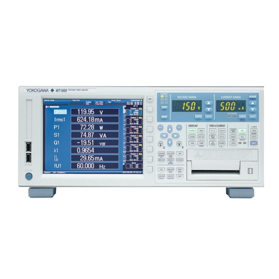
Chapter 1 Component Names and Functions Front Panel, Rear Panel, and Top Panel Front Panel Soft keys Use to select items on the soft key menus that appear during configuration. ESC key Use to clear soft key menus and pop-up menus. Setup and execution keys Handle Explanation →... - Page 18 1.1 Front Panel, Rear Panel, and Top Panel Rear Panel GP-IB connector Use to communicate with the WT1800 through the GP-IB interface. Explanation of the communication feature → communication interface user’s manual External start signal I/O connector • Use to perform master and slave Voltage input terminals synchronized measurement.→...
-
Page 19: Top Panel
1.1 Front Panel, Rear Panel, and Top Panel Top Panel Inlet holes → section 2.2 (There are also inlet holes on the bottom panel.) Vent holes → section 2.2 Handles Index Vent holes → section 2.2 IM WT1801-03EN... -
Page 20: Keys
The AUTO key turns off. EXT SENSOR Key Press EXT SENSOR to illuminate the EXT SENSOR key. While the WT1800 is in this state, press the current range’s ▲ and ▼ keys to select the external current sensor range that is used when the WT1800 measures the output from the current sensor. - Page 21 1.2 Keys SCALING Key Press this key to display a menu for setting the VT and CT ratios or the power coefficient for each input element. These ratios and the coefficient are used to convert the VT/CT output or the power derived from measuring the VT and CT outputs to the real voltage, current, and power of the item under measurement.
- Page 22 1.2 Keys UPDATE RATE Key Press this key to display a menu for selecting the period (data update interval) at which sampled data, which is used to produce numeric data (measured values such as voltage, current, and power), is acquired. HOLD Key Press HOLD to illuminate the HOLD key, stop data measurement and display operations per data update interval, and hold the numeric data display.
- Page 23 1.2 Keys Displaying the Measured Results NUMERIC Key Press this key to display numeric data. • When you are displaying numeric data, you can press ITEM, which is described later in this section, to display a menu for changing the displayed items. •...
- Page 24 On WT1800s that have six input elements installed, pressing SHIFT+ELEMENT (ALL) illuminates the ALL indicator. With the WT1800 in this state, each time you press ELEMENT, the input elements or wiring units of the displayed page switch between input elements and wiring units in the following order: 1, 2, 3, 4, 5, 6, Σ...
- Page 25 1.2 Keys Computation MEASURE Key Press this key to display a menu for configuring settings for user-defined functions, MAX hold, user- defined events, apparent and reactive power equations, corrected power equations, for selecting the phase difference display format and the sampling frequency, and for configuring settings for master and slave synchronized measurement.
- Page 26 SHIFT+SINGLE (CAL) Key Combination Press this key combination to execute zero-level compensation. When zero level compensation is executed, the WT1800 creates a zero input condition in its internal circuitry and sets the zero level to the level at that point.
-
Page 27: Local Key
LOCAL Key Press this key to switch from remote mode (in which the REMOTE indicator is illuminated) to local mode (in which front panel key operations are valid). This key is disabled when the WT1800 is in local lockout mode. -
Page 28: Screen Display
Displayed if a measurement function is not selected or if there is no numeric data. Error Displayed in cases such as when a measured value is outside of its determined range. Note The WT1800 LCD may have a few defective pixels. For details, see section 6.2, “Display.” 1-12 IM WT1801-03EN... -
Page 29: System Configuration
System Configuration Load Motor Power supply Current sensor Wind speed Torque Revolution Pyranometer sensor meter sensor Voltage Current etc. (Apply one of them) (Apply one of them) Motor evaluation Auxiliary input (option) (option) VOLTAGE Input ± CURRENT element ± Apply one set of signals External clock input Start and stop Master and slave... -
Page 30: Chapter 2 Making Preparations For Measurements
Do Not Remove the Case Do not remove the case from the instrument. Some parts of the instrument use high voltages and are extremely dangerous. For internal inspection and adjustment, contact your nearest YOKOGAWA dealer. Unplug If Abnormal Behavior Occurs If you notice smoke or unusual odors coming from the instrument, immediately turn off the power and unplug the power cord. - Page 31 2.1 Handling Precautions When Carrying the Instrument First, turn off the circuit under measurement and remove the measurement cables. Then, turn off the instrument and remove the power cord and any attached cables. As indicated in the following figure, use both hands to firmly hold the handles when carrying the instrument. In addition, if storage media is inserted in the instrument, be sure to remove the storage media before you move the instrument.
-
Page 32: Installing The Instrument
Installing the Instrument WARNING • Do not install the instrument outdoors or in locations subject to rain or water. • Install the instrument so that you can immediately remove the power cord if an abnormal or dangerous condition occurs. Installation Conditions Install the instrument in an indoors environment that meets the following conditions. - Page 33 2.2 Installing the Instrument Storage Location When storing the instrument, avoid the following places. • Where the relative humidity is greater than 80% • Where the level of mechanical vibration is high • In direct sunlight • Where there are corrosive or explosive gasses •...
-
Page 34: Connecting The Power Supply
• Confirm that the instrument’s power switch is off before you connect the power cord. • To prevent fire and electric shock, only use a power cord supplied by YOKOGAWA. • To avoid electric shock, be sure to ground the instrument. Connect the power cord to a three-prong power outlet with a protective earth terminal. -
Page 35: Turning The Power Switch On And Off
• Check that the correct voltage is coming to the power outlet. → Page 2-6 • Initialize the settings to their factory defaults by turning on the power switch while holding down the RESET key. If the instrument still does not work properly, contact your nearest YOKOGAWA dealer for repairs. Note •... - Page 36 If this message appears frequently, you need to replace the battery soon. Do not try to replace the battery yourself. Contact your nearest YOKOGAWA dealer to have the battery replaced.
-
Page 37: Precautions When Wiring The Circuit Under Measurement
Precautions When Wiring the Circuit under Measurement To prevent electric shock and damage to the instrument, follow the warnings below. WARNING • Ground the instrument before connecting measurement cables. The power cord that comes with the instrument is a three-prong cord. Insert the power cord into a grounded three- prong outlet. - Page 38 2.5 Precautions When Wiring the Circuit under Measurement • To make the protective features effective, before applying the voltage or current from the circuit under measurement, check that: • The power cord provided with the instrument is being used to connect to the power supply and that the instrument is grounded.
- Page 39 2.5 Precautions When Wiring the Circuit under Measurement CAUTION Use measurement cables with dielectric strengths and current capacities that are appropriate for the voltage or current being measured. Example: When making measurements on a current of 20 A, use copper wires that have a conductive cross-sectional area of 4 mm or greater.
-
Page 40: Assembling The Adapters For The Voltage Input Terminals
Terminals Assembling the 758931 Safety Terminal Adapter When connecting a measurement cable to a WT1800 voltage input terminal, use the included 758931 Safety Terminal Adapter or the 758923 Safety Terminal Adapter (sold separately). When using the 758931 Safety Terminal Adapter, assemble it according to the following procedure. - Page 41 2.6 Assembling the Adapters for the Voltage Input Terminals Explanation Wire the adapters that come with the WT1800 or the adapters and various sensors that are sold separately as shown below: Wiring When Measuring Voltage Voltage under measurement 758921 758917...
-
Page 42: Wiring For Accurate Measurements
Wiring for Accurate Measurements When you are wiring a single-phase device, there are the four patterns of terminal wiring positions shown in the following figures for wiring the voltage input and current input terminals. Depending on the terminal wiring positions, the effects of stray capacitance and the effects of the measured voltage and current amplitudes may become large. -
Page 43: Guide For Selecting The Method Used To Measure The Power
For example, if you replace the WT1000 (used in a three-phase, three-wire system) with the WT1800 and leave the wiring unchanged, the measured power of each element will be different between the WT1000 and the WT1800. Refer to this manual and re-wire the system correctly. -
Page 44: Wiring The Circuit Under Measurement For Direct Input
Unit: mm In the figures on the following pages, the WT1800’s input elements, voltage input terminals, and current input terminals are simplified as shown in the following figure. VOLTAGE... - Page 45 2.9 Wiring the Circuit under Measurement for Direct Input The wiring examples shown below are examples of the following wiring systems in which the specified input elements have been wired. To wire other input elements, substitute the numbers in the figures with the appropriate element numbers.
- Page 46 2.9 Wiring the Circuit under Measurement for Direct Input Wiring Example of a Three-Phase, Three-Wire System (3P3W) If six input elements are available, three three-phase, three-wire systems can be wired. ± LOAD SOURCE SOURCE ± LOAD ± ± ± ± ±...
-
Page 47: Wiring The Circuit Under Measurement When Using Current Sensors
2.10 Wiring the Circuit under Measurement When Using Current Sensors To prevent electric shock and damage to the instrument, follow the warnings given in section 2.5, “Precautions When Wiring the Circuit under Measurement.” If the maximum current of the circuit under measurement exceeds the maximum range of the input elements, you can measure the current of the circuit under measurement by connecting an external current sensor to the external current sensor input connector. -
Page 48: Index
Voltage input terminal ± LOAD External current sensor input connector In the figures on the following pages, the WT1800’s input elements, voltage input terminals, and external current sensor input connectors are simplified as shown in the following figure. VOLTAGE Voltage input terminal ±... - Page 49 2.10 Wiring the Circuit under Measurement When Using Current Sensors The following wiring examples are for connecting shunt-type current sensors. When connecting a clamp-type current sensor that outputs voltage, substitute shunt-type current sensors with clamp-type current sensors. Clamp-type current sensor Shunt-type current sensor that outputs voltage ±...
- Page 50 2.10 Wiring the Circuit under Measurement When Using Current Sensors Wiring Example of a Three-Phase, Three-Wire System (3P3W) with Shunt-Type Current Sensors SOURCE LOAD ± OUT L OUT H ± OUT L OUT H ± ± Input element 1 Input element 2 Wiring Example of a Three-Phase, Three-Wire System That Uses a Three-Voltage, Three-Current Method (3P3W;...
-
Page 51: Wiring The Circuit Under Measurement When Using Voltage And Current Transformers
2.11 Wiring the Circuit under Measurement When Using Voltage and Current Transformers This section explains how to wire measurement cables from external voltage transformers (VT) or current transformers (CT) to the voltage or current input terminals of input elements. Also refer to this section when wiring clamp-type current sensors that output current. - Page 52 2.11 Wiring the Circuit under Measurement When Using Voltage and Current Transformers Note • The thick lines on the wiring diagrams are the parts where the current flows. Use wires that are suitable for the current levels. • Make sure that you have the polarities correct when you make connections. If the polarity is reversed, the polarity of the measurement current will be reversed, and you will not be able to make correct measurements.
- Page 53 2.11 Wiring the Circuit under Measurement When Using Voltage and Current Transformers Wiring Example of a Three-Phase, Three-Wire System (3P3W) with VTs and CTs SOURCE LOAD L CT L CT ± ± ± ± Input element 1 Input element 2 Wiring Example of a Three-Phase, Three-Wire System That Uses a Three-Voltage, Three-Current Method (3P3W;...
-
Page 54: Loading Roll Paper Into The Built-In Printer (Option)
This section explains how to load roll paper into the optional built-in printer. Printer Roll Paper Only use roll paper specifically made for use with the WT1800. When you first use the printer, use the included roll paper. When you need a new supply of roll paper, contact your nearest YOKOGAWA dealer. - Page 55 1. Slide the lever to the right to make the printer unit 2. Insert your finger into the groove on the right side protrude from the WT1800. of the printer unit. Groove...
- Page 56 Close the cover until you hear a click. Cover Tray 7. Push the printer unit (push the area to the left of the lever on the front panel) back into the WT1800 until you hear a click. Push the printer unit until you Index This completes the procedure for loading the roll paper.
- Page 57 Press SHIFT+PRINT (MENU) to display the following menu. Feeds paper Each time that you press this soft key, the WT1800 feeds approximately 3 cm of the roll paper. Cutting Roll Paper After you load roll paper and close the cover or after you print measured data, to cut the roll paper, pull the paper up against the top of the cover.
-
Page 58: Chapter 3 Common Operations
Chapter 3 Common Operations Key Operation and Functions Key Operation How to Use Setup Menus That Appear When Keys Are Pressed The operation after you press a key varies depending on the key that you press. Numeric (4) Menu Measure Menu Line Filter Menu Numeric Form Menu Index... - Page 59 If you press RESET when you are using the cursor keys to set a value or select an item, the setting is reset to its default value (depending on the operating state of the WT1800, the setting may not be reset).
-
Page 60: Entering Values And Strings
Entering Values and Strings Entering Values Using the Cursor Keys to Enter Values Select the appropriate item using the soft keys, and change the value using the cursor keys and the SET key. This manual sometimes describes this operation simply as “using the cursor keys.” Note Some items that you can set using the cursor keys are reset to their default values when you press the RESET key. - Page 61 3.2 Entering Values and Strings Enter a character string from the history. Character insertion position Enter a preset character string. Move the character insertion position Deletes the previous character Deletes all characters Confirms the characters that you have entered Enter a character string from the history.
-
Page 62: Using Usb Keyboards And Mouse Devices
For USB keyboards that have been tested for compatibility, contact your nearest YOKOGAWA dealer. USB Ports for Peripherals Connect a USB keyboard to one of the USB ports for peripherals on the front panel of the WT1800. Connection Procedure Connect a USB keyboard directly to the WT1800 using a USB cable. You can connect or remove the USB cable regardless of whether the WT1800 is on or off (hot-plugging is supported). - Page 63 For USB mouse devices that have been tested for compatibility, contact your nearest YOKOGAWA dealer. • Some settings cannot be configured by a mouse without a wheel. USB Ports for Peripherals Connect a USB mouse to one of the USB ports for peripherals on the front panel of the WT1800. IM WT1801-03EN...
-
Page 64: Connection Procedure
To connect a USB mouse to the WT1800, use one of the USB ports for peripherals. You can connect or disconnect a USB mouse at any time regardless of whether the WT1800 is on or off (hot- plugging is supported). When the power is on, the mouse is detected approximately 6 seconds after it is connected, and the mouse pointer ( ) appears. - Page 65 3.3 Using USB Keyboards and Mouse Devices • Setup Menu Operations (Same as soft key operations) Selecting a Setup Menu Item Click the setup menu item that you want to select. If a selection menu appears after you select an item, click the selection menu item that you want to choose.
- Page 66 3.3 Using USB Keyboards and Mouse Devices • Selecting Check Boxes in Dialog Boxes Click the item that you want to select. A check mark appears next to the item that you selected. To clear an item’s check box, click it again. Click the item that you want to select.
-
Page 67: Setting The Menu And Message Languages
• Japanese • Chinese • German • Russian 1 This features covers firmware versions 2.01 or later of the WT1800. 2 This features covers firmware versions 2.21 or later of the WT1800. Note • Even if you set the menu or message language to a language other than English, some terms will be displayed in English. -
Page 68: Synchronizing The Clock
• If you select Manual, set the Date and Time values, and then select Set. • If you select SNTP, the WT1800 uses an SNTP server to set its date and time. This setting is valid when Ethernet communications have been established. For information on SNTP, see the user’s manual. - Page 69 3.5 Synchronizing the Clock Note • The WT1800 does not support Daylight Savings Time. To set the Daylight Savings Time, reset the time difference from Greenwich Mean Time. • Date and time settings are backed up using an internal lithium battery. They are retained even if the power is turned off.
-
Page 70: Initializing Settings
Note Only initialize the WT1800 if you are sure that it is okay for all of the settings to be returned to their initial values. You cannot undo an initialization. We recommend that you save the setup parameters before you initialize the WT1800. -
Page 71: Displaying Help
Displaying Help Displaying Help Press HELP to display the help screen. The table of contents and index appear in the left frame, and text appears in the right frame. Switching between Frames To switch to the frame that you want to control, use the left and right cursor keys. Moving Cursors and Scrolling •... -
Page 72: Chapter 4 Auxiliary I/O
CAUTION Only apply signals that meet the following specifications. Signals that do not meet the specifications, such as those with excessive voltage, may damage the WT1800. Torque Signal Input Connector (TORQUE) Apply a torque meter output signal—a DC voltage (analog) signal or pulse signal that is proportional to the motor’s torque—that meets the following specifications. - Page 73 4.1 Motor Torque Signal and Revolution Signal Input (TORQUE/SPEED; option) Revolution Signal Input Connector (SPEED) Apply a revolution sensor output signal—a DC voltage (analog) signal or pulse signal that is proportional to the motor’s rotating speed—that meets the following specifications. DC Voltage (Analog input) Item Specifications...
-
Page 74: Auxiliary Input (Aux1/Aux2; Option)
CAUTION Only apply signals that meet the following specifications. Signals that do not meet the specifications, such as those with excessive voltage, may damage the WT1800. Auxiliary Input Connectors (AUX1/AUX2) Apply a sensor output DC voltage signal (an analog signal) that meets the following specifications. -
Page 75: External Clock Input (Ext Clk In)
CAUTION Only apply signals that meet the following specifications. Signals that do not meet the specifications, such as those with excessive voltage, may damage the WT1800. External Clock Signal Input Connector Apply a clock signal that meets the following specifications to the external clock input connector (EXT CLK) on the rear panel. -
Page 76: External Start Signal I/O (Meas Start)
I/O connector (MEAS. START). Doing so may damage the WT1800. • If you have set the WT1800 as a slave unit or set External Sync to ON in high speed data capturing mode, only apply signals to the external start signal I/O connector that meet the following specifications. - Page 77 4.4 External Start Signal I/O (MEAS START) External Start Signal Output Circuit and Timing Chart +5 V +5 V 10 kΩ 100 Ω Start output signal Measurement start delay Measurement start Start output signal Output hold time External Start Signal Input Circuit and Timing Chart +5 V 100 Ω...
-
Page 78: Rgb Output (Rgb Out (Xga); Option)
RGB Output (RGB OUT (XGA); option) CAUTION • Only connect the WT1800 to a monitor after turning both the WT1800 and the monitor off. • Do not short the VIDEO OUT terminal or apply an external voltage to it. Doing so may damage the WT1800. -
Page 79: D/A Output And Remote Control (D/A Output; Option)
• Do not short or apply an external voltage to the D/A output terminal. Doing so may damage the WT1800. • When connecting the D/A output to another device, do not connect the wrong signal pin. Doing so may damage the WT1800 or the connected device. Item Specifications... -
Page 80: Remote Control
CAUTION Only apply voltages that are within the range of 0 V to 5 V to the remote control input pins. Do not short or apply external voltages to the output pins. Doing so may damage the WT1800. Item Specifications... - Page 81 If the width of the low pulse of the EXT SINGLE signal does not meet the conditions shown in the above figure, the signal may not be detected by the WT1800. Printing on the Built-In Printer (Option; the same functionality as pressing PRINT) Apply an EXT PRINT signal as shown in the following figure.
-
Page 82: Chapter 5 Troubleshooting, Maintenance, And Inspection
• If a message appears on the screen, see the appendix in the user’s manual, IM WT1801-02EN. • If servicing is necessary, or if the instrument does not operate properly even after you have attempted to deal with the problem according to the instructions in this section, contact your nearest YOKOGAWA dealer. Problems and Solutions Reference Section Nothing appears on the screen when you turn on the power. -
Page 83: Power Supply Fuse
Power Supply Fuse Because the power supply fuse used by this instrument is inside the case, you cannot replace it yourself. If you believe that the power supply fuse inside the case has blown, contact your nearest YOKOGAWA dealer. IM WT1801-03EN... -
Page 84: Recommended Replacement Parts
(items that wear out). The replacement period for expendable items varies depending on the conditions of use. Refer to the table below as a general guideline. Contact your nearest YOKOGAWA dealer to have parts replaced. -
Page 85: Chapter 6 Specifications
Chapter 6 Specifications Input Item Specifications Input terminal type Voltage Plug-in terminal (safety terminal) Current • Direct input: large binding post • External current sensor input: isolated BNC connector Input format Voltage Floating input through resistive voltage divider Current Floating input through shunt Measurement range Voltage Crest factor 3: 1.5 V, 3 V, 6 V, 10 V, 15 V, 30 V, 60 V, 100 V, 150 V, 300 V, 600 V, 1000 V... -
Page 86: Display
3) If the measurement mode display is set to Normal Mode (Trg), measurement takes place from when a trigger is detected over the data update interval. The following amount of time is required for the WT1800 to compute the measured data, process it for displaying, and so on, and become ready for the next trigger. -
Page 87: Displayed Items
Displayed Items Numeric Display Measurement Functions Determined for Each Input Element For details about how the measurement function values are computed and determined, see appendix 1. Item Symbols and Meanings Voltage (V) Urms: true rms value, Umn: rectified mean value calibrated to the rms value, Udc: simple average, Urmn: rectified mean value, Uac: AC component Current (A) Irms: true rms value, Imn: rectified mean value calibrated to the rms value, Idc: simple average, Irmn:... - Page 88 6.3 Displayed Items Measurement Functions (Σ Functions) Determined for Each Wiring Unit (ΣA, ΣB, and ΣC) For details about how Σ function values are computed and determined, see appendix 1. Item Symbols and Meanings Voltage (V) UrmsΣ: true rms value, UmnΣ: rectified mean value calibrated to the rms value, UdcΣ: simple average, UrmnΣ: rectified mean value, UacΣ: AC component Current (A) IrmsΣ: true rms value, ImnΣ: rectified mean value calibrated to the rms value, IdcΣ: simple average,...
- Page 89 6.3 Displayed Items Harmonic Measurement (Option) Measurement Functions Determined for Each Input Element Item Symbols and Meanings Voltage (V) U(k): rms voltage value of harmonic order k U: total rms voltage Current (A) I(k): rms current value of harmonic order k I: total rms current Active power (W) P(k): active power of harmonic order k...
- Page 90 6.3 Displayed Items Measurement Functions (Σ Functions) Determined for Each Wiring Unit (ΣA, ΣB, and ΣC) Item Symbols and Meanings Voltage (V) UΣ(1): rms voltage of harmonic order 1 UΣ: total rms voltage Current (A) IΣ(1): rms current of harmonic order 1 IΣ: total rms current Active power (W) PΣ(1): active power of harmonic order 1...
-
Page 91: Accuracy
Accuracy Voltage and Current Item Specifications Accuracy (at 6 months) Conditions Temperature: 23°C ± 5°C. Humidity: 30%RH to 75%RH. Input waveform: Sine wave. λ (power factor): 1. Common-mode voltage: 0 V. Crest factor: 3. Line filter: Off. Frequency filter: Set to 1 kHz. - Page 92 6.4 Accuracy Power Item Specifications Accuracy (at 6 months) Conditions Same as the conditions for the voltage and current accuracies Frequency Accuracy ±(reading error + measurement range error) ±(0.05% of reading + 0.1% of range) 0.1 Hz ≤ f < 10 Hz ±(0.3% of reading + 0.2% of range) 10 Hz ≤...
- Page 93 6.4 Accuracy Add the following values to the current and power accuracies of 5 A input elements. AC input signal: 0.006 × I % of reading DC input signal: 0.006 × I % of reading + 0.004 × I% of reading I is the current reading (A).
-
Page 94: Features
Features Measurement Features and Measurement Conditions Item Specifications Crest factor 300 for the minimum effective input 3 or 6 for the measurement range’s rated direct input Measurement period Period used to determine and compute measurement functions. • Except for watt hours (Wp) and DC ampere hours (q), the measurement period is set using the zero crossing points of the reference signal (synchronization source). - Page 95 6.5 Features Frequency Measurement Item Specifications Up to three of the voltage or current frequencies applied to an input element can be selected and measured. On models with the add-on frequency measurement option, the voltage and current frequencies of all input elements can be measured. Measurement method Reciprocal method Measurement range...
-
Page 96: Harmonic Measurement (Option)
Harmonic Measurement (Option) Item Specifications All installed elements Method PLL synchronization method (no external sampling clock) Frequency range The range for the fundamental frequency of the PLL source is 0.5 Hz to 2.6 kHz. PLL source • Select the voltage or current of each input element or an external clock. •... - Page 97 6.6 Harmonic Measurement (Option) Item Specifications Accuracy Add the following accuracy values to the normal measurement accuracy values. • When line filters are turned off Frequency Voltage Current Power 0.5 Hz ≤ f < 10 Hz 0.05% of reading 0.05% of reading 0.1% of reading + 0.25% of range + 0.25% of range...
-
Page 98: Motor Evaluation Function (Option)
Motor Evaluation Function (Option) Item Specifications Input terminal TORQUE, SPEED (A, B, Z) Input resistance Approx. 1 MΩ Input connector type Isolated BNC Analog Input (SPEED is being applied to terminal A.) Item Specifications Range 1 V, 2 V, 5 V, 10 V, 20 V Input range ±110% Line filter... -
Page 99: Auxiliary Input (Option)
Each rated value ±5 V FS (maximum of approx. ±7.5 V) Update interval Same as the WT1800 data update interval (if the waveform display is enabled and the trigger mode is set to Auto or Normal, the data update interval depends on the trigger operation) -
Page 100: High Speed Data Capturing (Option)
• Communication interface: GP-IB, Ethernet, or USB-PC Interface The captured data for each second is output together. Data capture start Data capturing starts after Start in the HS Settings menu is pressed or the WT1800 receives a communication command, and the trigger conditions are met. HS filter Off, 1 Hz to 1000 Hz (in steps of 1 Hz) 6.11 Computations and Event Feature... -
Page 101: Display
6.12 Display Numeric Display Item Specifications Number of Displayed Digits If the value is less than or equal to 60000: Five digits. (Display Resolution) If the value is greater than 60000: Four digits. Number of displayed items Select from 4, 8, 16, Matrix, ALL, Hrm List Single, Hrm List Dual, and Custom. Waveform Display Item Specifications... -
Page 102: Auxiliary I/O Section
6.15 Auxiliary I/O Section External Start Signal I/O Section To Apply the Master/Slave Synchronization Signal during Normal Measurement Item Specifications Connector type BNC connector (Same for both master and slave) I/O level (Same for both master and slave) Output logic Negative logic, falling edge (Applies to the master) Output hold time... -
Page 103: Computer Interface
6.16 Computer Interface GP-IB Interface Item Specifications Usable devices National Instruments Corporation • PCI-GPIB or PCI-GPIB+ • PCIe-GPIB or PCIe-GPIB+ • PCMCIA-GPIB or PCMCIA-GPIB+ • GPIB-USB-HS Use driver NI-488.2M Ver. 1.60 or later. Electrical and mechanical Complies with IEEE St’d 488-1978 (JIS C 1901-1987) specifications Functional specifications SH1, AH1, T6, L4, SR1, RL1, PP0, DC1, DT1, and C0... -
Page 104: Usb For Peripherals
Mouse devices that comply with USB HID Class Ver. 1.1 Power supply 5 V, 500 mA (for each port) You cannot connect devices whose maximum current consumptions exceed 100 mA to two different ports on the WT1800 at the same time. 6.18 Built-in Printer (Option) Item... -
Page 105: General Specifications
The same as the cable conditions listed above for emissions. Applies to products with CE marks. For information on other products, contact your nearest YOKOGAWA dealer. The overvoltage category (installation category) is a value used to define the transient overvoltage condition and includes the rated impulse withstand voltage. -
Page 106: External Dimensions
6.21 External Dimensions Unit: mm Rear view JIS rack mount dimensions Rack mounting surface 28.9 EIA rack mount dimensions 481.1 + 0.4 Rack mounting surface 28.9 Unless otherwise specified, tolerances are ±3% (however, tolerances are ±0.3 mm when below 10 mm). 6-22 IM WT1801-03EN... -
Page 107: Appendix
Appendix Appendix 1 Symbols and Determination of Measurement Functions Measurement Functions Used in Normal Measurement (Table 1/3) Methods of Computation and Determination Measurement Function For information about the symbols in the equations, see the notes at the end of page App-3. True rms value: Urms Urms Urmn... - Page 108 Appendix 1 Symbols and Determination of Measurement Functions (Table 2/3) Methods of Computation and Determination For information about the symbols in the equations, Measurement Function see the notes at the end of page App-3. Integration time Time from integration start to integration stop [h:m:s] Time When the watt-hour integration method for each polarity is Charge/Discharge...
- Page 109 Equation Type 3 for SΣ and QΣ can only be selected on models with the harmonic measurement option. • On the WT1800, S, Q, λ, and Φ are derived through the computation of the measured values of voltage, current, and active power (however, when Type 3 is selected, Q is calculated directly from the sampled data).
- Page 110 Appendix 1 Symbols and Determination of Measurement Functions Measurement Functions Used in Harmonic Measurement (Option) (Table 1/4) Methods of Computation and Determination Numbers and Characters in the Parentheses Measurement Function Total Value (Total) (No parentheses) (when k = 0) (when k = 1) (when k = 1 to max) U(k) = U(dc) =U...
- Page 111 Appendix 1 Symbols and Determination of Measurement Functions (Table 2/4) Methods of Computation and Determination The numbers and characters in the parentheses are dc (when k = 0) or k (when k = 1 to max). Measurement Function When the Denominator of the When the Denominator of the Distortion Factor Equation Is the Distortion Factor Equation Is the...
- Page 112 Appendix 1 Symbols and Determination of Measurement Functions (Table 3/4) Measurement Function Methods of Computation and Determination Three-Voltage, Three-Phase, Single-Phase, Three-Phase, Wiring system Three-Current Four-Wire (3P4W) Three-Wire (1P3W) Three-Wire (3P3W) Method (3V3A) UΣ [V] (U1 + U2) / 2 (U1 + U2 + U3) / 3 IΣ...
- Page 113 Appendix 1 Symbols and Determination of Measurement Functions Measurement Functions Used in Delta Computation (Option) Computed results are determined by substituting all of the sampled data in the table into the equations for voltage U and current I. The synchronization source used in delta computation is the same source as the source of the first input element (the input element with the smallest number) in the wiring unit that is subject to delta computation.
- Page 114 NULL: null value The WT1800 computes the torque pulse coefficient and torque pulse offset from torque values (the unit is N•m) at the upper and lower frequency limits. Normally use a scaling factor of 1. If you are using a unit other than N•m, set the unit conversion ratio.
- Page 115 Appendix 1 Symbols and Determination of Measurement Functions Measurement Methods of Computation and Determination Function – B Ur(1): real part of the fundamental voltage Uj(1): imaginary part of the fundamental voltage Electrical offset angle [°] – B Ir(1): real part of the fundamental current Ij(1): imaginary part of the fundamental current offset...
- Page 116 Appendix 1 Symbols and Determination of Measurement Functions Measurement Methods of Computation and Determination Function I[A] N−1 [i(n) ] True rms value HSFilter mean Rectified mean value calibrated to the rms value π N−1 × HSFilter [|i(n)|] rmean N−1 HSFilter [|i(n)|] Rectified mean value N−1 HSFilter [i(n)]...
- Page 117 Appendix 1 Symbols and Determination of Measurement Functions Measurement Methods of Computation and Determination Function ΣI[A] N−1 HSFilter [{i1(n) +i2(n) +i3(n) }/3] Three-phase, True rms value three-wire with three-voltage, mean Rectified mean value calibrated to the rms value three-current π N−1 method.
-
Page 118: Appendix 2 Power Basics (Power, Harmonics, And Ac Rlc Circuits)
Appendix 2 Power Basics (Power, harmonics, and AC RLC circuits) This section explains the basics of power, harmonics, and AC RLC circuits. Power Electrical energy can be converted into other forms of energy and used. For example, it can be converted into the heat in an electric heater, the torque in a motor, or the light in a fluorescent or mercury lamp. - Page 119 Appendix 2 Power Basics (Power, harmonics, and AC RLC circuits) To determine the mean value, the average is taken over 1 period of absolute values, because simply taking the average over 1 period of the sine wave results in a value of zero. With Imn as the mean value of the instantaneous current i (which is equal to Imsinωt): 2π...
- Page 120 Appendix 2 Power Basics (Power, harmonics, and AC RLC circuits) Three-Phase AC Wiring Generally three-phase AC power lines are connected in star wiring configurations or delta wiring configurations. Star wiring Delta wiring Vector Display of Three-Phase Alternating Current In typical three-phase AC power, the voltage of each phase is offset by 120°. The figure below expresses this offset using vectors.
- Page 121 Appendix 2 Power Basics (Power, harmonics, and AC RLC circuits) AC Power AC power cannot be determined as easily as DC power, because of the phase difference between the voltage and current caused by load. If the instantaneous voltage u = U sinωt and the instantaneous current i = Imsin(ωt –...
- Page 122 Appendix 2 Power Basics (Power, harmonics, and AC RLC circuits) Active Power and the Power Factor In alternating electrical current, not all of the power calculated by the product of voltage and current, UI, is consumed. The product of U and I is called the apparent power. It is expressed as S. The unit of apparent power is the volt-ampere (VA).
- Page 123 Appendix 2 Power Basics (Power, harmonics, and AC RLC circuits) Harmonics Harmonics refer to all sine waves whose frequency is an integer multiple of the fundamental wave (normally a 50 Hz or 60 Hz sinusoidal power line signal) except for the fundamental wave itself. The input currents that flow through the power rectification circuits, phase control circuits, and other circuits used in various kinds of electrical equipment generate harmonic currents and voltages in power lines.
- Page 124 Appendix 2 Power Basics (Power, harmonics, and AC RLC circuits) AC RLC Circuits Resistance The current i when an AC voltage whose instantaneous value u = U sinωt is applied to load resistance R [Ω] is expressed by the equation below. I denotes the maximum current.
- Page 125 Appendix 2 Power Basics (Power, harmonics, and AC RLC circuits) Series RLC Circuits The equations below express the voltage relationships when resistance R [Ω], inductance L [H], and capacitance C [F] are connected in series. U = (U + (U –...
-
Page 126: Appendix 3 How To Make Accurate Measurements
The input resistance of the current measurement circuit of the WT1800 is approximately 100 mΩ for the 5 A input terminals and approximately 2 mΩ for the 50 A input terminals. If the load resistance is 1 kΩ, the effect of e... - Page 127 Effects of Stray Capacitance The effects of stray capacitance on measurement accuracy can be minimized by connecting the WT1800 current input terminal to the side of the power supply (SOURCE) that is closest to its earth potential. The internal structure of the WT1800 is explained below.
-
Page 128: Appendix 4 Power Range
Appendix 4 Power Range The table below shows actual voltage and current range combinations and the power ranges that result from them. The values are for when the voltage and current ranges of each element are the same. The table shows the active power range (unit: W). The same ranges are set for apparent power (unit: VA) and reactive power (unit: var). - Page 129 Appendix 4 Power Range Current Voltage Range [V] Range 60.000 100.00 150.00 300.00 600.00 1000.0 10.000m 1200.00 mW 2.0000 W 3.0000 W 6.0000 W 12.0000 W 20.000 W 20.000m 2.4000 W 4.0000 W 6.0000 W 12.0000 W 24.000 W 40.000 W 50.000m 6.0000 W 10.0000 W...
- Page 130 Appendix 4 Power Range When the Crest Factor Is Set to CF6 Active Power Range of Each Element Current Voltage Range [V] Range 0.7500 1.5000 3.0000 5.0000 7.500 15.000 5.0000m 3.7500 mW 7.500 mW 15.000 mW 2.5000 mW 37.500 mW 75.00 mW 10.000m 7.500 mW...
- Page 131 Appendix 4 Power Range Current Voltage Range [V] Range 30.000 50.000 75.00 150.00 300.00 500.00 5.0000m 300.00 mW 500.00 mW 750.00 mW 1.5000 W 3.0000 W 5.0000 W 10.000m 600.00 mW 1000.00 mW 1.5000 W 3.0000 W 6.0000 W 10.0000 W 25.000m 1.5000 W 2.5000 W...
-
Page 132: Appendix 5 Setting The Measurement Period
I1 becomes the measurement period. By averaging the sampled data in this measurement period, the WT1800 computes the measured values for input element 1, such as U1, I1, and P1. Deciding Whether to Use Voltage or Current Input as the... - Page 133 (the center of the amplitude) on a rising (or falling) slope. The measurement period on the WT1800 is between the first rising (or falling) zero crossing and the last rising (or falling) zero crossing in the data update interval.
- Page 134 Also, turn on the frequency filter. The WT1800 reduces the effects of noise by using hysteresis when it detects zero crossings. If the synchronization source is distorted or harmonics and noise are superposed on the signal to a level exceeding this hysteresis, harmonic components will cause zero crossing detection to occur frequently, and the zero crossing of the fundamental frequency will not be detected stably.
- Page 135 1, 2, and 3 to the same signal. To facilitate this sort of configuration, the synchronization source setting on the WT1800 is linked to the Σ wiring unit of the wiring system (when independent input element configuration is turned off).
- Page 136 Appendix 5 Setting the Measurement Period Setting the Synchronization Period When Measuring the Efficiency of a Power Transformer • Power Transformer with Single-Phase Input and Single-Phase Output If you are using input elements 1 and 2 to measure a device that converts single-phase AC power to single-phase DC power, set the synchronization source of input elements 1 and 2 to the voltage (or current) on the AC power end.
- Page 137 Appendix 5 Setting the Measurement Period AC power U2 and I2 DC power U1 and I1 AC power U3 and I3 Power transformer Synchronization Source Setup Example Input element 1 Input element 2 U2 (or I2, U3, or I3) Input element 3 •...
-
Page 138: Appendix 6 User-Defined Function Operands
Appendix 6 User-Defined Function Operands The following is a list of operands that can be used in user-defined functions. Measurement Functions Used in Normal Measurement Measurement Function User-Defined Function Parameter in ( ) Element Wiring Unit Example E1 to E6 E7 to E9 Urms URMS( ) - Page 139 Appendix 6 User-Defined Function Operands Efficiency Measurement Function User-Defined Function Parameter in ( ) Element Wiring Unit Example E1 to E6 E7 to E9 η1 ETA1( ) ETA1( ) None or space η2 ETA2( ) ETA2( ) None or space η3 ETA3( ) ETA3( )
- Page 140 Appendix 6 User-Defined Function Operands MAX Hold Measurement Function User-Defined Function Parameter in ( ) Element Wiring Unit Example E1 to E6 E7 to E9 Rms voltage URMSMAX( ) URMSMAX(E1) Voltage mean UMEANMAX( ) UMEANMAX(E1) Voltage simple average UDCMAX( ) UDCMAX(E1) Voltage rectified mean URMEANMAX( )
- Page 141 Appendix 6 User-Defined Function Operands Delta Computation Option Measurement Function User-Defined Function Parameter in ( ) Element Wiring Unit Example E1 to E6 E7 to E9 ΔU1( ) DELTAU1( ) DELTAU1(E7) ΔU2( ) DELTAU2( ) DELTAU2(E7) ΔU3( ) DELTAU3( ) DELTAU3(E7) ΔUΣ( ) DELTAUSIG( )
- Page 142 Appendix 6 User-Defined Function Operands Harmonic Measurement Option or Simultaneous Dual Harmonic Measurement Option Measurement User-Defined Function Left Parameter in ( , ) Right Parameter in ( , ) Function or Parameter in ( ) Element Wiring Unit Harmonic Order Total Fundamental Harmonics...
-
Page 143: Appendix 7 Usb Keyboard Key Assignments
Appendix 7 USB Keyboard Key Assignments 104 Keyboard (US) When the Ctrl Key Is Held Down on the When the Soft Keyboard Is Displayed Other USB Keyboard on the WT1800 When the WT1800 +Shift on the When the WT1800 Shift Is On USB Keyboard... - Page 144 Appendix 7 USB Keyboard Key Assignments When the Ctrl Key Is Held Down on the When the Soft Keyboard Is Displayed Other USB Keyboard on the WT1800 When the WT1800 +Shift on the When the WT1800 Shift Is On USB Keyboard...
- Page 145 109 Keyboard (Japanese) When the Ctrl Key Is Held Down on When the Soft Keyboard Is Displayed on Other the USB Keyboard the WT1800 When the WT1800 +Shift on the When the WT1800 Shift Is On USB Keyboard Shift Is On...
- Page 146 Appendix 7 USB Keyboard Key Assignments When the Ctrl Key Is Held Down on When the Soft Keyboard Is Displayed on Other the USB Keyboard the WT1800 When the WT1800 +Shift on the When the WT1800 Shift Is On USB Keyboard Shift Is On...
- Page 147 Appendix 8 List of Initial Settings and Numeric Data Display Order Factory Default Settings (Example for a model with six input elements installed) The default settings vary depending on the number of installed input elements and what options are installed. Item Setting RANGE...
- Page 148 Appendix 8 List of Initial Settings and Numeric Data Display Order Item Setting User-Defined Event On/Off Event Name True False Expression Event No.1 True False URMS(E1) > 0.00000 Event No.2 True False IRMS(E1) > 0.00000 Event No.3 True False EV1() & EV2() Event No.4 True False...
- Page 149 Appendix 8 List of Initial Settings and Numeric Data Display Order Item Setting Electrical Angle Measurement Electrical Angle Offset Offset Value 0.00 Auto Enter Target AUX SET (Available on models with the auxiliary input option) Aux Name AUX1 AUX2 Scaling 1.0000 1.0000 Unit...
- Page 150 Setting FORM (Wave) Format Single Time/div Trigger Settings Mode Auto (This features covers firmware versions 2.21 or before of the WT1800.) Off (This features covers firmware versions 2.22 or later of the WT1800.) Source Slope Rise Level 0.0% Display Setting...
- Page 151 Appendix 8 List of Initial Settings and Numeric Data Display Order Item Setting FORM (High speed data capturing; displayed on models with the high speed data capturing option) Capt. Count Infinite Control Settings U/I Measuring Mode Setting Each U1 to I6 HS Filter Cutoff 100Hz...
-
Page 152: Appendix 8 List Of Initial Settings And Numeric Data Display Order
Appendix 8 List of Initial Settings and Numeric Data Display Order Item Setting CURSOR (Wave) Wave Cursor Wave C1+ Trace Wave C2x Trace Cursor Path Wave C1+ Position Wave C2x Position Linkage CURSOR (Trend) Trend Cursor Trend C1+ Trace Trend C2x Trace Trend C1+ Position Trend C2x Position 1440... - Page 153 Test Item Memory 1 This setting is not affected when the WT1800 is initialized (when you press UTILITY and then the Initialize Settings soft key). 2 Items that are not loaded when a setup parameter file is loaded (FILE-Load Setup)
- Page 154 Appendix 8 List of Initial Settings and Numeric Data Display Order Numeric Data Display Order (Example for a Model with Six Input Elements Installed) If you reset the order of the numeric data using the Element Origin setting, the data of each measurement function is displayed in the order indicated in the table below.
- Page 155 Appendix 8 List of Initial Settings and Numeric Data Display Order All Items Display Page Urms Urms Irms Time η1 ΔU1 U(k) Uhdf(k) Uthd K-factor rmsI η2 ΔU2 I(k) Ihdf(k) Ithd η3 ΔU3 P(k) Phdf(k) Pthd Urmn Irmn η4 ΔUΣ S(k) Z(k) Uthf...
-
Page 156: Appendix 9 Limitations On Modifying Settings And Operations
Appendix 9 Limitations on Modifying Settings and Operations During integration, storage, and auto printing, there are measurement conditions and computations whose settings you cannot change and features that you cannot execute. Operation (Changing settings or executing features) Integration Status Storage State Auto Print Start or Stop,... - Page 157 Appendix 9 Limitations on Modifying Settings and Operations Operation (Changing settings or executing features) Integration Status Storage State Auto Print Start or Stop, Start or Stop Comp or Ready Timeup, or Ready Error Error Computation S Formula S, Q Formula Pc Formula Sampling Frequency Phase...
- Page 158 Appendix 10 Limitations on the Features during High Speed Data Capturing During high speed data capturing, there are measurement conditions and computations whose settings you cannot change and features that you cannot execute. Item Operation 1, 2 High Speed Data Capturing Capture Count 1, 2 Optimize Count...
-
Page 159: Appendix 10 Limitations On The Features During High Speed Data Capturing
8 You cannot select Auto. When the sampling frequency has been set to Auto for normal measurement and you switch to high speed data capturing, the WT1800 operates under the Clock C setting. 9 You can print a screen image. You cannot print numeric data lists. -
Page 160: Appendix 11 Block Diagram
Appendix 11 Block Diagram Block Diagram Input elements 2 to 6 Input element 1 Voltage input circuit 8.4-inch LCD Voltage measurement input circuit Line filter Frequency measurement Isolator input circuit Zero-crossing ± detection Frequency filter RGB output Input peak detection circuit Peak (option) detection... - Page 161 Appendix 11 Block Diagram The voltage signal that is applied to the voltage A/D converter and current A/D converter is converted to digital values at an interval of approximately 0.5 μ s. These digital values are isolated by the isolator and passed to the DSP.
Need help?
Do you have a question about the WT1800 and is the answer not in the manual?
Questions and answers