
Subscribe to Our Youtube Channel
Related Manuals for YOKOGAWA WT332


Summary of Contents for YOKOGAWA WT332
- Page 1 User’s Manual WT310/WT310HC/WT332/WT333 Digital Power Meter Getting Started Guide IM WT310-02EN 3rd Edition...
- Page 2 Product Registration Thank you for purchasing YOKOGAWA products. YOKOGAWA provides registered users with a variety of information and services. Please allow us to serve you best by completing the product registration form accessible from our website. http://tmi.yokogawa.com/ PIM 103-04E...
- Page 3 Thank you for purchasing the WT310, WT310HC, WT332, or WT333 Digital Power Meter (hereinafter, “WT300 series” will refer to all of these products). The WT300 series is a power measurement instrument that can measure parameters such as voltage, current, and power.
-
Page 4: Checking The Contents Of The Package
Unpack the box and check the contents before operating the instrument. If the wrong items have been delivered, if items are missing, or if there is a problem with the appearance of the items, contact your nearest YOKOGAWA dealer. WT310/WT310HC/WT332/WT333 (WT300 series) Check that the product that you received is what you ordered by referring to the model name and suffix code given on the name plate on the left side panel. - Page 5 WT310: One set with one hexagonal socket wrench WT310HC: One set with one hexagonal socket wrench WT332: Two sets with one hexagonal socket wrench WT333: Three sets with one hexagonal socket wrench For instructions on how to assemble the 758931, see section 2.6.
- Page 6 PDFs of the WT300 Series User’s Manuals These manuals are in the Manuals folder. English File Name Manual Title Manual No. User's Manual.pdf WT310/WT310HC/WT332/WT333 Digital Power Meter IM WT310-01EN User's Manual Getting Started Guide.pdf WT310/WT310HC/WT332/WT333 Digital Power Meter IM WT310-02EN Getting Started Guide Communication Interface.pdf...
- Page 7 Optional Accessories (Sold separately) The following optional accessories are available for purchase separately. Use the accessories specified in this manual. Moreover, use the accessories of this product only with Yokogawa products that specify them as accessories. For information about ordering accessories, contact your nearest YOKOGAWA dealer.
-
Page 8: Safety Precautions
The general safety precautions described herein must be observed during all phases of operation. If the instrument is used in a manner not specified in this manual, the protection provided by the instrument may be impaired. YOKOGAWA assumes no liability for the customer’s failure to comply with these requirements. - Page 9 To prevent the possibility of electric shock or fire, be sure to use the power cord supplied by YOKOGAWA. The main power plug must be plugged into an outlet with a protective earth terminal. Do not invalidate this protection by using an extension cord without protective earth grounding.
- Page 10 The amount of time that power remains in the item under measurement varies depending on the item. Accessories Use the accessories specified in this manual. Moreover, use the accessories of this product only with Yokogawa products that specify them as accessories. Do not use faulty accessories. CAUTION Operating Environment Limitations This product is a Class A (for industrial environments) product.
- Page 11 Authorized Representative in the EEA Yokogawa Europe B.V. is the authorized representative of Yokogawa Meters & Instruments Corporation for this product in the EEA. To contact Yokogawa Europe B.V., see the separate list of worldwide contacts, PIM 113-01Z2. IM WT310-02EN...
-
Page 12: Symbols And Notation Used In This Manual
Symbols and Notation Used in This Manual Units k: Denotes 1000. Example: 100 kHz (frequency) K: Denotes 1024. Example: 720 KB (file size) Notes The notes and cautions in this manual are categorized using the following symbols. Improper handling or use can lead to injury to the user or damage to the instrument. - Page 13 Symbols and Notation Used in This Manual Symbols and Conventions Used in Procedural Explanations The contents of the procedural explanations are indicated using the following symbols. This mark appears on the right side of the page to indicate features and settings that can be operated and configured using the WTViewerFreePlus application software, which comes with the instrument.
-
Page 14: Workflow
Workflow The figure below is provided to familiarize the first-time user with the workflow of WT300 series operation. For a description of an item, see the relevant section or chapter. In addition to the sections and chapters that are referenced in the figure below, this manual also contains safety precautions for handling and wiring the instrument. -
Page 15: Table Of Contents
Operating the WT300 series Setting the Measurement Ranges ..................4-1 Configuring the Wiring System Settings (Only on the WT332/WT333) ......4-4 Displaying the Voltage, Current, and Active Power on the WT310/WT310HC ....4-5 Displaying Voltages, Currents, and Active Powers on the WT332/WT333 ...... 4-6... - Page 16 Contents Chapter 6 Troubleshooting, Maintenance, and Inspection Troubleshooting ........................ 6-1 Error Code Descriptions and Corrective Actions .............. 6-2 Recommended Part Replacement ................... 6-3 Calibration and Adjustment ....................6-4 Chapter 7 Specifications Input ..........................7-1 Measurement Items ......................7-4 Accuracy ........................... 7-5 Functions ..........................
-
Page 17: Component Names And Functions
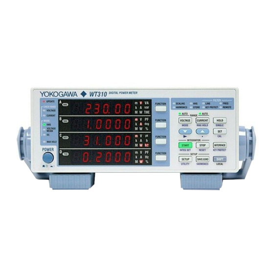
Chapter 1 Component Names and Functions Front Panel, Rear Panel, and Top Panel WT310/WT310HC Front Panel Function and unit indicators 7-segment LED → section 1.2 display Keys → section 1.2 → section 1.4 Handle Used to carry the WT310/WT310HC → section 2.1 Power switch →... - Page 18 1.1 Front Panel, Rear Panel, and Top Panel Top Panel Inlet holes → section 2.2 (There are also inlet holes on the bottom panel.) Vent holes → section 2.2 IM WT310-02EN...
- Page 19 Keys → section 1.2 → section 1.4 Power switch → section 2.4 Handle Used to carry the WT332/WT333 → section 2.1 Rear Panel Current input terminal For connecting current measurement cables → sections 2.8, 2.9, and 2.11 GP-IB or RS-232 connector...
- Page 20 1.1 Front Panel, Rear Panel, and Top Panel Top Panel Inlet holes → section 2.2 (There are also inlet holes on the bottom panel.) Vent holes → section 2.2 IM WT310-02EN...
-
Page 21: Displayed Items
Displayed Items WT310/WT310HC Data update indicator (UPDATE) Blinks when measurement data is being updated. Auto range monitor (CHECK RANGE) Lights when an input signal meets the conditions for auto range switching Measurement mode indicator (MODE) Indicates the voltage and current measurement modes MAX HOLD indicator (MAX HOLD) Lights when MAX HOLD is enabled 7-segment LED display... - Page 22 When you start storage, this indicator blinks at the pace at which storage is taking place. Key protection indicator (KEY PROTECT) Lights when the keys are locked Remote indicator (REMOTE) Lights when the WT332/WT333 is in remote mode IM WT310-02EN...
-
Page 23: Digital Numbers And Characters
Digital Numbers and Characters Because this instrument uses a 7-segment LED display, numbers, letters, and mathematical symbols are displayed using special characters in the manner shown below. Some of the characters shown below are not used by this instrument. ^ (exponentiation) Lowercase c –... -
Page 24: Keys
Keys Switching the Display FUNCTION Key Choose which function to display. ELEMENT Key (Only on the WT332/WT333) Choose which input element to display. The indicator of the selected element lights. WT310/WT310HC WT332/WT333 Measurement Range and Mode VOLTAGE Key Displays the voltage range setting menu. The AUTO indicator lights when the range is set to AUTO. - Page 25 1.4 Keys Display Hold/MAX Hold SHIFT+CURRENT (MAX HOLD) Key Turns the MAX hold feature on and off. When the MAX hold feature is on, the MAX HOLD indicator lights. HOLD Key Switches from updating the display after each data update interval to stopping the series of display operations and holding the display of the numeric data.
- Page 26 1.4 Keys Integrated Power (Watt hour) START Key Starts integration STOP Key Stops integration SHIFT+START (INTEG SET) Key Displays a menu for setting the integration mode, timer, and rated integration time SHIFT+STOP Key (RESET) Resets the integrated value and the elapsed integration time. Communication Interface INTERFACE Key Displays the communication interface setting menu and connection information...
- Page 27 1.4 Keys Other Features SETUP Key Set the measurement synchronization source, input filter, scaling, external current sensor input, averaging, computation, data update interval, etc. SAVE/LOAD Key Save or load setup data. SHIFT+SETUP (UTILITY) Key Displays a menu for displaying system information (model information, suffix code, instrument number, and firmware version), initializing settings, setting the number of displayed digits, performing self-tests, and configuring crest factor, storage, network, and D/A output settings.
-
Page 28: Auto Range, Overrange, And Error Indications During Measurement
If a computed value cannot be displayed using the specified decimal place or unit, the following indication appears. Auto Range Monitor Indications When an input signal meets the conditions for auto range switching, an indicator lights. WT310/WT310HC WT332/WT333 Colors and Meanings of Auto Range Monitor Indicators Color Description Peak overrange... - Page 29 1.5 Auto Range, Overrange, and Error Indications During Measurement Error Displayed in cases such as when a measured value is outside of its determined range. Index 1-13 IM WT310-02EN...
-
Page 30: System Configuration
System Configuration Load Power Supply Current sensor (optional) Voltage Current (Apply one of them.) (Apply one of them.) Remote control signal WT300 series (optional) Integration start Internal memory Integration stop Numeric data storage Hold/ single USB interface/ GP-IB interface RS-232 interface D/A output (option) Ethernet interface (optional) Measured values... -
Page 31: Chapter 2 Making Preparations For Measurements
Do Not Remove the Case Do not remove the case from the instrument. Some parts of the instrument use high voltages and are extremely dangerous. For internal inspection and adjustment, contact your nearest YOKOGAWA dealer. Unplug If Abnormal Behavior Occurs If you notice smoke or unusual odors coming from the instrument, immediately turn off the power and unplug the power cord. - Page 32 When carrying the instrument, use the handle as shown in the following figure, or use both hands to hold the instrument firmly. WT310/WT310HC WT332/WT333 When Cleaning the Instrument When cleaning the case or the operation panel, turn off the circuit under measurement and the instrument and remove the instrument’s power cord from the outlet.
-
Page 33: Installing The Instrument
Installing the Instrument Installation Conditions WARNING • Do not install the instrument outdoors or in locations subject to rain or water. • Install the instrument so that you can immediately remove the power cord if an abnormal or dangerous condition occurs. Install the instrument in an indoors environment that meets the following conditions. - Page 34 WT310/WT310HC when the handle is in stop position 2 or 4.) Rotating base Pull this out approximately 2 mm to 3 mm, and rotate the handle. • WT332/WT333 Movable legs WARNING • When adjusting the WT310/WT310HC handle, be careful not to injure your hand with the edges of the handle.
- Page 35 751533-J2 For JIS single mount Rack mount kit 751534-E2 For EIA dual mount Rack mount kit 751534-J2 For JIS dual mount • For the WT332/WT333 Item Model Note Rack mount kit 751533-E3 For EIA single mount Rack mount kit 751533-J3...
-
Page 36: Connecting The Power Supply
• Connect the power cord after checking that the power switch of the instrument is turned OFF. • To prevent fire and electric shock, only use a power cord supplied by YOKOGAWA. • To avoid electric shock, be sure to ground the instrument. Connect the power cord to a three-prong power outlet with a protective earth terminal. -
Page 37: Turning The Power Switch On And Off
For details about initializing the settings, see section 3.3, “Initializing Settings.” • If the instrument still does not work properly, contact your nearest YOKOGAWA dealer for repairs. • If an error code is displayed, see section 6.2, “Error Code Descriptions and Corrective Actions,” and take the appropriate actions. - Page 38 (see section 6.2, “Error Code Descriptions and Corrective Actions”). If this message appears frequently, you need to replace the battery soon. Do not try to replace the battery yourself. Contact your nearest YOKOGAWA dealer to have the battery replaced. Power-on Messages Power on All the LEDs light.
-
Page 39: Precautions When Wiring The Circuit Under Measurement
Precautions When Wiring the Circuit under Measurement To prevent electric shock and damage to the instrument, follow the warnings below. WARNING • Ground the instrument before connecting measurement cables. The power cord that comes with the instrument is a three-prong cord. Insert the power cord into a grounded three- prong outlet. - Page 40 Peak value of 2.8 kV or rms value of 2 kV, whichever is less. Current input Direct input • WT310 and WT332/WT333 When the crest factor is 3: 0.5 A to 20 A When the crest factor is 6: 0.25 A to 10 A Peak value of 450 A or rms value of 300 A, whichever is less.
- Page 41 Peak value of 1.5 kV or rms value of 1.0 kV, whichever is less. Current input Direct input • WT310 and WT332/WT333 When the crest factor is 3: 0.5 A to 20 A When the crest factor is 6: 0.25 A to 10 A Peak value of 100 A or rms value of 30 A, whichever is less.
-
Page 42: Assembling The Adapters For The Voltage Input Terminals
Assembling the Adapters for the Voltage Input Terminals When connecting a measurement cable to a WT300 series voltage input terminal, use the included 758931 Safety Terminal Adapter or the 758923 Safety Terminal Adapter (sold separately). 758931 Safety Terminal Adapter Cover Internal insulator Plug When using the 758931 Safety Terminal Adapter, assemble it according to the following procedure. - Page 43 758921 758917 WT310/WT310HC Voltage input terminals 758922 758923 758929 WT332/WT333 Voltage input terminals 758931 Wiring to a Current Input Terminal Use the clamp-on probes (sold separately) as shown below. Current under measurement Index When you are connecting to the 96030, 96031, 96030 or 758924, remove the terminal sleeves.
-
Page 44: Wiring For Accurately Measuring A Single-Phase Device
Wiring for Accurately Measuring a Single- phase Device When you are wiring a single-phase device, there are the four patterns of terminal wiring positions shown in the following figures for wiring the voltage input and current input terminals. Depending on the terminal wiring positions, the effects of stray capacitance and the effects of the measured voltage and current amplitudes may become large. -
Page 45: Guide For Selecting The Method Used To Measure The Power
Voltage transformer (VT) → section 2.11 Current Measurement Methods When the Voltage Is 600 V or Less When the Current When the Current WT310/WT332/WT333 When the Voltage Is 20 A or Less Exceeds 20 A Product Exceeds 600 V name... -
Page 46: Wiring The Circuit Under Measurement For Direct Input
Voltage input terminals 758931 WT310/WT310HC WT332/WT333 Current Input Terminals The terminals are binding posts, and the screws are M6. Either wind a wire around a screw or pass a crimped terminal through the screw axis, and then tighten firmly with the terminal knob. - Page 47 2.9 Wiring the Circuit under Measurement for Direct Input Connecting to a Round Crimped Terminal To connect a cable with a round crimped terminal to a current input terminal, follow the procedure below. Note that once the stopper pressed into the knob is removed, it will easily come off if it is used again.
- Page 48 2.9 Wiring the Circuit under Measurement for Direct Input Connecting to the WT310/WT310HC In the wiring examples that follow, the WT310/WT310HC input elements, voltage input terminals, and current input terminals are simplified as shown in the following figure. Input element Current input Voltage input terminals...
- Page 49 2.9 Wiring the Circuit under Measurement for Direct Input Example Wiring Procedure This example will explain the procedure that you should use to configure the wiring when using the WT310 to measure the power of a single-phase, two-wire DUT. The procedure is the same when measuring using the WT310HC.
- Page 50 2.9 Wiring the Circuit under Measurement for Direct Input Strip the insulation of the power cable that you cut, and attach round crimped terminals if necessary. Connect the power cable to the WT310 in the following ways. • Power-source-side cable: Connect to the ± current input terminal. •...
- Page 51 2.9 Wiring the Circuit under Measurement for Direct Input Attach 758931 Safety Terminal Adapters to the voltage measurement cables. For details on how to assemble and attach the safety terminal adapters, see section 2.5. You can avoid wiring mistakes by connecting a red adapter to the high-voltage cable and a black adapter to the low-voltage cable.
- Page 52 2.9 Wiring the Circuit under Measurement for Direct Input You can also connect to the circuit under measurement by placing a terminal block near the WT310 and connecting the power cables and voltage measurement cables to the terminal block. Terminal block 2-22 IM WT310-02EN...
- Page 53 2.9 Wiring the Circuit under Measurement for Direct Input Connecting to the WT332/WT333 In the wiring examples that follow, the WT332/WT333 input elements, voltage input terminals, and current input terminals are simplified as shown in the following figure. V: VOLTAGE terminal C: CURRENT terminal ±...
- Page 54 2.9 Wiring the Circuit under Measurement for Direct Input Wiring Example of a Single-Phase, Three-Wire System (1P3W) The wiring is connected to input elements 1 and 3. LOAD SOURCE ± ± ± ± LOAD SOURCE ± ± ± ± Element 1 Element 3 (V1, A1) (V3, A3)
- Page 55 2.9 Wiring the Circuit under Measurement for Direct Input Wiring Example with the Three-Voltage, Three-Current Method (3V3A) Applies to the WT333. The wiring is connected to input elements 1, 2, and 3. ± SOURCE LOAD ± SOURCE LOAD ± ± ±...
- Page 56 Generally, it is easier to follow the wiring diagram if you wire to the current input terminals first and then to the voltage input terminals. In this example as well, we will wire to the WT332/WT333 current input terminals first and then to the voltage input terminals.
- Page 57 ± Note Why You Do Not Have to Connect the WT332/WT333 Current Input Terminals to the S-Phase Cable In a three-phase, three-wire wiring system, there is no neutral line. This means that either the R, S, or T phase is treated as a virtual neutral line when power is measured. In this example, the S-phase cable is treated as the virtual neutral line.
- Page 58 2.9 Wiring the Circuit under Measurement for Direct Input Wiring to the Voltage Input Terminals Connect the voltage input terminals in parallel with the DUT. Using phase S as the reference, measure the line voltage between phase R and phase S and between phase T and phase S.
- Page 59 2.9 Wiring the Circuit under Measurement for Direct Input Connect the safety terminal adapters to the WT332/WT333 voltage input terminals. • Red R-phase adapter: Connect to the VOLTAGE voltage input terminal of element 1. • Red T-phase adapter: Connect to the VOLTAGE voltage input terminal of element 3.
- Page 60 2.9 Wiring the Circuit under Measurement for Direct Input You can also connect to the circuit under measurement by placing a terminal block near the WT332/ WT333 and connecting the power cables and voltage measurement cables to the terminal block.
- Page 61 If the maximum current of the circuit under measurement exceeds the maximum range of the input elements, you can measure the current of the circuit under measurement by connecting an external current sensor to the external current sensor input terminal. • WT310 and WT332/WT333 When the maximum current exceeds 20 Arms • WT310HC...
- Page 62 2.10 Wiring the Circuit under Measurement When Using Current Sensors CAUTION The thick lines on the wiring diagrams are the parts where the current flows. Use wires that are suitable for the current levels. Note • Make sure that you have the polarities correct when you make connections. If the polarity is reversed, the polarity of the measurement current will be reversed, and you will not be able to make correct measurements.
-
Page 63: 2.10 Wiring The Circuit Under Measurement When Using Current Sensors
WT300 series Voltage input terminals ± LOAD External current sensor input terminal Connecting the 96001 Clamp-on Probe When using the Yokogawa 96001 Clamp-on Probe, use the 758924 Conversion Adapter (optional accessory). 96001 (voltage output type) WT310/WT310HC 758924 EXT input terminal WT332/WT333... - Page 64 2.10 Wiring the Circuit under Measurement When Using Current Sensors Connecting to the WT310/WT310HC In the wiring examples that follow, the WT310/WT310HC input elements, voltage input terminals, and current input terminals are simplified as shown in the following figure. Voltage input WT310/WT310HC terminals External current sensor...
- Page 65 2.10 Wiring the Circuit under Measurement When Using Current Sensors Connecting to the WT332/WT333 In the wiring examples that follow, the WT332/WT333 input elements, voltage input terminals, and current input terminals are simplified as shown in the following figure. ±...
- Page 66 2.10 Wiring the Circuit under Measurement When Using Current Sensors Wiring Example of a Single-Phase, Three-Wire System (1P3W) with Shunt-Type Current Sensors The wiring is connected to input elements 1 and 3. SOURCE LOAD OUT H OUT L OUT H OUT L ±...
- Page 67 2.10 Wiring the Circuit under Measurement When Using Current Sensors Wiring Example with the Three-Voltage, Three-Current Method (3V3A) and Shunt-Type Current Sensors Model: Applies to the WT333. The wiring is connected to input elements 1, 2, and 3. SOURCE LOAD OUT H OUT L OUT H...
-
Page 68: Wiring The Circuit Under Measurement When Using A Voltage Or Current Transformer
CT or a clamp-type sensor that outputs current to the current input terminal. • WT310 and WT332/WT333 When the maximum current exceeds 20 Arms • WT310HC... - Page 69 To measure the apparent power and power factor more accurately on an unbalanced three-phase circuit, we recommend that you use the three-voltage, three-current method (3V3A). When using the Yokogawa 751552 Clamp-on Probe, use the 758917 Measurement Lead and the 758921 Fork Terminal Adapter Set (optional accessory).
- Page 70 2.11 Wiring the Circuit under Measurement When Using a Voltage or Current Transformer Connecting to the WT310/WT310HC In the wiring examples that follow, the WT310/WT310HC input elements, voltage input terminals, and current input terminals are simplified as shown in the following figure. Input element Current input Voltage input...
- Page 71 2.11 Wiring the Circuit under Measurement When Using a Voltage or Current Transformer Connecting to the WT332/WT333 In the wiring examples that follow, the WT332/WT333 input elements, voltage input terminals, and current input terminals are simplified as shown in the following figure.
- Page 72 2.11 Wiring the Circuit under Measurement When Using a Voltage or Current Transformer Wiring Example of Single-Phase, Two-Wire Systems (1P2W) with a VT and CT The following wiring example shows how to configure the wiring to connect to input element 1. To configure the wiring for other input elements, substitute the numbers in the figures with the appropriate element numbers.
- Page 73 2.11 Wiring the Circuit under Measurement When Using a Voltage or Current Transformer Wiring Example of a Three-Phase, Four-Wire System (3P4W) with VTs and CTs Model: Applies to the WT333. The wiring is connected to input elements 1, 2, and 3. SOURCE LOAD L CT...
-
Page 74: Connecting To A Pc Via Usb (Installing Wtviewerfreeplus)
WT300 series settings from the PC. In addition, you can use WTViewerFreePlus, which is a software application supplied with the WT300 series, to save measured data to the PC and change the WT300 series settings, without having to create original communication control programs. PC monitor WT332/WT333 WT310/WT310HC Saved data Setting changes The WT300 series can be connected to a PC using the following communication interfaces. - Page 75 Click Allow or Yes to continue the installation. After the installation finishes, a new WTViewerFreePlus folder is added to the Start menu in Windows. You can open the folder by clicking the Start button, All Programs, YOKOGAWA, and then WTViewerFreePlus.
- Page 76 2.12 Connecting to a PC via USB (Installing WTViewerFreePlus) For information on how to display measured data and change the WT300 series settings from WTViewerFreePlus, see chapters 5 and 6 in the WTViewerFreePlus User’s Manual, IM 760121-02E. Example of a Window for Configuring the WT300 series You can change the WT300 series settings from a PC.
-
Page 77: Chapter 3 Common Operations Index
• Press SHIFT before pressing FUNCTION to change the displayed function in reverse order. Selecting Which Element to Display (Only on the WT332/WT333) Press ELEMENT to select which element to display. Each time you press ELEMENT, the input element changes in the order shown below. - Page 78 3.1 Key Operation and Functions Setup and Execution Keys How to Use the Setup Menus That Appear When Setup Keys Are Pressed Press a setup key to display the setup menu that corresponds to that key. Use ▲ or ▼ to select an item. Press SET to confirm the item that you selected or set. If there are more items to set, those items will appear.
-
Page 79: Entering Values
Entering Values Selecting a Value The digit that is blinking is the one that is currently being set. Use ▲ or ▼ to select a number. Moving the Digit That Is Being Set Press SHIFT+▼ ( ► ) to move the digit that is being set to the right. If you press SHIFT+▼ ( ►... -
Page 80: Initializing The Settings
Initializing the Settings This section explains how to reset the WT300 series settings to their factory default values. This feature is useful when you want to cancel all of the settings that you have entered or when you want to redo measurement from scratch. -
Page 81: Chapter 4 Operating The Wt300 Series
For information about the other digital numbers and characters that are displayed in the 7-segment LED displays, see section 1.3. An illustration of the WT310/WT310HC is used in this explanation, but this operation can be performed using the same keys on the WT332/WT333. Press The voltage range setup menu appears. - Page 82 For information about the other digital numbers and characters that are displayed in the 7-segment LED displays, see section 1.3. An illustration of the WT310/WT310HC is used in this explanation, but this operation can be performed using the same keys on the WT332/WT333. Press The current range setup menu appears.
- Page 83 There are more ranges to choose from on models with the /EX1 or /EX2 option. For details, see section 2.4 in the User’s Manual, IM WT310-01EN. WT332/WT333 Current Ranges When the Crest Factor Is Set to 3 When the Crest Factor Is Set to 6...
-
Page 84: Configuring The Wiring System Settings (Only On The Wt332/Wt333)
(Only on the WT332/WT333) For details, see section 2.2 in the User’s Manual, IMWT310-01EN. On the WT332/WT333, you can set a wiring system that matches the connected circuit under measurement. The wiring system on the WT310/WT310HC is a single-phase, two-wire system. -
Page 85: Displaying The Voltage, Current, And Active Power On The Wt310/Wt310Hc
Displaying the Voltage, Current, and Active Power on the WT310/WT310HC For details, see section 4.1 in the User’s Manual, IMWT310-01EN. After you select the measurement ranges (the voltage and current ranges), select the measurement items that you want to show in each display. Displaying the Voltage in Display A on the WT310/WT310HC Function keys Press the... -
Page 86: Displaying Voltages, Currents, And Active Powers On The Wt332/Wt333
, the element indicators for display A light in the following order. Display A * On the WT332 (the two input element model) element indicator 2 is skipped. For example, in a three-phase, three-wire system, the circuit under measurement will be connected to input elements 1 and 3 on the WT332/WT333. -
Page 87: Chapter 5 External I/0 (Option)
If you select the /DA4 or /DA12 option, D/A output and remote control features are installed in the WT300 series. You can use the external I/O connector on the rear panel to control the WT300 series remotely and produce D/A output. Recorder D/A output WT332/WT333 Remote control Remote signal signal source WT310/WT310HC Remote Control CAUTION Only apply voltages that are within the range of 0 V to 5 V to the remote control input pins. - Page 88 (output) Gray (Black 3) Orange (Black 2) White (Red 3) No Connection White (Black 3) No Connection Gray (Red 2) /DA12 (WT332/WT333) Pin No. Core Wire Color Signal Name Pin No. Core Wire Color Signal Name Orange (Red 1) Gray (Black 2)
-
Page 89: Controlling The Wt300 Series Remotely
Controlling the WT300 series Remotely Through external control, you can hold values, perform single measurements, and start, stop, and reset integration. Controlling Integration Remotely Apply signals according to the following timing chart. Start Stop Reset Start Stop Approx. 25 ms or more EXT START Approx. -
Page 90: Producing D/A Output
Close menu. the setting. Press to set area A (the output function). On the WT332/WT333, select the element in the following steps 9 and 10. Press to move to area B. Press to select an element (you cannot select an element for 1 The number of channels varies depending on the specific option that is installed. - Page 91 The number of channels varies depending on the specific option that is installed. • /DA4 option on the WT310/WT310HC: 4 channels • /DA12 option on the WT332/WT333: 12 channels Output Format You can select a preconfigured output format or configure your own original format.
- Page 92 5.3 Producing D/A Output Default Values for Integration: dFLt-i Select this setting to output integrated values. The output settings are as follows: Suffix Code /DA4 /DA12 Product Name WT310 WT332 WT333 WT310HC Output Channel PΣ PΣ WPΣ WPΣ ch10 ch11 ch12 qΣ...
- Page 93 5.3 Producing D/A Output Rated Integration Time In the D/A output of integrated values, 5.0 V FS represents the integrated value when the rated range value is applied for the rated integration time. The same is true if scaling is enabled or the value for Σ is being measured. The default setting is 1.00.00 (1 h, 0 min, 0 s). •...
- Page 94 5.3 Producing D/A Output Fixed range mode Manual range mode (DA zoom) Measured current D/A output D/A output 1.0 A 5.0 V 5.0 V 0.8 A 4.0 V 0.6 A 3.0 V Time Time –5.0 V Compare (Comparator Mode) By comparing with the comparator limits, the WT300 series outputs +5 V, 0 V, or –5 V. To replace the output with a relay contact output, like the WT210/WT230 comparator function, provide your own relay and relay driving circuit.
- Page 95 5.3 Producing D/A Output Relationship between Output Items and D/A Output Voltage Frequency D/A output Approx. 7.5 V 5.0 V 2.5 V 0.5 V Displayed value 10 Hz 100 kHz 0.5 Hz 1 kHz 1 Hz 100 Hz 10 kHz Integrated Value D/A output Approx.
- Page 96 1 For information about the power range of wiring unit Σ, see the table of Σ function expressions on the second page of the appendix in the User’s Manual, IM WT310-01EN (PDF). This table shows the expressions that the WT332/WT333 uses to internally calculate the measured values. This table also shows how to think about wiring unit measurement ranges. In this example, PΣ in the table corresponds to P1 + P3 in the three-phase, three-wire (3P3W) column.
-
Page 97: Chapter 6 Troubleshooting, Maintenance, And Inspection
Confirm that the display is not being affected by noise. 2.1, 2.5 Check the measurement cable wiring. 2.8 to 2.11 Check the wiring system. (Applies to the WT332/WT333.) 2.8 to 2.11, Confirm that the line filter is off. Check the measurement period settings. -
Page 98: Error Code Descriptions And Corrective Actions
Error Code Descriptions and Corrective Actions Information That Is Displayed When the Power Is Turned On (Display: Code.##) Code Description Corrective Action Refer To You turned on the power while holding SET, so all the settings have been initialized. The system structure has changed, so all the settings ―... -
Page 99: Recommended Part Replacement
Recommended Part Replacement Contact your nearest YOKOGAWA dealer to have parts replaced. Part Name Recommended Replacement Interval Current input relay A relay for switching the current input circuit. The relay’s specifications indicated below. (only for the WT310) • Electrical life: Approximately 50,000 operations (at the rated capacity) •... -
Page 100: Calibration And Adjustment
Calibration and Adjustment For calibration and adjustment, contact your nearest YOKOGAWA dealer. IM WT310-02EN... -
Page 101: Chapter 7 Specifications
• Direct input • Crest factor 3: • WT310/WT332/WT333: 0.5 A, 1 A, 2 A, 5 A, 10 A, 20 A • WT310 Only: 5 mA, 10 mA, 20 mA, 50 mA, 100 mA, 200 mA • WT310HC: 1 A, 2 A, 5 A, 10 A, 20 A, 40 A •... - Page 102 (1 period, for 20 ms) Current • Direct input • WT310/WT332/WT333 Crest factor 3: 0.5 A, 1 A, 2 A, 5 A, 10 A, 20 A Crest factor 6: 0.25 A, 0.5 A, 1 A, 2.5 A, 5 A, 10 A Peak value of 450 A or RMS value of 300 A, whichever is less •...
- Page 103 • 15 V, 30 V, 60 V, 150 V, 300 V, 600 V ranges, 0.5 A, 1 A, 2 A, 5 A, 10 A, 20 A ranges of WT310/ WT332/WT333, 1 A, 2 A, 5 A, 10 A, 20 A, 40A ranges of WT310HC and, external current sensor...
-
Page 104: Measurement Items
PLL synchronization source A Hz frequency of the current set to be the PLL synchronization source Uthd THD V % total harmonic distortion of voltage Ithd THD A % total harmonic distortion of current Element Select the input element or Σ on the WT332/WT333. Displays the display item of the selected element. IM WT310-02EN... -
Page 105: Accuracy
• After zero-level compensation or after measurement range is changed Accuracy (at 12 months) (The accuracy shown below is the sum of reading and range errors.) * f in the read error equation is the input signal frequency in kHz. WT310/WT332/WT333 WT310HC WT310HC (Voltage/Current) - Page 106 Add 0.00006 × I % of reading + 0.001 × I mA to the DC current accuracies. I is the current reading (A). WT332/WT333: Add 0.00013 × I % of reading to the AC current accuracies. Add 0.00013 × I % of reading + 0.002 ×...
- Page 107 Accuracy (at 12 months) (The accuracy shown below is the sum of reading and range errors.) * f in the read error equation is the input signal frequency in kHz. WT310/WT332/WT333 WT310HC (Direct current input) WT310HC (Current EXT sensor input) ±(0.1% of reading + 0.2% of range)
- Page 108 7.3 Accuracy Item Specifications Power factor influence When power factor (λ) = 0 (S: apparent power) • ±0.2% of S for 45 Hz ≤ f ≤ 66 Hz. • ±{(0.2 + 0.2 × f)% of S} for up to 100 kHz as reference data. f is frequency of input signal in kHz. When 0 < λ < 1 (φ: phase angle of the voltage and current) (power reading) × [(power reading error %) + (power range error %) × (power range/indicated apparent power value) + {tanφ × (influence when λ = 0)%}] When the line filter is turned...
-
Page 109: Functions
• Crest factor 6: Upk , Ipk value of the input signal exceeds 600% of the currently set measurement range. Index On the WT332/WT333, when all of the input elements meet the above conditions, the range is decreased the next time the measured value is updated. Display mode switching... - Page 110 Specifications Measured item Voltage and current frequencies applied to the selected input element can be measured. WT332 (two element model) Select voltage (U1)/current (I1) of input element 1 or voltage (U3)/current (I3) of input element 3. WT333 (three element model) Select voltage (U1)/current (I1) of input element 1, voltage (U2)/current (I2) of input element 2 or voltage (U3)/current (I3) of input element 3.
- Page 111 Select the attenuation constant for exponential averaging; select the sample number from 8, 16, 32,and 64 for moving average. Efficiency Computation of efficiency is possible on the WT332/WT333. Crest factor Computes the crest factor (peak value/RMS value) of voltage and current.
- Page 112 * The upper limit of harmonic order can be decreased. Accuracy (The accuracy shown below is the sum of reading and range errors.) When Line Filter is OFF <WT310/WT332/WT333> Frequency Voltage Current Power 10 Hz ≤ f < 45 Hz...
- Page 113 100 hours to 9999 hours 59 100.00 to 1 minute minutes 59 seconds 9999.59 10000 hours 10000 1 hour Efficiency (WT332/WT333 0.000 to 99.999 to 0.00 to 99.99 to only) 100.00 to 999.99% 100.0 to 999.9% Crest factor 99999 9999...
-
Page 114: External Current Sensor Input (/Ex1 And /Ex2 Options)
Saves/Loads four patterns of setup information. Number of blocks which can be stored Model normal measurement normal +harmonic measurement WT310/WT310HC 9000 WT332 4000 WT333 3000 * Harmonic Measurement (/G5 Option) Harmonic measurement function is turned ON. External Current Sensor Input... -
Page 115: Remote Control Input/Output Signal (/Da4, /Da12 Options)
Remote Control Input/Output Signal (/DA4, /DA12 Options) Item Specifications Remote control input signal EXT HOLD, EXT TRIG, EXT START, EXT STOP, EXT RESET Remote control output signal INTEG BUSY I/O level I/O logic format Negative logic, falling edge GP-IB Interface (Standard on -C1) Item Specifications Usable devices... -
Page 116: Ethernet Interface(/C7 Option)
7.11 Ethernet Interface(/C7 Option) Item Specifications Ports Connector type RJ-45 Electrical and mechanical Complies with IEEE802.3 specifications Transmission system Ethernet (100BASE-TX/10BASE-T) Transfer rate 100 Mbps max. Communication protocol TCP/IP Supported services DHCP, remote control (VXI-11) 7.12 Safety Terminal Adapter Item Specifications Maximum allowable current 36 A... -
Page 117: General Specifications
External dimensions WT310, WT310HC: Approx. 213 (W) × 88 (H) × 379 (D) mm (excluding protrusions) WT332/WT333: Approx. 213 (W) × 132 (H) × 379 (D) mm Weight WT310, WT310HC: Approx. 3 kg WT332/WT333: Approx. 5 kg Battery backup Setup parameters are backed up with a lithium battery. - Page 118 Compliant standard EN50581 Monitoring and control instruments Applies to products with CE marks. For information on other products, contact your nearest YOKOGAWA dealer. The overvoltage category (installation category) is a value used to define the transient overvoltage condition and includes the rated impulse withstand voltage.
-
Page 119: External Dimensions
7.14 External Dimensions Unit: mm Rear view 73 23 ±1 JIS rack mount dimensions ±1 Mounting surface ±1 Index ±1 Mounting surface 482.6 ±1 EIA rack mount dimensions ±1 Mounting surface 482.6 ±1 ±1 Mounting surface Unless otherwise specified, tolerances are ±3% (however, tolerances are ±0.3 mm when below 10 mm). - Page 120 7.14 External Dimensions Unit: mm Rear view 28.5 JIS rack mount dimensions ±1 ±1 Mounting surface ±1 ±1 Mounting surface EIA rack mount dimensions 482.6 ±1 ±1 Mounting surface 482.6 ±1 ±1 Mounting surface Unless otherwise specified, tolerances are ±3% (however, tolerances are ±0.3 mm when below 10 mm).
-
Page 121: Appendix
Only e reduces measurement accuracy. For example, the input resistance of the current measurement circuit of the WT332/WT333 is approximately 6 mΩ. If the load resistance is 600 Ω, the effect on the measurement accuracy is approximately 0.001% (6 mΩ/600 Ω). For the input resistances of the WT310 and WT310HC, see chapter 7. SOURCE LOAD ±... - Page 122 Appendix 1 How to Make Accurate Measurements Effects of Stray Capacitance The effects of stray capacitance on measurement accuracy can be minimized by connecting the WT300 series current input terminal to the side of the power supply (SOURCE) that is closest to its earth potential.
- Page 123 Appendix 1 How to Make Accurate Measurements Because the WT300 series measures high frequencies, the effects of i s cannot be ignored. If you connect the WT300 series current input terminal to the side of the power supply (SOURCE) that is close to its earth potential, the WT300 series current measurement circuit positive and negative terminals are close to the earth potential, so V s becomes approximately zero and very little i...
Need help?
Do you have a question about the WT332 and is the answer not in the manual?
Questions and answers