Table of Contents
Advertisement
Advertisement
Table of Contents

Related Manuals for YOKOGAWA wt3000


Summary of Contents for YOKOGAWA wt3000
- Page 1 WT3000 Manual, Vol 1/3 WT3000 Precision Power Analyzer IM 760301-01E 8th Edition...
-
Page 2: Product Registration
Product Registration Thank you for purchasing YOKOGAWA products. YOKOGAWA provides registered users with a variety of information and services. Please allow us to serve you best by completing the product registration form accessible from our homepage. http://www.yokogawa.com/tm/ PIM 103-01E... - Page 4 Thank you for purchasing the WT3000 Precision Power Analyzer. The WT3000 is an instrument capable of measuring parameters such as voltage, current, and power with high precision. This user’s manual contains useful information about the instrument’s functions and operating procedures and lists the handling precautions of the WT3000. To ensure correct use, please read this manual thoroughly before beginning operation.
-
Page 5: Checking The Contents Of The Package
WT3000 Check that the model name and suffix code given on the name plate on the side panel match those on your order. - Page 6 Checking the Contents of the Package *2 The relationship between the firmware version of the WT3000 and /G5 or G6 is as follows: /G5: Firmware version 1.01 or later /G6: Firmware version 3.01 or later The description in this manual assumes the /G6 option. The /G5 option corresponds to the “harmonic measurement in normal measurement mode”...
-
Page 7: Standard Accessories
Communication IM760301-17E CD-ROM Interface User’s Manual (Vol 2/3) (CD-ROM part number: B9318ZZ) Printed manuals can be purchased separately. Contact your nearest YOKOGAWA dealer. Expansion Function IM760301-51E Provided on models with suffix code -MV, /G5, /G6, /B5, User’s Manual (Vol 3/3) /DT, /DA, /V1, /C7, /FL, or /CC. - Page 8 366925 42 V or less, length 2 m External sensor cable B9284LK 1 For connecting the current sensor input connector of the WT3000, length 0.5 m Conversion adapter 758924 BNC-4 mm socket adapter, rated voltage 500 V Serial port adapter...
-
Page 9: Safety Precautions
To prevent the possibility of electric shock or fire, be sure to use the power cord supplied by YOKOGAWA. The main power plug must be plugged into an outlet with a protective earth terminal. Do not disable this protection by using an extension cord without protective earth grounding. - Page 10 Operation in such an environment constitutes a safety hazard. • Do Not Remove the Covers or Disassemble or Alter the Instrument Only qualified YOKOGAWA personnel may remove the covers and disassemble or alter the instrument. The inside of the instrument is dangerous because parts of it have high voltages.
-
Page 11: Conventions Used In This Manual
Conventions Used in This Manual Safety Markings The following markings are used in this manual. Improper handling or use can lead to injury to the user or damage to the instrument. This symbol appears on the instrument to indicate that the user must refer to the user’s manual for special instructions. -
Page 12: Flow Of Operation
The figure below is provided to familiarize the first-time user with the general flow of the WT3000 operation. For a description of each item, see the relevant section or chapter. In addition to the sections and chapters that are referenced in the figure below, this manual also contains safety precautions for handling the instrument and performing wiring work. -
Page 13: Table Of Contents
Contents Checking the Contents of the Package ................... ii Safety Precautions .........................vi Conventions Used in This Manual ....................viii Flow of Operation ........................... ix Chapter 1 Names and Functions of Parts Front Panel, Rear Panel, and Top Panel ................. 1-1 Setup Menu Display Key and Execution Key .............. - Page 14 Contents Chapter 4 Measurement Conditions Selecting the Wiring System .................... 4-1 Selecting Independent Setting of Input Elements ............4-4 Setting the Measurement Range for Direct Input ............. 4-6 Setting the Measurement Range When Using the External Current Sensor ....4-12 Setting the Scaling Function When Using VT/CT ............
- Page 15 Contents Chapter 8 Storing and Recalling Data and Saving the Stored Data Setting the Store Mode ....................8-1 Setting the Numeric Data and Waveform Display Data to Be Stored ......8-3 Setting the Store Count, Store Interval, Store Reservation Time, and Alert Indication of Internal Memory Initialization ..................
- Page 16 Contents Chapter 12 Specifications 12.1 Input Section ........................12-1 12.2 Display ........................... 12-2 12.3 Measurement Functions (Measurement Items) Related to Normal Measurement ..12-3 12.4 Accuracy ........................12-5 12.5 Functions ........................12-9 12.6 Input/Output of the Master/Slave Synchronization Signal ..........12-13 12.7 External Clock Input .....................
-
Page 17: Chapter 1 Names And Functions Of Parts
PAGE key that appears on the screen. Because all measurement items cannot fit on one screen, the PC card slot WT3000 displays the measurement items on separate pages. The Used when saving data to a PAGE key and the PAGE key is used to switch the displayed PC card. -
Page 18: Front Panel, Rear Panel, And Top Panel
1.1 Front Panel, Rear Panel, and Top Panel Top Panel Outlet holes (See section 3.2) Handle Inlet holes (See section 3.2) (There are also inlet holes on the bottom panel.) IM 760301-01E... -
Page 19: Setup Menu Display Key And Execution Key
• EXT SENSOR Key (See section 4.4) When the EXT SENSOR key is pressed and the “EXT SENSOR” indicator illuminates, the current sensor range for measuring the current sensor output on the WT3000 can be selected using the key in the CURRENT RANGE section. Pressing the EXT SENSOR key again turns OFF the EXT SENSOR indicator and enables the selection of the current range for direct input. - Page 20 • SINGLE Key (See section 4.11) If the SINGLE key is pressed while in the hold condition, the measurement is performed once at the specified data update rate and the WT3000 returns to the hold condition. IM 760301-01E...
- Page 21 1.2 Setup Menu Display Key and Execution Key Displaying the Measured/Computed Results VOLTAGE RANGE CURRENT RANGE EXT SENSOR ELEMENT SENSOR RATIO ELEMENT COMPEN MEASURING MEASURING AUTO MODE AUTO MODE MEAN RMEAN MEAN RMEAN WIRING INPUT INFO. DISPLAY ITEM & ELEMENT REMOTE RESET UPDATE...
- Page 22 1.2 Setup Menu Display Key and Execution Key DISPLAY ITEM & ELEMENT REMOTE RESET UPDATE NUMERIC WAVE U / I / P HOLD LOCAL RATE WP/q/ OTHERS SINGLE TIME PAGE PAGE FORM USER ITEM ELEMENT INTEG SHIFT START STOP LOWER ITEM LOWER FORM USER SET SCALING...
- Page 23 • Only the input element or wiring unit switches. • The input element or wiring unit that is displayed varies depending on the number of input elements that are installed in the WT3000 or the selected wiring system. • SHIFT+ELEMENT (ALL) Key (See section 5.1)
- Page 24 1.2 Setup Menu Display Key and Execution Key Integration, D/A Output (Option), Motor Evaluation (Motor Version), and Harmonic Measurement (Option) DISPLAY ITEM & ELEMENT REMOTE RESET UPDATE NUMERIC WAVE U / I / P HOLD LOCAL RATE WP/q/ OTHERS SINGLE TIME PAGE PAGE...
- Page 25 • LOCAL Key (See the Communication Interface User’s Manual IM760301-17E Index (CD-ROM)) Switches the WT3000 from remote mode (REMOTE indicator illuminated) to local mode (enable front panel key operation on the WT3000)). However, the key is invalid when the WT3000 is in local lockout mode. IM 760301-01E...
-
Page 26: Display Screen
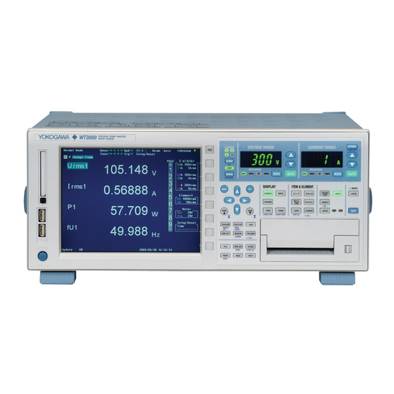
Display Screen Screen Example When Measuring Power (Numeric Display) in Normal Measurement Mode For a description of the screens in other measurement modes and display modes other than power measurement (numeric display), see the respective chapters covering each mode. Measurement mode (see section 3.16) Display of various settings Measurement range (see section 4.3) Display indicating that the... -
Page 27: Chapter 2 Functional Description
Chapter 2 Functional Description System Configuration and Block Diagram System Configuration Load Power Motor supply Current sensor Torque Revolution meter sensor Voltage Current (Input either one) (Input either one) Motor evaluation ELEMENT VOLTAGE ± (Motor version) CURRENT ± Input element Internal memory Store numeric data and waveform display data Recall numeric data and waveform display data... -
Page 28: Block Diagram
2.1 System Configuration and Block Diagram Block Diagram Input element 2 to 4 Input element 1 Voltage input circuit 8.4-inch Element Volt. meas. input circuit 2 to 4 Line RGB output filter (option) Element 1 Freq. meas. input circuit Pulse zero cross trans- detection... -
Page 29: Measurement Modes And Measurement Functions
Functions Measurement Modes The normal measurement mode on the WT3000 allows you to measure voltage, current, power, etc. If the advanced computation (/G6) option is installed, measurements can be performed in a mode specific to each of the functions listed below in addition to the normal measurement mode. -
Page 30: Computation
• Differences in the Harmonic Measurement of Each Measurement Mode In IEC harmonic measurement mode, limitation is placed on a portion of the functions of the WT3000 as compared with the harmonic measurement in normal measurement mode due to the measurement conditions and constraints in the standard. For details, see the table above. - Page 31 Element refers to a set of input terminals that can input a single phase of voltage and current to be measured. The WT3000 can contain up to four elements, which are numbered from 1 to 4. An element number is appended to the measurement function symbol for the measured data that the WT3000 displays, so that the correspondence between the numeric data and the element can be seen.
- Page 32 “Measurement Period” on page 2-7. *1 The WT3000 samples the instantaneous values of the voltage and current signals at a specified sample rate . The sampled data is processed as numeric data or data used to display waveforms on the screen (waveform display data).
- Page 33 Furthermore, the active power and frequency that are measured by the WT3000 and the motor output can be used to compute the motor efficiency and the total efficiency.
- Page 34 2.2 Measurement Modes and Measurement Functions Measurement Period • Measurement Functions of Normal Measurement The measurement period varies depending on the data update rate (see section 2.3) as follows: • When the Data Update Rate Is 50 ms, 100 ms, 5 s, 10 s, or 20 s •...
- Page 35 ΣA or ΣB. For example, there are seven wiring system patterns on a WT3000 that has four input elements installed. • The input element assignment to wiring units ΣA or ΣB is determined from the wiring system pattern.
- Page 36 2.3 Measurement Conditions Measurement Range «For procedures, see section 4.3.» Set the measurement range using an rms level. When directly applying voltage or current signals to the input element, two types of measurement ranges is available, fixed range and auto range. When waveforms are displayed, the vertical display range corresponds to 3 or 6 times the measurement range when the crest factor (see section 4.6) is set to 3 or 6, respectively.
- Page 37 Rms value Input signal waveform The crest factor on the WT3000 is determined by the maximum peak value that can be applied for rated input in terms of a multiplication factor. Peak value that can be input Crest factor (CF) =...
- Page 38 2.3 Measurement Conditions The crest factor can be set to 3 or 6 on the WT3000. The measurable crest factor is as follows: {measurement range × CF setting (3 or 6)} Crest factor (CF) = Measured value (rms value) * However, the peak value of the input signal must be less than or equal to the maximum allowable input.
- Page 39 2.3 Measurement Conditions Averaging «For procedures, see section 4.9.» The averaging function is effective when reading of the numeric display is difficult due to fluctuations. This occurs when the fluctuation of the power supply or the load is large or when the input signal frequency is low.
- Page 40 To capture relatively low frequency signals, select a slow data update rate. The WT3000 automatically selects the computing method from the two averaging computations below according to the data update rate. For details, see appendix 7.
- Page 41 Power Measurement The measured data of voltage, current, power, and so on can be displayed by setting the screen to numeric display. By dividing the screen into top and bottom halves, waveform (section 2.7), trend (section 2.8), bar graph (section 2.8), waveform computation (section 2.9), and FFT (section 2.9) can be displayed simultaneously.
- Page 42 2.4 Power Measurement • Changing the Displayed Items By selecting a displayed item, the numeric data value that is displayed at the position can be changed. Change the measurement function of the third item Change the element of the third item •...
- Page 43 Computation By using the data of measurement functions, the following computations can be performed. In addition, a function is provided in which the equation used to determine the measurement function data can be selected. User-Defined Functions «For procedures, see section 5.4.» Equations can be created (defined) by combining the measurement function symbols and operators.
- Page 44 Because the equations for deriving the power for distorted waveforms are not defined, none of the equations can be said to be more correct than the other. Therefore, the WT3000 provides three equations for determining the apparent power and reactive power.
- Page 45 2.5 Computation • TYPE 3 (The Method Used by Harmonic Measurement Mode on the WT1600 and PZ4000) The reactive power of each phase is calculated directly using equation (2). The three- phase apparent power is calculated using equation (4). This computing equation can be selected on models with the advanced computation (/G6) or harmonic measurement (/G5) option.
- Page 46 2.5 Computation Phase Difference «For procedures, see section 5.10» The display format of the phase difference between the voltage and current of each element can be selected. With the voltage of each element as a reference, one format displays the phase difference using 360° in the clockwise direction, and the other format displays lead up to 180°...
-
Page 47: Integration
Integration The WT3000 can integrate the active power (watt hour), the current (ampere hour), the apparent power (volt-ampere-hour), and the reactive power (var-hour). During integration, the measured and computed values of normal measurements can be displayed in addition to the watt hour, current hour, volt-ampere-hour, var-hour and integration time. - Page 48 2.6 Integration • Normal Integration Mode The integration time is set in relative time. The integration is stopped after the specified time elapses or when the integration value reaches the maximum or minimum integration display value. The integration time and value are held at that point.
- Page 49 2.6 Integration • Real-Time Normal Integration Mode The date and time of start and stop of the integration operation are set. The integration is stopped at the specified time or when the integration value reaches the maximum or minimum integration display value. The integration time and value are held at that point.
-
Page 50: Waveform Display
Waveform Display The WT3000 displays waveforms based on the data sampled within the data update rate. Selecting the Waveform to Be Displayed «For procedures, see section 6.2.» You can select whether to show or hide the voltage and current waveforms of each input element. - Page 51 Waveform sampling data: Data derived by making an A/D conversion of the input signal The A/D conversion rate is approximately 200 kS/s on the WT3000. Therefore, if the data update rate is set to 1 s, the number of waveform sampling data points in a single measurement is approximately 200,000 for an input signal (see the figure below).
- Page 52 • Retrieval of waveform display data The WT3000 retrieves waveform display data to the memory at a sampling rate of approximately 200 kS/s. The frequency that allows displaying of waveforms that are close to the input signal is up to approximately 10 kHz.
- Page 53 2.7 Waveform Display Trigger «For procedures, see section 6.4.» A trigger is a cue used to display the waveform on the screen. The trigger is activated when the specified trigger condition is met. At this point, the waveform is ready to be displayed on the screen.
- Page 54 2.7 Waveform Display Zooming Vertically on the Waveform «For procedures, see section 6.5.» Each displayed waveform can be expanded or reduced vertically by the zoom factor in the range of 0.1 to 100. The waveform is zoomed around the zero input line. When the zoom factor is doubled 300 Vpk 300 Vpk...
- Page 55 2.7 Waveform Display Split Display of the Waveform and Assignment of Waveforms «For procedures, see section 6.6.» The screen can be evenly divided and the waveforms can be assigned to the divided windows. The screen can be divided into up to four windows. This function is useful when there are many waveforms on the screen.
- Page 56 2.7 Waveform Display Displaying Waveform Labels «For procedures, see section 6.8.» Waveform labels can be turn ON or OFF. Upper limit Waveform label Lower limit Time at the right end of the screen Time at the left end of the screen Cursor Measurement «For procedures, see sections 6.9 and 7.8.»...
-
Page 57: Trend, Bar Graph, And Vector Displays
Trend, Bar Graph, and Vector Displays Trends of each measurement function, bar graphs of harmonics of each order, and vectors of the fundamental signal of each element (when using the harmonic measurement option) can be displayed. Trend display The trends of all measurement functions that are measured during normal measurement and harmonic measurement are displayed. - Page 58 2.8 Trend, Bar Graph, and Vector Displays Bar Graph Display of Harmonic Data «See the Expansion Function User’s Manual IM760301-51E .» On models with the advanced computation (/G6) or harmonic measurement (/G5) option, the amplitude of each harmonic can be displayed on the bar graph. The horizontal axis represents harmonic order, and the vertical axis represents the amplitude of each harmonic.
-
Page 59: Waveform Computation And Fft
Waveform Computation and FFT Waveform Computation «See the Expansion Function User’s Manual IM760301-51E .» Various computations can be performed on the waveform data of the input signal on models with the advanced computation (/G6) option. For example, the waveform data of the voltage and current input signals can be multiplied together to display the waveform of instantaneous power. -
Page 60: Voltage Fluctuation And Flicker And Cycle-By-Cycle Measurements
2.10 Voltage Fluctuation and Flicker and Cycle-by- Cycle Measurements Voltage Fluctuation and Flicker Measurement Expansion Function User’s Manual IM760301-51E .» Voltage fluctuation and flicker measurements conforming to IEC61000-3-3 can be performed on models with the voltage fluctuation and flicker measurement (/FL) option. Cycle-by-Cycle Measurement «See the Expansion Function User’s Manual IM760301- 51E .»... -
Page 61: Saving And Loading Data And Other Functions
PC card cannot be recalled. Saving and Loading from the Storage Medium «For procedures, see chapter 12.» The WT3000 comes standard with a PC card drive. A USB port (peripheral devices) is also available as an option. The numeric data, waveform display data, waveform sampling data, screen image data, and setup parameters can be saved to a PC card or USB memory. - Page 62 • Accessing the WT3000 from a PC or Workstation (FTP Server Function) You can access the WT3000 from an FTP client* on the network and retrieve the files on the PC card of the WT3000 or USB storage (optional). The FTP server function can be used when a PC card or USB storage is connected to the WT3000.
- Page 63 Zero-Level Compensation «For procedures, see section 10.1.» Zero-level compensation refers to creating a zero input condition inside the WT3000 and setting the level at that point as the zero level. Zero-level compensation must be performed in order to satisfy the specifications of this instrument (see chapter 12).
- Page 64 NULL values. Selecting the Sampling Frequency «For procedures, see section 10.3.» The WT3000 has three types of sampling frequencies at approximately 200 kHz to prevent the input waveform from being measured as a DC signal due to aliasing (see section 2.7).
-
Page 65: Handling Precautions
OFF the power and unplug the power cord. In addition, turn OFF the power to the circuit under measurement that is connected to the input terminals. If these symptoms occur, contact your nearest YOKOGAWA dealer. • Do Not Damage the Power Cord Nothing should be placed on top of the power cord. -
Page 66: Installing The Instrument
• Install the instrument so that you can immediately remove the power cord if an abnormal or dangerous condition occurs.. CAUTION If you block the inlet or outlet holes on the WT3000, the WT3000 will become hot and may break down. Installation Conditions Install the instrument indoors that meets the following conditions. - Page 67 3.2 Installing the Instrument Storage Location When storing the instrument, avoid the following places: • Where the relative humidity is 80% • Where the level of mechanical vibration is or more. high. • In direct sunlight. • Where corrosive or explosive gas is present. •...
-
Page 68: Connecting The Power Supply
OFF. • To prevent electric shock or fire, always use the power cord supplied by YOKOGAWA. • Make sure to perform protective grounding to prevent the possibility of electric shock. Connect the power cord to a three-prong power outlet with a protective earth terminal. -
Page 69: Turning On/Off The Power Switch
For the initial settings, see appendix 3.13. If the instrument still does not work properly when the power switch is turned ON after checking these items, contact your nearest YOKOGAWA dealer for repairs. Index... - Page 70 ON. If this message appears frequently, the battery must be replaced quickly. The user cannot replace the battery. Contact your nearest YOKOGAWA dealer to have the battery replaced. For information regarding battery life, see section 11.6.
-
Page 71: Wiring Precautions
Wiring Precautions To prevent the possibility of electric shock and damage to the instrument, follow the warnings below. WARNING • Employ protective earth ground before connecting measurement cables. The power cord that comes with the instrument is a three-pin type power cord. Connect the power cord to a properly grounded three-prong outlet. - Page 72 3.5 Wiring Precautions • After connecting the measurement cable, attach the current input protection cover using the screws provided for your safety (screw tightening torque: 0.6 N•m). Make sure that the conductive parts are not exposed from the protection cover. •...
- Page 73 Because current does not flow through the measurement circuit of the WT3000, the measured value may become 0 A, but the input peak over-range indicator at the top section of the screen illuminates in red. If this happens, the measured value is approximately 0 A, but current is actually flowing through the circuit under measurement.
-
Page 74: Assembling The Adapter To Be Connected To The Voltage Input Terminal
Voltage Input Terminal Assembling the 758931 Safety Terminal Adapter When connecting a measurement cable to the voltage input terminal of the WT3000, use the 758931 Safety Terminal Adapter that comes with the package or the 758923 Safety Terminal Adapter that is sold separately. When using the 758931 Safety Terminal Adapter, assemble it according to the following procedure. - Page 75 3.6 Assembling the Adapter to Be Connected to the Voltage Input Terminal Explanation Use the adapters that come with the WT3000 or the adapters and various sensors sold separately for the WT3000 according to the object being wired as follows: •...
-
Page 76: Wiring For Making Accurate Measurements
Wiring for Making Accurate Measurements To make accurate measurements, wire the voltage input terminal and current input terminal by referring to the items below. • Effects of Stray Capacitance When measuring a single-phase device, the effects of stray capacitance on the measurement accuracy can be minimized by connecting the current input terminal of the instrument to the side that is close to the earth potential of the power source (SOURCE). -
Page 77: Guide For Selecting The Method Used To Measure The Power
For example, if you replace the WT2000 (used in a three-phase, three-wire system) Index with the WT3000 and leave the wiring unchanged, the measured power of each element is different between the WT2000 and the WT3000. Refer to this manual and wire the system correctly. 3-13... -
Page 78: Wiring The Circuit Under Measurement For Direct Input
Wiring the Circuit under Measurement for Direct Input The measurement cable is wired directly from the circuit under measurement to the voltage/current input terminal. To prevent the possibility of electric shock and damage to the instrument, follow the precautions given in section 3.5, “Wiring Precautions.” Connecting to the Input Terminal •... - Page 79 3.9 Wiring the Circuit under Measurement for Direct Input The assignment of elements to the input terminals in the figures of the wiring examples below varies depending on the number of installed input elements. For details, see “Number of Installed Input Elements and Wiring Systems” in section 2.3, “Measurement Conditions.”...
- Page 80 3.9 Wiring the Circuit under Measurement for Direct Input Wiring Example of a Three-Phase, Three-Wire System (3P3W) If four input elements are available, two three-phase, three-wire systems can be set up (elements 1 and 2 and elements 3 and 4). ±...
-
Page 81: Wiring The Circuit Under Measurement When Using The Current Sensor
3.10 Wiring the Circuit under Measurement When Using the Current Sensor To prevent the possibility of electric shock and damage to the instrument, follow the precautions given in section 3.5, “Wiring Precautions.” If the maximum current value of the circuit under measurement exceeds the maximum range of the current input terminal as described below, an external sensor can be connected to the current sensor input connector in order to measure the current of the measurement circuit. - Page 82 Area of space created by the connection wires current sensor External sensor cable OUT H (B9284LK, sold separately) WT3000 ± Shielded wire OUT L • For a shunt-type current sensor, connect it to the power earth ground side as shown in the figure below.
- Page 83 3.10 Wiring the Circuit under Measurement When Using the Current Sensor The following wiring examples are for connecting shunt-type current sensors. When connecting a clamp-type current sensor that outputs voltage, substitute the shunt-type current sensor with the clamp-type. In addition, the assignment of elements to the input terminals in the following figure varies depending on the number of installed input elements.
- Page 84 3.10 Wiring the Circuit under Measurement When Using the Current Sensor Wiring Example of a Three-Phase, Three-Wire System (3P3W) Using a Shunt-Type Current Sensor SOURCE LOAD ± OUT H OUT L ± OUT L OUT H Input terminal 1 Input terminal 2 ±...
-
Page 85: Wiring The Circuit Under Measurement When Using The Vt/Ct
3.11 Wiring the Circuit under Measurement When Using the VT/CT Connect a measurement cable from an external voltage transformer (VT) or current transformer (CT) to the voltage or current input terminal of the input element. Wire according to the procedure in this section also when using a clamp-type current sensor that outputs current. - Page 86 3.11 Wiring the Circuit under Measurement When Using the VT/CT Note • After wiring, the wiring system must be selected. See section 4.1, “Selecting the Wiring System.” • The thick lines on the wiring diagrams are the sections where the current flows. Use appropriate wires that are suitable for the current.
- Page 87 3.11 Wiring the Circuit under Measurement When Using the VT/CT Wiring Example of a Three-Phase, Three-Wire System (3P3W) Using VT and CT LOAD SOURCE L CT L CT ± ± ± ± Input terminal 1 Input terminal 2 Wiring Example of a Three-Phase, Three-Wire System (Three-Voltage, Three-Current System) [3P3W (3V3A)] Using VT and CT SOURCE LOAD...
-
Page 88: Setting The Date/Time
3.12 Setting the Date/Time Procedure DISPLAY ITEM & ELEMENT REMOTE RESET UPDATE NUMERIC WAVE U / I / P HOLD LOCAL RATE Cursor keys WP/q/ OTHERS SINGLE TIME PAGE PAGE USER ITEM FORM ELEMENT INTEG SHIFT START STOP LOWER ITEM LOWER FORM USER SET To exit the menu during operation, press ESC located above... - Page 89 3.12 Setting the Date/Time • Setting the Time Using the SNTP Server (Available when the Ethernet interface option is installed) To obtain the time from the SNTP server, you must first connect to the network and then to the SNTP server. For details, see section 5.2, “Setting TCP/IP” and section 5.7, “Setting the Time Difference from GMT (Greenwich Mean Time)/Setting SNTP”...
-
Page 90: Initializing The Settings
3.13 Initializing the Settings Procedure DISPLAY ITEM & ELEMENT REMOTE RESET UPDATE NUMERIC WAVE U / I / P HOLD LOCAL RATE Cursor keys WP/q/ OTHERS SINGLE TIME PAGE PAGE ITEM FORM USER ELEMENT INTEG SHIFT START STOP LOWER ITEM LOWER FORM USER SET To exit the menu during operation, press ESC located above... - Page 91 (option) and Ethernet communication (option). • Initializing at Power Up If the power switch is turned ON while holding down RESET, the WT3000 powers up using initial settings. In this case, “Settings That Cannot Be Initialized” as indicated above excluding the date and time are also initialized. A message indicating that settings have been initialized is shown on the screen.
-
Page 92: Entering Values And Character Strings
3.14 Entering Values and Character Strings Entering Values After selecting the setup parameter with the SET key and soft keys, the value can be changed using the cursor keys. Use the left and right cursor keys to move along the digits and the up and down cursor keys to set the value of that digit. - Page 93 Up to five equations can be stored. After five equations have been stored, a new equation overwrites the oldest equation. • Recalling the Temporarily Stored Equation The procedure varies depending on the WT3000 firmware version as follows: • Version 1.0x on the keyboard and press SET. A window opens and the temporarily Select stored equation is displayed.
- Page 94 3.14 Entering Values and Character Strings Moves the cursor upward. Moves the cursor downward. Switches between upper case and lower case. Deletes the character before the entry position. Switches between insert and overwrite mode. Recalls the temporarily stored string. Enters the string. •...
- Page 95 3.14 Entering Values and Character Strings • Keys Other Than the Character Keys • BS: Deletes the character before the entry position. • INS: Switches between insert and overwrite mode. During insert mode, the INSERT indicator on the keyboard illuminates. When a new character is entered in insert mode, the new character is placed at the entry position and all following characters are moved backward.
-
Page 96: Entering Character Strings On The Usb Keyboard
100 mA cannot be connected simultaneously to the two ports. Connection Procedure Connect the USB keyboard to the WT3000 directly using a USB cable as shown below. You can connect/disconnect a USB cable at any time regardless of the power ON/OFF state of the WT3000 (supports hot-plugging). - Page 97 Executing functions corresponding to the keys on the front panel of the WT3000 The functions corresponding to the front panel keys of the WT3000 are assigned to the keys on the USB keyboard. By pressing the keys on the keyboard, you can operate the WT3000 in a similar fashion.
-
Page 98: Switching The Measurement Mode And Display
3.16 Switching the Measurement Mode and Display Procedure DISPLAY ITEM & ELEMENT REMOTE RESET UPDATE NUMERIC WAVE U / I / P HOLD LOCAL RATE Cursor keys WP/q/ OTHERS SINGLE TIME PAGE PAGE ITEM FORM USER ELEMENT INTEG SHIFT START STOP LOWER ITEM LOWER FORM... - Page 99 3.16 Switching the Measurement Mode and Display Bar graph Waveform computation Trend Split display Split display Vector IEC harmonic Split display Voltage fluctuation Split display and flicker Cycle by cycle Press the Next1/3 Press the Next2/3 soft key. soft key. •...
- Page 100 3.16 Switching the Measurement Mode and Display Measurement Mode Display Normal measurement mode Normal Mode Wide bandwidth harmonic measurement mode Wide-Band Harmonics IEC harmonic measurement mode IEC Harmonics Mode Waveform computation mode Math Mode FFT mode FFT Mode Voltage Fluctuation and Flicker Measurement Mode* Flicker Mode Cycle-by-Cycle Measurement Mode* Cycle by Cycle Mode...
- Page 101 3.16 Switching the Measurement Mode and Display Explanation You can select the display on the WT3000 as indicated below. On models with the advanced computation option, you can select the measurement mode and display in addition to normal measurement mode as shown on the next page.
- Page 102 3.16 Switching the Measurement Mode and Display • Measurement Modes and Display Modes on Models with the Advanced Computation (/G6), Voltage Fluctuation and Flicker Measurement (/FL), or Cycle- by-Cycle Measurement (/CC) Option Measurement Mode Display Mode Voltage Cycle by Fluctuation Cycle Wide Bandwidth IEC Harmonic...
-
Page 103: Displaying The Setup Parameter List
3.17 Displaying the Setup Parameter List Procedure To exit the menu during VOLTAGE RANGE CURRENT RANGE EXT SENSOR operation, press ESC ELEMENT SENSOR RATIO located above the soft keys. ELEMENT In the procedural explanation below, the COMPEN phrase “press the cursor MEASURING MEASURING AUTO... - Page 104 3.17 Displaying the Setup Parameter List • Relation Table of Elements and Measurement Ranges (Page 1) The following figure shows an example when the crest factor is set to 3. • Relation Table of the Rotating Speed of Motor Evaluation Function (Motor Version) and Input Ranges of Torque (Page 2) Displayed only on models with the motor evaluation function (motor version).
-
Page 105: Selecting The Message Language
3.18 Selecting the Message Language Procedure DISPLAY ITEM & ELEMENT REMOTE RESET UPDATE NUMERIC WAVE U / I / P HOLD LOCAL RATE Cursor keys WP/q/ OTHERS SINGLE TIME PAGE PAGE ITEM FORM USER ELEMENT INTEG SHIFT START STOP LOWER ITEM LOWER FORM USER SET To exit the menu during operation, press ESC located above... - Page 106 3.18 Selecting the Message Language Explanation • Selecting the Message Language An error message is displayed when an error occurs. Select the language to use to display these messages and help messages (see section 10.8) from the choices below. The error codes for the error messages are the same for both English and Japanese.
-
Page 107: Setting The Usb Keyboard Language
The character that is entered through each key of the USB keyboard varies depending on the keyboard type. For details, see appendix 9. Note For USB keyboards that have been tested for compatibility, contact your nearest YOKOGAWA dealer. Index 3-43 IM 760301-01E... -
Page 108: Chapter 4 Measurement Conditions
Chapter 4 Measurement Conditions Selecting the Wiring System Procedure To exit the menu during VOLTAGE RANGE CURRENT RANGE EXT SENSOR operation, press ESC ELEMENT SENSOR RATIO located above the soft keys. ELEMENT In the procedural explanation below, the COMPEN MEASURING phrase “press the cursor MEASURING AUTO... - Page 109 4.1 Selecting the Wiring System Explanation • Wiring System Pattern • The five wiring systems below are available. Limitations are placed on the wiring systems that can be selected depending on the number of input elements that are installed in the instrument.
- Page 110 4.1 Selecting the Wiring System • Wiring System Display The wiring system configuration is displayed at the right side of the screen. Because it is displayed behind the menu, press the ESC key to hide the menu (allowing the configuration to be viewed). Below are examples showing the wiring systems on a model with four input elements installed.
-
Page 111: Selecting Independent Setting Of Input Elements
Selecting Independent Setting of Input Elements Procedure To exit the menu during VOLTAGE RANGE CURRENT RANGE EXT SENSOR operation, press ESC ELEMENT SENSOR RATIO located above the soft keys. ELEMENT In the procedural explanation below, the phrase “press the cursor COMPEN MEASURING MEASURING... - Page 112 4.2 Selecting Independent Setting of Input Elements Explanation In the wiring system settings, you can select whether to set the measurement range or synchronization source of input elements in the same wiring unit collectively or independently. • Turning ON/OFF the Independent Setting of Input Elements For example, assume that the wiring system on a model with three input elements is set as follows: Input elements 1 to 3: Three-phase, four-wire system (3P4W).
- Page 113 Setting the Measurement Range for Direct Input Procedure To exit the menu during VOLTAGE RANGE CURRENT RANGE EXT SENSOR operation, press ESC ELEMENT SENSOR RATIO located above the soft keys. ELEMENT In the procedural explanation below, the phrase “press the cursor COMPEN MEASURING MEASURING...
- Page 114 4.3 Setting the Measurement Range for Direct Input Explanation • Display Position of the Target Element and Specified Range When a voltage or current range selection key is pressed, the element is displayed in the voltage or current range indicator (7-segment LED) and at the upper-right corner of the screen.
- Page 115 WT3000 (approximately 200 ks/S). • If the high frequency components of the pulse waveform attenuate due to the bandwidth limiting by the WT3000 measurement circuit and the waveform peak value is less than the peak over-range detection level. •...
- Page 116 4.3 Setting the Measurement Range for Direct Input • Power Range The measurement ranges (power ranges) of active power (P), apparent power (S), and reactive power (Q) are as follows: Wiring System Power Range 1P2W (single-phase, two-wire) voltage range × current range 1P3W (single-phase, three-wire) voltage range ×...
- Page 117 4.3 Setting the Measurement Range for Direct Input The combinations of the actual voltage and current ranges and the power range are listed below according to the table on the previous page (when the voltage or current range of each element is set to the same range). The table shows the active power range (unit: W).
- Page 118 4.3 Setting the Measurement Range for Direct Input • When the crest factor is set to 6 Active Power Range of Each Element Current Voltage Range (V) Range 7.5000 15.0000 30.0000 50.0000 75.000 150.000 300.000 500.000 2.50000m 18.7500 mW 37.5000 mW 75.000 mW 125.000 mW 187.500 mW...
-
Page 119: Setting The Measurement Range When Using The External Current Sensor
Setting the Measurement Range When Using the External Current Sensor Procedure To exit the menu during VOLTAGE RANGE CURRENT RANGE EXT SENSOR operation, press ESC ELEMENT SENSOR RATIO located above the soft keys. ELEMENT In the procedural explanation below, the phrase “press the cursor COMPEN MEASURING... - Page 120 4.4 Setting the Measurement Range When Using the External Current Sensor • Setting the External Current Sensor Transformation Ratio Press SHIFT+EXT SENSOR (SENSOR RATIO) to display the Sensor Ratio menu. Only the installed elements are displayed. • Selecting the Target Element Press one of the soft keys corresponding to the displayed element to select the target element.
- Page 121 4.4 Setting the Measurement Range When Using the External Current Sensor Explanation The output of current sensors that output voltage, such as shunts and clamps, can be input to the current sensor input connector of an element and measured. When using a current sensor that outputs current, set the transformation ratio as a CT ratio (see section 4.5).
-
Page 122: Setting The Scaling Function When Using Vt/Ct
Setting the Scaling Function When Using VT/ Procedure DISPLAY ITEM & ELEMENT REMOTE RESET UPDATE U / I / P NUMERIC WAVE HOLD LOCAL RATE Cursor keys WP/q/ OTHERS SINGLE TIME PAGE PAGE ITEM FORM USER ELEMENT INTEG SHIFT START STOP LOWER ITEM LOWER FORM... - Page 123 4.5 Setting the Scaling Function When Using VT/CT • Setting the CT Ratio Press the Scaling Item soft key to select CT. • Selecting the Target Element Press one of the soft keys corresponding to the displayed element to select the target element.
- Page 124 4.5 Setting the Scaling Function When Using VT/CT Explanation Set the VT ratio when applying the output from the secondary side to the voltage input terminal.. Then, set the voltage range according to the maximum value of the VT output (see section 4.3).
-
Page 125: Selecting The Crest Factor
Selecting the Crest Factor Procedure DISPLAY ITEM & ELEMENT REMOTE RESET UPDATE NUMERIC WAVE U / I / P HOLD LOCAL RATE Cursor keys WP/q/ OTHERS SINGLE TIME PAGE PAGE ITEM FORM USER ELEMENT INTEG SHIFT START STOP LOWER ITEM LOWER FORM USER SET To exit the menu during operation, press ESC located above... -
Page 126: Setting The Measurement Period
Setting the Measurement Period Procedure To exit the menu during VOLTAGE RANGE CURRENT RANGE EXT SENSOR operation, press ESC ELEMENT SENSOR RATIO located above the soft keys. ELEMENT In the procedural explanation below, the COMPEN phrase “press the cursor MEASURING MEASURING AUTO MODE... - Page 127 4.7 Setting the Measurement Period Explanation The measurement period is determined by the data update rate and the synchronization source specified by carrying out the procedure in this section. For details, see appendix 6. During normal measurement, the numeric data is measured/computed from the data sampled within the measurement period.
- Page 128 4.7 Setting the Measurement Period • Measurement Period • When the data update rate is 50 ms, 100 ms, 5 s, 10 s, or 20 s You must set the measurement period. The measurement period is set between the first point where the synchronization source crosses the level zero point (center of the amplitude) on the rising slope (or falling slope) within the data update period and the last point where the synchronization source crosses the level zero point (center of the amplitude) on the rising slope (or falling slope) within the update...
-
Page 129: Selecting The Input Filter
Selecting the Input Filter Procedure DISPLAY ITEM & ELEMENT REMOTE RESET UPDATE NUMERIC WAVE U / I / P HOLD LOCAL RATE Cursor keys WP/q/ OTHERS SINGLE TIME PAGE PAGE ITEM FORM USER ELEMENT INTEG SHIFT START STOP LOWER ITEM LOWER FORM USER SET To exit the menu during operation, press ESC located above... - Page 130 In addition, if the display update interval of the WT3000 is set to 50 ms, 100 ms, 5 s, 10 s, or 20 s, it affects the detection of the measurement period for voltage, current, and power measurements (see appendix 6 and 7).
-
Page 131: Selecting The Averaging Function
Selecting the Averaging Function Procedure DISPLAY ITEM & ELEMENT REMOTE RESET UPDATE NUMERIC WAVE U / I / P HOLD LOCAL RATE Cursor keys WP/q/ OTHERS SINGLE TIME PAGE PAGE ITEM FORM USER ELEMENT INTEG SHIFT START STOP LOWER ITEM LOWER FORM USER SET To exit the menu during operation, press ESC located above... - Page 132 4.9 Selecting the Averaging Function Explanation For functional details, see section 2.3. The averaging function is effective when reading of the numeric display is difficult due to fluctuations. This occurs when the fluctuation of the power supply or the load is large or when the input signal frequency is low.
- Page 133 4.9 Selecting the Averaging Function • Setting the Attenuation Constant • Harmonic Measurement in Normal Measurement Mode If averaging is turned ON and the averaging type is Exp (exponential averaging), exponential averaging is performed using the selected attenuation constant (2, 4, 8, 16, 32, or 64).
-
Page 134: Selecting The Data Update Rate
4.10 Selecting the Data Update Rate Procedure To exit the menu during VOLTAGE RANGE CURRENT RANGE EXT SENSOR operation, press ESC ELEMENT SENSOR RATIO located above the soft keys. ELEMENT In the procedural explanation below, the COMPEN MEASURING phrase “press the cursor MEASURING AUTO MODE... - Page 135 The measured value may not be stable if an AC signal of a frequency lower than the lower limit of measurement frequency (see section 12.4) is measured. • The WT3000 automatically switches the method of computing the measured values according to the data update rate. For details, see appendix 7. •...
-
Page 136: Hold And Single Measurement
4.11 Hold and Single Measurement Procedure To exit the menu during VOLTAGE RANGE CURRENT RANGE EXT SENSOR operation, press ESC ELEMENT SENSOR RATIO located above the soft keys. ELEMENT In the procedural explanation below, the phrase “press the cursor COMPEN MEASURING MEASURING keys”... -
Page 137: Chapter 5 Power Measurement
Chapter 5 Power Measurement Displaying Numeric Data and Changing the Displayed Items Procedure To exit the menu during VOLTAGE RANGE CURRENT RANGE EXT SENSOR operation, press ESC ELEMENT SENSOR RATIO located above the soft keys. ELEMENT In the procedural explanation below, the COMPEN phrase “press the cursor MEASURING... - Page 138 5.1 Displaying Numeric Data and Changing the Displayed Items The following procedures are given as typical examples in which the display mode is set to Numeric (numeric data on the entire screen). • Selecting the Number of Displayed Items Press FORM to display the Numeric Form menu. Press any of the soft keys from 4 Items, 8 Items, 16 Items, All Items, Single List*, and Dual List* to select the number of displayed items.
- Page 139 5.1 Displaying Numeric Data and Changing the Displayed Items • Changing Using the Function Select Keys The display of measurement functions of U, I, P, S, Q, λ, φ, WP, q, TIME, FU, FI, and η and the element/wiring unit can be changed using function select keys. •...
- Page 140 5.1 Displaying Numeric Data and Changing the Displayed Items • Selecting from the Menu Press ITEM to display the Numeric menu. • Selecting the Item to Be Changed Press the Item No. soft key. Press the cursor keys to select the item to be changed. The item to be changed is highlighted.
- Page 141 5.1 Displaying Numeric Data and Changing the Displayed Items • Resetting the Order of the Displayed Items Press ITEM to display the Numeric menu. Press the Reset Items Exec soft key. An Alert dialog box appears. Press the cursor keys to select OK or Cancel. Select OK and press SET to reset the order of the displayed items on all pages.
- Page 142 5.1 Displaying Numeric Data and Changing the Displayed Items Measurement Functions of Normal Measurement • Symbol and Meaning of the Displayed Measurement Functions U (voltage Urms, Umn, Udc, Urmn), I (current Irms, Imn, Idc, Irmn) P (active power), S (apparent power) Q (reactive power), λ...
- Page 143 5.1 Displaying Numeric Data and Changing the Displayed Items • Selecting the Number of Displayed Items Select the number of numeric data items that are displayed simultaneously from the choices below. • 4 Items • When the display mode is Numeric, Numeric + Wave, Numeric + Bar , and Numeric + Trend, four numeric data values are displayed in one column.
- Page 144 5.1 Displaying Numeric Data and Changing the Displayed Items • Changing the Measurement Function • The types of measurement functions that can be selected are the items that are indicated in “Types of Measurement Functions during Normal Measurement” of section 2.2, “User-Defined Function” and Corrected Power of section 2.5, “Measurement Functions of Integration,”...
-
Page 145: Selecting The Voltage/Current Mode (Rms, Mean, Dc, Or Rmean)
Selecting the Voltage/Current Mode (RMS, MEAN, DC, or RMEAN) Procedure To exit the menu during VOLTAGE RANGE CURRENT RANGE EXT SENSOR operation, press ESC ELEMENT SENSOR RATIO located above the soft keys. ELEMENT In the procedural explanation below, the phrase “press the cursor COMPEN MEASURING MEASURING... -
Page 146: Selecting The Frequency Measurement Source
Selecting the Frequency Measurement Source Procedure To exit the menu during VOLTAGE RANGE CURRENT RANGE EXT SENSOR operation, press ESC ELEMENT SENSOR RATIO located above the soft keys. ELEMENT In the procedural explanation below, the COMPEN phrase “press the cursor MEASURING MEASURING AUTO... - Page 147 5.3 Selecting the Frequency Measurement Source Explanation • You can select two of the input signals of the installed elements to measure the frequency. However, there is no need to specify the frequency measurement signals on the models with the frequency measurement add-on option, because frequencies of all elements can be measured.
-
Page 148: Setting The User-Defined Function
Setting the User-Defined Function Procedure DISPLAY ITEM & ELEMENT REMOTE RESET UPDATE NUMERIC WAVE U / I / P HOLD LOCAL RATE Cursor keys WP/q/ OTHERS SINGLE TIME PAGE PAGE ITEM FORM USER ELEMENT INTEG SHIFT START STOP LOWER ITEM LOWER FORM USER SET To exit the menu during operation, press ESC located above... - Page 149 5.4 Setting the User-Defined Function • Setting the Unit Press the cursor keys to select Unit. Press SET. A keyboard appears. Use the keyboard to set the unit. For keyboard operations, see section 3.14, “Entering Values and Strings.” • Setting the Equation Press the cursor keys to select Expression.
- Page 150 5.4 Setting the User-Defined Function • Equation Types The combination of the measurement function and element number (Urms1, for example) can be used as an operand to create up to 20 equations (F1 to F20). There can be up to 16 operands in one equation. Some operands cannot be computed in measurement modes other than normal measurement mode.
- Page 151 5.4 Setting the User-Defined Function • Setting the Operand Parameters There are two types of operands with parameters. • Setting Operands with Two Parameters Set a symbol representing the element in the left parameter and the order in the right parameter.For example, set the parameters as in (E1,OR2). •...
- Page 152 5.4 Setting the User-Defined Function The user-defined functions allow you to determine physical values other than those of the measurement functions by combining operands. The measurement functions that can be assigned to the efficiency equation (section 5.7) are fixed to power and motor output.
-
Page 153: Setting Max Hold
Setting MAX hold Procedure DISPLAY ITEM & ELEMENT REMOTE RESET UPDATE NUMERIC WAVE U / I / P HOLD LOCAL RATE Cursor keys WP/q/ OTHERS SINGLE TIME PAGE PAGE ITEM FORM USER ELEMENT INTEG SHIFT START STOP LOWER ITEM LOWER FORM USER SET To exit the menu during operation, press ESC located above SCALING... - Page 154 5.5 Setting MAX hold Explanation Maximum Hold This function enables the maximum value of the numeric data to be held. • The item to be held at the maximum value is set using the user-defined function. The operators for the measurement functions are shown below in the form measurement function: MAX value (equation for defining the MAX hold).
-
Page 155: Measuring The Average Active Power
Measuring the Average Active Power Explanation The average active power is specified using the user-defined function as follows: Integrated power Average active power = Elapsed time of integration For example, to determine the average active power of element 1, the equation of the user-defined function is set as follows: WH(E1)/(TI(E1)/3600) The unit of TI ( ) is seconds (S). -
Page 156: Setting The Equation For Efficiency
Setting the Equation for Efficiency Procedure To exit the menu during VOLTAGE RANGE CURRENT RANGE EXT SENSOR operation, press ESC ELEMENT SENSOR RATIO located above the soft keys. ELEMENT In the procedural explanation below, the COMPEN phrase “press the cursor MEASURING MEASURING AUTO... - Page 157 5.7 Setting the Equation for Efficiency Explanation An efficiency equation can be created by combining the measurement function symbols. Using the numeric values of the measurement functions, the energy conversion efficiency of the device can be determined. • Setting the Equation Four efficiency equations (h1 to h4) can be defined by assigning the power of an element, the power of a S function, or the motor output as an operand.
-
Page 158: Setting The Wiring, Efficiency, And Two-Wattmeter Method Compensations
Setting the Wiring, Efficiency, and Two- Wattmeter Method Compensations Procedure To exit the menu during VOLTAGE RANGE CURRENT RANGE EXT SENSOR operation, press ESC ELEMENT SENSOR RATIO located above the soft keys. ELEMENT In the procedural explanation below, the phrase “press the cursor COMPEN MEASURING MEASURING... - Page 159 5.8 Setting the Wiring, Efficiency, and Two-Wattmeter Method Compensations • Turning ON/OFF the Efficiency Compensation Press the cursor keys to select Efficiency Compensation. Press SET to select ON or OFF. • Turning ON/OFF the Compensation for Two-Wattmeter Method This appears only when the wiring system is set to 3P3W (3V3A) on models with the delta computation option.
- Page 160 5.8 Setting the Wiring, Efficiency, and Two-Wattmeter Method Compensations • Efficiency Compensation The power measurement on the secondary side of a power transformer such as an inverter includes loss caused by the measurement instrument. This loss appears as error in the efficiency computation. This function compensates for this loss. For details, see appendix 8.
-
Page 161: Setting The Equations For Apparent Power, Reactive Power, And Corrected Power
Setting the Equations for Apparent Power, Reactive Power, and Corrected Power Procedure DISPLAY ITEM & ELEMENT REMOTE RESET UPDATE U / I / P NUMERIC WAVE HOLD LOCAL RATE Cursor keys WP/q/ OTHERS SINGLE TIME PAGE PAGE ITEM FORM USER ELEMENT INTEG SHIFT... - Page 162 5.9 Setting the Equations for Apparent Power, Reactive Power, and Corrected Power • Setting the Equation for Corrected Power Press the Pc Formula soft key to display the Pc Formula dialog box. • Selecting the Applicable Standard Press the cursor keys to select the standard for Pc Formula. Press SET to select either IEC76-1(1976), IEEE C57.12.90-1993 or IEC76- 1(1993).
- Page 163 5.9 Setting the Equations for Apparent Power, Reactive Power, and Corrected Power Explanation • Selecting the Equations for Apparent Power and Reactive Power The equations for apparent power and reactive power can be selected from three types. For details, see section 2.5. •...
-
Page 164: Selecting The Display Format Of The Phase Difference
5.10 Selecting the Display Format of the Phase Difference Procedure DISPLAY ITEM & ELEMENT REMOTE RESET UPDATE NUMERIC WAVE U / I / P HOLD LOCAL RATE Cursor keys WP/q/ OTHERS SINGLE TIME PAGE PAGE ITEM FORM USER INTEG ELEMENT SHIFT START STOP... - Page 165 5.10 Selecting the Display Format of the Phase Difference Explanation The phase difference f between the voltage and current indicates the position of the current phase with respect to the voltage of each element. You can select the display mode from below. •...
-
Page 166: Integration
The WT3000 keys are used to Section 5.12 operation operation start/stop the integration. Normal integration mode A WT3000 key is used to start the Stopped by Section 5.13 integration. When a specified operation a timer timer value elapses, the integration is stopped. - Page 167 • Error: The WT3000 stores and holds the integration result even when a power failure occurs while integration is in progress. When the power recovers, the integration result calculated up to the point when the power failure occurred is displayed with the integration operation stopped.
- Page 168 5.11 Integration • Holding, Starting, and Stopping the Integration When the display is held, the display of the integration result and communication output are held. The integration operation continues regardless of whether the hold function is ON or OFF. The relationship between the hold function and the start and stop operations is as follows: •...
- Page 169 5.11 Integration • Display Resolution The maximum display resolution of the integration value is 999999. When the integrated value reaches 1000000 counts, the decimal point shifts automatically. For example, if 0.001 mWh is added to 999.999 mWh, the display shows 1.00000 Wh. •...
- Page 170 5.11 Integration • Limitation on Modifying the Settings during Integration When the integration is in progress, settings of some functions cannot be changed as shown below. Integration Operation Condition Integration Reset Integrating Integration Suspended (START indicator) (STOP indicator) Function Wiring system Measurement range Scaling Filter...
-
Page 171: Setting The Manual Integration
5.12 Setting the Manual Integration Procedure To exit the menu during VOLTAGE RANGE CURRENT RANGE EXT SENSOR operation, press ESC ELEMENT SENSOR RATIO located above the soft keys. ELEMENT In the procedural explanation below, the phrase “press the cursor COMPEN MEASURING MEASURING keys”... - Page 172 • Holding the Integration Press HOLD. The HOLD key illuminates, and the numeric data display is held. Integration continues inside the WT3000. • Releasing the Hold Operation Press HOLD while the values are held. The HOLD key turns OFF, and the numeric data display is updated.
- Page 173 5.12 Setting the Manual Integration Explanation For functional details, see section 2.6. To perform integration, the integration mode and integration time must be set before starting the operation. • Selecting the Integration Mode and Setting the Integration Timer If the integration mode is set to normal integration and the integration timer is set to 00000:00:00, the integration is performed in manual integration mode.
-
Page 174: Setting The Normal Integration And Repetitive Integration
5.13 Setting the Normal Integration and Repetitive Integration Procedure To exit the menu during VOLTAGE RANGE CURRENT RANGE EXT SENSOR operation, press ESC ELEMENT SENSOR RATIO located above the soft keys. ELEMENT In the procedural explanation below, the phrase “press the cursor COMPEN MEASURING MEASURING... - Page 175 5.13 Setting the Normal Integration and Repetitive Integration • Setting the Integration Timer Press the Timer Setting soft key to display the Timer Setting dialog box. Press the cursor keys to select the hour, minute, or second box. Press SET to display the entry box. Press the cursor keys to set the hour, minute, or second that you selected in step 6.
- Page 176 5.13 Setting the Normal Integration and Repetitive Integration Explanation For functional details, see section 2.6. To perform integration, the integration mode and integration time must be set before starting the operation. • Selecting the Normal Integration Mode or Repetitive Integration Mode In this mode, the integration time is set in relative time and the integration is performed over the specified time.
-
Page 177: Setting The Real-Time Integration And Real-Time Repetitive Integration
5.14 Setting the Real-Time Integration and Real- Time Repetitive Integration Procedure To exit the menu during VOLTAGE RANGE CURRENT RANGE EXT SENSOR operation, press ESC ELEMENT SENSOR RATIO located above the soft keys. ELEMENT In the procedural explanation below, the phrase “press the cursor COMPEN MEASURING... - Page 178 5.14 Setting the Real-Time Integration and Real-Time Repetitive Integration • Setting the Integration Timer Press the Timer Setting soft key to display the Timer Setting dialog box. Press the cursor keys to select the hour, minute, or second box. Press SET to display the entry box. Press the cursor keys to set the hour, minute, or second that you selected in step 6.
- Page 179 5.14 Setting the Real-Time Integration and Real-Time Repetitive Integration • Integrating in Real-time Normal Integration Mode or Real-time Repetitive Integration Mode • Starting the Integration Press INTEG to display the Integ menu. Press the START soft key. The START indicator to the right of the INTEG key illuminates and the instrument enters the ready condition.
- Page 180 5.14 Setting the Real-Time Integration and Real-Time Repetitive Integration Explanation For functional details, see section 2.6. To perform integration, the integration mode and integration time must be set before starting the operation. • Selecting the Real-time Normal Integration Mode or Real-time Repetitive Integration Mode In this mode, integration is performed between the times specified by integration start and stop.
-
Page 181: Turning On/Off The Integration Auto Calibration
5.15 Turning ON/OFF the Integration Auto Calibration Procedure To exit the menu during VOLTAGE RANGE CURRENT RANGE EXT SENSOR operation, press ESC ELEMENT SENSOR RATIO located above the soft keys. ELEMENT In the procedural explanation below, the phrase “press the cursor COMPEN MEASURING MEASURING... -
Page 182: Chapter 6 Waveform Display
Chapter 6 Waveform Display Waveform Display Procedure To exit the menu during VOLTAGE RANGE CURRENT RANGE EXT SENSOR operation, press ESC ELEMENT SENSOR RATIO located above the soft keys. ELEMENT In the procedural explanation below, the phrase “press the cursor COMPEN MEASURING MEASURING... - Page 183 6.1 Waveform Display Explanation For functional details, see section 2.7. A display example is shown below. For the procedure to change the displayed items and contents of waveforms, see sections 6.2 to 6.8. Distinction of voltage or current, the element, and the upper limit of the displayed waveform Trigger level Ground level...
-
Page 184: Selecting The Waveform To Be Displayed
Selecting the Waveform to Be Displayed Procedure To exit the menu during VOLTAGE RANGE CURRENT RANGE EXT SENSOR operation, press ESC ELEMENT SENSOR RATIO located above the soft keys. ELEMENT In the procedural explanation below, the phrase “press the cursor COMPEN MEASURING MEASURING... - Page 185 6.2 Selecting the Waveform to Be Displayed • Turning ON/OFF the Display the Input Signal Waveforms Collectively • Displaying the Waveforms Collectively Press the cursor keys to select All ON. Press SET. All the buttons to the left of the input signal are highlighted, and all the waveforms are displayed.
-
Page 186: Setting The Time Axis
Setting the Time Axis Procedure To exit the menu during VOLTAGE RANGE CURRENT RANGE EXT SENSOR operation, press ESC ELEMENT SENSOR RATIO located above the soft keys. ELEMENT In the procedural explanation below, the phrase “press the cursor COMPEN MEASURING MEASURING keys”... - Page 187 6.3 Setting the Time Axis Explanation For functional details, see section 2.7. Set the time axis in terms of Time/div (time per grid). The time axis can be set in 1, 2, or 5 steps in the range up to the point in which the time corresponding to one screen is equal to the data update interval.
-
Page 188: Setting The Trigger
Setting the Trigger Procedure To exit the menu during VOLTAGE RANGE CURRENT RANGE EXT SENSOR operation, press ESC ELEMENT SENSOR RATIO located above the soft keys. ELEMENT In the procedural explanation below, the phrase “press the cursor COMPEN MEASURING MEASURING keys”... - Page 189 6.4 Setting the Trigger • Selecting the Trigger Mode Press the Mode soft key to select Auto or Normal. • Selecting the Trigger Source Press the Source soft key. A trigger source selection box appears. Press the cursor keys to select any of the elements/wiring units starting with Press SET to confirm the new trigger source.
- Page 190 6.4 Setting the Trigger Explanation For functional details, see section 2.7. A trigger is a cue used to display the waveform on the screen. The trigger is activated when the specified trigger condition is met. At this point, the waveform is ready to be displayed on the screen.
- Page 191 6.4 Setting the Trigger • Input Circuit for the External Trigger Signal and Time Chart +5 V EXT CLK 100 Ω External trigger signal Minimum pulse width External trigger (when set to Trigger delay time Internal trigger • Selecting the Trigger Slope The up and down movement of a signal level is called a slope.
- Page 192 6.4 Setting the Trigger Note • To prevent erroneous operation caused by noise, the trigger function uses approximately 2% hysteresis if the crest factor is set to 3. For example, if the trigger slope is set to , a trigger occurs if the input signal passes through the trigger level on the rising edge after the input signal level falls approximately 2% below the trigger level.
- Page 193 Zooming Vertically and Moving the Vertical Position Procedure To exit the menu during VOLTAGE RANGE CURRENT RANGE EXT SENSOR operation, press ESC ELEMENT SENSOR RATIO located above the soft keys. ELEMENT In the procedural explanation below, the phrase “press the cursor COMPEN MEASURING MEASURING...
- Page 194 6.5 Zooming Vertically and Moving the Vertical Position • Zooming in on the Voltage Waveform Press the (U) V Zoom soft key. Press the cursor keys to set the zoom rate. • Moving the Voltage Waveform Position Press the (U) Position soft key. If the crest factor is set to 3 or 6, press the cursor keys to set the position in terms of a percentage with the value equal to measurement range ×...
-
Page 195: Zooming Vertically And Moving The Vertical Position
6.5 Zooming Vertically and Moving the Vertical Position Explanation • Selecting the Target Element to Be Specified Only the installed elements are displayed. The Element menu is displayed according to the element configuration of the product. • Zoom (Vertical Direction Only) You can expand or reduce each displayed waveform (voltage/current). -
Page 196: Waveform Display On Divided Windows
Waveform Display on Divided Windows Procedure To exit the menu during VOLTAGE RANGE CURRENT RANGE EXT SENSOR operation, press ESC ELEMENT SENSOR RATIO located above the soft keys. ELEMENT In the procedural explanation below, the phrase “press the cursor COMPEN MEASURING MEASURING keys”... - Page 197 6.6 Waveform Display on Divided Windows • Selecting the Waveform Mapping Press the Wave Mapping soft key to display the Wave Mapping dialog box. Press SET to set the mode to Auto, Fixed, or User. If you selected User, proceed to step 6. Press the cursor keys to select the input signal you wish to set.
- Page 198 6.6 Waveform Display on Divided Windows Explanation The screen can be evenly divided and the waveforms can be assigned to the divided windows. • Selecting the Number of Divisions Select the number of divisions of the screen from the choices below. •...
- Page 199 Selecting the Display Interpolation and Graticule Procedure To exit the menu during VOLTAGE RANGE CURRENT RANGE EXT SENSOR operation, press ESC ELEMENT SENSOR RATIO located above the soft keys. ELEMENT In the procedural explanation below, the phrase “press the cursor COMPEN MEASURING MEASURING...
- Page 200 6.7 Selecting the Display Interpolation and Graticule • Changing the Graticule Press the Graticule soft key to select , or Explanation For functional details, see section 2.7. • Selecting Whether to Interpolate the Display When there are less than 500 points of sampled data on the time axis, the area between the display points (rasters) is no longer continuous.
-
Page 201: Selecting The Display Interpolation And Graticule
6.7 Selecting the Display Interpolation and Graticule • Changing the Graticule Select the grid or cross scale to display on the screen from the choices below. • : Grid display • : No grid or cross scale display • : Cross scale display 6-20 IM 760301-01E... -
Page 202: Turning On/Off The Scale Value And Waveform Label
Turning ON/OFF the Scale Value and Waveform Label Procedure To exit the menu during VOLTAGE RANGE CURRENT RANGE EXT SENSOR operation, press ESC ELEMENT SENSOR RATIO located above the soft keys. ELEMENT In the procedural explanation below, the phrase “press the cursor COMPEN MEASURING MEASURING... - Page 203 6.8 Turning ON/OFF the Scale Value and Waveform Label Explanation • Turning ON/OFF the Scale Value Display You can select whether or not to display (ON/OFF) the upper and lower limits of the vertical axis and the values at the left and right ends of the horizontal axis (time axis, see section 6.3) of each channel.
-
Page 204: Cursor Measurement
Cursor Measurement Procedure DISPLAY ITEM & ELEMENT REMOTE RESET UPDATE NUMERIC WAVE U / I / P HOLD LOCAL RATE Cursor keys WP/q/ OTHERS SINGLE TIME PAGE PAGE ITEM FORM USER ELEMENT INTEG SHIFT START STOP LOWER ITEM LOWER FORM USER SET To exit the menu during operation, press ESC located above SCALING... - Page 205 6.9 Cursor Measurement • Selecting the Target Waveform for Cursor Measurement • Selecting the Target Waveform for Cursor + Press the Wave C1 Trace soft key. A box used to select the target waveform appears. Press the cursor keys to select any of the elements/wiring units starting with Press SET to confirm the new target waveform.
- Page 206 • 1/∆X: Reciprocal of the difference between the X-axis values of cursor + and cursor x • Movement Path of the Cursor Since the WT3000 P-P compresses the sampled data (see section 2.7), two data points, maximum and minimum values, are displayed at the same time axis position.
-
Page 207: Chapter 7 Trend Display
Chapter 7 Trend Display Trend Display Procedure To exit the menu during VOLTAGE RANGE CURRENT RANGE EXT SENSOR operation, press ESC ELEMENT SENSOR RATIO located above the soft keys. ELEMENT In the procedural explanation below, the phrase “press the cursor COMPEN MEASURING MEASURING... - Page 208 7.1 Trend Display Explanation A display example is shown below. The horizontal axis is expressed in terms of time as shown below. The trend value in the hold condition (see section 4.11) is the same as the numeric data when HOLD is pressed. When hold is released, the trend that was held is displayed.
-
Page 209: Selecting The Trend Data To Be Displayed
Selecting the Trend Data to Be Displayed Procedure To exit the menu during VOLTAGE RANGE CURRENT RANGE EXT SENSOR operation, press ESC ELEMENT SENSOR RATIO located above the soft keys. ELEMENT In the procedural explanation below, the phrase “press the cursor COMPEN MEASURING MEASURING... - Page 210 7.2 Selecting the Trend Data to Be Displayed • Turning ON/OFF the Trend Display Collectively • Displaying the Trends Collectively Press the cursor keys to select All ON. Press SET. All the buttons to the left of the trend symbols are highlighted, and all the trend are displayed.
-
Page 211: Selecting The Trend Display Target
Selecting the Trend Display Target Procedure To exit the menu during VOLTAGE RANGE CURRENT RANGE EXT SENSOR operation, press ESC ELEMENT SENSOR RATIO located above the soft keys. ELEMENT In the procedural explanation below, the phrase “press the cursor COMPEN MEASURING MEASURING keys”... - Page 212 7.3 Selecting the Trend Display Target • Selecting the Item to Be Set Press the Trend Object soft key. Press the cursor keys to select a value between T1 and T16. • Selecting the Measurement Function Press the Function soft key. The measurement function selection box appears. Press the cursor keys to select any of the measurement functions starting with Press SET to confirm.
- Page 213 7.3 Selecting the Trend Display Target Explanation Set the item to be shown on the trend display. You can set 16 lines of trends, trend 1 (T1) through trend 16 (T16). • Selecting the Measurement Function • The measurement functions that can be selected are the items that are indicated in “Types of Measurement Functions during Normal Measurement”...
-
Page 214: Setting The Time Axis
Setting the Time Axis Procedure To exit the menu during VOLTAGE RANGE CURRENT RANGE EXT SENSOR operation, press ESC ELEMENT SENSOR RATIO located above the soft keys. ELEMENT In the procedural explanation below, the COMPEN phrase “press the cursor MEASURING MEASURING AUTO keys”... - Page 215 7.4 Setting the Time Axis Explanation Set the time axis in terms of T/div (time per grid). Set the time per division in the range of 3 s to 1 day. The data update interval of the trend is determined by the data update rate and the time axis (T/div).
-
Page 216: Setting The Scale
Setting the Scale Procedure To exit the menu during VOLTAGE RANGE CURRENT RANGE EXT SENSOR operation, press ESC ELEMENT SENSOR RATIO located above the soft keys. ELEMENT In the procedural explanation below, the COMPEN phrase “press the cursor MEASURING MEASURING AUTO keys”... - Page 217 7.5 Setting the Scale • Selecting the Target Trend to Be Scaled Press the Trend Object soft key. Press the cursor keys to select a value between T1 and T16. • Selecting Auto Scaling or Manual Scaling Press the Scaling soft key to select Auto or Manual. •...
-
Page 218: Displaying Trends On Divided Windows
Displaying Trends on Divided Windows Procedure To exit the menu during VOLTAGE RANGE CURRENT RANGE EXT SENSOR operation, press ESC ELEMENT SENSOR RATIO located above the soft keys. ELEMENT In the procedural explanation below, the COMPEN phrase “press the cursor MEASURING MEASURING AUTO... - Page 219 7.6 Displaying Trends on Divided Windows Explanation The trends can be assigned to the divided windows. • Selecting the Number of Screen Divisions Select the number of divisions of the screen from the choices below. This is the same as with the waveform display (section 6.6). •...
-
Page 220: Value And Waveform Label
Selecting the Display Interpolation and Graticule and Turning ON/OFF the Scale Value and Waveform Label Procedure To exit the menu during VOLTAGE RANGE CURRENT RANGE EXT SENSOR operation, press ESC ELEMENT SENSOR RATIO located above the soft keys. ELEMENT In the procedural explanation below, the phrase “press the cursor COMPEN... - Page 221 7.7 Selecting the Display Interpolation and Graticule and Turning ON/OFF the Scale Value and Waveform Label Explanation • Selecting Whether to Interpolate the Display Same as the explanation given in “Selecting Whether to Interpolate the Display” in section 6.7. • Changing the Graticule Same as the explanation given in “Changing the Graticule”...
-
Page 222: Restarting The Trend
Restarting the Trend Procedure To exit the menu during VOLTAGE RANGE CURRENT RANGE EXT SENSOR operation, press ESC ELEMENT SENSOR RATIO located above the soft keys. ELEMENT In the procedural explanation below, the COMPEN phrase “press the cursor MEASURING MEASURING AUTO keys”... -
Page 223: Cursor Measurement
Cursor Measurement Procedure DISPLAY ITEM & ELEMENT REMOTE RESET UPDATE NUMERIC WAVE U / I / P HOLD LOCAL RATE Cursor keys WP/q/ OTHERS SINGLE TIME PAGE PAGE ITEM FORM USER ELEMENT INTEG SHIFT START STOP LOWER ITEM LOWER FORM USER SET To exit the menu during operation, press ESC located above SCALING... - Page 224 7.9 Cursor Measurement • Turning ON/OFF Cursor Measurement Press the Trend Cursor soft key to select ON or OFF. If ON is selected, the result of the cursor measurement is displayed. • Selecting the Target Trend for Cursor Measurement • Selecting the Target Trend for Cursor + Press the TrendC1 Trace soft key.
- Page 225 7.9 Cursor Measurement Explanation • ON/OFF A cursor can be placed on the displayed trend to measure and display the value at any point. It can be used to measure the data on the vertical axis (Y-axis) and horizontal axis (X-axis) of various sections of the trend. •...
-
Page 226: Chapter 8 Storing And Recalling Data And Saving The Stored Data
Chapter 8 Storing and Recalling Data and Saving the Stored Data Setting the Store Mode Procedure DISPLAY ITEM & ELEMENT REMOTE RESET UPDATE NUMERIC WAVE U / I / P HOLD LOCAL RATE Cursor keys WP/q/ OTHERS SINGLE TIME PAGE PAGE ITEM FORM... - Page 227 8.1 Setting the Store Mode Explanation To store data, parameters such as the store mode, the store count, the store interval, and the store reservation time must be specified before executing the operation. This section explains the store mode. For the procedure on how to set the store count, the store interval, and the store reservation time, see section 8.2;...
-
Page 228: Setting The Numeric Data And Waveform Display Data To Be Stored
Setting the Numeric Data and Waveform Display Data to Be Stored Procedure DISPLAY ITEM & ELEMENT REMOTE RESET UPDATE U / I / P NUMERIC WAVE HOLD LOCAL RATE Cursor keys WP/q/ OTHERS SINGLE TIME PAGE PAGE ITEM FORM USER ELEMENT INTEG SHIFT... - Page 229 8.2 Setting the Numeric Data and Waveform Display Data to Be Stored • Selecting the Numeric Data to Be Stored (This operation is valid if the stored item was set to Numeric or Numeric+Wave in step 5.) Press the List Item soft key to display the List Item dialog box. •...
- Page 230 8.2 Setting the Numeric Data and Waveform Display Data to Be Stored • Selecting the Waveform Display Data to Be Stored (This operation is valid if the stored item was set to Wave or Numeric+Wave in step 5.) Press the Wave Trace soft key to display the Wave Trace dialog box. •...
- Page 231 8.2 Setting the Numeric Data and Waveform Display Data to Be Stored Explanation • Selecting the Items to Be Stored Select the item to be stored from the following: • Numeric Numerical data are stored. • Wave Waveform display data are stored. •...
-
Page 232: Setting The Store Count, Store Interval, Store Reservation Time, And Alert Indication Of Internal Memory Initialization
Setting the Store Count, Store Interval, Store Reservation Time, and Alert Indication of Internal Memory Initialization Procedure DISPLAY ITEM & ELEMENT REMOTE RESET UPDATE NUMERIC WAVE U / I / P HOLD LOCAL RATE Cursor keys WP/q/ OTHERS SINGLE TIME PAGE PAGE ITEM... - Page 233 8.3 Setting the Store Count, Store Interval, Store Reservation Time, and Alert Indication of Internal Memory Initialization • Checking the Maximum Store Count and Optimizing the Store Count Press the Optimize Store Count soft key. The Optimize Store Count dialog box appears, and the maximum store count is displayed.
- Page 234 8.3 Setting the Store Count, Store Interval, Store Reservation Time, and Alert Indication of Internal Memory Initialization • Setting the Store Reservation Time (This operation is possible when the store mode is set to Real Time in section 8.1) Press the Mode soft key to display the Mode menu. Press the Real Time soft key to select the real-time mode.
- Page 235 8.3 Setting the Store Count, Store Interval, Store Reservation Time, and Alert Indication of Internal Memory Initialization Explanation To store data, parameters such as the store mode, the store count, the store interval, and the store reservation time must be specified before executing the operation. This section explains the store count, the store interval, and the store reservation time.
-
Page 236: Storing Data
• During real-time mode The WT3000 enters store ready state. The STORE key blinks, and “Store:Ready” is displayed in the upper left corner of the screen. When the reservation time for starting the storage operation is reached, the first storage operation starts. - Page 237 8.4 Storing Data • Stopping the Storage Operation If the storage operation is in progress, pressing STORE again stops the operation. The STORE key turns OFF. • Automatically Stopping the Storage Operation The storage operation stops automatically according to the following conditions depending on the store mode.
- Page 238 The data stored to the internal memory cannot be retained by the internal lithium battery. The data in the internal memory is lost when the power to the WT3000 is turned OFF. To retain the data, save the data to the storage medium before turning off the power.
-
Page 239: Saving The Stored Data
Saving the Stored Data CAUTION Do not remove the PC card or USB memory or turn OFF the power when the access indicator or icon of the PC card or USB memory is blinking. This can damage the PC card or USB memory or destroy the data on it. Procedure DISPLAY ITEM &... - Page 240 8.5 Saving the Stored Data When Saving Data That Has Already Been Stored Press the Memory to File soft key to display the Memory to File dialog box. • Selecting the Data Type for Saving the Data Press the Data Type soft key to select ASCII or Float. •...
- Page 241 8.5 Saving the Stored Data • Executing the Save Operation Press the Memory to File Exec soft key. The stored data is saved to the directory indicated by Path=..At the same time, the Memory to File Exec soft key changes to an Abort soft key. •...
- Page 242 8.5 Saving the Stored Data When Saving Data through a Store-and-Save Operation Sequence Press the File setting soft key to display the File setting menu. • Selecting the Data Type for Saving the Data The procedure is the same as step 5 under “Selecting the Data Type for Saving the Data”...
- Page 243 • Numerical data or waveform display data is saved in ASCII format. • The file can be used on your PC for analysis. • The file cannot be loaded into the WT3000. • Float • Numeric data or waveform display data is saved in 32-bit floating format.
- Page 244 8.5 Saving the Stored Data • File Name and Comment • A file name must be assigned. Comments are optional. • You cannot save data to a file name that already exists in the same directory (overwriting not allowed). Number and Types of Characters That Can Be Used Item Number of Characters Characters That Can Be Used...
- Page 245 • Files that do not have an archive attribute are not displayed in the File List window. Do not remove the archive attribute of the files saved by the WT3000 using your PC. • Up to 41 characters can be displayed in the path. If the path exceeds 41 characters, “...” is displayed at the end of the character string.
-
Page 246: Recalling The Stored Data
Recalling the Stored Data Procedure DISPLAY ITEM & ELEMENT REMOTE RESET UPDATE NUMERIC WAVE U / I / P HOLD LOCAL RATE Cursor keys WP/q/ OTHERS SINGLE TIME PAGE PAGE ITEM FORM USER ELEMENT INTEG SHIFT START STOP LOWER ITEM LOWER FORM USER SET To exit the menu during operation, press ESC located above... - Page 247 8.6 Recalling the Stored Data Explanation • Recalling the Data You can recall and display the stored numeric data or waveform display data. There is a one-to-one relationship between the store count number (see section 8.2) and the Recall No. If you wish to recall the first stored data, for example, set Recall No.
-
Page 248: Chapter 9 Saving And Loading Data
Insert the PC card into the PC card drive with the front side of the card facing right. Note Be sure to insert the PC card all the way in. If it isn’t, the WT3000 may not detect it correctly. Ejecting the PC Card Check that the PC card is not being accessed and press the eject button below the PC card slot. - Page 249 USB memories (USB Mass Storage Class) can be used on the WT3000. Connecting the USB Memory Connect the USB memory directly to the WT3000 without going through a USB hub. You can connect the USB memory regardless of whether the power switch on the WT3000 is ON or OFF (supports hot-plugging).
-
Page 250: Formatting The Storage Media
Such acts can damage the storage medium or destroy the data on it. • If the WT3000 fails to detect a formatted storage medium, reformat the storage medium on the WT3000. Note that all the data on the storage medium are cleared when the storage medium is formatted. - Page 251 9.2 Formatting the Storage Media • Selecting the Storage Medium to Be Formatted Press the Format soft key. A storage media list is displayed in the File List dialog box. Press the cursor keys to select the storage medium to be formatted. Net Work (drive) cannot be formatted.
- Page 252 9.2 Formatting the Storage Media Explanation • Storage Medium Information Lists the information about the selected storage medium. • Media Name: Storage medium name. • Media Size: Total size. • Used Space: Size of the used area. • Vacant Space: Size of the free area.
-
Page 253: Saving Setup Parameters, Waveform Display Data, Numeric Data, Waveform Sampling Data
Saving Setup Parameters, Waveform Display Data, Numeric Data, Waveform Sampling Data DISPLAY ITEM & ELEMENT REMOTE RESET UPDATE NUMERIC WAVE U / I / P HOLD LOCAL RATE Cursor keys WP/q/ OTHERS SINGLE TIME PAGE PAGE ITEM FORM USER ELEMENT INTEG SHIFT START... - Page 254 9.3 Saving Setup Parameters, Waveform Display Data, Numeric Data, Waveform Sampling Data Selecting the Waveform Display Data • Selecting the Type of Waveform Display Data to Be Saved Press the Data Type soft key to display the Data Type menu. Press any of the soft keys from Binary to Float soft key to select the data type.
- Page 255 9.3 Saving Setup Parameters, Waveform Display Data, Numeric Data, Waveform Sampling Data Selecting the Numeric Data • Selecting the Type of Numeric Data to Be Saved (for Measurement Modes Other Than Cycle-by-Cycle) Press the Data Type soft key to select ASCII or Float. Note The data type is fixed to ASCII for the cycle-by-cycle measurement.
- Page 256 9.3 Saving Setup Parameters, Waveform Display Data, Numeric Data, Waveform Sampling Data • Setting the Items One at a Time Press the cursor keys to select the element or measurement function that you wish to specify. Press SET. When the button to the left of the selected element or measurement function is highlighted, the numeric data of the measurement function of the element will be saved.
- Page 257 9.3 Saving Setup Parameters, Waveform Display Data, Numeric Data, Waveform Sampling Data Executing/Aborting the Save Operation Press ESC to close the List Item dialog box. Press the Save soft key to display the Save Menu. Press the File List soft key to display the File List dialog box. •...
- Page 258 9.3 Saving Setup Parameters, Waveform Display Data, Numeric Data, Waveform Sampling Data • Executing the Save Operation Press the Save Exec soft key. The data is saved to the directory indicated by Path=..At the same time, the Save Exec soft key changes to the Abort soft key.
- Page 259 9.3 Saving Setup Parameters, Waveform Display Data, Numeric Data, Waveform Sampling Data Explanation CAUTION Do not remove the storage medium (disk) or turn OFF the power when the access indicator or is blinking. Doing so can damage the storage medium or destroy the data on the medium.
- Page 260 • The file cannot be loaded into the WT3000. Note The waveform display data that is saved on the WT3000 is not the sampled data acquired at the sample rate (approximately 200 kS/s) of the WT3000. The waveform display data is waveform sampling data that has been P-P compressed (see the note in section 2.7) to a set...
- Page 261 • ASCII • Saved in ASCII format. • The file can be used on your PC for analysis. • The file cannot be loaded into the WT3000. • Float • Saved in 32-bit floating format. • The file cannot be loaded into the WT3000.
- Page 262 4 to 7 is recorded for the data of all cycles of that input signal. • Saving the Waveform Sampling Data Select Acquisition from the File Item menu to save waveform sampling data.* * Data acquired at the WT3000’s sample rate (200 kS/s). Index 9-15...
- Page 263 • ASCII header file (.hdr) • Waveform display data is saved in binary format. • For details on the ASCII header file, see appendix 3. • Neither file can be loaded into the WT3000. • ASCII • Saved in ASCII format.
- Page 264 9.3 Saving Setup Parameters, Waveform Display Data, Numeric Data, Waveform Sampling Data • Extension and Data Size Data Type Extension Data Size (Bytes) Binary .wvf Approx. (8K + 4 × the number of waveform sampling data points × Tw) where Tw is the number of displayed waveforms .hdr Approx.
- Page 265 9.3 Saving Setup Parameters, Waveform Display Data, Numeric Data, Waveform Sampling Data • Executing the Save Operation • The save operation may take several seconds to several hours depending on the number of waveforms to be saved, the data type, the number of waveform sampling data points determined by the data update rate, and the data transfer rate to the save destination medium.
- Page 266 2500 files, change the directory or move the existing files to another directory. • The header section of the saved file is in a common format used by YOKOGAWA’s measuring instruments. Therefore, data that is not used by the SL1400 is also included.
-
Page 267: Saving The Screen Image Data
Saving the Screen Image Data CAUTION Do not remove the PC card or USB memory or turn OFF the power when the access indicator or icon of the PC card or USB memory is blinking. This can damage the PC card or USB memory or destroy the data on the it. - Page 268 9.4 Saving the Screen Image Data • Setting Comments Press the Comment soft key. A keyboard appears. Use the keyboard to enter the comment. For keyboard operations, see section 3.14, “Entering Values and Strings.” • Selecting the Storage Medium and Directory Press the File List soft key to display the File List dialog box.
- Page 269 9.4 Saving the Screen Image Data • Setting the file name Press the File Name soft key to display the File Name dialog box. Press the cursor keys to select Auto Naming. Press SET to select ON or OFF. Press the cursor keys to select File Name. Press SET.
- Page 270 • Files that do not have an archive attribute are not displayed in the File List window. Do not remove the archive attribute of the files saved by the WT3000 using your PC. • Up to 41 characters can be displayed in the path. If the path exceeds 41 characters, “...” is displayed at the end of the character string.
-
Page 271: Loading Setup Parameters
Loading Setup Parameters CAUTION Do not remove the PC card or USB memory or turn OFF the power when the access indicator or icon of the PC card or USB memory is blinking. This can damage the PC card or USB memory or destroy the data on the it.n it. Procedure DISPLAY ITEM &... - Page 272 9.5 Loading Setup Parameters Press the Load soft key. The Load Menu and the File List dialog box appears • Selecting the Load Source Storage Medium Press the cursor keys to select the load source storage medium (indicated by [ ]). Press SET to confirm the storage medium.
- Page 273 • Files that do not have an archive attribute are not displayed in the File List window. Do not remove the archive attribute of the files saved by the WT3000 using your PC. • Up to 41 characters can be displayed in the path. If the path exceeds 41 characters, “...” is displayed at the end of the character string.
-
Page 274: Specifying The File To Be Displayed, Displaying File Properties, And Selecting File Attributes
Specifying the File to Be Displayed, Displaying File Properties, and Selecting File Attributes CAUTION Do not remove the PC card or USB memory or turn OFF the power when the access indicator or icon of the PC card or USB memory is blinking. This can damage the PC card or USB memory or destroy the data on the it. - Page 275 9.6 Specifying the File to Be Displayed, Displaying File Properties, and Selecting File Attributes • Specifying the File to Be Displayed in the File List Dialog Box Press the Filter soft key to select Item or All. • If you select Item, the list of files corresponding to the file type (Setup, Wave, or Numeric) that is specified for File Item in the File menu, in the directory selected in step 5, is displayed.
- Page 276 • Files that do not have an archive attribute are not displayed in the File List window. Do not remove the archive attribute of the files saved by the WT3000 using your PC. • Up to 41 characters can be displayed in the path. If the path exceeds 41 characters, “...” is displayed at the end of the character string.
-
Page 277: Deleting Files
Deleting Files CAUTION Do not remove the PC card or USB memory or turn OFF the power when the access indicator or icon of the PC card or USB memory is blinking. This can damage the PC card or USB memory or destroy the data on the it. Procedure DISPLAY ITEM &... - Page 278 9.7 Deleting Files • Specifying the File to Be Displayed in the File List Dialog Box The procedure is the same as that given inin “Specifying the File to Be Displayed in the File List Dialog Box” in section 9.6. •...
- Page 279 • Files that do not have an archive attribute are not displayed in the File List window. Do not remove the archive attribute of the files saved by the WT3000 using your PC. • Up to 41 characters can be displayed in the path. If the path exceeds 41 characters, “...” is displayed at the end of the character string.
-
Page 280: Copying Files
Copying Files CAUTION Do not remove the PC card or USB memory or turn OFF the power when the access indicator or icon of the PC card or USB memory is blinking. This can damage the PC card or USB memory or destroy the data on the it. Procedure DISPLAY ITEM &... - Page 281 9.8 Copying Files • Specifying the File to Be Displayed in the File List Dialog Box The procedure is the same as that given inin “Specifying the File to Be Displayed in the File List Dialog Box” in section 9.6. •...
- Page 282 9.8 Copying Files • Selecting the Copy Destination Press the Dest Dir soft key. The copy execution menu and the copy destination File List dialog box appear. • Selecting the Copy Destination Storage Medium or Directory The procedure is the same as that given inin “Selecting the Storage Medium” and “Selecting the Save Destination Directory”...
- Page 283 • Files that do not have an archive attribute are not displayed in the File List window. Do not remove the archive attribute of the files saved by the WT3000 using your PC. • Up to 41 characters can be displayed in the path. If the path exceeds 41 characters, “...” is displayed at the end of the character string.
-
Page 284: Renaming Files Or Directories And Creating Directories
Renaming Files or Directories and Creating Directories CAUTION Do not remove the PC card or USB memory or turn OFF the power when the access indicator or icon of the PC card or USB memory is blinking. This can damage the PC card or USB memory or destroy the data on the it. Procedure DISPLAY ITEM &... - Page 285 9.9 Renaming Files or Directories and Creating Directories Renaming a Directory or File Press the Rename soft key to display the Rename menu. • Selecting the Storage Medium and Directory The procedure is the same as that given inin “Selecting the Storage Medium” and “Selecting the Save Destination Directory”...
- Page 286 9.9 Renaming Files or Directories and Creating Directories Creating a Directory Press the MakeDir soft key to display the MakeDir menu. • Selecting the Storage Medium and Directory The procedure is the same as that given inin “Selecting the Storage Medium” and “Selecting the Save Destination Directory”...
- Page 287 • Files that do not have an archive attribute are not displayed in the File List window. Do not remove the archive attribute of the files saved by the WT3000 using your PC. • Up to 41 characters can be displayed in the path. If the path exceeds 41 characters, “...” is displayed at the end of the character string.
-
Page 288: Chapter 10 Other Functions
Chapter 10 Other Functions 10.1 Zero-Level Compensation Procedure To exit the menu during VOLTAGE RANGE CURRENT RANGE EXT SENSOR operation, press ESC ELEMENT SENSOR RATIO located above the soft keys. ELEMENT In the procedural explanation below, the phrase “press the cursor COMPEN MEASURING MEASURING... -
Page 289: Null Function
10.2 NULL Function Procedure DISPLAY ITEM & ELEMENT REMOTE RESET UPDATE NUMERIC WAVE U / I / P HOLD LOCAL RATE Cursor keys WP/q/ OTHERS SINGLE TIME PAGE PAGE ITEM FORM USER ELEMENT INTEG SHIFT START STOP LOWER ITEM LOWER FORM USER SET To exit the menu during operation, press ESC located above SCALING... - Page 290 10.2 NULL Function • Measurement Functions Affected by the NULL Function The NULL value is subtracted from the sampled data. Hence, all measurement functions are affected by the NULL values. • Limitations on the NULL Function by Measurement Modes The NULL function cannot be used in the following measurement modes. •...
-
Page 291: Selecting The Sampling Frequency
10.3 Selecting the Sampling Frequency Procedure DISPLAY ITEM & ELEMENT REMOTE RESET UPDATE NUMERIC WAVE U / I / P HOLD LOCAL RATE Cursor keys WP/q/ OTHERS SINGLE TIME PAGE PAGE ITEM FORM USER ELEMENT INTEG SHIFT START STOP LOWER ITEM LOWER FORM USER SET To exit the menu during operation, press ESC located above... -
Page 292: Selecting The Display Font
10.4 Selecting the Display Font Procedure DISPLAY ITEM & ELEMENT REMOTE RESET UPDATE NUMERIC WAVE U / I / P HOLD LOCAL RATE Cursor keys WP/q/ OTHERS SINGLE TIME PAGE PAGE FORM USER ITEM ELEMENT INTEG SHIFT START STOP LOWER ITEM LOWER FORM USER SET To exit the menu during operation, press ESC located above... - Page 293 Note Both the Gothic and Roman fonts used on the WT3000 are original fonts designed by YOKOGAWA. Therefore, the details of each font may differ from that of other devices. 10-6...
-
Page 294: Selecting The Screen Brightness
10.5 Selecting the Screen Brightness Procedure DISPLAY ITEM & ELEMENT REMOTE RESET UPDATE NUMERIC WAVE U / I / P HOLD LOCAL RATE Cursor keys WP/q/ OTHERS SINGLE TIME PAGE PAGE ITEM FORM USER ELEMENT INTEG SHIFT START STOP LOWER ITEM LOWER FORM USER SET To exit the menu during operation, press ESC located above... -
Page 295: Setting The Display Color
10.6 Setting the Display Color Procedure DISPLAY ITEM & ELEMENT REMOTE RESET UPDATE NUMERIC WAVE U / I / P HOLD LOCAL RATE Cursor keys WP/q/ OTHERS SINGLE TIME PAGE PAGE ITEM FORM USER ELEMENT INTEG SHIFT START STOP LOWER ITEM LOWER FORM USER SET To exit the menu during operation, press ESC located above... - Page 296 10.6 Setting the Display Color • Setting User Colors Press the User Color soft key to display the Graph Color dialog box. Press the cursor keys to select the item you wish to set. Press SET. A box used to set the color level appears. Press the cursor keys to set the color level.
- Page 297 10.6 Setting the Display Color Explanation The display color for each item can be specified. Set the color using a ratio (0-7) of red (R), green (G), and blue (B). • Setting the Graphic Color Select default color or a user color. For user color, the display color can be specified for each item.
-
Page 298: Setting The Key Lock And Shift Lock Function
10.7 Setting the Key Lock and Shift Lock Function Procedure DISPLAY ITEM & ELEMENT REMOTE RESET UPDATE NUMERIC WAVE U / I / P HOLD LOCAL RATE Cursor keys WP/q/ OTHERS SINGLE TIME PAGE PAGE ITEM FORM USER ELEMENT INTEG SHIFT START STOP... - Page 299 10.7 Setting the Key Lock and Shift Lock Function Explanation • Key Lock If key lock is turned ON, all keys except the power switch, MISC key, ESC key, and the 5th soft key from the top are disabled. When key lock is ON, the word “Lock” is displayed at the upper right corner of the screen.
-
Page 300: Help Function
10.8 Help Function Procedure DISPLAY ITEM & ELEMENT REMOTE RESET UPDATE NUMERIC WAVE U / I / P HOLD LOCAL RATE Cursor keys WP/q/ OTHERS SINGLE TIME PAGE PAGE ITEM FORM USER ELEMENT INTEG SHIFT START STOP LOWER ITEM LOWER FORM USER SET To exit the menu during operation, press ESC located above SCALING... -
Page 301: Master/Slave Synchronization Measurement
10.9 Master/Slave Synchronization Measurement Procedure DISPLAY ITEM & ELEMENT REMOTE RESET UPDATE NUMERIC WAVE U / I / P HOLD LOCAL RATE Cursor keys WP/q/ OTHERS SINGLE TIME PAGE PAGE ITEM FORM USER ELEMENT INTEG SHIFT START STOP LOWER ITEM LOWER FORM USER SET To exit the menu during operation, press ESC located above... - Page 302 Carry out the hold operation according to the procedure below during synchronized measurement. • Hold ON: Turn the hold function ON from the WT3000 set to master. • Hold OFF: Turn the hold function OFF from the WT3000 set to slave.
- Page 303 10.9 Master/Slave Synchronization Measurement • Input Circuit for the External Start Signal and Time Chart +5 V 100 Ω Start input signal Minimum pulse width Start input signal Input delay time Measurement start Trigger occurrence CAUTION • When the instrument is set to master, do not apply external voltage to the external start signal input/output connector (START).
-
Page 304: Chapter 11 Troubleshooting, Maintenance, And Inspection
• If a message is displayed on the screen, read the following pages. • If servicing is necessary, or if the instrument is not operating correctly after performing the corrective actions, contact your nearest YOKOGAWA dealer. Problem and Corrective Action Reference Section Nothing shows up on the display when the power switch is turned ON. -
Page 305: Error Messages And Corrective Actions
This section describes the meanings of the messages and their corrective actions. The messages can be displayed either in English or Japanese (see section 3.18). If the corrective action requires servicing, contact your nearest YOKOGAWA dealer for repairs. In addition to the error messages listed below, there are communication error messages. - Page 306 11.2 Error Messages and Corrective Actions Code Message Corrective Action Reference Section 682, Printer over heat. Power off immediately. – No built-in printer on this model. Check the specifications to see whether or not Page ii the optional printer is provided. Printer time out.
- Page 307 Cannot be set or executed in the Flicker – –* measurement mode. Attempt made to start flicker measurement Wait for the initialization to finish and the WT3000 –* while flicker initialization is not finished. to become ready. Then, start the measurement. Attempt made to start flicker measurement Reset the flicker measurement, wait for the –*...
- Page 308 11.2 Error Messages and Corrective Actions Code Message Corrective Action Reference Section Attempted made to start integration in real – 5.12 time counting integration mode when the end time had already passed. Attempted made to start storing in real – time counting storing mode when the end time had already passed.
- Page 309 Maintenance service is required. – The USB device’s power consumption – 12.9 exceeded the capacity of the USB hub. Note If the system is not operating correctly or if servicing is necessary, try initializing the WT3000. The WT3000 may recover. 11-6 IM 760301-01E...
-
Page 310: Self-Test
11.3 Self-Test Procedure DISPLAY ITEM & ELEMENT REMOTE RESET UPDATE NUMERIC WAVE U / I / P HOLD LOCAL RATE Cursor keys WP/q/ OTHERS SINGLE TIME PAGE PAGE ITEM FORM USER ELEMENT INTEG SHIFT START STOP LOWER ITEM LOWER FORM USER SET To exit the menu during operation, press ESC located above SCALING... - Page 311 • If the indicator turns ON/OFF when the cursor is pressed, the keys are operating correctly. • To exit from the key test, press ESC twice. • If the display is not correct, contact your nearest YOKOGAWA dealer. 11-8 IM 760301-01E...
-
Page 312: Checking The System Condition
11.4 Checking the System Condition Procedure DISPLAY ITEM & ELEMENT REMOTE RESET UPDATE NUMERIC WAVE U / I / P HOLD LOCAL RATE Cursor keys WP/q/ OTHERS SINGLE TIME PAGE PAGE ITEM FORM USER ELEMENT INTEG SHIFT START STOP LOWER ITEM LOWER FORM USER SET To exit the menu during operation, press ESC located above... -
Page 313: Replacing The Power Fuse
11.5 Replacing the Power Fuse WARNING • To prevent the possibility of fire, only use a fuse with the specified rating (voltage, current, and type). • Be sure to turn OFF the instrument and unplug the power cord before replacing the fuse. -
Page 314: Recommended Replacement Parts
(items which wear out). The replacement period for expendable items varies depending on the conditions of use. Refer to the table below as a general guideline. Contact your nearest YOKOGAWA dealer to have parts replaced. Parts Name Recommended Replacement Period Built-in printer Under normal usage, 200 rolls of printer paper (part No. -
Page 315: Chapter 12 Specifications
Chapter 12 Specifications 12.1 Input Section Item Specifications Input terminal type Voltage Plug-in terminal (safety terminal) Current • Direct input: Large binding post • Current sensor input: Isolated BNC connector Input format Voltage Floating input, resistive voltage divider Current Floating input, shunt input Measurement range Voltage (rated value) -
Page 316: Display
12.1 Input Section/12.2 Display Item Specifications Continuous maximum Voltage input terminals: 1000Vrms common mode voltage Current input terminals*: 1000 Vrms (maximum allowable voltage that can be measured) (50/60 Hz) 600 Vrms (rating voltage of EN61010-2-030) External current sensor input connector: 600 Vrms Influence from common When 1000 Vrms is applied with the voltage input terminals shorted and current input terminals open. -
Page 317: Measurement Functions (Measurement Items) Related To Normal Measurement
12.3 Measurement Functions (Measurement Items) Related to Normal Measurement Measurement Functions Determined for Each Input Element For details on the determination and equations of measurement functions, see appendix 1. Item Symbol and Meaning Voltage (V) Urms: true rms value, Umn: rectified mean value calibrated to the rms value, Udc: simple average, Urmn: rectified mean value Current (A) Irms: true rms value, Imn: rectified mean value calibrated to the rms value, Idc: simple average,... - Page 318 12.3 Measurement Functions (Measurement Items) Related to Normal Measurement Measurement Functions (Σ Functions) Determined for Each Wiring Unit (ΣA and ΣB) For details on the determination and equations of Σ functions, see appendix 1. Item Symbol and Meaning Voltage (V) UrmsΣ: true rms value, UmnΣ: rectified mean value calibrated to the rms value, UdcΣ: simple average, UrmnΣ: rectified mean value Current (A)
-
Page 319: Accuracy
µA I is the current reading (A). The influence from self-generated heat continues until the Index temperature of the shunt resistor inside the WT3000 lowers even if the current input changes to a small value. • When the data update interval is 50 ms, add 0.1% of reading to all accuracy figures. - Page 320 12.4 Accuracy Item Specifications • All accuracy figures for 0.1 to 10 Hz are reference values. • The voltage accuracy figures for 30 kHz to 100 kHz when the voltage exceeds 750 V are reference values. • The voltage accuracy figures for 100 kHz to 1 MHz when the voltage (V) exceeds 2.2 × 10 (kHz) are reference values.
- Page 321 % of reading + 3 × I µ A I is the current reading (A). The influence from self-generated heat continues until the temperature of the shunt resistor inside the WT3000 lowers even if the current input changes to a small value. •...
- Page 322 12.4 Accuracy Item Specifications Effective input range • 0 to ±130% of the power range (see section 5.2) for DC measurement. • ±130% of the power range for current measurement when the voltage and current are in the range of 1 to 130% of the measurement range. However, if the data update interval is 50 ms, 100 ms, 5 s, 10 s, or 20 s, the signal level of the synchronization source must satisfy the input signal level of frequency measurement (see section 12.5).
-
Page 323: Functions
12.5 Functions Measurement Function and Measurement Conditions Item Specifications Measurement method Digital multiplier method Crest factor Select 3 or 6 (when rated value of the measurement range is input) 300 for the minimum effective input. Measurement period Period used to determine and compute the measurement function. •... - Page 324 12.5 Functions Item Specifications Measurement mode Select from the following measurement modes. • Normal measurement mode • Wide bandwidth harmonic measurement mode* • IEC harmonic measurement mode* • Waveform computation mode* • FFT mode* • Voltage fluctuation and flicker measurement mode* •...
- Page 325 12.5 Functions Item Specifications Accuracy ±(Power accuracy (or current accuracy) + timer accuracy) Timer accuracy ±0.02% of reading Computation Item Specifications User-defined function Computes numeric data of equations (up to 20 equations) that are created by combining the measurement function symbols and operators. Average active power setting Set with the user-defined function.
- Page 326 12.5 Functions Item Specifications Display interpolation of the Select dot or linear display. waveform Graticule Select the grid and cross scale display. Auxiliary display ON/OFF Turn ON/OFF the upper and lower limits (scale value) and the waveform label. Cursor measurement Measure the value at the point where the cursor is placed on the waveform.
-
Page 327: Input/Output Of The Master/Slave Synchronization Signal
12.6 Input/Output of the Master/Slave Synchronization Signal Item Specifications Connector type BNC connector: Common to the master and slave I/O level TTL: Common to the master and slave Output logic Negative logic, falling edge: Applicable to the master Measurement start delay Within (1 µ... -
Page 328: Storage
5 V, 500 mA (per port) Number of ports *1 For details on the compatible USB devices, contact your nearest YOKOGAWA dealer. *2 Devices whose maximum current consumption exceeds 100 mA cannot be connected simultaneously to the two ports. 12-14... -
Page 329: Gp-Ib Interface
12.10 GP-IB Interface Item Specifications Devices That Can Be Used NATIONAL INSTRUMENTS • AT-GPIB • PCI-GPIB and PCI-GPIB+ • PCMCIA-GPIB and PCMCIA-GPIB+ Driver: NI-488.2M Ver. 1.60 or later Electrical and mechanical Conforms to IEEE St’d 488-1978 (JIS C 1901-1992). specifications Functional specifications SH1, AH1, T6, L4, SR1, RL1, PP0, DC1, DT1, and C0 Protocol... -
Page 330: General Specifications
12.12 General Specifications Item Specifications Warm-up time Approx. 30 minutes Operating conditions Temperature: 5 to 40° C Humidity : 20 to 80% RH when not using the printer, 35 to 80% RH when using the printer. (No condensation) Operating altitude 2000 m or less Installation location Indoors... - Page 331 Same as the cable condition for emission above. *1 Applies to products with CE marks. For all other products, contact your nearest YOKOGAWA dealer. *2 The Overvoltage Category is a value used to define the transient overvoltage condition and includes the impulse withstand voltage regulation.
-
Page 332: External Dimensions
12.13 External Dimensions Unit: mm Rear View Dimensions with the JIS rack mount kit Rack mount attachment plane 28.9 Dimensions with the EIA rack mount kit 481.1 + 0.4 Rack mount attachment plane 28.9 Unless otherwise specified, tolerance is ±3% (however, tolerance is ±0.3 mm when below 10 mm). 12-18 IM 760301-01E... -
Page 333: Appendix
Appendix Appendix 1 Symbols and Determination of Measurement Functions Measurement Functions during Normal Measurement (Table 1/3) Measurement Functions during Method of Determination, Equation Normal Measurement For details on the symbols in the equation, see the Note on page App-3. Urms Urms Urmn True rms value... - Page 334 Appendix 1 Symbols and Determination of Measurement Functions (Table 2/3) Measurement Functions Method of Determination, Equation during Normal For details on the symbols in the equation, see the Note on page App-3. Measurement Integration time Time from integration start to integration stop. [h:m:s] u(n) i(n)
- Page 335 (/G6) or the harmonic measurement (/G5) option. • S, Q, λ, and φ on the WT3000 are derived through the computation of the measured values of voltage, current, and active power (except Q is calculated directly from the sampled data when TYPE3 is selected ).
- Page 336 Appendix 2 List of Initial Settings and Display Order of Numeric Data Initial Settings (Factory Default, Example for a Model with Four Input Elements Installed) The default settings vary depending on the number of installed input elements and the presence/absence of options. Item Setting RANGE...
- Page 337 Appendix 2 List of Initial Settings and Display Order of Numeric Data Item Setting S,Q Formula Type1 Pc Formula IEC76-1 (1976) P1 and P2 of IEC76-1 (1993) P1 = 0.5000, P2 = 0.5000 Sampling Frequency Auto Phase 180 Lead/Lag Sync Measure Master SYNC SOURCE Element Object...
- Page 338 Appendix 2 List of Initial Settings and Display Order of Numeric Data Item Setting FORM (for Bar, displayed on models with the advanced computation (/G6) or harmonic measurement (/G5) option) Format Single Start Order End Order ITEM (for Trend) Trend Display T1 to T8 Trend Items Trend Object...
- Page 339 Appendix 2 List of Initial Settings and Display Order of Numeric Data Item Setting FORM (for FFT, displayed on models with the advanced computation (/G6) option) Format Single FFT Points Trigger Common to FORM (for Wave) Display Setting Interpolate Common to FORM (for Wave) Graticule Common to FORM (for Wave) Scale Value...
- Page 340 Appendix 2 List of Initial Settings and Display Order of Numeric Data Setting CURSOR (for Wave) Wave Cursor Wave C1 Trace Wave C2 Trace Cursor Path Wave C1 + 10.0 ms Wave C2 × 40.0 ms CURSOR (for Bar, displayed on models with the advanced computation (/G6) or harmonic measurement (/G5) option) Bar Cursor Bar C1 +...
-
Page 341: Appendix 2 List Of Initial Settings And Display Order Of Numeric Data
Appendix 2 List of Initial Settings and Display Order of Numeric Data Item Setting MOTOR SET (displayed on models with the motor evaluation function on the motor version) Scaling (Speed) 1.0000 Scaling (Torque) 1.0000 Scaling (Pm) 1.0000 Unit (Speed) Unit (Torque) Unit (Pm) Analog Auto Range (Speed) - Page 342 Appendix 2 List of Initial Settings and Display Order of Numeric Data Settings That Are Not Initialized through Initialization (MISC-Initialize Settings) Item Setting MISC Remote Control Device GP-IB GP-IB Address RS232 (displayed on models with the RS232 communication option) Baud Rate 19200 Format 8-No-1...
- Page 343 Appendix 2 List of Initial Settings and Display Order of Numeric Data Example of the Display Order of Numeric Data (Example for a Model with Four Input Elements Installed) • When the order of the numeric data is reset, the measurement function data are displayed in the order given in the next table.
- Page 344 Appendix 2 List of Initial Settings and Display Order of Numeric Data ALL Item Display Display Page U+pk Time η1 U(k) U(k) Uthd φU1-U2 U-pk η2 I(k) I(k) Ithd φU1-U3 I+pk η3 P(k) P(k) Pthd φU1-I1 I-pk η4 S(k) Q(k) Uthf φU1-I2 ∆F1...
- Page 345 • Waveform display data file (.wvf) • ASCII header file (.hdr) The ASCII header files explained here cannot be viewed on the WT3000. Use the data in such cases as when analyzing the waveforms on your PC. //YOKOGAWA ASCII FILE FORMAT...
- Page 346 0.0000000E+00 HUnit Date 2001/08/30 2001/08/30 Time 07:03:03 07:03:03 $PrivateInfo ModelVersion 1.01 (Note) The header file is a common file used by YOKOGAWA’s measuring instruments. Therefore, data that is not required by the WT3000 (0s) is also included. App-14 IM 760301-01E...
- Page 347 Trace: Format in which each block contains a waveform *3 Start position of the binary waveform display data Offset from the beginning of the file. Always 8192 on the WT3000 *4 Maximum number of blocks in the group Maximum number of blocks when the number of blocks varies for each waveform. Always 1 on the WT3000.
-
Page 348: Appendix 4 Power Basics (Power, Harmonics, And Rlc Of Ac Circuits)
Appendix 4 Power Basics (Power, Harmonics, and RLC of AC Circuits) This chapter describes the basics of power, harmonic, and RLC of AC circuits. Power Electrical energy is converted into other types of energy for use such as in the form of heat for electrical heaters and furnaces, turning force for motors, and light for fluorescent lamps or mercury lamps. - Page 349 Appendix 4 Power Basics (Power, Harmonics, and RLC of AC Circuits) In the case of the mean value, simply taking the average over 1 period of the sine wave results in zero. Therefore, the average is taken over 1 period of absolute values. As with the rms value, if we denote the average value of the current of instantaneous values i = I sinωt as I...
- Page 350 Appendix 4 Power Basics (Power, Harmonics, and RLC of AC Circuits) • Wiring Three-Phase AC Power and Load Generally, the power lines are connected using star wiring or delta wiring on three- phase power supplies and loads. Star wiring Delta wiring •...
- Page 351 Appendix 4 Power Basics (Power, Harmonics, and RLC of AC Circuits) • AC Power Because there is phase difference between the voltage and current due to the load, AC power cannot be determined as easily as DC power. If we denote the instantaneous voltage as u = U sinωt and the instantaneous current as i = I sin(ωt –...
- Page 352 Appendix 4 Power Basics (Power, Harmonics, and RLC of AC Circuits) • Active Power and Power Factor In alternating electrical current, not all of the power calculated by the product of voltage and current UI is consumed. The product UI is called apparent power S. The unit is VA (volt-ampere).
- Page 353 Appendix 4 Power Basics (Power, Harmonics, and RLC of AC Circuits) Harmonics Harmonics refer to sine waves whose frequency is an integer multiple of the fundamental wave (normally sine waves of commercial frequency 50-Hz or 60-Hz) excluding the fundamental frequency. The input current that flows through the power rectification circuit, phase control circuit, and other circuits used in various electric and electronic equipment generate harmonic current or voltage on the power line.
- Page 354 Appendix 4 Power Basics (Power, Harmonics, and RLC of AC Circuits) RLC of AC Circuits • Resistance Current i when AC voltage of instantaneous value u = U sinωt is applied to load resistance R [Ω] is expressed by the equation below. I denotes the maximum current.
- Page 355 Appendix 4 Power Basics (Power, Harmonics, and RLC of AC Circuits) • Series RLC Circuit The equation below expresses the voltage relationship when resistance R [Ω], inductance L [H], and capacitance C [F] are connected in series. + (U + (IX L –...
-
Page 356: Appendix 5 For Making Accurate Measurements
LOAD LOAD SOURCE ± ± ± ± WT3000 As a reference, the relationship of the voltages and currents that produce effects of 0.01%, 0.001%, and 0.0001% are shown in the figure below. 0.01% Effect 0.001% Effect 1000 Smaller effect 0.0001% Effect Measured current (A) •... - Page 357 Appendix 5 For Making Accurate Measurements Effects of Stray Capacitance The effects of stray capacitance on the measurement accuracy can be minimized by connecting the current input terminal of the instrument to the side that is close to the earth potential of the power source (SOURCE). The internal structure of the instrument is as follows: The voltage and current measurement circuits are each enclosed in shielded cases.
-
Page 358: Appendix 6 Setting The Measurement Period
(see section 2.1). The measurement period is the integer multiple of this period. The WT3000 determines the measured values by taking the average of the sampled data in the measurement period. The selected input signal for defining the measurement period is called synchronization source. - Page 359 (center of the amplitude) on the rising (or falling) slope. The measurement period on the WT3000 is between the first rising (or falling) zero crossing and the last rising (or falling) zero crossing in the data update interval.
- Page 360 For the setup procedure of the frequency filter, see section 4.8. The WT3000 applies hysteresis to the zero crossing detection to reduce the effects of noise. If the synchronization source is distorted or harmonic or noise is superposed on...
- Page 361 To facilitate this sort of configuration, the synchronization source setting on the WT3000 is linked to the Σ wiring unit of the wiring system (when the independent setting of input elements is OFF). If the independent setting of input elements (see section 4.2) is turned ON, the synchronization source of each input element in the Σ...
- Page 362 Appendix 6 Setting the Measurement Period • Setting the Synchronization Period When Measuring the Efficiency of a Power Conversion Device Power Transformer with Single-Phase Input and Single-Phase Output If a device that converts single-phase AC power to single-phase DC power is measured with input elements 1 and 2, set the synchronization source of input elements 1 and 2 to the voltage (or current) on the AC power end.
- Page 363 WT3000 to 250 ms, 500 ms, 1 s, or 2 s. Because the measured value is computed from the Exponential Average for Measuring Period method described on the next page, the period of the input signal does not need to be detected.
- Page 364 Appendix 6 Setting the Measurement Period When the Data Update Rate Is Set to 250 ms, 500 ms, 1 s, or 2 s The measurement period is set equal to the data update interval. The measured values are determined by computing the average of all the sampled data in the data update interval through digital filtering.
- Page 365 AC signals fluctuate repetitively when viewed instantaneously. The power of AC signals can be measured by taking the average of the repeating periods or computing the average by filtering the data of several periods. The WT3000 automatically selects the computing method from the two averaging computations above according to the data update interval.
-
Page 366: Appendix
Appendix 8 Compensation Function This function compensates for the loss caused by the wiring of each element. The WT3000 has the following three types of correction functions to measure the power and efficiency with high accuracy. • Wiring Compensation • Efficiency Compensation •... - Page 367 Appendix 8 Compensation Function Efficiency Compensation In the efficiency equation η = A/B, the compensation value Err# in the table below is subtracted from denominator B according to the element or wiring unit included in numerator A. Element or Wiring Unit Compensation Err# Element# Err# = U#×U#/RU×sf# + I#×I#×RI×sf#...
-
Page 368: Appendix 9 Key Assignments Of The Usb Keyboard
Appendix 9 Key Assignments of the USB Keyboard 104 Keyboard (US) Ctrl Key Held Down on the USB Keyboard Soft Keyboard Displayed on the WT3000 Other Shift ON on +Shift on the Shift ON on the WT3000 USB Keyboard the WT3000... - Page 369 Cursor up Same as left Same as left Cursor up Same as left Cursor forward Ctrl Key Held Down on the USB Keyboard Soft Keyboard Displayed on the WT3000 Other Numeric Shift ON on +Shift on the +Shift on the Keypad...
- Page 370 Appendix 9 Key Assignments of the USB Keyboard 109 Keyboard (Japanese) Ctrl Key Held Down on the USB Keyboard Soft Keyboard Displayed on the WT3000 Other Shift ON on +Shift on the Shift ON on the WT3000 USB Keyboard the WT3000...
- Page 371 Appendix 9 Key Assignments of the USB Keyboard Ctrl Key Held Down on the USB Keyboard Soft Keyboard Displayed on the WT3000 Other Shift ON on +Shift on the Shift ON on the WT3000 USB Keyboard the WT3000 U RANGE up...
- Page 372 Appendix 10 Measurement Modes and Functional Limitations The following measurement modes can be used on models with the advanced computation (/G6), voltage fluctuation and flicker measurement (/FL), or cycle-by-cycle measurement (/CC) option.The functions that can be used in each measurement mode are as follows: Voltage Cycle by...
-
Page 373: Measurement Mode
Appendix 11 Measurement Functions That Can Be Measured in Each Measurement Mode The measurement functions that can be measured in each measurement mode that is selectable on models with the advanced computation (/G6) option are as follows: (Table 1/2) Measurement Mode Measurement Item Normal Wide Bandwidth... -
Page 374: Measurement Functions That Can Be Measured In Each Measurement Mode
Appendix 11 Measurement Functions That Can Be Measured in Each Measurement Mode (Table 2/2) Measurement Mode Measurement Item Normal Wide Bandwidth Waveform IEC Harmonic Measurement Harmonic Computation η1 η2 Efficiency η3 η4 ∆F1 Delta ∆F2 computation ∆F3 ∆F4 Phase angle φUi-Uj of the φUi-Uk... - Page 375 Appendix 12 Operands of User-Defined Functions That Can Be Used in Each Measurement Mode The operands of user-defined functions that can be used in each measurement mode that is selectable on models with the advanced computation (/G6) option are as follows: The user-defined function cannot be used in voltage fluctuation and flicker measurement and cycle-by-cycle measurement modes.
-
Page 376: Operands Of User-Defined Functions That Can Be Used In Each Measurement Mode
Appendix 12 Operands of User-Defined Functions That Can Be Used in Each Measurement Mode (Table 2/2) Measurement Mode Measurement Item Normal Wide Bandwidth Waveform IEC Harmonic Measurement Harmonic Computation UHDF( , ) IHDF( , ) PHDF( , ) UTHD( ) ITHD( ) Harmonics PTHD( ) - Page 377 Appendix 13 Parameters in the Operands of User- Defined Functions The parameters that can be specified in the operands of user-defined functions are as follows: Left Parameter in ( , ) or Right Parameter in ( , ) Parameter in () Order Measurement User-Defined Function...
- Page 378 Appendix 13 Parameters in the Operands of User-Defined Functions • The following measurement functions can also be specified on models with delta computation (option). Left Parameter in ( , ) or Right Parameter in ( , ) Parameter in () Order Measurement User-Defined Function...
- Page 379 Appendix 13 Parameters in the Operands of User-Defined Functions User-Defined Function Left Parameter in ( , ) or Right Parameter in ( , ) Parameter in () Order Measurement User-Defined Function Wiring Fundamental Element Normal Value Function Unit Harmonics wave or Total Value OR2 to Example...
- Page 380 Index Index Symbols Page Page φ ....................5-6 CAL ................... 10-1 η Formula ................5-20 capacity ................ App-22 λ ....................5-6 CfI ..................5-6 Σ functions (of normal measurement) ......... 2-6 CfU ..................5-6 (I) Position ................. 6-13 character strings, entry of ..........3-28 (I) V Zoom .................
- Page 381 Index Page Page EAMP ................App-33 handling precautions ............3-1 efficiency ................5-20 harmonic component ........... App-21 Efficiency Compensation ..........5-23 harmonic distortion factor ..........App-21 efficiency, equation for ............5-20 harmonic measurement ............2-6 Element Independent ............4-4 harmonic order ............. App-21 elements, independent setting of ........
- Page 382 Index PNG .................. 9-23 Page position ..............2-28, 6-13 Manual ................8-1 Post Script ................. 9-23 manual integration ............5-35 power ................App-16 manual integration mode ..........5-30 power coefficient, setting of ..........4-16 manual scaling ..............7-11 power consumption, maximum ........12-16 master ................
- Page 383 Index Page save ................9-7, 9-22 Save Exec ................. 9-11 T/div ..................7-9 scale .................. 7-10 temperature coefficient ........... 12-6, 12-8 scale value ................ 6-21 Test Exec ................11-7 scaling ............2-11, 4-15, 7-11 Test Item ................11-7 scaling factor ..............4-16 text color ...............
- Page 384 Index voltage ................5-6 voltage and current, determination of ......... 2-7 voltage fluctuation and flicker measurement mode ... 3-34 voltage function and flicker measurement ......2-34 voltage input terminal ............3-14 voltage mode ..............5-9 voltage range, setting of ............4-6 VT ratio ................
Need help?
Do you have a question about the wt3000 and is the answer not in the manual?
Questions and answers