Table of Contents
Advertisement
Quick Links
Advertisement
Table of Contents

Subscribe to Our Youtube Channel
Related Manuals for YOKOGAWA WT110


Summary of Contents for YOKOGAWA WT110
- Page 1 Digital Power Meter IM253401-01E Yokogawa Electric Corporation 3rd Edition...
-
Page 2: Foreword
Foreword AThank you for purchasing the YOKOGAWA WT110 or WT130 Digital Power Meter. This User’s Manual contains useful information regarding the instrument’s functions and operating procedures, as well as precautions that should be observed during use. To ensure proper use of the instrument, please read this manual thoroughly before operating it. -
Page 3: Checking The Contents Of The Package
WT110/WT130 Main Body Check that the model code and suffix code given on the name plate located at the right side of the main body are according to your order. WT110 (model code: 253401) WT130 (model code: 253502, 253503) MODEL... -
Page 4: Standard Accessories
A9088ZM 1 set 6 Clamp filter (Ferrite core) A1179MN for WT110 only 1. One of the power cords is supplied according to the instrument's suffix code Optional Equipment The following optional equipment is available. Upon receiving any optional equipment, make sure that all the items ordered have been supplied and they are in good condition. -
Page 5: Safety Precautions
If this instrument is used in a manner not sepecified in this manual, the protection provided by this instrument may be impaired. Also,YOKOGAWA Electric Corporation assumes no liability for the customer’s failure to comply with these requirements. - Page 6 Power Cord and Plug To prevent an electric shock or fire, be sure to use the power cord supplied by YOKOGAWA. The main power plug must be plugged in an outlet with protective grounding terminal. Do no invalidate protection by using an extension cord without protective grounding.
-
Page 7: How To Use This Manual
How to Use this Manual This User’s Manual consists of 15 chapters, an Appendix and an Index as described below. Chapter 1 What this Instrument Can Do Explains the flow of the measurement input signals and gives an outline of the functions. -
Page 8: Conventions Used In This Manual
Conventions Used in this Manual Symbols Used The following symbol marks are used throughout this manual to attract the operator’s attention. To avoid injury or death of personnel, or damage to the instrument, the operator must refer to the User's Manual. In the User's Manual, these symbols appear on the pages to which the operator must refer. -
Page 9: Table Of Contents
Using the Four Arithmetical Operation Function (Applies to WT110/WT130 with ROM Version 2.01 or later) ......................... 4-12 Computing the Crest Factor (Applies to WT110/WT130 with ROM Version 2.01 or later) ..4-15 Computing the Efficiency (Applies to WT130 with ROM Version 2.01 or later) ....4-16... - Page 10 Contents Chapter 6 Computing/Displaying Apparent Power, Reactive Power, Power Factor and the Phase Angle Computing/Displaying Apparent Power, Reactive Power and Power Factor ......6-1 Computing/Displaying the Phase Angle ..................6-2 Chapter 7 Integration Integrator Functions ........................7-1 Setting Integration Mode and Integration Timer ................. 7-4 Displaying Integrated Values .......................
- Page 11 Contents Chapter 14 Adjustment, Calibration and Trouble-Shooting 14.1 Adjustments ..........................14-1 14.2 Calibration ..........................14-4 14.3 In Case of Malfunctioning ....................... 14-10 14.4 Error Codes and Corrective Actions ..................14-11 14.5 Replacing the Fuse (for WT130) ..................... 14-13 Chapter 15 Specifications 15.1 Input ............................
- Page 12 Contents 2.3.12 SAMPle Group ....................App2-30 2.3.13 STATus Group ....................App2-31 2.3.14 STORe Group ....................App2-32 2.3.15 Common Command Group ................App2-33 App.2.4 Status Report ........................App2-35 2.4.1 Overview of the Status Report ................App2-35 2.4.2 Status Byte ......................App2-36 2.4.3 Standard Event Register ..................
-
Page 13: System Configuration And Block Diagram
System Configuration and Block Diagram System Configuration Digital Input Voltage either Contact / relay output power meter input WT110 Equipment (253401) Analog output under Recorder Current test WT130 Input input (253502,253503) either GP-IB or Personal RS-232-C Computer Ext. sensor Ext. printer... -
Page 14: Functions
Functions Input Functions Voltage and Current Input Sections A voltage or current supplied to each input terminal is normalized then sent to the A/D converter, where the voltage or current is converted into digital signals. The digital signals are then sent via photo-isolator to a 16-bits high-speed DSP (Digital Signal Processor) or CPU, where computation of the measured value is carried out. - Page 15 1.2 Functions Four Arithmetic Operation Function (Applies to WT110/WT130 with ROM Version 2.01 or later) Results from six types of arithmetic operations can be displayed. (A+B, A-B, A * B, A/B, A2/B, A/B2) Crest Factor Computing Function (Applies to WT110/WT130 with ROM Version 2.01 or later)
- Page 16 1.2 Functions Remote Control Functions (option) External Input This instrument can be controlled using the following TTL-level, low pulse, logic signals. EXT HOLD (when options /DA4, /DA12, /CMP are installed) Holds updating of the displayed values or releases the hold status. EXT TRIG (when options /DA4, /DA12, /CMP are installed) Updates the displayed values in hold mode.
-
Page 17: Digital Numbers/Characters, And Initial Menus
Digital Numbers/Characters, and Initial Menus Digital Numbers/Characters This instrument is equipped with a 7-segment LED which imposes some restrictions on the usable characters. The numbers/characters are styled as follows. Small c − Small h × ÷ Initial Menus Every function of this instrument can be set using the menus on the display. The initial displays which appear when the operation keys are pressed, are shown below. - Page 18 1.3 Digital Numbers/Characters, and Initial Menus • Integration Setting ( Display C ) RESET (Setting integration mod) SHIFT INTEG SET (Setting integration timer) (Setting integration preset time) • Turning the Harmonic Analysis Function ON/OFF (Display C) START SHIFT HARMONICS (Setting the element) (Setting PLL source) (Setting computation methood of harmonic distortion)
-
Page 19: Front Panel, Rear Panel And Top View
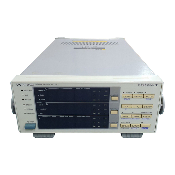
Front Panel, Rear Panel and Top View Front Panel WT110 (253401) WT130 (253502, 253503) 7-segment display 7-segment display function/unit/element display function/unit display operation keys page 2-3 operation keys page 2-2 handle handle power switch ventilation slot power switch ventilation slot... -
Page 20: Operation Keys And Function/Element Display
Operation Keys and Function/Element Display WT110 (253401): Operation keys and function display HOLD Indicators for operation conditions Shows sampling, voltage/current overrange and Keeps the displayed value, and the HOLD measurement mode indicator will light up. Pressing once again will result in canceling HOLD... - Page 21 2.2 Operation Keys and Function/Element Display WT130 (253502, 253503): Operation keys and function / element display Indicators for operation conditions HOLD Shows sampling, voltage/current overrange and Keeps the displayed value, and the HOLD measurement mode indicator will light up. Pressing once again will result in canceling HOLD V RANGE Shows the voltage range setting menu (page 4-4)
-
Page 22: Displays In Case Of Overrange/Error During Measurement
Displays in case of Overrange / Error during Measurement Overrange display Overrange occurs when the measured voltage or current exceeds 140% of the rated measurement range. In that case the range will automatically be increased, however up to 140% of the maximum range. When this level is exceeded, the overrange display wil appear, which looks as follows. -
Page 23: Usage Precautions
When unplugging the power cord from the power outlet, always hold the plug and pull it, never pull the cord itself. If the power cord becomes damaged, contact your nearest YOKOGAWA representative. Addresses may be found on the back cover of this manual. -
Page 24: Installing The Instrument
Desktop Place the instrument in a horizontal position or tilted using the stand, as shown below. • WT110 (253401) When installing using the handle, verify that the handle is in a fixed position. While pulling the handle approx. 2 to 3mm from the turning axes on both side, slowly turn the handle until it slips into the fixed position. - Page 25 751534-J3 • Mounting procedure 1. Remove the handle. For the WT110, turn the handle to position 8 (refer to the picture on the previous page) and remove the handle by pulling it approx. 10mm from the turning axes on both sides. For the WT130, remove the handle by first removing the covers of the handle, and then unfastening the screws.
-
Page 26: Wiring Precautions
Wiring Precautions • To prevent hazards, make sure to apply a ground protection before WARNING connecting the object being measured. • Always turn OFF the power to the object being measured before connecting it to the instrument. Never connect or disconnect the measurement lead wires from the object while power is being supplied to it, otherwise a serious accident may result. -
Page 27: Wiring The Measurement Circuit
Wiring the Measurement Circuit • When applying a current to be measured directly to the input terminals of WARNING the instrument, disconnect the input cable of the external sensor. A voltage might be generated by the external sensor input terminal when connected. •... - Page 28 3.4 Wiring the Measurement Circuit Wiring diagram for three-phase, three-wire system (253502, 253503) ± SOURCE LOAD SOURCE ± LOAD ± ± ± ± ± Input terminal Input terminal (ELEMENT1) (ELEMENT3) ± Wiring diagram for three-phase, four-wire system (253503) SOURCE LOAD ±...
-
Page 29: Wiring The Measurement Circuit When Using External Pt/Ct
Wiring the Measurement Circuit when Using External PT/CT • When using an external CT, do not allow the secondary side of the CT to WARNING go open-circuit while power is supplied, otherwise an extremely high voltage will be generated on the secondary side of the CT. •... - Page 30 3.5 Wiring the Measurement Circuit when Using External PT/CT Wiring diagram for three-phase, three-wire system with PT and CT connected (253502, 253503) SOURCE LOAD ± ± ± ± Input terminal Input terminal (ELEMENT1) (ELEMENT3) Wiring diagram for three-phase, four-wire system with PT and CT connected (253503) SOURCE LOAD...
-
Page 31: Wiring The Measurement Circuit When Using The External Sensor
Wiring the Measurement Circuit when Using the External Sensor • Use an external sensor that is enclosed in a case which has sufficient WARNING withstand voltage against the voltages to be measured. Use of bare sensor may cause an electric shock if the sensor is touched accidentally. •... - Page 32 3.6 Wiring the Measurement Circuit when Using the External Sensor In cases where the maximum current of the object under measurement exceeds 20A, measurement becomes possible by connecting an external sensor. The range for external sensor input is either 2.5/5/10V or 50/100/200mV. Either range is available as an option. In the following wiring diagrams, the external shunt is grounded.
- Page 33 3.6 Wiring the Measurement Circuit when Using the External Sensor Wiring diagram for three-phase, three-wire system with external shunt connected (253502, 253503) SOURCE LOAD ± OUT L OUT H ± OUT H OUT L ± ± Ext. sensor input Ext. sensor input terminal (EXT) terminal (EXT) ±...
-
Page 34: Connecting The Power Supply
• Be sure to connect the protective grounding to prevent an electric shock WARNING before turning on the power. • Be sure to use the power supply cord provided by YOKOGAWA. The mains power plug can only be plugged into an outlet with a protective grounding terminal. -
Page 35: Turning The Power On/Off
Turning the Power ON/OFF Item to be Checked before Turning ON the Power • Check that the instrument is installed correctly (refer to section 3.2, page 3-2). • Check that the power cord is connected properly (refer to section 3.7, page 3-12). Location of the Power Switch The power switch is located in the lower left corner of the front panel. - Page 36 Display A Display B Display C Power switch No display All LED`s light up Extinguish (For 253502 (Model) No display (For WT110) Display differs depending on specs (Version) No display and options. (Only for/EX1, EX2) (E-2) (Only for/HRM option) (For/DA option)
-
Page 37: Selecting The Wiring Method (For Wt130)
3Φ4W 3V3A *Shows the operation panel of the WT130. For the differences between WT110 and WT130, refer to section 2.2, page 2-2, 2-3 Explanation Wiring Method The wiring method is selectable by pressing the WIRING key. The selectable wiring method depends on the model. -
Page 38: Improving The Measurement Accuracy
3.10 Improving the Measurement Accuracy Recommended Wiring Method The instrument is designed so that voltage input impedance is high and current input impedance is low to reduce the effect of power loss on measurement accuracy. Voltage input impedance : Approx. 2MΩ (all ranges), with a capacitance of appox. 15pF connected in parallel Current input impedance : Approx. -
Page 39: Selecting The Measurement Mode
SCALING FILTER STORE RECALL HARMONICS 3Φ4W 3V3A *Shows the operation panel of the WT130. For the differences between WT110 and WT130, refer to section 2.2, page 2-2, 2-3 Operating Procedure V RANGE V RANGE V RANGE MODE MODE SHIFT SHIFT... - Page 40 4.1 Selecting the Measurement Mode Typical Waveform Types and Differences in Measured Values between Measurement Modes Measurement Mean Mean-value Linear mode rectification value value averaging Name Display — V MEAN Waveform Sinewave · Ep π 2π π Half-wave rectification π π...
-
Page 41: Turning The Filter On/Off
3Φ4W 3V3A *Shows the operation panel of the WT130. For the differences between WT110 and WT130, refer to section 2.2, page 2-2, 2-3 Operating Procedure • Perform operations following the thick line in the below menu. • Press the ENTER key to confirm the selection or setting. -
Page 42: Selecting The Measurement Range In Case Of Direct Input
3Φ4W 3V3A *Shows the operation panel of the WT130. For the differences between WT110 and WT130, refer to section 2.2, page 2-2, 2-3 Operating Procedure • Perform operations following the thick line in the below menu. • Press the ENTER key to confirm the selection or setting. - Page 43 4.3 Selecting the Measurement Range in case of Direct Input Range up: A higher range is selected immediately if the instantaneous input voltage or current exceeds approx. 300% of the rated value during sampling. If the meaured voltage or current exceeds 110% of the rated value, a higher range will be selected at the end of the current measurement cycle.
-
Page 44: Setting The Scaling Value When External Pt/Ct Is Used
3Φ4W 3V3A *Shows the operation panel of the WT130. For the differences between WT110 and WT130, refer to section 2.2, page 2-2, 2-3 Operating Procedure • Perform operations following the thick line in the below menu. • Press the ENTER key to confirm the selection or setting. - Page 45 • F : Sets the power value on display C In case of the WT110, pressing the ENTER key after setting P, C and F respectively will end this scaling setting. In case of the WT130, selecting End at the input element menu will end this scaling setting.
-
Page 46: Selecting The Measurement Range And Setting The Scaling Value When External Sensor Is Used (Option)
3Φ4W 3V3A *Shows the operation panel of the WT130. For the differences between WT110 and WT130, refer to section 2.2, page 2-2, 2-3 Operating Procedure • Perform operations following the thick line in the below menu. • Press the ENTER key to confirm the selection or setting. - Page 47 Setting the Scaling Value The procedure to set the scaling values depends on the setting format (previous setting). The setting ranges from 0.001 to 1000. The initial value is 50.00. In case of the WT110, the scaling value is set at display C.
-
Page 48: Using The Averaging Function
3Φ4W 3V3A *Shows the operation panel of the WT130. For the differences between WT110 and WT130, refer to section 2.2, page 2-2, 2-3 Operating Procedure • Perform operations following the thick line in the below menu. • Press the ENTER key to confirm the selection or setting. - Page 49 4.6 Using the Averaging Function Explanation About the Averaging Function This function performs exponential averaging or moving averaging on measurement values. When the displayed values are unsteady due to big fluctuations in power source or load, or due to the low frequency of the input signal, this function is useful to stabilize the displayed values for easier reading.
-
Page 50: Using The Four Arithmetical Operation Function (Applies To Wt110/Wt130 With Rom Version 2.01 Or Later)
3Φ4W 3V3A *Shows the operation panel of the WT130. For the differences between WT110 and WT130, refer to section 2.2, page 2-2, 2-3 Operating Procedure • Perform operations following the thick line in the below menu. • Press the ENTER key to confirm the selection or setting. - Page 51 4.7 Using the Four Arithmetical Operation Function (Applies to WT110/WT130 with ROM Version 2.01 or later) Application Example • Power summation : Displays the result of display A + display B. Computation example : Display A Display B Display C...
- Page 52 4.7 Using the Four Arithmetical Operation Function (Applies to WT110/WT130 with ROM Version 2.01 or later) • Useful when setting a function other than VA (apparent power) for display A and displaying VA on display C. : Displays the result of display A × display B.
-
Page 53: Computing The Crest Factor (Applies To Wt110/Wt130 With Rom Version 2.01 Or Later)
3Φ4W 3V3A *Shows the operation panel of the WT130. For the differences between WT110 and WT130, refer to section 2.2, page 2-2, 2-3 Operating Procedure • Perform operations following the thick line in the below menu. • Press the ENTER key to confirm the selection or setting. -
Page 54: Computing The Efficiency (Applies To Wt130 With Rom Version 2.01 Or Later)
3Φ4W 3V3A *Shows the operation panel of the WT130. For the differences between WT110 and WT130, refer to section 2.2, page 2-2, 2-3 Operating Procedure • Perform operations following the thick line in the below menu. • Press the ENTER key to confirm the selection or setting. - Page 55 4.9 Computing the Efficiency (Applies to WT130 with ROM Version 2.01 or later) Wiring Method and Computing Equation • When the input and output are both two-wire Select 1Φ2W, 1Φ3W, or 3Φ3W for the wiring method for the three-phase three-wire system 253502) and 1Φ2W for the wiring method for the three-phase four-wire system (253503).
-
Page 56: Measuring/Displaying Voltage, Current And Active Power
3Φ4W 3V3A *Shows the operation panel of the WT130. For the differences between WT110 and WT130, refer to section 2.2, page 2-2, 2-3 Operating Procedure 1 Selecting the Display Function Select either V (voltage), A (current) or W (power) by pressing the FUNCTION key. - Page 57 5.1 Measuring/Displaying Voltage, Current and Active Power Explanation Continuous Maximum Allowable Input • Voltage : peak voltage is 1.5kV, or the RMS value is 1.0kV, whichever is less. • Current : peak current is 100A or the RMS value is 30A, whichever is less. In case of external sensor input, the peak value is 5 times the measurement range or less.
-
Page 58: Measuring/Displaying Frequency
3Φ4W 3V3A *Shows the operation panel of the WT130. For the differences between WT110 and WT130, refer to section 2.2, page 2-2, 2-3 Operating Procedure 1 Selecting the Display Function Select either V Hz (voltage frequency) or A Hz (current frequency) by pressing the FUNCTION key of display C. -
Page 59: Measuring/Displaying Four Arithmetic Operation Value, Crest Factor And Peak Value
3Φ4W 3V3A *Shows the operation panel of the WT130. For the differences between WT110 and WT130, refer to section 2.2, page 2-2, 2-3 Operating Procedure 1 Selecting the display Function Select either (four arithmetical operations, crest factor), (voltage peak value) or (current peak value) by pressing the FUNCTION key. -
Page 60: Computing/Displaying Apparent Power, Reactive Power And Power Factor
3Φ4W 3V3A *Shows the operation panel of the WT130. For the differences between WT110 and WT130, refer to section 2.2, page 2-2, 2-3 Operating Procedure 1 Selecting the Display Function Select either VA (apparant power), var (reactive power) or PF (power factor) by pressing the FUNCTION key of display A or B. -
Page 61: Computing/Displaying The Phase Angle
3Φ4W 3V3A *Shows the operation panel of the WT130. For the differences between WT110 and WT130, refer to section 2.2, page 2-2, 2-3 Operating Procedure 1 Selecting the Display Function Select deg (phase angle) by pressing the FUNCTION key of display B. -
Page 62: Chapter 7 Integration
Integrator Functions Active power integration and current integration can be carried out. All measurement values (and computed values) can be displayed, even when integration is in progress, except for the integrated values (watt hour or ampere hour) and integration elapsed time. Since integrated values of negative polarity can be also displayed, the consumed watt hour (ampere hour) value of the positive side and the watt hour value returning to the power supply of the negative side (ampere hour: only when the measurement mode is DC), can be displayed seperately. - Page 63 7.1 Integrator Functions Continous Integration Mode (Repeat Integration) • Integration starts: • after having pressed the START key; • when the preset time for integration is reached, the integrated value and integration elapsed time are reset automatically and restarted immediately. •...
- Page 64 7.1 Integrator Functions Display Resolution during Integration The display resolution for integrated values is 100000 counts. The decimal point shifts automatically since the integrated value increases in accordance with the elapsed time. The decimal point shifting timing is determined automatically according to the selected voltage and current measuring ranges.
-
Page 65: Setting Integration Mode And Integration Timer
3φ4W 3V3A *Shows the operation panel of the WT130. For the differences between WT110 and WT130, refer to section 2.2, page 2-2, 2-3 Operating Procedure • Perform operations following the thick line in the below menu. • Press the ENTER key to confirm the selection or setting. -
Page 66: Displaying Integrated Values
3φ4W 3V3A *Shows the operation panel of the WT130. For the differences between WT110 and WT130, refer to section 2.2, page 2-2, 2-3 Operating Procedure 1 Selecting the Display Function Pressing the FUNCTION key on display A will select TIME (integration elapsed time). - Page 67 7.3 Displaying Integrated Values Explanation Maximum Reading of the Display and Units Maximum reading • Integrated value :999999 (–99999 in case of minus display) • Integration elapsed time :999.59 • Units : Wh (power integration : watt hour value), Ah(current integration : ampere hour value) •...
-
Page 68: Precautions Regarding Use Of Integrator Function
Precautions Regarding Use of Integrator Function Relation between Integration Hold and the START/STOP key When the HOLD key is pressed, the display and communication output of the integrated results is being held while integration continues. The relation between this hold function and the START/STOP key is as follows. - Page 69 7.4 Precautions Regarding Use of Integrator Function Backup During Power Failures • If there is a power failure while integration is in progress, the integrated value and integration elapsed time will be backed up. When the power is restored, the display will show the integrated results up to the time the power failure occurred.
-
Page 70: Harmonic Analysis Function
After having set the harmonic analysis function to ON, the harmonic component of voltage, current, or active power, will be analyzed and displayed for one of the input elements (not applicable for the WT110). Depending on the setting of the display function, the display changes as follows. -
Page 71: Averaging Function
8.1 Harmonic Analysis Function Holding the Display When you use the display hold function and change the order or display function while the harmonic analysis function is ON, you can display the harmonic data analyzed at the corresponding time. Updating the Displayed Data The display can be updated in the same way as for normal measurement. -
Page 72: Setting The Element, Pll Source And Harmonic Distortion Method
3Φ 4W 3V3A *Shows the operation panel of the WT130. For the differences between WT110 and WT130, refer to section 2.2, page 2-2, 2-3 Operating Procedure • Perform operations following the thick line in the below menu. • Press the ENTER key to confirm the selection or setting. - Page 73 Setting the Element Only one input element should be set for harmonic analysis. The initial value is EL1. At the WT110 the element setting menu does not appear. • EL1 : Element 1 will be used for analysis; • EL2 : Element 2 will be used for analysis; In case of the 253502, this menu will not be shown;...
-
Page 74: Switching The Harmonic Analysis Function On/Off
3Φ4W 3V3A *Shows the operation panel of the WT130. For the differences between WT110 and WT130, refer to section 2.2, page 2-2, 2-3 Operating Procedure • Perform operations following the thick line in the below menu. • Press the ENTER key to confirm the selection or setting. -
Page 75: Setting The Harmonic Order And Displaying The Results Of Harmonic Analysis
3Φ4W 3V3A *Shows the operation panel of the WT130. For the differences between WT110 and WT130, refer to section 2.2, page 2-2, 2-3 Operating Procedure The following operations assume that the harmonic analysis function is turned ON. Setting the Harmonics Order 1. - Page 76 8.4 Setting the Harmonic Order and Displaying the Results of Harmonic Analysis Displaying the Results of Harmonic Analysis Depending on the setting of display function of display B and C, the analyzed items will appear on the display as follows. In the following explanation a maximum of 50 analysis orders is assumed.
- Page 77 8.4 Setting the Harmonic Order and Displaying the Results of Harmonic Analysis Computation Equation Vk, Ak, Wk :Each component of 1st to 50th order of voltage, current and active power; :Analysis order :Maximum order. The maximum order depends on the fundamental frequency of the input set as the PLL source.
-
Page 78: Storing/Recalling Measured Data
3Φ4W 3V3A *Shows the operation panel of the WT130. For the differences between WT110 and WT130, refer to section 2.2, page 2-2, 2-3 Operating Procedure • Perform operations following the thick line in the below menu. • Press the ENTER key to confirm the selection or setting. - Page 79 9.1 Storing/Recalling Measured Data Explanation Storing Measured Data (Storing into Internal Memory) The number of blocks which can be stored into the internal memory is as follows. Model In case of normal measurement In case of harmonic analysis 253401 600 Blocks 30 Blocks 253402 300 Blocks...
- Page 80 9.1 Storing/Recalling Measured Data Recalling Measured Data (Retrieving Data from the Internal Memory) After displaying data stored in the internal memory on the panel, you can use all display functions and carry out integration and display these data. Furthermore, by using the communication function, data can be output.
-
Page 81: Storing/Recalling Set-Up Parameters
3Φ3W 3V3A *Shows the operation panel of the WT130. For the differences between WT110 and WT130, refer to section 2.2, page 2-2, 2-3 Operating Procedure • Perform operations following the thick line in the below menu. • Press the ENTER key to confirm the selection or setting. - Page 82 9.2 Storing/Recalling Set-up Parameters Explanation Storing Set-up Parameters Stores the current set-up parameters which consist of the following. Four destinations (FiLE1/ FilE2/FiLE3/FiLE4) are available. Measurement range, measurement mode, scaling settings, averaging settings, filter settings, integration settings, harmonic settings, plotter output settings, store/recall settings, and communication settings.
-
Page 83: Remote Control And D/A Output Connector (Optional)
(Output) (Output) :0 to 0.4V(8mA) (Output) (Output) :2.4 to 5V(–400µA) (Output) (Output) /CMP specifications (for WT110/130: 253401, 253502, 253503) remote control, 4 channel D/A output, 4 channel comparator output Pin No. Signal Pin No. Signal DIGITAL COM DIGITAL COM (Input) -
Page 84: Remote Control (Optional)
10.2 Remote Control (optional) Controlling Integration To control integration, apply timing signals according to the timing chart below. Start Stop Reset Start Stop 5ms min. EXT START 5ms min. EXT STOP 5ms min. EXT RESET Approx. Approx. Approx. Approx. 15ms 15ms 15ms 15ms... -
Page 85: D/A Output (Optional)
3Φ4W 3V3A *Shows the operation panel of the WT130. For the differences between WT110 and WT130, refer to section 2.2, page 2-2, 2-3 Operating Procedure • Perform operations following the thick line in the below menu. • Press the ENTER key to confirm the selection or setting. - Page 86 10.3 D/A Output (optional) • Setting Preset Integration Time Selecting preset integration time (Display C) Preset time setting RESET (Display A) SHIFT INTEG SET hour ENTER ENTER Up/down cursor shift SHIFT Explanation D/A Output Voltage, current, active power, apparent power, reactive power, power factor, phase angle, harmonic analysis data and integrated data values will be output as a 5V FS analog voltage.
- Page 87 – – – – (D/A output 0V; no further elements can be set) *1 For details concerning the positive value of the ampere hour, refer to page 7-3. *2 Available on WT110/WT130 with ROM version 2.01 or later. • Setting the element (corresponds to colum B in the operating procedure) •...
- Page 88 10.3 D/A Output (optional) Relation between the output item and the D/A output voltage • Frequency D/A output Approx. 7.5V 5.0V 2.5V 0.5V 0.2V Displayed value [Hz] • Integrated value D/A output Approx. 7.0V 5.0V In case of 140% of rated value input In case of rated value input...
-
Page 89: Comparator Function (Optional)
10.4 Comparator Function (optional) When the instrument is equipped with option /CMP you can compare the measured/computed/ integrated/analysis values with previously set limits and these results can be output by contact relay. Contact Relay Output This instrument is equipped with four contact relays (4 ch) as follows. If the relay is not operating, the NC (Normally Closed) contact is closed. - Page 90 10.4 Comparator Function (optional) Dual Mode This mode allows you to combine the limit values of two relays (e.g. the upper value (Hi) and the lower value (Lo)) to determine the contact status. The four relays will be fixed as two pairs of ch1 &...
-
Page 91: Setting The Comparator Mode (Optional)
3Φ4W 3V3A *Shows the operation panel of the WT130. For the differences between WT110 and WT130, refer to section 2.2, page 2-2, 2-3 Operating Procedure • Perform operations following the thick line in the below menu. • Press the ENTER key to confirm the selection or setting. -
Page 92: Setting The Comparator Limit Values (Optional)
3Φ4W 3V3A *Shows the operation panel of the WT130. For the differences between WT110 and WT130, refer to section 2.2, page 2-2, 2-3 Operating Procedure • Perform operations following the thick line in the below menu. • Press the ENTER key to confirm the selection or setting. - Page 93 10.6 Setting the Comparator Limit Values (optional) • Setting the Comparator Limit Values in case of Harmonic Anaiysis Selecting the comparator function (Display C) SETUP OUTPUT SHIFT (Display C) ENTER ENTER Relay setting Setting type of limit Setting limit value Setting exponent (Display C) (Display A)
- Page 94 – – – – (no data) *1 For details concerning the positive value of the ampere hour, refer to page 7-3. *2 Available on WT110/WT130 with ROM version 2.01 or later. • Setting the element (corresponds to column B in the operating procedure) •...
- Page 95 Therefore, before setting, verify the maximum order (chapter 15) and the fundamental frequency of the object of measurement. • Setting the limit value No element setting is available on the WT110. : 0.000 to ±9999 Setting range Initial setting ch1 : V (type) : 1 (element) : 600.0 (value) : E+0 (exponent) [ 600V voltage limit of...
-
Page 96: Comparator Display (Optional)
3Φ4W 3V3A *Shows the operation panel of the WT130. For the differences between WT110 and WT130, refer to section 2.2, page 2-2, 2-3 Operating Procedure • Perform operations following the thick line in the below menu. • Press the ENTER key to confirm the selection or setting. - Page 97 10.7 Comparator Display (optional) Explanation Comparator Display Function This function allows you to verify the set limits together with measurement/computation/ analysis data on the display when using the comparator function. The display is as follows, depending on whether the comparator function is set to single or dual mode. •...
-
Page 98: Turning The Comparator Function On/Off (Optional)
3Φ4W 3V3A *Shows the operation panel of the WT130. For the differences between WT110 and WT130, refer to section 2.2, page 2-2, 2-3 Operating Procedure • Perform operations following the thick line in the below menu. • Press the ENTER key to confirm the selection or setting. -
Page 99: Outputting To An External Plotter/Printer
3Φ4W 3V3A *Shows the operation panel of the WT130. For the differences between WT110 and WT130, refer to section 2.2, page 2-2, 2-3 Operating Procedure • Perform operations following the thick line in the below menu. • Press the ENTER key to confirm the selection or setting. - Page 100 • Setting the Element (Column B) One of the following should be set. The output items corresponding to the set element will then be printed out on an external plotter. The initial value is 1. In case of the WT110, this setting is always 1.
- Page 101 10.9 Outputting to an External Plotter / Printer Note • When the output items are to be sent by communication interface and they are set to V, A, P or dEG, these items are then output. When the output item to be sent by communication is set to ALL, not only the V and A data are output, but P and dEG data as well.
- Page 102 10.9 Outputting to an External Plotter / Printer Output example of set-up parameters Output example of harmonic analysis data WT110/130 Setup Lists Version : 1.11 Voltage range Model : M/253503/HRM Model : 253503-C1/EX1/HRM/CMP V Range : 15 V Current range A Range : 0.5A...
-
Page 103: Gp-Ib Interface
11.1 Using the GP-IB Interface This instrument is equipped with a GP-IB interface in accordance with your preference. This interface permits remote control from a controller such as a personal computer, and output of various data. Overview of the GP-IB Interface The table below shows functions that are available in each mode. -
Page 104: Responses To Interface Messages
11.2 Responses to Interface Messages Responses to Interface Messages IFC (Interface Clear) Unaddresses talker and listener. REN (Remote Enable) Transfers the instrument from local control to remote control. GTL (Go To Local) Transfers the instrument from remote control to local control. SDC (Selective Device Clear), DCL (Device Clear) Cleasrs GP-IB input/output buffer, and resets an error. -
Page 105: Status Byte Format (Before The Ieee488.2-1987 Standard)
11.3 Status Byte Format (before the IEEE 488.2-1987 Standard) DIO 5 DIO 8 DIO 7 DIO 6 DIO 4 DIO 3 DIO 2 DIO 1 Integration ERROR STORE/ OVER Syntax Integration Computation BUSY RECALL ERROR BUSY Integration Busy (DIO 8) This bit is set to “1”... -
Page 106: Parameters And Error Codes
MEM : Data number in case of recalling (Efficiency, crest factor, and the results of four arithmetic operations can be output on WT110/WT130 with ROM version 2.01 and later. However, different instruments have different restrictions on the output of these parameters.) h4: Element 4: ∑... - Page 107 • When the frequency is set by either of the following methods, only one value is measured, and that value will be output. - by panel keys : by the FUNCTION key and ELEMENT key of display C (except WT110) - by communication command : by the “DC” or “EC” command.
- Page 108 Line 4 Line 5 Frequency Display C Terminator Line 6 Terminator Default Output Format in case Integration Measurement WT110 (253401) Data Line 1 (The data number will only be output in case of recall) Terminator number Line 2 W1 data...
- Page 109 11.4 Output Format for Normal Measured/Computed Data, Harmonic Analysis Data, Set-up Parameters and Error Codes Output Format of Harmonic Analysis Data Data Format Harmonic analysis data normally consists of a 8-byte header and 11 bytes of data Header Data Header Section The header section consists of 8 bytes (h1 to h8).
- Page 110 11.4 Output Format for Normal Measured/Computed Data, Harmonic Analysis Data, Set-up Parameters and Error Codes Output Format The output format depends on the selected output items which can be selected by the “OH” command. In case of voltage and current All computed values of Line 1 harmonic distortion...
-
Page 111: Setting The Address/Addressable Mode
3Φ4W 3V3A * Shows the operation panel of the WT130. For the differences between WT110 and WT130, refer to section 2.2, page 2-2, 2-3 Operating Procedure • Perform operations following the thick line in the below menu. • Press the ENTER key to confirm the selection or setting. -
Page 112: Setting The Output Items
3Φ4W 3V3A * Shows the operation panel of the WT130. For the differences between WT110 and WT130, refer to section 2.2, page 2-2, 2-3 Operating Procedure • Perform operations following the thick line in the below menu. • Press the ENTER key to confirm the selection or setting. - Page 113 ), – – – – (no output) *1 For details regarding the positive ampere hour, refer to page 7-3. *2 Available on WT110/WT130 with ROM version 2.01 or later. • Setting the element (corresponds to column B in the operating procedure) The element setting depends on the model and is as follows.
-
Page 114: Commands (Before The Ieee488.2-1987 Standard)
• If commands relating to options are used on instruments which do not have the options installed, "Error 11" is displayed. Also, there are no responses to inquiries. • "MATH" is available on WT110/WT130 with ROM version 2.01 or later. 11-12... -
Page 115: Chapter 12 Rs-232-C Interface
12.1 Using the RS-232-C Interface This instrument is equipped with a RS-232-C interface in accordance with your preference. This interface permits remote control from a controller such as a personal computer, and output of various data. Overview of the RS-232-C Interface The table below shows functions that are available in each mode. -
Page 116: Connecting The Interface Cable
12.2 Connecting the Interface Cable When connecting this instrument to a personal computer, make sure that the handshaking method, data transmission rate and data format selected for the instrument match those selected fro the computer. For details, refer to the following pages. Also make sure that the correct interface cable is used. - Page 117 12.2 Connecting the Interface Cable Table of RS-232-C Standard Signals and their JIS and CCITT Abbreviations Abbreviations Pin No. Name RS-232-C CCITT (25-pin connector) AA(GND) Protective ground AB(GND) Signal ground BA(TXD) Transmitted data BB(RXD) Received data CA(RTS) Request to send CB(CTS) Clear to send CC(DSR)
-
Page 118: Setting The Mode, Handshaking Method, Data Format And Baud Rate
3Φ4W 3V3A *Shows the operation panel of the WT130. For the differences between WT110 and WT130, refer to section 2.2, page 2-2, 2-3 Operating Procedure • Perform operations following the thick line in the below menu. • Press the ENTER key to confirm the selection or setting. - Page 119 12.3 Setting the Mode, Handshaking Method, Data Format and Baud Rate Explanation Mode Setting Refer to page 12-1 for more details. Handshaking To use an RS-232-C interface to transfer data between this instrument and a computer, it is necessary to use certain procedures by mutual agreement to ensure the proper transfer of data. These procedures are called “handshaking”.
- Page 120 12.3 Setting the Mode, Handshaking Method, Data Format and Baud Rate Data Format The RS-232-C interface of this instrument performs communications using start-stop synchronization. In start-stop synchronization, one character is transmitted at a time. Each character consists of a start bit, data bits, a parity bit, and a stop bit. Refer to the figure below. Level returns to idle state (dotted line) or 1 character...
-
Page 121: Format And Commands Of Output Data (Brefore The Ieee488.2-1987 Standard)
12.4 Format and Commands of Output Data (before the IEEE488.2-1987 Standard) Output Format The format of output data is the same as for the GP-IB interface. Refer to page 11-4 for more details. Commands The commands used for the RS-232-C interface are identical to those used for the GP-IB interface, except for the following commands. -
Page 122: Back-Up Of Set-Up Parameters
PT/CT scaling value External sensor scaling value Averaging ON/OFF Averaging type Averaging sample number/attenuation constant Computing Equation of MATH function (applies to WT110/WT130 with ROM version 2.01 or later) Display function/element for each display Integration mode Integration timer preset time... -
Page 123: Initializing Set-Up Parameters
• Be careful since measurement data will be lost when initializing. However, measurement data or set-up parameters stored in the internal memory will be kept. • "MATH computing equation" applies to WT110/WT130 with ROM version 2.01 or later. 13-2 IM 253401-01E... -
Page 124: Adjustments
Required Equipments AC Voltage/Current Standard (0.02%, 30 to 300V, 1 to 10A/60Hz) recommended: Yokogawa 9100 or 2558 (if you want to carry out adjustments with an accuracy higher than the one 2558 is providing, fine adjust the output using the Digital Multi Meter (DMM) 1271) DMM (0.5%) - Page 125 14.1 Adjustments 4 Press the ENTER key after the value on display C stabilizes. (Even in a stabilized condition, drifting within ± 2 digits limit may occur.) 5 Display B will change to “300.0” V. 6 Set the output voltage of the standard to 300.0V. 7 Press the ENTER key after the value on display C stabilizes.
- Page 126 14.1 Adjustments Adjusting the D/A Output • Preparations 1 Connect the pin No. of the output connector corresponding to the channel to be adjusted to the H terminal of the DMM, and connect pin No. 12 and 24 of the output connector to the L terminal.
-
Page 127: Calibration
AC Voltage/Current Standard recommended: Yokogawa 2558 or 9100 (up to 400Hz) or Fluke 5200A + 5215A or 5200A + 5220A Digital Power Meter recommended: Yokogawa WT2000 or 2531 2ch Synchronizer recommended: Yokogawa FG120 Calibration of DC Voltage, Current and Power Wiring Connect the DC voltage and DC current standard as follows. - Page 128 14.2 Calibration • External sensor input (equipped with option /EX2) DC voltage standard ± (A) ± (A) ± (A) Calibration Regarding the combination of voltage and current ranges, we recommend applying the following. • Test the current ranges with the voltage range set to 150V; •...
- Page 129 14.2 Calibration Calibration of AC Voltage, Current and Power Wiring Connect the Digital Power meter, Synchronizer and the AC voltage and AC current standard as follows. • Direct input EUT:Equipment under test AC voltage ± standard ± Synchronizer ± ± ±...
- Page 130 14.2 Calibration • External sensor input (equipped with option /EX2) Change as follows for wiring currents only. AC voltage Synchronizer standard ± (A) ± (A) ± (A) Preparation Set the frequency of the AC voltage standard and of each channel of the synchronizer to 60Hz. Then, while not exceeding the maximum values of the external synchronization inputs of the voltage and current standard, rise the output level of the synchronizer until the standards are synchronized.
- Page 131 14.2 Calibration Calibration of D/A Output Preparation 1 Connect the AC voltage standard to the voltage terminal of this instrument. The wiring method is the same as when adjustments are carried out (see page 14-3). However, calibration of the WT130 can also be carried out when only element 1 is connected. 2 Set the D/A output of this instrument to V1 for each channel.
- Page 132 14.2 Calibration Calibration of the Harmonic Analysis Function Connection Use the same instruments as in case of AC power measurement and connect them in the same way (refer to page 14-6 and 14-7). Preparation 1 Set the voltage range of this instrument to 15V, and the current range to 1A. 2 Turn the harmonic analysis function ON.
-
Page 133: In Case Of Malfunctioning
14.3 In Case of Malfunctioning Check These Items First If the instrument does not operate properly even if the actions given in the table below are performed, contact your nearest sales representative. Addresses may be found on the back cover of this manual. -
Page 134: Error Codes And Corrective Actions
14.4 Error Codes and Corrective Actions Error Codes for Operation and Measurement Error Code Description Corrective Action Reference page Received a command not used by this Check for error in the command 11-12 instrument. sent. Parameter value specified is outside the Correct the value. - Page 135 14.4 Error Codes and Corrective Actions Power factor exceeded "2" during measurement of power factor. "PFErr" was displayed at the end of power 6-1, 6-2 factor computation during measurement of phase angle. Input level was too low or below measurement range during measurement of frequency.
-
Page 136: Replacing The Fuse (For Wt130)
5 Insert a new fuse into the holder, then install the holder in place. Note The fuse used in the WT110 can not be replaced by the user, because of the fuse inside the case. If you believe the fuse is blown, please contact your nearest YOKOGAWA representative listed on the back cover of this manual. -
Page 137: Chapter 15 Specifications
±(0.5% of rdg + 0.5% of rng) 20kHz < f ≤ 50kHz : ±(0.8% of rdg + 0.8 % of rng) YOKOGAWA calibration system. ±[{0.25 × (f-10)}% of rdg] ±[{0.15 × (f-10)}% of rdg] * DC: ±0.2% of range is added if the 0.5/1 A range is selected. -
Page 138: Computing Functions
Σ Σ =var +var Measurement data –1 cos ( Σ Σ Number of data that can be stored: WT110 (253401): 600 blocks ϕ × WT130 (253502): 300 blocks WT130 (253503): 200 blocks =1,2,3 =1,2,3 ) –W –1 cos ( Each block has following data:... -
Page 139: External Input (Optional)
240V) WT110:20 VA maximum; WT130: 32 VA maximum (Power supply : 100V) WT110:Approx. W × H × D : 213 × 88 × 350 (mm), External dimensions: 8-3/8 × 3-1/2 × 13-3/4 (inch) WT130:Approx. W × H × D : 213 × 132 × 350 (mm), 8-3/8 ×... -
Page 140: External Dimensions
Chapter 15 Specifications 15.15 External Dimensions WT110(253401) Unit:mm Rear JIS rack mount Protruding from rack Protruding from rack EIA rack mount Protruding from rack Protruding from rack Unless other wise specified, tolerance is ±3% (However, tolerance is ±0.3mm when below 10mm) - Page 141 Chapter 15 Specifications WT130(253502, 253503) Unit:mm Rear JIS rack mount Protruding from rack Protruding from rack EIA rack mount Protruding from rack Protruding from rack Unless other wise specified, tolerance is ±3% (However, tolerance is ±0.3mm when below 10mm) 15-5 IM 253401-01E...
- Page 142 • Parameter error 12 will occur if “m” is set to an 8 :256 illegal value. Query AC? <terminator> • The output format of the WT110/130 is the Example same for m=0 or 1. Description • Parameter error 12 will occur if “m” is set to an illegal value.
- Page 143 26 :positive ampere hour (Ah+) about the current setting. 27 :negative ampere hour (Ah–) Syntax EA m <terminator> * Applies to WT110/WT130 with ROM “m” indicates element. version 2.01 or later m=1 :Element 1 • in case of harmonic analysis...
- Page 144 Appendix 1.1 Commands Syntax EC m <terminator> • Integration cannot be started when the harmonic “m” indicates element. analysis function is in progress; error 16 will occur. • While recalling or storing is in progress, m=1 :Element 1 execution error 19 will occur. 2 :Element 2 (for model 253503 only) 3 :Element 3 (for WT130 only) HE/HE?
- Page 145 Query MT?<terminator> Query When CM0 is set: Example KV? <terminator> Description • This command applies to WT110/WT130 with KA? <terminator> ROM version 2.01 or later. KW? <terminator> When CM1 is set: OA/OA? Sets D/A output items/inquires about the KV1? <terminator>...
- Page 146 26 :Positive ampere-hour (Ah+) 11 Command error 27 :Negative ampere-hour (Ah–) 12 Parameter error * Applies to WT110/WT130 with ROM 13 Attempted to change settings which cannot version 2.01 or later be changed while integration was in “m3” indicates element, and must be set within progress.
- Page 147 Appendix 1.1 Commands • Select mode (OFD2) is validated when the OF 6 :(GA) outputs current analysis value command is executed if “m” is set to “0” and relative harmonic content as (default for normal measurement) or “1” numerical value (default for integration).
- Page 148 1 as a dummy. 27 :Negative ampere-hour (Ah–) • “PF”, “VTHD” and “ATHD” are not related to * Applies to WT110/WT130 with ROM any order, so in case the OYH command is version 2.01 or later used, set 1 as a dummy.
- Page 149 Appendix 1.1 Commands Syntax PS m <terminator> Query RR? <terminator> “m” indicates the input as the PLL source Example RR0,0,0 m=1 :V1 Description • Parameter error 12 will occur if an illegal value 2 :A1 is set. 3 :V2 (for model 253503 only) •...
- Page 150 Appendix 1.1 Commands • While recalling or storing is in progress, • While recalling or storing is in progress, execution error 19 will occur. execution error 19 will occur. TM/TM? Sets integration preset time/inquires SC/SC? Determines whether or not to use the about the current setting.
- Page 151 Appendix 1.2 Sample Program Appendix 1.2 Sample Program Before Programming This section describes sample programs for a IBM PC/AT and compatible system with National Instruments GPIB-PCIIA board installed. Sample programs in this manual are written in Quick BASIC version 4.0/4.5 Programming Format The programming format for this instrument is as follows.
- Page 152 Appendix 1.2 Sample Program Sample Program ‘********************************************************************* ‘* WT110/WT130 ‘* Program to read measurement data 10 times and then display them ‘* Microsoft QuickBASIC 4.0/4.5 Version ‘********************************************************************* REM $INCLUDE: ‘qbdecl4.bas’ BORD$ = “GPIB0”: CALL IBFIND(BORD$, BD%) IF BD% < 0 THEN GOTO ERRDISP CALL IBSIC(BD%): GOSUB ERRCHK DEVICE$ = “WT”: CALL IBFIND(DEVICE$, WT%)
- Page 153 Appendix 1.2 Sample Program ‘********************************************************************* ‘* WT110/WT130 ‘* Program for adjusting range ‘* Turn ON the power while pressing the SHIFT key. ‘* Microsoft QuickBASIC 4.0/4.5 Version ‘********************************************************************* REM $INCLUDE: ‘qbdecl4.bas’ BORD$ = “GPIB0”: CALL IBFIND(BORD$, BD%) IF BD% < 0 THEN GOTO ERRDISP CALL IBSIC(BD%): GOSUB ERRCHK DEVICE$ = “WT”: CALL IBFIND(DEVICE$, WT%)
- Page 154 Appendix 1.2 Sample Program CALL IBRD(WT%, BUF$): GOSUB ERRCHK PRINT LEFT$(BUF$, IBCNT% - 2) LOOP WHILE LEFT$(BUF$, 3) <> “END” FOR J = 0 TO 500 C$ = INKEY$: IF C$ <> “” THEN PRINT C$: EXIT FOR NEXT J IF C$ = “1”...
- Page 155 Appendix 1.2 Sample Program ‘********************************************************************* ‘* WT110/WT130 ‘* Program for D/A output adjusting ‘* Turn ON the power while pressing the SHIFT key. ‘* Microsoft QuickBASIC 4.0/4.5 Version ‘********************************************************************* REM $INCLUDE: ‘qbdecl4.bas’ BORD$ = “GPIB0”: CALL IBFIND(BORD$, BD%) IF BD% < 0 THEN GOTO ERRDISP CALL IBSIC(BD%): GOSUB ERRCHK DEVICE$ = “WT”: CALL IBFIND(DEVICE$, WT%)
-
Page 156: Appendix 1 Communication Commands
• For addressable mode setting method, refer to section 11-1, page 11-9. • WT110/130 code format is used for error code and status byte. For details, refer to page 11-3 and 14-3. The WT110/130 code format differs from 2533E code format. -
Page 157: Appendix
To read measurement data using the 2533E communication program, the WT110/130 addressable mode B must be set. Output items do no match those displayed on each display as in the WT110/ 130, but match those set for ch.1 to ch.3 in output function setting for the WT110/130. Select output items according to the 2533E communication programs. - Page 158 Appendix 2.1 Overview of IEEE 488.2-1987 Appendix 2.1 Overview of IEEE 488.2-1987 (11) Size of data block of response data The GP-IB interface provided with this instrument conforms to IEEE 488.2-1987. This standard requires the following 23 Block data are not supported. points be stated in this document.
-
Page 159: Symbols Used In Syntax Descriptions
Appendix 2.2 Program Format Appendix 2.2 Program Format 2.2.1 Symbols Used in Syntax 2.2.2 Messages Descriptions Blocks of message data are transferred between the controller and this instrument during communications. Messages sent Symbols which are used in the syntax descriptions in from the controller to this instrument are called program Appendix 2.3 are shown below. - Page 160 Appendix 2.2 Program Format Program message unit format Response message unit format The format of a program message unit is shown below. The format of a program message unit is shown below. <Program header> Space <Program data> <Rsps. header> <Response data> Space <Response header>...
-
Page 161: Commands
Appendix 2.2 Program Format 2.2.3 Commands When Consecutive Commands are in Different Groups There are two types of command (program header) which can A colon (:) must be included before the header of a command, be sent from the controller to this instrument. They differ in if the command does not belong to the same group as the the format of their program headers. -
Page 162: Responses
Appendix 2.2 Program Format 2.2.4 Responses 2.2.5 Data On receiving a query from the controller, this instrument A data section comes after the header. A space must be returns a response message to the controller. A response included between the header and the data. The data contains message is sent in one of the following two forms. - Page 163 Appendix 2.2 Program Format <Multiplier> <Character Data> Multipliers which can be used are shown below. <Character data> is a specified string of character data (a mnemonic). It is mainly used to indicate options, and is Symbol Word Description chosen from the character strings given in { }. For Peta interpretation rules, refer to “Header Interpretation Rules”...
-
Page 164: Synchronization With The Controller
Appendix 2.2 Program Format 2.2.6 Synchronization with the Using the COMMunicate:WAIT command Controller The “COMMunicate:WAIT” command halts communications until a specific event is generated. There are two kinds of command; overlap commands and sequential commands. Execution of an overlap command may Example STATus:FILTer1 FALL;:STATus:EESE 1;EESR?;... -
Page 165: Command List
Appendix 2.3 Commands Appendix 2.3 Commands 2.3.1 Command List Command Description Page AOUTput Group Queries all settings related to D/A output. App. 2-11 :AOUTput? Sets/queries the D/A output item. App. 2-11 :AOUTput:CHANnel<x> Sets/queries the preset integration time for D/A output of integrated values. App. - Page 166 App. 2-19 :INTEGrate:STOP Sets/queries the integration timer. App. 2-19 :INTEGrate:TIMer MATH Group (applies to WT110/WT130 with ROM version 2.01 or later) Queries all settings related to the computing function. App. 2-20 :MATH? Sets/queries the computing equation of the four arithmetic operations.
- Page 167 Appendix 2.3 Commands Command Description Page RELay Group Queries all settings related to the comparator function. App. 2-28 RELay? Sets/queries the comparator display OFF, or in case of ON, the channel to be :RELay:DISPLay displayed. App. 2-28 Queries all settings related to relay output items in case of harmonic analysis. App.
-
Page 168: Aoutput Group
WHM: negative watt hour, AH: current hour, AHP: positive current hour, AHM: negative current hour, MATH: MATH computation result, VPK: peak voltage, APK: peak current However, MATH, VPK, APK applies to WT110/WT130 with ROM version 2.01 or later. • <Harmonic analysis function>... -
Page 169: Communicate Group
Appendix 2.3 Commands 2.3.3 COMMunicate Group The commands in the COMMunicate group are used to make settings relating to, and inquires about communications. There is no front panel key for this function. :COMMunicate HEADer <Space> <NRf> VERBose <Space> <NRf> WAIT <Space>... - Page 170 Appendix 2.3 Commands COMMunicate:STATus? COMMunicate:WAIT Function Queries the status of a specified circuit. Function Waits until one of the specified extended event occurs. Syntax Syntax COMMunicate:STATus? COMMunicate:WAIT <Register> Example <Register>= 0 to 65535 (For a description of the COMMUNICATE:STATUS?→:COMMUNICATE:STATUS 0 Description The status condition for each bit is as follows.
-
Page 171: Configure Group
Appendix 2.3 Commands 2.3.4 CONFigure Group The CONFigure group relates to the measurement settings. The same function can be performed using the WIRING key, V RANGE key, A RANGE key, MODE (SHIFT + V RANGE) key and SETUP key (except for “PnLrSt”) on the front panel. The external sensor input range and external sensor scaling values are only vald if equipped with the external sensor option (/EX1 or / EX2). - Page 172 :CONFIGURE:SCALING:SFACTOR:ELEMENT1 1.000E+00 Syntax ;ELEMENT2 1.000E+00;ELEMENT3 1.000E+00; [CONFigure]:CURRent:ESCaling: :CONFIGURE:AVERAGING:STATE 0;TYPE LINEAR,8 ELEMent<x> {<NRf>} [CONFigure]:CURRent:ESCaling:ELEMent<x>? [CONFigure]:AVERaging? <x>=1 (WT110 single model) Function Queries all the setting values related to the averaging 1, 3 (WT130 three-phase, three-wire function. model) Syntax [CONFigure]:AVERaging? 1 to 3 (WT130 three-phase, four-wire Example [CONFIGURE]:AVERAGING?→:CONFIGURE:AVERAGING:...
- Page 173 [CONFIGURE]:WIRING?→:CONFIGURE:WIRING P1W3 Description The selections stand for the following. {<NRf>}=0.001 to 1000 Example P1W2 : Single-phase, two-wires ( only for WT110) [CONFIGURE]:SCALING:PT:ALL 1.000 Description The setting values differ as follows. P1W3 : Single-phase, three-wires (only for WT130) Less than 1.000 : Three digits after the decimal point P3W3 : Three-phase, three-wires (only for WT130) are valid.
-
Page 174: Display Group
DISPLAY1:MODE?→:DISPLAY1:MODE VALUE Description <x> will be ignored. The contents of all the displays 1 2:Display B to 3 will be received. 3:Display C {<NRf>}=1 (WT110 single-phase model) 1, 3 (WT130 three-phase, three-wire model) 1 to 3 (WT130 three-phase, four-wire model) Example DISPLAY1:ELEMENT 1 DISPLAY1:ELEMENT?→:DISPLAY1:ELEMENT 1... -
Page 175: Harmonics Group
Sets the element for harmonic analysis/queries the Example HARMONICS:THD IEC current setting. HARMONICS:THD?→:HARMONICS:THD IEC Syntax HARMonics:ELEMent {<NRf>} HARMonics:ELEMent? {<NRf>}= 1 (WT110 single-phase model) 1, 3 (WT130 three-phase, three-wire model) 1 to 3(WT130 three-phase, four-wire model) Example HARMONICS:ELEMENT 1 HARMONICS:ELEMENT?→:HARMONICS:ELEMENT 1 App2-18... -
Page 176: Integrate Group
Appendix 2.3 Commands 2.3.7 INTEGrate Group The commands in the INTEGrate group are used to make settings relating to, and inquiries about integration. This allows you to make the same settings and inquiries as when using the START key, STOP key, RESET key, INTEG SET key and their corresponding menus. -
Page 177: Math Group
Appendix 2.3 Commands 2.3.8 MATH Group (applies to WT110/WT130 with ROM version 2.01 or later) The commands in the MATH group are used to make settings relating to, and to make inquiries about the computing function. The same function can be performed using the "MATH" menu of the [SETUP] key of the front panel. -
Page 178: Measure Group
Appendix 2.3 Commands 2.3.9 MEASure Group The MEASure group relates to measurement/computation data. There are no front panel keys for these functions. Also, your instrument must be equipped with the /HRM (harmonic analysis function) to be able to use the related commands. Setting the output items for measurement/computation data is only valid in the communication mode. - Page 179 Appendix 2.3 Commands MEASure? MEASure:HARMonics:ITEM:{SYNChronize|<harmonic analysis function>} Function Queries all the settings related to measurement/ computation data. Function Sets the communication output item of harmonic Syntax analysis ON/OFF, queries the current setting. MEASure? Example Example of WT130 three-phase four-wire model Syntax MEASure:HARMonics:ITEM:{SYNChronize| (ROM version 2.01)
- Page 180 Appendix 2.3 Commands MEASure[:NORMal]:ITEM? MEASure[:NORMal]:VALue? Function Queries all settings related to the communication Function Queries normal measured/computed data set by output items of normal measured/computed data. commands other than “MEASure[:NORMal]:ITEM”. Syntax Syntax MEASure[:NORMal]:ITEM? MEASure[:NORMal]:VALue? Example Example MEASURE:NORMAL:ITEM?→(Results are the same MEASURE:NORMAL:VALUE?→...
- Page 181 Appendix 2.3 Commands Output Format/Data Format of Normal Measured/Computed Data and Harmonic Analysis Data The output format/data format of normal measured/computed data and harmonic analysis data which is requested by MEASure[:NORMal]:VALue? or MEASure:HARMonics:VALue?, is as follows. Data Format of Normal Measured/Computed Data •...
- Page 182 Appendix 2.3 Commands • Output example for model 253503 where measurement data first have been stored during integration, and while recalling these data, the following commands have been sent. (Sent) MEASURE:NORMAL:ITEM:PRESET INTEGRATE MEASURE:NORMAL:VALUE? (Received data) 10,428.6E+00,428.1E+00,428.8E+00,1.285E+03,71.45E+00, 71.37E+00,71.49E+00,214.31E+00,8.2342E+00,8.2354E+00, 8.2519E+00,24.721E+00,0,10,0 (Data contents) Recalled data number: 10 W1:10.428E+00 W2:428.1E+00...
- Page 183 Appendix 2.3 Commands Output Example of Harmonic Analysis Data • Output example for model 253503, after having sent the following commands. (Refer also to page 10-19 for output example of external plotter). (Sent) MEASURE:HARMONICS:ITEM:PRESET VPATTERN MEASURE:HARMONICS:VALUE? (Received data) 60.00E+00,12.01E+00,49.98E+00,49.62E+00,0.03E+00,5.50E+00, 0.01E+00,1.99E+00,0.02E+00,1.01E+00,0.01E+00,0.62E+00, 0.00E+00,0.41E+00,0.00E+00,0.30E+00,0.00E+00,0.22E+00, 0.00E+00,0.17E+00,0.00E+00,0.14E+00,0.00E+00,0.12E+00, 0.00E+00,0.09E+00,0.00E+00,0.08E+00,0.00E+00,0.07E+00,...
-
Page 184: Recall Group
Appendix 2.3 Commands 2.3.10 RECall Group The commands in the RECall group are used to make settings relating to, and inquires about recalling data. This allows you to make the same settings and inquiries as can be set using the lower menus of [MEMORY]-”rECAL” or [MEMORY]-”PnLrC”. :RECall STAT e <Space>... -
Page 185: Relay Group
Appendix 2.3 Commands 2.3.11 RELay Group The commands in the RELay group are used to make settings relating to, and inquiries about the comparator function. This allows you to make the same settings and inquiries as when using the lower menus of [OUTPUT]-”rELAY”. This group is only useful in case your instrument is equipped with the /CMP option. - Page 186 Appendix 2.3 Commands RELay:HCHannel<x>:FUNCtion RELay:NCHannel<x>:FUNCtion Function Sets the function of the relay output item in case of Function Sets the function of the relay output item in case of harmonic analysis/queries the current setting. normal measurement/queries the current setting. Syntax Syntax RELay:HCHannel<x>:FUNCtion {<harmonic RELay:NCHannel<x>:FUNCtion {<normal...
-
Page 187: Sample Group
Appendix 2.3 Commands 2.3.12 SAMPle Group The commands in the SAMPle group are used to make settings relating to, and inquiries about sampling. You can make the same settings as when using the [HOLD] key on fhe front panel. :SAMPle HOLD <Space>... -
Page 188: Status Group
Appendix 2.3 Commands 2.3.13 STATus Group The commands in the STATus group are used to make settings relating to, and inquiries about the communication status. There is no corresponding operation using the front panel. Refer to appendix 2.4 for status reports. :STATus CONDition EESE... -
Page 189: Store Group
Appendix 2.3 Commands 2.3.14 STORe Group The commands in the STORe group are used to make settings relating to and inquiries about storing data. This allows you to make the same settings as when using the lower menus of [MEMORY]-”StorE” or [MEMORY]-”PnLSt”. :STORe STAT e <Space>... -
Page 190: Common Command Group
Syntax *IDN? enable register will be set to “11111101”. This Example *IDN?→YOKOGAWA,253503,0,F1.11 means that bit 2 of the standard event register is Description A reply consists of the following information: disabled so that bit 5 (ESB) of the status byte <Model>,<Type>,<Serial No.>... - Page 191 Appendix 2.3 Commands *OPT? *TRG Function Queries installed options. Function Executes the same operation as the TRIG Syntax (SHIFT+HOLD) key on the front panel. *OPT? Example Syntax *OPT?→EXT1, HARM, DA4, CMP *TRG Description • “NONE” will be attached to the reply if no options Description •...
-
Page 192: Overview Of The Status Report
Appendix 2.4 Status Report Appendix 2.4 Status Report 2.4.1 Overview of the Status Report The figure below shows the status report which is read by a serial poll. This is an extended version of the one specified in IEEE 488.2-1987. Service request enable register &... -
Page 193: Status Byte
Appendix 2.4 Status Report 2.4.2 Status Byte Overview of Registers and Queues Name Function Writing Reading Overview of Status Byte Status byte — Serial poll (RQS), *STB?(MSS) ESB MAV EES EAV Service request Masks status byte. *SRE *SRE? enable register Standard event Event in the —... -
Page 194: Standard Event Register
Appendix 2.4 Status Report 2.4.3 Standard Event Register Operation of the Status Byte A service request is issued when bit 6 of the status byte Overview of the Standard Event Register becomes “1”. Bit 6 becomes “1” when any of the other bits becomes “1”... -
Page 195: Extended Event Register
Appendix 2.4 Status Report Operation of the Standard Event Register Reading from the Standard Event Register The standard event register is provided for eight different The contents of the standard event register can be read by the kinds of event which can occur inside the instrument. Bit 5 *ESR command. -
Page 196: Output Queue And Error Queue
Appendix 2.4 Status Report Manual integration mode Standard integration mode Continuous integration mode Integration Integration Integration Integration Timer preset time Timer preset Timer preset Timer Reset time time preset time Start Stop Reset Start Stop Reset Start Stop When the elapsed integration time reaches the preset integration time, data will be reset automatically and the contact status will change. - Page 197 This section describes sample programs for a IBM PC/AT and compatible system with National Instruments AT-GPIB/TNTIEEE-488.2 board. Sample programs in this manual are written in Quick BASIC version 4.0/4.5. ‘********************************************************************* ‘* WT110/WT130 ‘* After having set the measurement conditions/measurement range, ‘* output the following data:voltage(V),current(A),active power(W), * ‘*...
- Page 198 Appendix 2.5 Sample Program ‘********************************************************************* ‘* WT110/WT130 ‘* Executes harmonic analysis for element 1 and displays the ‘* following: ‘* * Frequency of the PLL source(=voltage of element 1) ‘* * Harmonic distortion factor of the current(ATHD) ‘* * Rms values of the 1st to 50th order current ‘*...
- Page 199 Appendix 2.6 ASCII Character Codes Appendix 2.6 ASCII Character Codes ASCII chracter codes are given below. ‘ ” & ’ < > (RUBOUT) Address Universal Listener Talker Secondary Command Command Address Address Command Example Octal GP-IB code ASCII character code Hexadecimal Decimal App2-42...
- Page 200 Messages Error messages related to communications are given below. When servicing is required, contact your nearest YOKOGAWA representative, as given on the back cover of this manual. Only error messages relating to the communication mode 488.2 are given here. For other error messages, refer to App 1.1 and 14.4.
- Page 201 Appendix 2.7 Communication-related Error Messages Errors in communications execution (200 to 299) Code Message Action Reference Page Setting conflict Check the relevant setting. App.2.3 Data out of range Check the setting range. App.2.3 Too much data Check the data byte length. App.2.3 Illegal parameter value Check the setting range.
- Page 202 Index content ....................8 Index continous integration mode ............7-2 continuous maximum allowable input ........5-2 controlling .................. 10-2 corrective action ..............14-11 CPU ....................1-1 Symbols crest factor ..............1-3, 4-15, 5-4 CT ....................4-7 <Boolean> ................App2-6 current display ................5-1 <ESC>...
- Page 203 Index GET (group execute trigger) ............ 11-2 operating restriction (integration) ..........7-8 GP-IB interface ................11-1 option ....................2 GP-IB interface specifications ..........11-1 optional equipment ................3 GTL (go to local) ............... 11-2 output (printing) mode ............10-18 output format (D/A output) ............10-4 output format (error code) ............
- Page 204 Index range ....................4-4 talk-only function ..............11-9 rated integration time ..............10-5 talk-only mode (GP-IB) ............11-1 reactive power display ..............6-1 talk-only mode (RS-232-C) ............12-1 rear panel ..................2-1 terminator ................... 11-9 recalling ..................1-3 top view ..................2-1 recalling interval ................
Need help?
Do you have a question about the WT110 and is the answer not in the manual?
Questions and answers