Table of Contents
Advertisement
Quick Links
Download this manual
See also:
User Manual
Advertisement
Table of Contents

Related Manuals for YOKOGAWA WT500


Summary of Contents for YOKOGAWA WT500
- Page 1 Power Analyzer Communication Interface IM 760201-17E 3rd Edition...
-
Page 2: Usb Interface
Function option and how to use them. WT500 Power Analyzer IM 760201-92 Document for China The “E” in the manual number is the language code. Contact information of Yokogawa offices worldwide is provided on the following sheet. Document No. Description PIM 113-01Z2 List of worldwide contacts Note •... - Page 3 Trademarks • Microsoft, Internet Explorer, MS-DOS, Windows, Windows NT, and Windows Vista are either registered trademarks or trademarks of Microsoft Corporation in the United States and/or other countries. • Adobe and Acrobat are registered trademarks or trademarks of Adobe Systems Incorporated.
-
Page 4: Structure Of The Manual
Structure of the Manual This User’s Manual consists of the following sections: Chapter 1 USB Interface Describes the functions and specifications of the USB interface. Chapter 2 GP-IB Interface (Option) Describes the functions and specifications of the GP-IB interface. Chapter 3 Ethernet Interface (Option) Describes the functions and specifications of the Ethernet interface. -
Page 5: Symbols And Notation Used In This Manual
Symbols and Notation Used in This Manual Unit and Note Type Symbol Meaning Unit 1000 Example: 100 kHz 1024 Example: 640 KB (file data size) Note Note Calls attention to information that is important for proper operation of the instrument. Subheadings On pages that describe operating procedures, the following symbols, displayed characters, and terminology are used to distinguish the procedures from their... -
Page 6: Table Of Contents
Contents List of Manuals ...........................i Structure of the Manual........................iii Symbols and Notation Used in This Manual ..................iv Chapter 1 USB Interface Names of Parts ......................... 1-1 1.2 USB Interface Functions and Specifications ..............1-2 Connection via the USB Interface ..................1-3 Chapter 2 GP-IB Interface (Option) Names and Functions of Parts .................. - Page 7 Contents Chapter 6 Status Reports Status Reports ........................6-1 Status Byte ........................6-3 Standard Event Register ....................6-5 Extended Event Register ....................6-7 Output Queue and Error Queue ..................6-8 Appendix Appendix 1 ASCII Character Codes ..................App-1 Appendix 2 Error Messages ....................
-
Page 8: Chapter 1 Usb Interface
Rear Panel Index USB connector for connecting to a PC A connector used to connect the WT500 to the controller (such as a PC) using a USB cable. For the connection procedure, see page 1-3. IM 760201-17E... -
Page 9: Usb Interface Functions And Specifications
• The REMOTE indicator is turned ON. • All keys except the LOCAL key are disabled. • Settings entered in local mode are retained even when the WT500 switches to remote mode. When Switching from Remote to Local Mode Pressing the LOCAL key when the WT500 is in the remote mode causes the instrument to switch to the local mode. -
Page 10: Connection Via The Usb Interface
Precautions to Be Taken When Making Connections • Connect the USB cable by inserting the connector firmly into the USB connector. • When connecting multiple devices using USB hubs, connect the WT500 to the USB hub that is closest to the controller. -
Page 11: Chapter 2 Gp-Ib Interface (Option)
Press this key to clear the remote mode (controlled via communications) and enter the local mode in which key operations are enabled. Rear Panel GP-IB connector Connector used to connect the WT500 to the controller (PC) using a GP-IB cable. Index GP-IB (IEEE 488) IM 760201-17E... -
Page 12: Gp-Ib Interface Functions
• The REMOTE indicator is turned ON. • All keys except the LOCAL key are disabled. • Settings entered in local mode are retained even when the WT500 switches to remote mode. When Switching from Remote to Local Mode Pressing LOCAL key in remote mode puts the instrument in local mode. - Page 13 GP-IB Interface Specifications GP-IB Interface Specifications Supported device: National Instruments • AT-GPIB • PCI-GPIB and PCI-GPIB+ • PCMCIA-GPIB and PCMCIA-GPIB + NI-488.2M driver version 1.60 or later Electrical and mechanical specifications: Conforms to IEEE St’d 488-1978 Functional specifications: See table below. Protocol: Conforms to IEEE St’d 488.2-1992 Code used:...
-
Page 14: Connecting The Gp-Ib Cable
GP-IB cable. Then connect the BNC cable. Finally, reconnect the GP-IB cable. CAUTION When connecting or disconnecting communication cables, make sure to turn OFF the PC and the WT500. Otherwise, erroneous operation or damage to the internal circuitry may result. French ATTENTION Lors de la connexion ou déconnexion des câbles de communication, veiller à... -
Page 15: Setting The Gp-Ib Control
Each device that can be connected via GP-IB has a unique address within the GP-IB system. This address is used to distinguish the device from others. Therefore, when you connect the WT500 to a PC, for example, make sure to assign a unique address to the WT500. -
Page 16: Responses To Interface Messages
Responses to Interface Messages Responses to Interface Messages Responses to a Uni-Line Message • IFC (Interface Clear) Clears the talker and listener functions. Stops output if data are being output. • REN (Remote Enable) Switches between the remote and local modes. IDY (Identify) is not supported. - Page 17 2.6 Responses to Interface Messages Multi-Line Messages Eight data lines are used to transmit multi-line messages. The messages are classified as follows: • Address Commands These commands are valid when the instrument is designated as a listener or as a talker.
-
Page 18: Chapter 3 Ethernet Interface (Option)
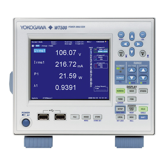
Chapter 3 Ethernet Interface (Option) Names and Functions of Parts Front Panel RESET PAGE PAGE RANGE ELEMENT VOLTAGE CURRENT ELEMENT AUTO AUTO DISPLAY NUMERIC WAVE OTHERS FORM ITEM CURSOR INTEGRATOR START/ SETUP HOLD STOP POWER INPUT INFO RESET SINGLE FILE IMAGE STORE LOCAL... -
Page 19: Ethernet Interface Functions And Specifications
• The REMOTE indicator is turned ON. • All keys except the LOCAL key are disabled. • Settings entered in local mode are retained even when the WT500 switches to remote mode. When Switching from Remote to Local Mode Pressing LOCAL key in remote mode puts the instrument in local mode. -
Page 20: App
3.2 Ethernet Interface Functions and Specifications Connecting the WT500 and the PC For the procedure of connecting the WT500 to a PC, see section 11.2 in the User’s Manual IM760201-01E. Entering TCP/IP Settings You must enter TCP/IP settings to control the WT500 from a PC using the Ethernet interface. -
Page 21: Chapter 4 Before Programming
<Program header> Space <Program data> messages. Program messages that request a response to be sent from the WT500 to the controller are called queries. Messages that the controller <Program Header> receives from the WT500 are called response The program header indicates the command type. For messages. - Page 22 4.1 Messages Response Message Unit Format • If a program message containing multiple message The response message unit format is shown below. units is sent, and the message contains incomplete units, the instrument attempts to execute the ones that are believed to be complete. However, these <Response header>...
-
Page 23: Commands
Commands Commands Example Group of commands related to There are three types of commands (program headers) integration measurement :INTEGrate? that are sent from the controller to the instrument. :INTEGrate:MODE They differ in their program header formats. :INTEGrate:TIMer :INTEGrate:RTIMe? Common Command Header :INTEGrate:RTIMe:STARt Commands that are defined in the IEEE 488.2-1992 :INTEGrate:RTIMe:END... - Page 24 4.2 Commands When Separating Commands with <PMT> Header Interpretation Rules If a terminator is used to separate two commands, The instrument interprets the header that is received each command is a separate message. Therefore, the according to the rules below. common header must be specified for each command •...
-
Page 25: Responses
Responses When the controller sends a message unit that has a question mark ( ? ) in its program header (query), the instrument returns a response message to the query. A response message is returned in one of the following two forms. -
Page 26: Data
Data Data • For the <NR3> format, the “+” sign after the “E” A data section comes after the header. A space must can be omitted. However, the “−” sign cannot be be included between the header and the data. The omitted. data contains conditions and values. Data is classified •... - Page 27 <Block Data> <Block data> is arbitrary 8-bit data. It is only used in <Character Data> response messages on the WT500. The syntax is as <Character Data> is a specified string of character data follows: (a mnemonic). It is mainly used to indicate options...
-
Page 28: Synchronization With The Controller
Synchronization with the Controller Overlap Commands and Sequential Commands Synchronizing with Overlap Commands There are two types of commands, overlap commands Using the *WAI Command The *WAI command holds the subsequent commands and sequential commands. In the case of overlap commands, the execution of the next command may until the overlap command is completed. - Page 29 (Wait for a service request) is the same as the previous data to be received. This :INPut:VOLTage:RANGe: is because the WT500 returns the current measured ELEMent1?<PMT> data regardless of whether the measured data has been updated since the previous query.In this case, the “...
- Page 30 4.5 Synchronization with the Controller Using the Extended Event Register Using the COMMunicate:WAIT command The “ COMMunicate:WAIT ” command halts The changes in the condition register can be reflected in the extended event register (page 6-7). communications until a specific event is generated. Example :STATus:FILTer1 FALL;:STATus: Example :STATus:FILTer1 FALL;:STATus: EESE 1;EESR?;*SRE 8<PMT>...
-
Page 31: Chapter 5 Communication Commands
Chapter 5 Communication Commands A List of Commands Command Function Page COMMunicate Group :COMMunicate? Queries all communication settings. :COMMunicate:HEADer Sets or queries whether or not a header is added to the response to a query. :COMMunicate:LOCKout Sets or clears local lockout. :COMMunicate:OPSE Sets or queries the overlap command that is used by the *OPC , *OPC? , and *WAI commands. - Page 32 5.1 A List of Commands Command Function Page :DISPlay:NUMeric:NORMal? Queries all numeric display settings. 5-14 :DISPlay:NUMeric[:NORMal]:ALL? Queries all numeric display settings (in All display mode). 5-14 :DISPlay:NUMeric[:NORMal]:ALL: Sets or queries the cursor position in the numeric display (in All display 5-14 CURSor mode).
- Page 33 5.1 A List of Commands Command Function Page :DISPlay:WAVE:SVALue Sets or queries the on/off status of the scale value display. 5-19 :DISPlay:WAVE:TDIV Sets or queries the waveform Time/div value. 5-20 :DISPlay:WAVE:TLABel Sets or queries the on/off status of the waveform labels. 5-20 :DISPlay:WAVE:TRIGger? Queries all trigger settings.
- Page 34 5.1 A List of Commands Command Function Page IMAGe Group :IMAGe? Queries all screen image data save settings. 5-29 :IMAGe:ABORt Aborts the saving of screen image data. 5-29 :IMAGe:COLor Sets or queries the color tone of the screen image data that will be 5-29 saved.
- Page 35 5.1 A List of Commands Command Function Page [:INPut]:SCALing: Collectively sets the scaling constant of all elements. 5-34 {VT|CT|SFACtor}[:ALL] [:INPut]:SCALing: Sets or queries the scaling constant of the specified element. 5-34 {VT|CT|SFACtor}:ELEMent<x> [:INPut]:SYNChronize? Queries the synchronization source of all elements. 5-34 [:INPut]:SYNChronize[:ALL] Collectively sets the synchronization source of all elements.
- Page 36 :STORe:COUNt Sets or queries the store count. 5-55 :STORe:FILE? Queries all settings related to the saving of the data stored in the WT500 5-55 to files. :STORe:FILE:ANAMing Sets or queries whether or not files that the stored data will be saved to 5-55 will be automatically named.
- Page 37 5.1 A List of Commands Command Function Page :STORe:FILE:CONVert:ABORt Stops the conversion of a numeric data file to CSV format. 5-55 :STORe:FILE:CONVert:EXECute Converts a stored numeric data file to CSV format. 5-55 :STORe:FILE:CONVert:MODE Sets or queries the conversion mode used to convert stored numeric 5-55 data files to CSV format.
- Page 38 5.1 A List of Commands Command Function Page :WAVeform:STARt Sets or queries the output start point of the waveform display data that is 5-61 transmitted by the :WAVeform:SEND? command. :WAVeform:TRACe Sets or queries the target waveform for the commands in the WAVeform 5-61 group.
- Page 39 COMMunicate Group The commands in this group deal with communication. There are no front panel keys that correspond to the commands in this group. :COMMunicate? :COMMunicate:OPSR? Function Queries all communication settings. (Operation Pending Status Register) Syntax :COMMunicate? Function Queries the operation pending status register. Example :COMMUNICATE? ->...
- Page 40 5.2 COMMunicate Group :COMMunicate:VERBose Function Sets or queries whether the response to a query is returned fully spelled out (example: “:INPUT: VOLTAGE:RANGE:ELEMENT1 1.000E+03”) or using abbreviation (example: “:VOLT:RANG: ELEM1 1.000E+03”). Syntax :COMMunicate:VERBose {<Boolean>} :COMMunicate:VERBose? Example :COMMUNICATE:VERBOSE ON :COMMUNICATE:VERBOSE? -> :COMMUNICATE:VERBOSE 1 :COMMunicate:WAIT Function Waits for a specified extended event to occur.
- Page 41 CURSor Group The commands in this group deal with cursor measurements. You can make the same settings and queries that you can make by using CURSOR (SHIFT + FORM) on the front panel. :CURSor:BAR:{Y<x>|DY}? :CURSor? Function Queries the measured value of the specified cursor Function Queries all cursor measurement settings.
- Page 42 5.3 CURSor Group :CURSor:TRENd[:STATe] :CURSor:WAVE:PATH Function Sets or queries the on/off status of the cursor Function Sets or queries the cursor path in the waveform display in the trend display. display. Syntax :CURSor:TRENd[:STATe] {<Boolean>} Syntax :CURSor:WAVE:PATH {MAX|MIN|MID} :CURSor:TRENd:STATe? :CURSor:WAVE:PATH? Example :CURSOR:TREND:STATE ON Example :CURSOR:WAVE:PATH MAX...
- Page 43 DISPlay Group The commands in this group deal with the screen display. You can make the same settings and queries that you can make by pressing INPUT INFO (SHIFT + SETUP) and the keys in the DISPLAY area. :DISPlay:BAR:ORDer :DISPlay? Function Sets or queries the bar graph starting and ending Function...
- Page 44 5.4 DISPlay Group :DISPlay:MODE :DISPlay:NUMeric[:NORMal]:ALL:CURSor Function Sets or queries the display mode. Function Sets or queries the cursor position in the numeric display (in All display mode). Syntax :DISPlay:MODE {NUMeric|WAVE|TRENd| BAR|VECTor} Syntax :DISPlay:NUMeric[:NORMal]:ALL: :DISPlay:MODE? CURSor {<Function>} NUMeric = Only displays numeric values. :DISPlay:NUMeric[:NORMal]:ALL:CURSor? WAVE = Only displays waveforms.
- Page 45 5.4 DISPlay Group :DISPlay:NUMeric[:NORMal]:FORMat :DISPlay:NUMeric[:NORMal]:LIST:HEADer Function Sets or queries the numeric display format. Function Sets or queries the cursor position of the header section in the numeric display (in the list display Syntax :DISPlay:NUMeric[:NORMal]: modes). FORMat {VAL4|VAL8|VAL16|MATRix|ALL| SINGle|DUAL} Syntax :DISPlay:NUMeric[:NORMal]:LIST: :DISPlay:NUMeric[:NORMal]:FORMat? HEADer {<NRf>} Example...
- Page 46 5.4 DISPlay Group :DISPlay:NUMeric[:NORMal]:LIST:ORDer :DISPlay:NUMeric[:NORMal]:{VAL4|VAL8| Function Sets or queries the harmonic order cursor position VAL16|MATRix}:ITEM<x> of the data section in the numeric display (in the list Function Sets or queries the function, element, and harmonic display modes). order of the specified numeric display item (for the Syntax :DISPlay:NUMeric[:NORMal]:LIST: 4-value, 8-value, 16-value, or matrix display).
- Page 47 FUNCTION URMS,1 (order) will be the same as the order when the :DISPLAY:TREND:ITEM1:FUNCTION UK,1,1 WT500 is reset using the ITEM setting menu that :DISPLAY:TREND:ITEM1:FUNCTION? is displayed on the WT500 screen (Reset Items -> :DISPLAY:TREND:ITEM1: Exec).
- Page 48 5.4 DISPlay Group :DISPlay:TRENd:ITEM<x>:SCALing:MODE :DISPlay:VECTor? Function Sets or queries the scaling mode of the specified Function Queries all vector display settings. trend. Syntax :DISPlay:VECTor? Syntax :DISPlay:TRENd:ITEM<x>:SCALing: Example :DISPLAY:VECTOR? -> :DISPLAY: MODE {AUTO|MANual} VECTOR:··· Description This command is only valid on models with the :DISPlay:TRENd:ITEM<x>:SCALing:MODE? <x>...
- Page 49 5.4 DISPlay Group :DISPlay:WAVE:ALL :DISPlay:WAVE:MAPPing:{U<x>|I<x>} Function Collectively turns all waveform displays on or off. Function Sets or queries the split screen voltage or current waveform mapping mode. Syntax :DISPlay:WAVE:ALL {<Boolean>} Example :DISPLAY:WAVE:ALL ON Syntax :DISPlay:WAVE:MAPPing: {U<x>|I<x>} {<NRf>} :DISPlay:WAVE:FORMat :DISPlay:WAVE:MAPPing:{U<x>|I<x>}? The <x> in U<x> and I<x> = 1 to 3 (element) Function Sets or queries the display format of all waveforms.
- Page 50 5.4 DISPlay Group :DISPlay:WAVE:TDIV :DISPlay:WAVE:TRIGger:SLOPe Function Sets or queries the waveform Time/div value. Function Sets or queries the trigger slope. Syntax :DISPlay:WAVE:TDIV {<Time>} Syntax :DISPlay:WAVE:TRIGger: :DISPlay:WAVE:TDIV? SLOPe {RISE|FALL|BOTH} <Time> = 1, 2, 5, 10, 20, 50, 100, 200, or 500 (ms) :DISPlay:WAVE:TRIGger:SLOPe? Example :DISPLAY:WAVE:TDIV 5MS...
- Page 51 5.4 DISPlay Group :DISPlay:WAVE:VZoom:{U<x>|I<x>} Function Sets or queries the vertical zoom factor (level of the center position) of the specified voltage or current waveform. Syntax :DISPlay:WAVE:VZoom: {U<x>|I<x>} {<NRf>} :DISPlay:WAVE:VZoom:{U<x>|I<x>}? <x> = 1 to 3 (element) <NRf> = 0.1 to 100 Example :DISPLAY:WAVE:VZOOM:U1 1 :DISPLAY:WAVE:VZOOM:U1? ->...
- Page 52 5.4 DISPlay Group *Function Option List (Settings That Can Be Used for <Function>) (1) Numeric data functions Applicable commands :DISPlay:NUMeric[:NORMal]:{VAL4|VAL8|VAL16|MATRix}: ITEM<x> {NONE|<Function>,<Element>[,<Order>]} :DISPlay:NUMeric[:NORMal]:ALL:CURSor {<Function>} :DISPlay:TRENd:ITEM<x>[:FUNCtion] {<Function>,<Element>[,<Order >]} :NUMeric[:NORMal]:ITEM<x> {NONE|<Function>,<Element>[,<Order>]} :FILE:SAVE:NUMeric:NORMal:<Function> {<Boolean>} :STORe:NUMeric[:NORMal]:<Function> {<Boolean>} <Function> Function Name Used on the Menu <Element>...
- Page 53 5.4 DISPlay Group Functions that require the optional harmonic measurement feature. U(k) Required Required I(k) Required Required P(k) Required Required S(k) Required Required Q(k) Required Required LAMBDAK λ(k) Required Required PHIK φ(k) Required Required PHIUk φU(k) Required Required PHIIk φI(k) Required Required UHDFk...
-
Page 54: File Group
FILE Group The commands in this group deal with file operations. You can make the same settings and queries that you can make by using FILE on the front panel. :FILE? :FILE:DELete:WAVE:ASCii Function Queries all file operation settings. Function Deletes a waveform display data file. Syntax :FILE? Syntax... - Page 55 :FILE:SAVE:NAME? <String> = File name Function Presets the output on/off pattern of the element functions that are used when saving numeric data Example :FILE:SAVE:NAME "WT500" to a file. :FILE:SAVE:NAME? -> :FILE:SAVE: NAME "WT500" Syntax :FILE:SAVE:NUMeric:NORMal:PRESet<x> <x> = 1 to 2 (preset pattern number)
- Page 56 5.5 FILE Group :FILE:SAVE:NUMeric:NORMal:<Function> Function Sets or queries the on/off status of function output when saving numeric data to a file. Syntax :FILE:SAVE:NUMeric:NORMal: <Function> {<Boolean>} :FILE:SAVE:NUMeric:NORMal:<Function>? <Function> = {URMS|IRMS|P|S|Q|...} Example :FILE:SAVE:NUMERIC:NORMAL:URMS ON :FILE:SAVE:NUMERIC:NORMAL:URMS? -> :FILE:SAVE:NUMERIC:NORMAL:URMS 1 Description For information about the options available for <Function>, Function Option List 1 in the DISPlay Group section on page 5-22.
-
Page 57: Harmonics Group
HARMonics Group The commands in this group deal with harmonic measurement. You can make the same settings and queries that you can make by accessing Harmonics in the Setup Menu that appears when you press SETUP on the front panel. The commands in this group are only valid on models with the optional harmonic measurement feature. -
Page 58: Hold Group
HOLD Group The command in this group deals with the output data hold feature. You can make the same settings and queries that you can make by using HOLD on the front panel. :HOLD Function Sets or queries the on/off status of the output hold feature for display, communication, and other types of data. -
Page 59: Image Group
IMAGe Group The commands in this group deal with saving screen image data. You can make the same settings and queries that you can make by using IMAGE, MENU (SHIFT+IMAGE) on the front panel. :IMAGe? :IMAGe:FORMat Function Queries all screen image data save settings. Function Sets or queries the format of the screen image data that will be saved. - Page 60 5.8 IMAGe Group :IMAGe:SAVE:NAME Function Sets or queries the name of the screen image data file that will be saved. Syntax :IMAGe:SAVE:NAME {<String>} :IMAGe:SAVE:NAME? <String> = File name Example :IMAGE:SAVE:NAME “IMAGE1” :IMAGE:SAVE:NAME? -> :IMAGE:SAVE: NAME "IMAGE1" Description • Set the save destination drive with the :IMAGe: SAVE:DRIVe command and the directory with the :IMAGe:SAVE:CDIRectory command.
-
Page 61: Input Group
INPut Group The commands in this group deal with the measurement conditions of the input elements. You can make the same settings and queries that you can make by pressing the keys on the front panel’s measurement condition setup area (the area enclosed in light blue) and by using NULL (SHIFT + MISC) or by accessing Wiring, Range, Scaling, Sync Source, and Filters in the Setup Menu that appears when you press SETUP. - Page 62 5.9 INPut Group [:INPut]:CURRent:RANGe:ELEMent<x> [:INPut]:CURRent:SRATio? Function Sets or queries the electric current range of the Function Queries the external electric current sensor scaling specified element. ratios of all elements. Syntax [:INPut]:CURRent:RANGe:ELEMent<x> Syntax [:INPut]:CURRent:SRATio? {<Current>|(EXTernal,<Voltage>)} Example :INPUT:CURRENT:SRATIO? -> :INPUT: [:INPut]:CURRent:RANGe:ELEMent<x>? VCURRENT:SRATIO:··· <x>...
- Page 63 5.9 INPut Group [:INPut]:FILTer:FREQuency[:ALL] [:INPut]:INDependent Function Collectively sets the frequency filter of all elements. Function Sets or queries the on/off status of independent input element configuration. Syntax [:INPut]:FILTer: FREQuency[:ALL] {<Boolean>} Syntax [:INPut]:INDependent {<Boolean>} Example :INPUT:FILTER:FREQUENCY:ALL OFF [:INPut]:INDependent? Example :INPUT:INDEPENDENT OFF [:INPut]:FILTer:FREQuency:ELEMent<x>...
- Page 64 5.9 INPut Group [:INPut]:SCALing:STATe? [:INPut]:SYNChronize? Function Queries the on/off status of the scaling of all Function Queries the synchronization source of all elements. elements. Syntax [:INPut]:SYNChronize? Syntax [:INPut]:SCALing:STATe? Example INPUT:SYNCHRONIZE? -> :INPUT: Example :INPUT:SCALING:STATE? -> :INPUT: SYNCHRONIZE:··· SCALING:STATE:··· [:INPut]:SYNChronize[:ALL] [:INPut]:SCALing[:STATe][:ALL] Function Collectively sets the synchronization source of all Function...
- Page 65 5.9 INPut Group [:INPut]:VOLTage:AUTO[:ALL] [:INPut]:VOLTage:RANGe:ELEMent<x> Function Collectively turns the voltage auto range of all Function Sets or queries the voltage range of the specified elements on or off. element. Syntax [:INPut]:VOLTage: Syntax [:INPut]:VOLTage:RANGe: AUTO[:ALL] {<Boolean>} ELEMent<x> {<Voltage>} Example :INPUT:VOLTAGE:AUTO:ALL ON [:INPut]:VOLTage:RANGe:ELEMent<x>? <x>...
- Page 66 5.9 INPut Group [:INPut]:WIRing Function Sets or queries the wiring system. Syntax [:INPut]:WIRing {(P1W2|P1W3|P3W3| P3W4|V3A3)[,(P1W2|P1W3|P3W3|NONE)] [,(P1W2|NONE)]} [:INPut]:WIRing? P1W2 = Single-phase, two-wire system [1P2W] P1W3 = Single-phase, three-wire system [1P3W] P3W3 = Three-phase, three-wire system [3P3W] P3W4 = Three-phase, four-wire system [3P4W] V3A3 = Three-phase, three-wire (three-voltage, three-current) system [3P3W(3V3A)] NONE = No wiring...
-
Page 67: Integrate Group
5.10 INTEGrate Group The commands in this group deal with integration. You can make the same settings and queries that you can make by accessing Integrator in the Setup Menu that appears when you press SETUP on the front panel or by pressing INTEGRATOR (START/STOP) or RESET (SHIFT + START/STOP). - Page 68 5.10 INTEGrate Group :INTEGrate:TIMer Function Sets or queries the integration timer value. Syntax :INTEGrate:TIMer {<NRf>,<NRf>,<NRf>} :INTEGrate:TIMer? {<NRf>, <NRf>, <NRf>} = 0, 0, 0 to 10000, 0, 0 The first <NRf> = 0 to 10000 (hour) The second <NRf> = 0 to 59 (minute) The third <NRf>...
-
Page 69: Measure Group
5.11 MEASure Group The commands in this group deal with computation. You can make the same settings and queries that you can make by accessing Wiring(Efficiency), Averaging, Measure, User Function, Freq Items, and Delta Measure in the Setup Menu that appears when you press SETUP on the front panel. - Page 70 5.11 MEASure Group :MEASure:DMeasure[:SIGMA] :MEASure:EFFiciency:UDEF<x> Function Sets or queries the delta computation mode for Function Sets or queries the user-defined parameters used wiring unit Σ. in the efficiency equation. Syntax :MEASure:DMeasure[:SIGMA] {OFF| Syntax :MEASure:EFFiciency:UDEF<x> {(NONE| DIFFerence|P3W3_V3A3|ST_DT|DT_ST} P<x>|PA)[,(NONE|P<x>|PA)][,(NONE|P<x>| :MEASure:DMeasure:SIGMA? PA)][,(NONE|P<x>|PA)]} Example :MEASURE:DMEASURE:SIGMA OFF :MEASure:EFFiciency:UDEF<x>? The <x>...
- Page 71 5.11 MEASure Group :MEASure:FUNCtion<x>:EXPRession :MEASure:MHOLd Function Sets or queries the equation of the specified user- Function Sets or queries the on/off status of the MAX HOLD defined function. feature used in user-defined functions. Syntax :MEASure:FUNCtion<x>: Syntax :MEASure:MHOLd {<Boolean>} EXPRession {<String>} :MEASure:MHOLd? :MEASure:FUNCtion<x>:EXPRession? Example...
- Page 72 5.11 MEASure Group :MEASure:SQFormula Function Sets or queries the equation used to compute S (apparent power) and Q (reactive power). Syntax :MEASure:SQFormula {TYPE1|TYPE2|TYPE3} :MEASure:SQFormula? Example :MEASURE:SQFORMULA TYPE1 :MEASURE:SQFORMULA? -> :MEASURE: SQFORMULA TYPE1 Description • For information about the equations that correspond to TYPE1, 2, and 3, see the User’s Manual IM760201-01E.
-
Page 73: Numeric Group
5.12 NUMeric Group The command in this group deal with numeric data output. There are no front panel keys that correspond to the commands in this group. The NUMERIC key on the front panel is used to make the same settings and queries as the commands in the DISPlay group. :NUMeric? :NUMeric:HOLD Function... - Page 74 5.12 NUMeric Group :NUMeric:LIST? :NUMeric:LIST:ITEM<x> Function Queries all harmonic measurement numeric list Function Sets or queries the function and element of the output settings. specified harmonic measurement numeric list item. Syntax :NUMeric:LIST? Syntax :NUMeric:LIST:ITEM<x> {NONE| Example :NUMERIC:LIST? -> :NUMERIC:LIST:··· <Function>,<Element>} Description •...
- Page 75 5.12 NUMeric Group :NUMeric:LIST:PRESet :NUMeric:LIST:VALue? Function Presets the harmonic measurement numeric list Function Queries the harmonic measurement numeric list output item pattern. data. Syntax :NUMeric:LIST:PRESet {<NRf>} Syntax :NUMeric:LIST:VALue? {<NRf>} <NRf> = 1 to 4 <NRf> = 1 to 64 (item number) Example •...
- Page 76 5.12 NUMeric Group :NUMeric:NORMal? :NUMeric[:NORMal]:ITEM<x> Function Queries all numeric data output settings. Function Sets or queries the function, element, and harmonic order of the specified numeric data output item. Syntax :NUMeric:NORMal? Example :NUMERIC:NORMAL? -> :NUMERIC: Syntax :NUMeric[:NORMal]:ITEM<x> {NONE| NORMAL:··· <Function>,<Element>[,<Order>]} Description The number of numeric data items output by :NUMeric[:NORMal]:ITEM<x>? :NUMeric[:NORMal]:ITEM<x>...
- Page 77 5.12 NUMeric Group :NUMeric[:NORMal]:VALue? Function Queries the numeric data. Syntax :NUMeric[:NORMal]:VALue? {<NRf>} <NRf> = 1 to 255 (item number) Example • When <NRf> is specified: :NUMERIC:NORMAL:VALUE? 1 -> 103.79E+00 • When <NRf> is omitted: :NUMERIC:NORMAL:VALUE? -> 103.79E+00,1.0143E+00, 105.27E+00,..(omitted)..,1.428E+00 • When :NUMeric:FORMat is set to FLOat: :NUMERIC:NORMAL:VALUE? ->...
- Page 78 5.12 NUMeric Group *Numeric Data Formats (1) Normal Data • The Σ of electric power values P, S, and Q • Integrated values WH, WHP, WHM, AH, AHP, AHM, WS, and WQ • Efficiency values ETA1 and ETA2; harmonic distortion factor values UHDFk, IHDFk, and PHDFk; and distortion factor values UTHD, ITHD, and PTHD. ASCII: <NR3>...
- Page 79 The Function Option List in the DISPlay Group section contains a list of the function names used in commands (where the command syntax contains <Function>) and the function names in the WT500 display menu that correspond to them. Note This list indicates the measurement function and element that are assigned to each item number (ITEM<x>).
- Page 80 5.12 NUMeric Group Pattern 3 ITEM<x> <Function> <Element> URMS IRMS TIME NONE 16 to 29 URMS to WQ NONE 31 to 44 URMS to WQ NONE 46 to 59 URMS to WQ SIGMA NONE 61 to 255 NONE Pattern 4 ITEM<x>...
- Page 81 5.12 NUMeric Group 97 to 128 URMS to WQ SIGMA 129 to 255 NONE (2) Preset Patterns for Harmonic Measurement Numeric List Output Items These patterns apply to the :NUMeric:LIST:PRESet command. Pattern 1 ITEM<x> <Function> <Element> 4 to 6 U to P 7 to 9 U to P 10 to 64...
-
Page 82: Rate Group
5.13 RATE Group The command in this group deals with the data update rate. You can make the same settings and queries that you can make by accessing Update Rate in the Setup Menu that appears when you press SETUP on the front panel. :RATE Function Sets or queries the data update rate. -
Page 83: Status Reports
5.14 STATus Group The commands in this group are used to make settings and inquiries related to the status report. There are no front panel keys that correspond to the commands in this group. For information about the status report, see chapter 6. :STATus:ERRor? :STATus? Function... - Page 84 5.14 STATus Group :STATus:SPOLl? (Serial Poll) Function Executes serial polling. Syntax :STATus:SPOLl? Example :STATUS:SPOLL? -> :STATUS:SPOLL 0 5-54 IM 760201-17E...
-
Page 85: Store Group
• This command is an overlap command. :STORe:FILE? :STORe:FILE:CONVert:MODE Function Queries all settings related to the saving of the data stored in the WT500 to files. Function Sets or queries the conversion mode used to convert stored numeric data files to CSV format. Syntax... - Page 86 5.15 STORe Group :STORe:FILE:NAME :STORe:NUMeric[:NORMal]:{ELEMent<x>|S Function Sets or queries the name of the file to which the IGMA} stored numeric data will be saved. Function Sets or queries the on/off status of the output Syntax :STORe:FILE:NAME {<Filename>} of each element or of wiring unit Σ when storing :STORe:FILE:NAME? numeric data. Example :STORE:FILE:NAME “STORE1”...
- Page 87 Begins the storing of numeric data. Syntax :STORe:STARt Example :STORE:START Description The storage operation is executed when :STORe: SMODe is set to MANual. When :STORe:SMODe is set to RTIMe or INTEGrate, the WT500 enters into a storage wait state. 5-57 IM 760201-17E...
-
Page 88: System Group
5.16 SYSTem Group The commands in this group deal with the system. You can make the same settings and queries that you can make by using MISC on the front panel. :SYSTem? :SYSTem:LANGuage? Function Queries all system settings. Function Queries all display language settings. Syntax :SYSTem? Syntax... - Page 89 5.16 SYSTem Group :SYSTem:SUFFix? Function Queries the suffix code. Syntax :SYSTem:SUFFix? Example :SYSTEM:SUFFIX? -> :SYSTEM: SUFFIX "-M/C1/EX3/G5/FQ/7N" Description Returns the text that appears next to Suffix in the System Overview display, which can be accessed by pressing MISC. :SYSTem:TIME Function Sets or queries the time.
-
Page 90: Waveform Group
5.17 WAVeform Group The commands in this group deal with the output of the retrieved waveform display data. There are no front panel keys that correspond to the commands in this group. :WAVeform? :WAVeform:HOLD Function Queries all waveform display data output settings. Function Sets or queries whether all waveform display data will be held (on) or released (off). - Page 91 5.17 WAVeform Group :WAVeform:SEND? Function Queries the waveform display data specified by the :WAVeform:TRACe command. Syntax :WAVeform:SEND? Example • When :WAVeform:FORMat is set to ASCii: :WAVEFORM:SEND? -> <NR3>,<NR3>,... • When :WAVeform:FORMat is set to FLOat: :WAVEFORM:SEND? -> #N (N-digit byte number;...
-
Page 92: Common Command Group
Function Queries the instrument model. *ESE Syntax *IDN? (standard Event Status Enable Example *IDN? -> YOKOGAWA,760203,123456789, F1.01 register) Description The information is returned in this form: Function Sets or queries the standard event enable register. <Manufacturer>, <Model>, <Serial no.>, <Firmware Syntax *ESE {<NRf>}... - Page 93 5.18 Common Command Group *OPC? (OPeration Complete) *SRE (Service Request Enable Function Returns ASCII code 1 when the specified overlap register) command is completed. Function Sets or queries the service request enable register Syntax *OPC? value. Example *OPC? -> 1 Syntax *SRE {<NRf>} Description •...
- Page 94 • The command returns 0 if the self-test is successful and 1 if it is not. If the condition of the WT500 prevents the self-test from being executed (this happens for example if the WT500 is integrating or storing), the command will return an appropriate error code.
-
Page 95: Chapter 6 Status Reports
Chapter 6 Status Reports Status Reports Status Reports The figure below shows the status report that is read by serial polling. This status report is an extended version of the status report defined in IEEE 488.2-1992. Service request enable register &... - Page 96 6.1 Status Reports Overview of the Registers and Queues Name (Function) Writing Reading Status byte – Serial polling (RQS) *STB?(MSS) Service request enable register *SRE *SRE? (Status byte mask) Standard event register – *ESR? (Changes in device status) Standard event enable register *ESE *ESE? (Standard event register mask)
-
Page 97: Status Byte
Status Byte Status Byte 6 ESB MAV EES EAV 1 Bits 0, 1, and 7 Not used (always 0) Bit 2 EAV (Error Available) Set to 1 when the error queue is not empty. In other words, this bit is set to 1 when an error occurs. - Page 98 6.2 Status Byte Operation of the Status Byte A service request is issued when bit 6 of the status byte becomes 1. Bit 6 is set to 1 when any of the other bits becomes a 1 (when the corresponding bit of the service request enable register is also set to 1).For example, if an event occurs and any of the bits of the logical AND of the standard event register and the corresponding enable register becomes a 1, then bit 5 (ESB) is set to 1.
-
Page 99: Standard Event Register
Standard Event Register Standard Event Register CME EXE DDE QYE RQC OPC Bit 7 PON (Power ON) Set to 1 when the power is turned ON. Bit 6 URQ (User Request) Not used (always 0) Bit 5 CME (Command Error) Set to 1 when the command syntax is incorrect. - Page 100 6.3 Standard Event Register Operation of the Standard Event Register The standard event register is provided for eight different kinds of event which can occur inside the instrument. Bit 5 (ESB) of the status byte is set to 1 when any of the bits in this register becomes 1 (or when the corresponding bit of the standard event enable register becomes 1).
-
Page 101: Extended Event Register
Extended Event Register Reading the extended event register tells you whether changes in the condition register (reflecting internal conditions) have occurred. A transition filter can be applied which allows you to decide which events are reported to the extended event register. FILTer<x>... -
Page 102: Output Queue And Error Queue
Output Queue and Error Queue Output Queue The output queue is provided to store response messages to queries. For example, if you send the WAVeform:SEND? command, which requests the output of acquired data, the data is stored in the output queue until it is read. As shown below, data are stored in order and read from the oldest ones first. -
Page 103: Appendix 1 Ascii Character Codes
Appendix Appendix 1 ASCII Character Codes The following table shows the ASCII character codes. ‘ ” & ’ Index < > (RUBOUT) Address Universal Listener Talker Secondary Command Command Address Address Command Example octal GP-IB code ASCII character code hexadecimal decimal App-1 IM 760201-17E... -
Page 104: Appendix 2 Error Messages
Appendix 2 Error Messages This section explains the communication error messages. • The messages can be displayed in English or Japanese on the WT500. However, if a messages is queried with the :STATus:ERRor? command and displayed on a PC, the message is displayed in English. - Page 105 Appendix 2 Error Messages Error in Communication Execution (200 to 299) Code Messages Corrective Action Page Setting conflict Check the relevant settings. Chapter 5 Data out of range Check the range. Chapter 5 Too much data Check the length of the data. Chapter 5 Illegal parameter value Check the range.
-
Page 106: Appendix 3 Ieee 488.2-1992
Appendix 3 IEEE 488.2-1992 The GP-IB interface of the instrument conforms to the IEEE 488.2-1992 Standard. This standard specifies that the following 23 points be stated in the document. This section describes these points. (1) Of the IEEE 488.1 interface functions, the subsets that are supported See section 2.3, “GP-IB Interface Specifications.”... - Page 107 Appendix 3 IEEE 488.2-1992 (10) Communication between devices that do not follow the response syntax None. (11) Size of the response data block 1 to 308922 bytes (12) A list of supported common commands See section 5.18, “Common Command Group.” (13) Device condition after a successful calibration Measurement execution condition.
-
Page 108: Index
Index Symbols Page Page ^END ..................4-1 efficiency ................5-40 efficiency equation .............. 5-40 Numeric Enable Register ..............6-2 Page Entering TCP/IP Settings ............3-3 3P3W(3V3A)............... 5-36 error ..................5-53 4-value ................5-16 Error Messages ..............App-2 8-value ................5-16 error queue ............ - Page 109 Index Page Page line filter ................5-33 RATE Group ............... 5-52 linkage ................. 5-11 reactive power ..............5-42 Listener Capability ..............2-2 Real-time continuous integration mode ......5-37 LLO ..................2-6 Real-time normal integration mode ........5-37 Load..................5-24 Real-time store mode ............5-57 local lockout ................
- Page 110 Index Page Talker Capability ..............2-2 THD ..................5-27 The differences between SDC and DCL....... 2-7 time ..................5-59 Time/div ................5-20 total harmonic distortion ............. 5-27 transition filter .............. 5-53, 6-7 trend ................5-11, 5-17 trigger ................. 5-20 trigger level ................. 5-20 trigger mode ...............
Need help?
Do you have a question about the WT500 and is the answer not in the manual?
Questions and answers