
Subscribe to Our Youtube Channel
Related Manuals for YOKOGAWA WT3001E


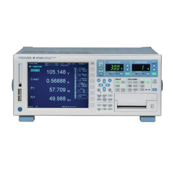
Summary of Contents for YOKOGAWA WT3001E
- Page 1 WT3001E/WT3002E/WT3003E/WT3004E Precision Power Analyzer Communication Interface IM WT3001E-17EN 3rd Edition...
- Page 2 Thank you for purchasing the WT3001E, WT3002E, WT3003E, or WT3004E Precision Power Analyzer. This Communication Interface User’s Manual describes the functions of the GP-IB, RS- 232, USB, and Ethernet interfaces and communication commands. To ensure correct use, please read this manual thoroughly before beginning operation. After reading the manual, keep it in a convenient location for quick reference whenever a question arises during operation.
- Page 3 • For purposes of this manual, the ® and TM symbols do not accompany their respective registeredtrademark names or trademark names. • Other company and product names are registeredtrademarks or trademarks of their respective holders. Revisions • 1st Edition June 2015 • 2nd Edition October 2017 • 3rd Edition August 2019 IM WT3001E-17EN...
-
Page 4: Structure Of The Manual
Describes the syntax used to transmit commands. Chapter 6 Communication Commands Describes all the commands one by one. Chapter 7 Status Reports Describes the status byte, various registers, queues, and other information. Appendix Describes reference material such as an ASCII character code table. Index IM WT3001E-17EN... -
Page 5: Conventions Used In This Manual
These symbols are referred to as BNF (Backus-Naur Form) symbols. For details on the data, see section 5.4. Symbol Meaning Example Example of Input <> ELEMent<x> <x> = 1 to 4 ->ELEMENT2 Defined value. MODE:{RMS|MEAN|DC|RMEAN}? ->MODE:RMS? Select from values given in { } . Exclusive OR NUMeric[:NORMal]:VALue? ->NUMERIC:VALUE? Can be omitted. IM WT3001E-17EN... -
Page 6: Table Of Contents
AOUTput Group ......................6-19 CBCycle Group ......................6-21 COMMunicate Group ..................... 6-24 CURSor Group ....................... 6-26 DISPlay Group ....................... 6-29 FILE Group ........................6-47 FLICker Group ........................ 6-52 6.10 HARMonics Group ......................6-57 6.11 HCOPy Group ........................ 6-59 IM WT3001E-17EN... - Page 7 Standard Event Register ....................7-5 Extended Event Register ....................7-7 Output Queue and Error Queue ..................7-9 Appendix Appendix 1 ASCII Character Codes ..................... App-1 Appendix 2 Error Messages ......................App-2 Appendix 3 IEEE 488.2-1992 ....................... App-5 Index IM WT3001E-17EN...
-
Page 8: Chapter 1 Gp-Ib Interface
IMAGE SAVE STORE MENU STORE SET PRINT MISC HELP MENU MISC key Press this key to configure communications. Rear Panel GP-IB connector Connector used to connect this instrument to the controller (PC) using a GP-IB cable. Index GP-IB (IEEE488) IM WT3001E-17EN... -
Page 9: Gp-Ib Interface Functions
• Key operations are enabled. • Settings entered in remote mode are retained even when this instrument switches to local mode. Note The GP-IB interface cannot be used simultaneously with other communication interfaces (RS- 232, USB, or Ethernet). IM WT3001E-17EN... - Page 10 Service request Full service request capability Index Remote local Full remote/local capability Parallel polling No parallel polling capability Device clear Full device clear capability Device trigger Full device trigger capability Controller No controller capability Electrical characteristics Open collector IM WT3001E-17EN...
-
Page 11: Connecting The Gp-Ib Cable
• If a converter is used along the communication cable connecting the WT and PC (for example, a GP-IB-to-USB converter), malfunctions can occur. For details, consult with your Yokogawa dealer or representative. • Multiple cables can be used to connect multiple devices. However, no more than 15 devices including the controller can be connected on a single bus. -
Page 12: Setting The Gp-Ib Control
This phrase refers to the procedures for selecting items and entering values and character strings. For details on the procedures, see section FILE IMAGE SAVE STORE 3.14 in the User’s Manual, IM WT3001E-01EN. MENU STORE SET PRINT MISC HELP MENU Press MISC to display the Misc menu. -
Page 13: Responses To Interface Messages
Interface messages are also referred to as interface commands or bus commands. They are commands that are issued by the controller. They are classified as follows: Uni-Line Messages A single control line is used to transmit uni-line messages. The following three types are available. • IFC (Interface Clear) • REN (Remote Enable) • IDY (Identify) IM WT3001E-17EN... - Page 14 In multi-line messages, SDC messages are those that require talker or listener designation and DCL messages are those that do not require the designation.yTherefore, SDC messages are directed at a particular instrument while DCL messages are directed at all instruments on the bus. IM WT3001E-17EN...
-
Page 15: Chapter 2 Rs-232 Interface (Option)
MISC key Press this key to configure communications. Rear Panel RS-232 connector EIA-574 compliant: For the 9-pin EIA-232 (RS-232) Connector used to connect this instrument to the controller (PC) using an RS-232 interface cable. Index SERIAL (RS-232) / USB IM WT3001E-17EN... -
Page 16: Interface Functions And Specifications
DELC-J9PAF-13L6 (JAE or equivalent) Hardware handshaking: Select whether to fix the CA and CB signals to TRUE or use the signals for flow control. Software handshaking: Select whether to use the X-ON and X-OFF signals to control the transmission data or both transmission and reception data. X-ON (ASCII 11H) X-OFF (ASCII 13H) Received buffer length: 256 bytes IM WT3001E-17EN... -
Page 17: Combination Of Handshaking Methods
Software handshaking is performed between this instrument and the PC. When the free area of the receive buffer decreases to 64 bytes, this instrument sends an “X-OFF” code. When the free area increases to 192 bytes, it sends an “X-ON” code. RS = True (fixed). IM WT3001E-17EN... - Page 18 Used Note The PC program must be designed so that the received buffers of both this instrument and the PC do not become full. IM WT3001E-17EN...
-
Page 19: Combination Of Data Formats
1 character Circuit idle state the next item of data (solid line). Data bit (7 or 8 bits) Stop bit Parity bit Even, odd or none Start bit 1 or 2 bits Index IM WT3001E-17EN... -
Page 20: Connection Via The Rs-232 Interface
9-Pin to 25-Pin Adapter and Signal Names The numbers inside the parentheses are pin numbers for the 25-pin connector. Signal Direction The following figure shows the direction of the signals used by the RS-232 interface of this instrument. RS [Request to send] CS [Clear to send] This Computer instrument SD [Send data] RD [Receive data] IM WT3001E-17EN... - Page 21 Request to send CB (CTS) Clear to send Signal Wiring Example The pin numbers are for the 9-pin connector. In general, use a cross cable. • OFF-OFF / XON-XON • XON-RTS(XON-RS) • CTS-RTS(CS-RS) This instrument This instrument This instrument Index IM WT3001E-17EN...
-
Page 22: Setting The Rs-232 Control
This phrase refers to the procedures for selecting items and entering values and character strings. For details on the procedures, see section FILE IMAGE SAVE STORE 3.14 in the User’s Manual, IM WT3001E-01EN. MENU STORE SET PRINT MISC HELP... - Page 23 Select the terminator from below. On the menu of this instrument, select the terminator that is used when transmitting data from this instrument. Use “Lf” or “Cr+Lf” for the terminator for receiving data on this instrument. Cr, Lf, or Cr+Lf Index IM WT3001E-17EN...
-
Page 24: Chapter 3 Usb Interface (Option)
Rear Panel USB connector for connecting to a PC A connector used to connect this instrument to the controller (such as a PC) using a USB cable. For the connection procedure, see page 3-3. Index SERIAL (RS-232) / USB IM WT3001E-17EN... -
Page 25: Usb Interface Functions And Specifications
PC system supported: A controller such as a PC running Windows Vista, Windows 7, or Windows 8/8.1 that is equipped with a USB port as standard (a separate device driver is required for the connection with a PC) IM WT3001E-17EN... -
Page 26: Connection Via The Usb Interface
• Do not connect or disconnect the USB cable after the power is turned ON until this instrument boots up completely (until this instrument is ready for operation, approximately 20 to 30 s). If you do, this instrument may malfunction. Index IM WT3001E-17EN... -
Page 27: Setting The Usb Control
This phrase refers to the procedures for selecting items and entering values and character strings. For details on the procedures, see section FILE IMAGE SAVE STORE 3.14 in the User’s Manual, IM WT3001E-01EN. MENU STORE SET PRINT MISC HELP... -
Page 28: App
3.4 Setting the USB Control Explanation You can control this instrument from a PC using the USB interface. YOKOGAWA’s dedicated USB connection device driver and library software (TMCTL) must be installed on the PC in addition to entering the settings described above. -
Page 29: Names And Functions Of Parts
Rear Panel Ethernet port (100BASE-TX) Port used to connect to the controller (PC) via the network or by a one-to-one connection. For the connection procedure, see section 5.1 in the Expansion Function User's Manual IM WT3001E-51EN. Index ETHERNET 100BASE-TX IM WT3001E-17EN... -
Page 30: Ethernet Interface Functions And Specifications
• Settings entered in remote mode are retained even when this instrument switches to local mode. Note The Ethernet interface cannot be used simultaneously with other communication interfaces (GP-IB, USB, or RS-232). Ethernet Interface Specifications Electrical and mechanical specifications: Conforms to IEEE 802.3. Number of simultaneous connections: Port number: 10001/tcp For details on other specifications, see chapter 5 in the Expansion Function User’s Manual IM WT3001E-51EN. IM WT3001E-17EN... - Page 31 Ethernet interface. The user name and password for accessing this instrument can be specified in the User Account screen under the Misc menu. For details, see “Setting the Ethernet Control” in the next section. Connecting this instrument and the PC For the procedure of connecting this instrument to a PC, see section 5.1 in the Expansion Function User’s Manual IM WT3001E-51EN. Index IM WT3001E-17EN...
-
Page 32: Setting The Ethernet Control
This phrase refers to the procedures for selecting items and entering values and character strings. For details on the procedures, see section FILE IMAGE SAVE STORE 3.14 in the User’s Manual, IM WT3001E-01EN. MENU STORE SET PRINT MISC HELP... - Page 33 Press SET. A keyboard appears. Use the keyboard to enter the user name. For keyboard operations, see section 3.14, “Entering Values and Strings” in the User’s Manual IM WT3001E-01EN. Press the cursor keys to select Password. The password setting is entered twice.
- Page 34 4.3 Setting the Ethernet Control Explanation You can control this instrument from a PC using the Ethernet interface. YOKOGAWA's dedicated library software (TMCTL) must be installed on the PC in addition to entering the settings described above. Retail Software WTViewer (760122) You can use WTViewer by setting this instrument as WT3000 emulate mode.
-
Page 35: Chapter 5 Before Programming
A response message terminator. It is NL^END. IEEE488.1. (The data byte that is sent with the END message is the last data of the program message.) • NL^END NL with an END message attached. (NL is not included in the program message.) IM WT3001E-17EN... - Page 36 • If the controller tries to receive a response message when there is none, an error occurs. If the controller tries to receive a response message before the transmission of the program message is complete, an error occurs. IM WT3001E-17EN...
-
Page 37: Commands
A common header must be specified for each command command group may contain sub-groups. even when commands belonging to the same command group are being concatenated. :INTEGrate:MODE NORMal<PMT>: Example INTEGrate:ACAL ON<PMT> IM WT3001E-17EN... - Page 38 Example “ [:INPut]:SCALing[:STATe][:ALL] ON ” can be written as “ SCAL ON .” However, the last section enclosed by braces ([]) cannot be omitted in an upper-level query. Example “ SCALing? ” and “ SCALing:STATe? ” are different queries. IM WT3001E-17EN...
-
Page 39: Responses
Naturally, the full form of the header can also be used. For this, the “ COMMunicate:VERBose ” command is used. The sections enclosed by braces ( [] ) are also omitted in the abbreviated form. IM WT3001E-17EN... -
Page 40: Data
The same form is • Response messages are always expressed in the used regardless of the size of the value. <NR3> form. Response messages are returned using the default unit without the <Multiplier> or <Unit>. IM WT3001E-17EN... - Page 41 ASCII code “0AH,” which stands for quotation marks ( ' ) or double quotation marks ( " ). “NL,” can also be a code used for data. Hence, care Form Example must be taken when programming the controller. 'ABC' "IEEE488.2-1992" <String data> IM WT3001E-17EN...
-
Page 42: Synchronization With The Controller
In such case, the overlap operation can be prevented by using the methods below. in the same way as a sequential command. Therefore, “ :INPut:VOLTage:RANGe:ELE Ment1? ” is not executed until the loading of the file is completed. IM WT3001E-17EN... - Page 43 “ *OPC? ” is read. Note Most commands are sequential commands. Overlap commands are indicated as overlap commands in chapter 6. All other commands are sequential commands. IM WT3001E-17EN...
- Page 44 The “ *SRE 8 ” command is used to generate the extended event register is set to “ 1 .” a service request solely on the cause of the extended event register. The “ :NUMeric[:NORMal]:VALue? ” command is not executed until a service request is generated. 5-10 IM WT3001E-17EN...
-
Page 45: Chapter 6 Communication Commands
:CBCycle:RESet Resets Cycle by Cycle measurement. 6-22 :CBCycle:STARt Starts Cycle by Cycle measurement. 6-22 :CBCycle:STATe? Queries the Cycle by Cycle measurement status. 6-22 :CBCycle:SYNChronize? Queries all settings related to the synchronization source for Cycle by Cycle 6-22 measurement. IM WT3001E-17EN... - Page 46 Queries all settings related to the cursor measurement on the waveform 6-28 display. :CURSor:WAVE:PATH Sets the cursor path on the waveform display or queries the current setting. 6-28 :CURSor:WAVE:POSition<x> Sets the cursor position on the waveform display or queries the current 6-28 setting. IM WT3001E-17EN...
- Page 47 :DISPlay:MATH:MATH<x>:SCALing:M Sets the scaling mode of the computed waveform or queries the current 6-34 setting. :DISPlay:MATH:MATH<x>:SCALing:S Sets the scale/division value of the manual scaling of the computed 6-34 waveform or queries the current setting. IM WT3001E-17EN...
- Page 48 Sets the graticule (grid) type or queries the current setting. 6-41 :DISPlay:WAVE:INTerpolate Sets the interpolation method of the waveform or queries the current setting. 6-41 :DISPlay:WAVE:MAPPing? Queries all settings related to the waveform mapping to the split screen. 6-41 IM WT3001E-17EN...
- Page 49 Queries all settings related to the vertical zoom factor of the waveform. 6-43 :DISPlay:WAVE:VZoom:{UALL|IALL} Collectively sets the vertical zoom factor of the waveform {voltage|current} of 6-43 all elements. :DISPlay:WAVE:VZoom:{U<x>|I<x>} Sets the vertical zoom factor of the waveform {voltage|current} of the element 6-43 or queries the current setting. Index IM WT3001E-17EN...
- Page 50 Executes the saving of the waveform display data file. 6-51 :FILE:SAVE:WAVE:TRACe Sets the waveform to be saved or queries the current setting. 6-51 :FILE:SAVE:WAVE:TYPE Sets the format of the waveform display data to be saved or queries the 6-51 current setting. IM WT3001E-17EN...
- Page 51 Sets the edition of IEC 61000-4-15 or queries the current setting. 6-55 :FLICker:RESet Resets measured flicker data. 6-55 :FLICker:STARt Starts flicker measurement. 6-56 :FLICker:STATe? Queries the status of flicker measurement. 6-56 :FLICker:TMAX? Queries all settings related to Tmax. 6-56 IM WT3001E-17EN...
- Page 52 Presets the output ON/OFF pattern of the element functions when printing 6-61 ESet<x> the numeric data list on the built-in printer. :HCOPy:PRINter:LIST[:NORMal]:<F urns ON/OFF the output of the function when printing the numerical data list 6-62 unction> using the built-in printer or queries the current setting. IM WT3001E-17EN...
- Page 53 Sets the frequency filter of the element or queries the current setting. 6-69 nt<x> [:INPut]:FILTer:LINE? Queries the line filter settings of all elements. 6-69 [:INPut]:FILTer[:LINE][:ALL] Collectively sets the line filters of all elements. 6-69 [:INPut]:FILTer[:LINE]:ELEMent Sets the line filter of the element or queries the current setting. 6-69 <x> IM WT3001E-17EN...
- Page 54 Sets the integration {start|stop} time for real-time integration mode or queries 6-74 the current setting. :INTEGrate:STARt Starts integration. 6-74 :INTEGrate:STATe? Queries the integration condition. 6-74 :INTEGrate:STOP Stops integration. 6-74 :INTEGrate:TIMer<x> Sets the integration timer time or queries the current setting. 6-75 6-10 IM WT3001E-17EN...
- Page 55 Sets the sampling frequency or queries the current setting. 6-80 :MEASure:SQFormula Sets the equation used to compute S (apparent power) and Q (reactive 6-80 power) or queries the current setting. :MEASure:SYNChronize Sets the synchronized measurement mode or queries the current setting. 6-80 6-11 IM WT3001E-17EN...
- Page 56 Queries the numeric list data from Cycle by Cycle measurement. 6-85 :NUMeric:FLICker? Queries all settings related to output of numeric data from flicker 6-85 measurement. :NUMeric:FLICker:COUNt? Queries the number of the measurement within the specified observation 6-85 period at which flicker measurement stops. 6-12 IM WT3001E-17EN...
- Page 57 6-95 “:NUMeric[:NORMal]:VALue?” or queries the current setting. :NUMeric[:NORMal]:PRESet Presets the output item pattern of numeric data. 6-95 :NUMeric[:NORMal]:VALue? Queries the numeric data. 6-96 RATE Group :RATE Sets the data update interval or queries the current setting. 6-102 6-13 IM WT3001E-17EN...
- Page 58 6-108 :STORe:WAVE:ALL Collectively turns ON/OFF the output of all waveforms when storing 6-108 waveform display data. :STORe:WAVE:{U<x>|I<x>|SPEed|TO Turns ON/OFF the output of the waveform when storing the waveform 6-108 RQue} display data or queries the current setting. 6-14 IM WT3001E-17EN...
- Page 59 Sets the output start point of the waveform display data that is transmitted by 6-113 “ :WAVeform:SEND? ” or queries the current setting. :WAVeform:TRACe Sets the target waveform for “:WAVeform:SEND?” or queries the current 6-113 setting. :WAVeform:TRIGger? Queries the trigger position of the retrieved waveform. 6-113 6-15 IM WT3001E-17EN...
- Page 60 6-116 *TRG(TRiGger) Executes single measurement (the same operation as when SINGLE is 6-116 pressed). *TST?(TeST) Performs a self-test and queries the result. 6-116 *WAI(WAIt) Holds the subsequent command until the completion of the specified overlap 6-116 operation. 6-16 IM WT3001E-17EN...
-
Page 61: Acquisition Group
(Receive the waveform sampling data of U1) :ACQuisition:TRACe I1 :ACQuisition:SEND? (Receive the waveform sampling data of I1) :ACQuisition:HOLD OFF • To retrieve new waveform sampling data, set :ACQuisition:HOLD to OFF to resume sampling, and then set :ACQuisition:HOLD to ON again. 6-17 IM WT3001E-17EN... - Page 62 • This instrument outputs the waveform sampling data in the range specified by “ :ACQuisition:{STARt|END} .” However, data exceeding the waveform sampling data range, 0 to (the total number of data points – 1), is not output. 6-18 IM WT3001E-17EN...
-
Page 63: Aoutput Group
2nd <NRf> = 0 to 59 (minute) RATE6 100.0E+00,-100.0E+00; 3rd <NRf> = 0 to 59 (second) RATE7 100.0E+00,-100.0E+00; :AOUTPUT:NORMAL:IRTIME 1,0,0 Example RATE8 100.0E+00,-100.0E+00; :AOUTPUT:NORMAL:IRTIME? -> RATE9 100.0E+00,-100.0E+00; :AOUTPUT:NORMAL:IRTIME 1,0,0 RATE10 100.0E+00,-100.0E+00; RATE11 100.0E+00,-100.0E+00; RATE12 100.0E+00,-100.0E+00; RATE13 100.0E+00,-100.0E+00; RATE14 100.0E+00,-100.0E+00; RATE15 100.0E+00,-100.0E+00; 6-19 IM WT3001E-17EN... - Page 64 Example :AOUTPUT:NORMAL:RATE1? -> :AOUTPUT:NORMAL: RATE1 100.0E+00,-100.0E+00 Description • Set the maximum value and then the minimum value. • This setting is valid when the method of setting the rated value ( :AOUTput[:NORMal]:MODE<x> ) is set to FIXed. 6-20 IM WT3001E-17EN...
-
Page 65: Cbcycle Group
• You can make the same setting or query :CBCYCLE:DISPLAY:CURSOR 1 with the “ :DISPlay:CBCycle:CURSor ” Description • Specifies the cursor position by the cycle command. number. • You can make the same setting or query with the “ :DISPlay:CBCycle:CURSor ” command. 6-21 IM WT3001E-17EN... - Page 66 Example :CBCycle:SYNChronize:SLOPe :CBCYCLE:FILTER:LINE:ELEMENT1? -> :CBCYCLE:FILTER:LINE: Function Sets the slope of the synchronization source ELEMENT1 50.0E+03 of Cycle by Cycle measurement or queries the current setting. :CBCycle:SYNChronize:SLOPe {RISE| Syntax FALL} :CBCycle:SYNChronize:SLOPe? :CBCYCLE:SYNCHRONIZE:SLOPE RISE Example :CBCYCLE:SYNCHRONIZE:SLOPE? -> :CBCYCLE:SYNCHRONIZE:SLOPE RISE 6-22 IM WT3001E-17EN...
- Page 67 :CBCycle:TRIGger:MODE Function Sets the trigger mode or queries the current setting. :CBCycle:TRIGger:MODE {AUTO|NORMal} Syntax :CBCycle:TRIGger:MODE? :CBCYCLE:TRIGGER:MODE AUTO Example :CBCYCLE:TRIGGER:MODE? -> :CBCYCLE:TRIGGER:MODE AUTO Description This is the same setting or query as with the “ :DISPlay:WAVE:TRIGger:MODE ” command. 6-23 IM WT3001E-17EN...
-
Page 68: Communicate Group
However, bits 232, USB, or Ethernet interface. An interface fixed to 0 are not set to 1. Thus, the response to message is available for the GP-IB interface. the query indicates 1 for bits 5 and 6 only. 6-24 IM WT3001E-17EN... - Page 69 7-7.) :COMMUNICATE:WAIT? 65535 -> 1 Example Operation pending status register/Overlap enable register 0 ACS When bit 5 (PRN) = 1: Built-in printer operation not complete When bit 6 (ACS) = 1: Access to the medium not complete. 6-25 IM WT3001E-17EN...
-
Page 70: Cursor Group
Description This command is valid only on models with the :CURSor:BAR[:STATe] {<Boolean>} Syntax advanced computation function (/G6 option). :CURSor:BAR:STATe? :CURSOR:BAR:STATE ON Example :CURSOR:BAR:STATE? -> :CURSOR:BAR:STATE 1 Description This command is valid only on models with the advanced computation function (/G6 option). 6-26 IM WT3001E-17EN... - Page 71 Description If the cursor display is not turned ON on the :CURSor:TRENd? Syntax trend, the following results. :CURSOR:TREND? -> :CURSOR:TREND: Example For X<x>: “****/**/** **:**:**” is returned. STATE 1;TRACE1 1;TRACE2 2; For Y<x> and DY: “NAN (Not A Number)” is POSITION1 100;POSITION2 900 returned. 6-27 IM WT3001E-17EN...
- Page 72 Description If the cursor display is not turned ON in the waveform display or queries the current setting. waveform display, “NAN (Not A Number)” is :CURSor:WAVE[:STATe] {<Boolean>} Syntax returned. :CURSor:WAVE:STATe? :CURSOR:WAVE:STATE ON Example :CURSOR:WAVE:STATE? -> :CURSOR:WAVE:STATE 1 6-28 IM WT3001E-17EN...
- Page 73 Function Queries all settings related to the bar graph. :DISPlay:BAR? Syntax :DISPLAY:BAR? -> :DISPLAY:BAR: Example FORMAT SINGLE;ITEM1 U,1;ITEM2 I,1; ITEM3 P,1;ORDER 1,100 Description This command is valid only on models with the advanced computation function (/G6 option). 6-29 IM WT3001E-17EN...
- Page 74 :DISPLAY:FFT? -> :DISPLAY:FFT: Example FORMAT SINGLE;POINT 20000; WINDOW RECTANGLE;SCOPE 0,10000; VSCALE LOG;SPECTRUM LINE;FFT1: STATE 1;OBJECT U1;LABEL “FFT1”;: DISPLAY:FFT:FFT2:STATE 1;OBJECT I1; LABEL “FFT2” Description This command is valid only on models with the advanced computation function (/G6 option). 6-30 IM WT3001E-17EN...
- Page 75 Description • This command is valid only on models with the advanced computation function (/G6 option). • Set the start point and then the end point. • Set the end point so that it is greater than or equal to (start point + 10). 6-31 IM WT3001E-17EN...
- Page 76 :DISPlay:FLICker:ELEMent {<NRf>} [:STATe] {<Boolean>} Syntax :DISPlay:FLICker:ELEMent? :DISPlay:INFOrmation:STATe? :DISPLAY:INFORMATION:STATE ON <NRf> = 1 to 4 (element) Example :DISPLAY:FLICKER:ELEMENT 1 :DISPLAY:INFORMATION:STATE? -> Example :DISPLAY:FLICKER:ELEMENT? -> :DISPLAY:INFORMATION:STATE 1 :DISPLAY:FLICKER:ELEMENT 1 Description Only available with the flicker measurement function (/FL option). 6-32 IM WT3001E-17EN...
- Page 77 :DISPlay:MATH:MATH<x>? Syntax <x> = 1, 2 (MATH) :DISPLAY:MATH:MATH1? -> :DISPLAY: Example MATH:MATH1:EXPRESSION “U1*I1”; SCALING:MODE AUTO; CENTER 0.0000E+00;SDIV 25.000E+00;: DISPLAY:MATH:MATH1:UNIT “W”: LABEL “Math1” Description This command is valid only on models with the advanced computation function (/G6 option). 6-33 IM WT3001E-17EN...
- Page 78 :DISPLAY:MATH:MATH1:UNIT? -> -> :DISPLAY:MATH:MATH1:SCALING: :DISPLAY:MATH:MATH1:UNIT “W” MODE AUTO Description This command is valid only on models with the Description This command is valid only on models with the advanced computation function (/G6 option). advanced computation function (/G6 option). 6-34 IM WT3001E-17EN...
- Page 79 CURSOR U with the advanced computation function (/G6 :DISPLAY:NUMERIC:NORMAL:ALL:CURSOR? option). • {FLICker} can only be selected with the -> :DISPLAY:NUMERIC:NORMAL:ALL: CURSOR U flicker measurement function (/FL option). Description Specify the cursor position in terms of the function name. 6-35 IM WT3001E-17EN...
- Page 80 HEADER 1;ORDER 1 -> :DISPLAY:NUMERIC:NORMAL:ALL: Description This command is valid only on models with the PAGE 1 advanced computation function (/G6 option). Description When the page number is set, the cursor position moves to the beginning of the page. 6-36 IM WT3001E-17EN...
- Page 81 • This command is valid when the cursor position ( :DISPlay:NUMeric[:NORMal]:LIST: • This command is valid when the cursor position ( :DISPlay:NUMeric[:NORMal]:LIST: CURSor ) on the numeric display (list display) is CURSor ) on the numeric display (list display) is “ORDer.” “HEADer.” 6-37 IM WT3001E-17EN...
- Page 82 <NRf> = 1 to 144 (item number, for VAL16) moves to the beginning of the page. :DISPLAY:NUMERIC:NORMAL:VAL4: Example CURSOR 1 :DISPLAY:NUMERIC:NORMAL:VAL4: CURSOR? -> :DISPLAY:NUMERIC:NORMAL: VAL4:CURSOR 1 Description Specify the cursor position in terms of the item number. 6-38 IM WT3001E-17EN...
- Page 83 Example TREND:ITEM1:FUNCTION U,1,TOTAL; is executed. For details on the order of displayed SCALING:MODE AUTO; items when reset is executed, see the User’s VALUE 100.0E+00,-100.0E+00 Manual IM WT3001E-01EN. :DISPlay:TRENd? :DISPlay:TRENd:ITEM<x>[:FUNCtion] Function Queries all settings related to the trend. Function Sets the trend item (function, element, and...
- Page 84 2nd <NRf> = 1, 3, 6, 10, 30 (minute) model. 3rd <NRf> = 3, 6, 10, or 30 (second) :DISPLAY:TREND:TDIV 0,0,3 Example :DISPLAY:TREND:TDIV? -> :DISPLAY:TREND:TDIV 0,0,3 Description Set the three <NRf>’s so that one <NRf> is a non-zero value and the other two are zeroes. 6-40 IM WT3001E-17EN...
- Page 85 :DISPLAY:WAVE:ALL ON :DISPlay:WAVE:MAPPing:MODE? Example :DISPLAY:WAVE:MAPPING:MODE AUTO Example :DISPlay:WAVE:FORMat :DISPLAY:WAVE:MAPPING:MODE? -> :DISPLAY:WAVE:MAPPING:MODE AUTO Function Sets the display format of the waveform or queries the current setting. :DISPlay:WAVE:FORMat {SINGle|DUAL| Syntax TRIad|QUAD} :DISPlay:WAVE:FORMat? :DISPLAY:WAVE:FORMAT SINGLE Example :DISPLAY:WAVE:FORMAT? -> :DISPLAY:WAVE:FORMAT SINGLE 6-41 IM WT3001E-17EN...
- Page 86 :DISPlay:WAVE:POSition:{U<x>|I<x>}? Description Set the value in terms of a percentage of the full <x> = 1 to 4 (element) scale value displayed on the screen. <NRf> = –130.000 to 130.000(%) :DISPLAY:WAVE:POSITION:U1 0 Example :DISPLAY:WAVE:POSITION:U1? -> :DISPLAY:WAVE:POSITION:U1 0.000 6-42 IM WT3001E-17EN...
- Page 87 <x> of MATH<x> = 1 to 2 (MATH) :DISPLAY:WAVE:U1 ON Example :DISPLAY:WAVE:U1? -> :DISPLAY:WAVE:U1 Description • {SPEed|TORQue} are valid only on models with the motor evaluation function (/MTR option). • MATH<x> is valid only on models with the advanced computation function (/G6 option). 6-43 IM WT3001E-17EN...
- Page 88 Not required Not required Not required Not required Not required Not required Not required Not required Not required Not required Not required Not required Not required Not required Not required Not required Not required Not required Not required 6-44 IM WT3001E-17EN...
- Page 89 Functions that require the motor evaluation function (/MTR option) SPEed Speed Not required Not required TORQue Torque Not required Not required SYNCsp SyncSp Not required Not required SLIP Slip Not required Not required Not required Not required Index 6-45 IM WT3001E-17EN...
- Page 90 Function name used in commands on the menu (Numeric display header name) LAMBda λ φ PHIU φU PHII φI In addition, the function listed below can be used for the following command. :NUMeric:LIST:ITEM<x> UHDF Uhdf IHDF Ihdf PHDF Phdf 6-46 IM WT3001E-17EN...
-
Page 91: File Group
:FILE:LOAD:SETup Description Specify the file name without the extension. Function Loads the setup parameter file. :FILE:LOAD:SETup {<Filename>} Syntax :FILE:LOAD:SETUP “SETUP1” Example Description • Specify the file name without the extension. • This command is an overlap command. 6-47 IM WT3001E-17EN... - Page 92 :FILE:SAVE:COMMENT “CASE1” Description • This command is valid only on models with the Example :FILE:SAVE:COMMENT? -> advanced computation function (/G6 option). :FILE:SAVE:COMMENT “CASE1” • Specify the file name without the extension. • This command is an overlap command. 6-48 IM WT3001E-17EN...
- Page 93 (/MTR option). :FILE:SAVE:NUMeric[:EXECute] Function Saves the numeric data to a file. :FILE:SAVE:NUMeric[:EXECute] Syntax {<Filename>} :FILE:SAVE:NUMERIC:EXECUTE “NUM1” Example Description • Specify the file name without the extension. • This command is an overlap command. 6-49 IM WT3001E-17EN...
- Page 94 ELEMENT4 0;SIGMA 0;SIGMB 0;U 1;I 1; Description For details on the output pattern when preset is P 1;S 1;Q 1;LAMBDA 1;PHI 1;FU 1; executed, see the User’s Manual IM WT3001E- FI 1;UPPEAK 0;UMPEAK 0;IPPEAK 0; 01EN. IMPEAK 0;CFU 0;CFI 0;PC 0;TIME 0;...
- Page 95 • MATH<x> is valid only on models with the advanced computation function (/G6 option). :FILE:SAVE:WAVE:TYPE Function Sets the format of the waveform display data to Index be saved or queries the current setting. :FILE:SAVE:WAVE:TYPE {BINary|ASCii| Syntax FLOat} :FILE:SAVE:WAVE:TYPE? :FILE:SAVE:WAVE:TYPE BINARY Example :FILE:SAVE:WAVE:TYPE? -> :FILE:SAVE:WAVE:TYPE BINARY 6-51 IM WT3001E-17EN...
-
Page 96: Flicker Group
Sets all settings related to the relative steady- :FLICKER:DISPLAY:ELEMENT 1 state voltage change dc or queries the current setting. Description You can make the same setting or query with the :FLICker:DC? “ :DISPlay:FLICker:ELEMent ” command. Syntax :FLICKER:DC? -> Example :FLICKER:DC:STATE 1;LIMIT 3.30 6-52 IM WT3001E-17EN... - Page 97 :FLICKER:DMAX:LIMIT 4.00 :FLICKER:DT:STATE ON Example :FLICKER:DT:STATE? -> :FLICker:DMAX[:STATe] :FLICKER:DT:STATE 1 Function Turns ON/OFF judgment of the maximum relative voltage change dmax or queries the current setting. :FLICker:DMAX[:STATe] {<Boolean>} Syntax :FLICker:DMAX:STATe? :FLICKER:DMAX:STATE ON Example :FLICKER:DMAX:STATE? -> :FLICKER:DMAX:STATE 1 6-53 IM WT3001E-17EN...
- Page 98 Sets the flicker measurement method or queries Function Initializes flicker measurement. the current setting. :FLICker:INITialize :FLICker:MEASurement {FLICker|DMAX} Syntax Syntax :FLICKER:INITIALIZE :FLICker:MEASurement? Example FLICker = Normal flicker measurement DMAX = measurement of dmax caused by manual switching :FLICKER:MEASUREMENT FLICKER Example :FLICKER:MEASUREMENT? -> :FLICKER:MEASUREMENT FLICKER 6-54 IM WT3001E-17EN...
- Page 99 :FLICKER:P4D15 ED2P0 :FLICker:PLT[:STATe] {<Boolean>} Syntax Description This is the same setting or query as with the :FLICker:PLT:STATe? “ :FLICker:EDITion ” command. :FLICKER:PLT:STATE ON Example :FLICKER:PLT:STATE? -> :FLICker:RESet :FLICKER:PLT:STATE 1 Function Resets measured flicker data. :FLICker:RESet Syntax :FLICKER:RESET Example 6-55 IM WT3001E-17EN...
- Page 100 :FLICKER:TMAX:STATE? -> :FLICKER:TMAX:STATE 1 Description This is the same setting or query as with the “ :FLICker:DT[:STATe] ” command. :FLICker:UN? Function Queries all settings related to rated voltage Un. :FLICker:UN? Syntax :FLICKER:UN? -> :FLICKER:UN: Example MODE AUTO;VALUE 230.00 6-56 IM WT3001E-17EN...
-
Page 101: Harmonics Group
(/G6 option). :HARMonics:IEC? • For details on the grouping corresponding to {OFF|TYPE1|TYPE2} , see the Expansion Function Queries all settings related to IEC harmonic measurement. Function User’s Manual IM WT3001E-51EN. :HARMonics:IEC? Syntax :HARMonics:ORDer :HARMONICS:IEC? -> :HARMONICS:IEC: Example OBJECT ELEMENT1;UGROUPING OFF;... - Page 102 • This setting is valid only in wide bandwidth harmonic measurement mode. :HARMonics:THD Function Sets the equation used to calculate the THD (total harmonic distortion) or queries the current setting. :HARMonics:THD {TOTal|FUNDamental} Syntax :HARMonics:THD? :HARMONICS:THD TOTAL Example :HARMONICS:THD? -> :HARMONICS:THD TOTAL 6-58 IM WT3001E-17EN...
- Page 103 Sets the synchronization mode of the auto print :HCOPY:AUTO:INTERVAL? -> or queries the current setting. :HCOPY:AUTO:INTERVAL 0,0,10 :HCOPy:AUTO:SYNChronize {TIMer| Syntax INTEGrate} :HCOPy:AUTO:SYNChronize? TIMer = Timer synchronized printing INTEGrate = Integration synchronized printing :HCOPY:AUTO:SYNCHRONIZE TIMER Example :HCOPY:AUTO:SYNCHRONIZE? -> :HCOPY:AUTO:SYNCHRONIZE TIMER 6-59 IM WT3001E-17EN...
- Page 104 Description This command is valid only when the built-in printer or queries the current setting. printer (/B5 option) is installed. :HCOPy:NETPrint:COLor {<Boolean>} Syntax :HCOPy:NETPrint:COLor? :HCOPY:NETPRINT:COLOR OFF Example :HCOPY:NETPRINT:COLOR? -> :HCOPY:NETPRINT:COLOR 0 Description This command is valid only on models with the Ethernet interface (/C7 option). 6-60 IM WT3001E-17EN...
- Page 105 (/B5 option) is installed. Description This command is valid only when the built-in • For details on the print pattern when preset is printer (/B5 option) is installed. executed, see the Expansion Function User’s Manual IM WT3001E-51EN. 6-61 IM WT3001E-17EN...
- Page 106 <Function>? <Function> = {U|I|P|S|Q|...} (See the function selection list (1) of “DISPlay group” on page 6-44.) :HCOPY:PRINTER:LIST:NORMAL:U ON Example :HCOPY:PRINTER:LIST:NORMAL:U? -> :HCOPY:PRINTER:LIST:NORMAL:U 1 Description This command is valid only when the built-in printer (/B5 option) is installed. 6-62 IM WT3001E-17EN...
-
Page 107: Hold Group
You can make the same settings and inquiries as when HOLD on the front panel is used. :HOLD Function Sets the output data (display, communications, etc.) hold or queries the current setting. :HOLD {<Boolean>} Syntax :HOLD? :HOLD OFF Example :HOLD? -> :HOLD 0 Index 6-63 IM WT3001E-17EN... -
Page 108: Image Group
Description Specify “..” to move up to the parent directory. current setting. :IMAGe:COMPression {<Boolean>} Syntax :IMAGe:COMPression? :IMAGE:COMPRESSION ON Example :IMAGE:COMPRESSION? -> :IMAGE:COMPRESSION 1 Description This command is valid when the format (:IMAGe:FORMat) is BMP and the color tone (:IMAGe:COLor) is {COLor|REVerse|GRAY} . 6-64 IM WT3001E-17EN... - Page 109 :IMAGE:SEND? -> #6(number of bytes, Example 6 digits)(data byte sequence) Description • The number of bytes of <Block data> is {2 + 6 + number of data points +1 (delimiter)}. • For details on <Block data>, see page 5-7. 6-65 IM WT3001E-17EN...
-
Page 110: Input Group
Collectively turns ON/OFF the current auto range ELEMENT4 1.0000;:INPUT:SCALING:CT: of all elements. ELEMENT1 1.0000;ELEMENT2 1.0000; [:INPut]:CURRent:AUTO Syntax ELEMENT3 1.0000;ELEMENT4 1.0000;: [:ALL] {<Boolean>} INPUT:SCALING:SFACTOR: :INPUT:CURRENT:AUTO:ALL ON Example ELEMENT1 1.0000;ELEMENT2 1.0000; ELEMENT3 1.0000;ELEMENT4 1.0000;: INPUT:SYNCHRONIZE:ELEMENT1 I1; ELEMENT2 I2;ELEMENT3 I3; ELEMENT4 I4;:INPUT:NULL 0 6-66 IM WT3001E-17EN... - Page 111 5 (V) (with external current sensor input) :INPUT:CURRENT:RANGE:ALL 30A Example :INPUT:CURRENT:RANGE: ALL EXTERNAL,10V Description For models that have both 2 A input elements and 30 A input elements installed, the direct current input range cannot be set collectively. Error 863 will occur. 6-67 IM WT3001E-17EN...
- Page 112 :INPUT:CURRENT:RANGE:ELEMENT1? -> • [:INPut]:CURRent:RANGe:SIGMB is valid :INPUT:CURRENT:RANGE: only on models with 4 elements. ELEMENT1 30.0E+00 • This command is invalid, if the wiring unit {ΣA|ΣB} does not exist as a result of the wiring :INPUT:CURRENT:RANGE: system setting ( [:INPut]:WIRing ). ELEMENT1 EXTERNAL,10V :INPUT:CURRENT:RANGE:ELEMENT1? -> :INPUT:CURRENT:RANGE: ELEMENT1 EXTERNAL,10.00E+00 6-68 IM WT3001E-17EN...
- Page 113 [:INPut]:INDependent? Function Collectively sets the frequency filter of all :INPUT:INDEPENDENT OFF elements. Example [:INPut]:FILTer:FREQuency :INPUT:INDEPENDENT? -> Syntax [:ALL] {<Boolean>} :INPUT:INDEPENDENT 0 :INPUT:FILTER:FREQUENCY:ALL OFF Example Description This command is valid only on models with 2 to 4 elements. 6-69 IM WT3001E-17EN...
- Page 114 Collectively turns ON/OFF the scaling of all STATE:ELEMENT1 0;ELEMENT2 0; elements. ELEMENT3 0;ELEMENT4 0;:INPUT: [:INPut]:SCALing[:STATe] Syntax SCALING:VT:ELEMENT1 1.0000; [:ALL] {<Boolean>} ELEMENT2 1.0000;ELEMENT3 1.0000; :INPUT:SCALING:STATE:ALL OFF Example ELEMENT4 1.0000;:INPUT:SCALING:CT: ELEMENT1 1.0000;ELEMENT2 1.0000; ELEMENT3 1.0000;ELEMENT4 1.0000;: INPUT:SCALING:SFACTOR: ELEMENT1 1.0000;ELEMENT2 1.0000; ELEMENT3 1.0000;ELEMENT4 1.0000 6-70 IM WT3001E-17EN...
- Page 115 • This command is invalid, if the wiring unit • [:INPut]:SYNChronize:SIGMB is valid {ΣA|ΣB} does not exist as a result of the wiring system setting ( [:INPut]:WIRing ). only on models with 4 elements. • This command is invalid, if the wiring unit {ΣA|ΣB} does not exist as a result of the wiring system setting ( [:INPut]:WIRing ). 6-71 IM WT3001E-17EN...
- Page 116 2 to 4 elements. ELEMENT1 1.000E+03; • [:INPut]:VOLTage:RANGe:SIGMB is valid ELEMENT2 1.000E+03; only on models with 4 elements. ELEMENT3 1.000E+03; • This command is invalid, if the wiring unit ELEMENT4 1.000E+03 {ΣA|ΣB} does not exist as a result of the wiring system setting ( [:INPut]:WIRing ). 6-72 IM WT3001E-17EN...
- Page 117 • Some wiring system patterns may not be selectable depending on the model type. For details on the wiring system patterns, see the User’s Manual IM WT3001E-01EN. • The pattern is fixed to P1W2 on the 1-element model. All other settings are not allowed.
-
Page 118: Integrate Group
Queries the integration start and stop times for (integration overflow, power failure) real-time integration mode. TIMeup = Integration stop due to integration timer :INTEGrate:RTIMe<x>? Syntax time :INTEGRATE:RTIME? -> Example :INTEGrate:STOP :INTEGRATE:RTIME: START 2005,1,1,0,0,0; Function Stops integration. END 2005,1,1,1,0,0 :INTEGrate:STOP Syntax :INTEGRATE:STOP Example 6-74 IM WT3001E-17EN... - Page 119 {<NRf>, <NRf>, <NRf>} = 0, 0, 0 to 10000, 0, 0 1st <NRf> = 0 to 10000 (hour) 2nd <NRf> = 0 to 59 (minute) 3rd <NRf> = 0 to 59 (second) :INTEGRATE:TIMER 1,0,0 Example :INTEGRATE:TIMER? -> :INTEGRATE:TIMER 1,0,0 Index 6-75 IM WT3001E-17EN...
-
Page 120: Measure Group
Description The averaging of measurement functions of UNIT “V”;:MEASURE:FUNCTION10: harmonic measurement (option) is valid only STATE 0;EXPRESSION “I(E1,ORT)”; when TYPE = EXPonent (attenuation constant). UNIT “A”;:MEASURE:FUNCTION11: For details, see the User’s Manual IM WT3001E- STATE 0;EXPRESSION “U(E1,ORT)”; 01EN. UNIT “V”;:MEASURE:FUNCTION12: STATE 0;EXPRESSION “I(E1,ORT)”; :MEASure:AVERaging[:STATe] UNIT “A”;:MEASURE:FUNCTION13:... - Page 121 Description The averaging of measurement functions of <x> harmonic measurement (option) is valid only for “EXPonent.” For details, see the User’s Manual Function Sets the wiring compensation of the element or IM WT3001E-01EN. queries the current setting. :MEASure:COMPensation:WIRing: Syntax :MEASure:COMPensation? ELEMent<x> {OFF|U_I|I_U}...
- Page 122 • Parameters 2 to 4 can be omitted. Omitted ETA2 PA,PB;ETA3 OFF;ETA4 OFF; parameters are set to NONE. UDEF1 P1;UDEF2 P1 • Parameters are omitted when all of the subsequent parameters are NONE for parameters 2 to 4 in the response to a query. 6-78 IM WT3001E-17EN...
- Page 123 Queries all settings related to the computation of EXPRESSION “UMN(E1)” Pc (Corrected Power). :MEASure:PC? Syntax :MEASURE:PC? -> :MEASURE:PC: Example IEC 1976;P1 0.5000;P2 0.5000 Description If the equation ( :MEASure:PC:IEC ) is set to 2011, “IEC 1993” is returned as a response. 6-79 IM WT3001E-17EN...
- Page 124 Sets the sampling frequency or queries the current setting. :MEASure:SAMPling {AUTO|CLKA|CLKB| Syntax CLKC} :MEASure:SAMPling? :MEASURE:SAMPLING AUTO Example :MEASURE:SAMPLING? -> :MEASURE:SAMPLING AUTO Description For details on the sampling frequency corresponding to {AUTO|CLKA|CLKB|CLKC} , see the User’s Manual IM WT3001E-01EN. 6-80 IM WT3001E-17EN...
- Page 125 ( :MOTor:SPEed:TYPE ) is “ANALog Function Sets the scaling factor used for motor output (analog input).” computation or queries the current setting. :MOTor:PM:SCALing {<NRf>} Syntax :MOTor:PM:SCALing? <NRf> = 0.0001 to 99999.9999 :MOTOR:PM:SCALING 1 Example :MOTOR:PM:SCALING? -> :MOTOR:PM:SCALING 1.0000 6-81 IM WT3001E-17EN...
- Page 126 :MOTor:SPEed:SCALing {<NRf>} Syntax :MOTor:TORQue? :MOTor:SPEed:SCALing? <NRf> = 0.0001 to 99999.9999 Function Queries all settings related to the torque. :MOTOR:SPEED:SCALING 1 :MOTor:TORQue? Example Syntax :MOTOR:SPEED:SCALING? -> :MOTOR:TORQUE? -> :MOTOR:TORQUE: Example :MOTOR:SPEED:SCALING 1.0000 TYPE ANALOG;RANGE 20.0E+00;AUTO 0; SCALING 1.0000;UNIT “Nm” 6-82 IM WT3001E-17EN...
- Page 127 :MOTOR:TORQUE:UNIT “Nm” Function Queries all settings related to the rated value of the torque signal (pulse input format). Description This command does not affect the computation :MOTor:TORQue:RATE? Syntax result. :MOTOR:TORQUE:RATE? -> Example :MOTOR:TORQUE:RATE: UPPER 50.0000,15.000E+03; LOWER -50.0000,5.000E+03 6-83 IM WT3001E-17EN...
- Page 128 Syntax the current setting. :NUMeric:CBCycle:END? :NUMeric:CBCycle:STARt {<NRf>} Syntax :NUMeric:CBCycle:STARt? <NRf> = 1 to 3000 (cycle number) :NUMERIC:CBCYCLE:END 100 Example <NRf> = 1 to 3000 (cycle number) :NUMERIC:CBCYCLE:END -> :NUMERIC:CBCYCLE:START 1 Example :NUMERIC:CBCYCLE:END 100 :NUMERIC:CBCYCLE:START -> :NUMERIC:CBCYCLE:START 1 6-84 IM WT3001E-17EN...
- Page 129 • For the values of “ :NUMeric:FLICker:FUNCtion:ITEM<x> ”, that are output, see “Numeric Data Format” at the end of this group (page 6-97). only the number of numeric data output items specified in “ :NUMeric:FLICker:FUNCtion:NUMber ” are output. 6-85 IM WT3001E-17EN...
- Page 130 DT function, <Function> = {TIME|UN|FU|DC|DMAX|DT| and the measured data that is output is also TMAX|PST|PLT} the same. <Element> = {<NRf>} (<NRf> = 1 to 4) <Period> = {CURRent|<NRf>|ALL} (<NRf> = 1 to 99) 6-86 IM WT3001E-17EN...
- Page 131 • For the values of “ :NUMeric:FLICker:INFOrmation: • When <NRf> is specified, only the numeric ITEM<x> ”, only the number of data for that item is output. numeric data output items specified in “ :NUMeric:FLICker:FUNCtion: INFOrmation:NUMber ” are output. 6-87 IM WT3001E-17EN...
- Page 132 Judgment results for short-term Required Required flicker value Pst JPLT Judgment results for long-term Required Not required flicker value Plt * Tmax for IEC 61000-3-3 Edition 3.0, d(t) for IEC 61000-3-3 Edition 2.0. 6-88 IM WT3001E-17EN...
- Page 133 Description • Only available with the flicker measurement function (/FL option). • If parameters are omitted from “ :NUMeric: FLICker:INFOrmation:VALue? ”, judgment results from 1 to (specified value) are output in order. • The initial setting for the number of judgment results is 7. 6-89 IM WT3001E-17EN...
- Page 134 • Returns the observation period numbers marked with an asterisk (*) in the No. column of the numeric list in the flicker measurement screen. If no asterisks are displayed (such as after a reset or during initialization), 0 is returned. 6-90 IM WT3001E-17EN...
- Page 135 For 3 element models, 22 data from TIME to PLT3 are output. For 4 element models, 29 data from TIME to PLT4 are output. • If the parameters are specified, the numeric data of the specified observation period is output. 6-91 IM WT3001E-17EN...
- Page 136 • If ON is specified when :NUMeric:HOLD is ON, the numeric data is cleared once, and the most recent numeric data is held internally. This method can be used when retrieving numeric data continuously (no need to set :NUMeric:HOLD to OFF each time). 6-92 IM WT3001E-17EN...
- Page 137 • For details on the output items that are preset, advanced computation function (/G6 option). see “(2) Preset Pattern of the Numeric List Data Output Items of Harmonic Measurement ” (see page 6-100). • By default, output items of “Pattern 2” is selected. 6-93 IM WT3001E-17EN...
- Page 138 “ :NUMeric:LIST:NUMber ” is output in order (up to 102*” :NUMeric:LIST:NUMber ” items of data). • For the format of the individual numeric data that is output, see “Numeric Data Format” at the end of this group of commands (see page 6-97). 6-94 IM WT3001E-17EN...
- Page 139 • By default, output items of “Pattern 2” is the end are set to “NONE.” selected. • If the 2nd <NRf> is omitted, only the output item of the delete start number is deleted. 6-95 IM WT3001E-17EN...
- Page 140 1 to “ :NUMeric[:NORMal]:NUMber ” is output in order. • For the format of the individual numeric data that is output, see “Numeric Data Format” at the end of this group of commands (see page 6-97). 6-96 IM WT3001E-17EN...
- Page 141 -180.000 to 180.000 with lead (D) and lag (G) set to negative and positive values, respectively. • For the Σ of power values (P, S, Q, and PC), the number of digits of the mantissa may be equal to 7 (the maximum significant digits) depending on the combination of the voltage range and current range (power range). See the list of power ranges in the User’s Manual IM WT3001E-01EN. 6-97 IM WT3001E-17EN...
- Page 142 TOTal NONE, 51 to 59 U to FI, SIGMB, TOTal NONE, 61 to 255 NONE, • Pattern 2 ITEM<x> <Function>, <Element>, <Order> TOTal TOTal TOTal TOTal TOTal LAMBda, TOTal PHI, TOTal (TOTal) (TOTal) UPPeak, (TOTal) UMPeak, (TOTal) 6-98 IM WT3001E-17EN...
- Page 143 61 to 74 U to WQ, SIGMA, TOTal NONE, 76 to 89 U to WQ, SIGMB, TOTal NONE, 91 to 255 NONE, • Pattern 4 ITEM<x> <Function>, <Element>, <Order> TOTal TOTal TOTal TOTal TOTal LAMBda, TOTal PHI, TOTal (TOTal) 6-99 IM WT3001E-17EN...
- Page 144 U to P, 13 to 64 NONE, • Pattern 2 ITEM<x> <Function>, <Element> PHIU, PHII, 6 to 10 U to PHII, 11 to 15 U to PHII, 16 to 20 U to PHII, 21 to 64 NONE, 6-100 IM WT3001E-17EN...
- Page 145 37 to 64 NONE, • Pattern 4 ITEM<x> <Function>, <Element> LAMBda, PHI, PHIU, PHII, Index 15 to 28 U to XP, 29 to 42 U to XP, 43 to 56 U to XP, 57 to 64 NONE, 6-101 IM WT3001E-17EN...
-
Page 146: Rate Group
:RATE Function Sets the data update interval or queries the current setting. :RATE {<Time>} Syntax :RATE? <Time> = 50, 100, 250, 500 (ms), 1, 2, 5, 10, or 20 (s) :RATE 500MS Example :RATE? -> :RATE 500.0E-03 6-102 IM WT3001E-17EN... - Page 147 Description For details on the extended event register, see Function Sets whether to attach message information to chapter 7, “Status Report.” the response to the “STATus:ERRor?” query (ON/ OFF) or queries the current setting. :STATus:QMESsage {<Boolean>} Syntax :STATus:QMESsage? :STATUS:QMESSAGE ON Example :STATUS:QMESSAGE? -> :STATUS:QMESSAGE 1 6-103 IM WT3001E-17EN...
- Page 148 :STATus:SPOLl? (Serial Poll) Function Executes serial polling. :STATus:SPOLl? Syntax :STATUS:SPOLL? -> :STATUS:SPOLL 0 Example Description This command is dedicated to the optional RS- 232, USB, or Ethernet interface. An interface message is available for the GP-IB interface. 6-104 IM WT3001E-17EN...
-
Page 149: Store Group
:STORe:FILE:TYPE {ASCii|FLOat} Function Queries all settings related to the saving of the Syntax :STORe:FILE:TYPE? stored data. :STORe:FILE? :STORE:FILE:TYPE ASCII Syntax Example :STORE:FILE? -> :STORE:FILE: :STORE:FILE:TYPE? -> :STORE:FILE:TYPE Example TYPE ASCII;ANAMING 1;NAME “DATA1”; ASCII COMMENT “CASE1” 6-105 IM WT3001E-17EN... - Page 150 Description The initialization takes place immediately when initializing the storage memory using the “ :STORe:MEMory:INITialize ” command regardless of the setting specified with this command. :STORe:MEMory:CONVert:ABORt Function Abort converting the stored data from the memory to the file. :STORe:MEMory:CONVert:ABORt Syntax :STORE:MEMORY:CONVERT:ABORT Example 6-106 IM WT3001E-17EN...
- Page 151 WS 0;WQ 0;ETA1 0;ETA2 0;ETA3 0; Description For details on the storage pattern when preset is ETA4 0;F1 0;F2 0;F3 0;F4 0;F5 0; executed, see the User’s Manual IM WT3001E- F6 0;F7 0;F8 0;F9 0;F10 0;F11 0; 01EN. F12 0;F13 0;F14 0;F15 0;F16 0;...
- Page 152 Sets the store mode or queries the current setting. :STORe:SMODe {MANual|RTIMe| Syntax INTEGrate} :STORe:SMODe? MANual = Manual store mode RTIMe = Real-time store mode INTEGrate = Integration synchronization store mode :STORE:SMODE MANUAL Example :STORE:SMODE? -> :STORE:SMODE MANUAL 6-108 IM WT3001E-17EN...
-
Page 153: System Group
:SYSTem:ECLear Syntax :SYSTem:CLOCk:SNTP[:EXECute] Syntax :SYSTEM:ECLEAR Example :SYSTEM:CLOCK:SNTP:EXECUTE Example Description Available only with Ethernet (/C7 option). :SYSTem:FONT Function Sets the display font or queries the current setting. :SYSTem:FONT {GOTHic|ROMan} Syntax :SYSTem:FONT? :SYSTEM:FONT GOTHIC Example :SYSTEM:FONT? -> :SYSTEM:FONT GOTHIC 6-109 IM WT3001E-17EN... - Page 154 :SYSTem:LCD:COLor:GRAPh: the current setting. Syntax :SYSTem:LCD:BRIGhtness {<NRf>} MODE {DEFault|USER} Syntax :SYSTem:LCD:BRIGhtness? :SYSTem:LCD:COLor:GRAPh:MODE? :SYSTEM:LCD:COLOR:GRAPH: <NRf> = –1 to 3 Example :SYSTEM:LCD:BRIGHTNESS 2 MODE DEFAULT Example :SYSTEM:LCD:BRIGHTNESS? -> :SYSTEM:LCD:COLOR:GRAPH:MODE? -> :SYSTEM:LCD:BRIGHTNESS 2 :SYSTEM:LCD:COLOR:GRAPH: MODE DEFAULT 6-110 IM WT3001E-17EN...
- Page 155 <x> = 1 to 3 :SYSTEM:LCD:COLOR:TEXT:MODE PRESET1 Example :SYSTEM:LCD:COLOR:TEXT:MODE? -> :SYSTEM:LCD:COLOR:TEXT:MODE PRESET1 :SYSTem:SLOCk Function Sets whether to continue the SHIFT key ON state or queries the current setting. :SYSTem:SLOCk {<Boolean>} Syntax :SYSTem:SLOCk? :SYSTEM:SLOCK OFF Example :SYSTEM:SLOCK? -> :SYSTEM:SLOCK 0 6-111 IM WT3001E-17EN...
-
Page 156: Waveform Group
Description The number of data points is fixed. “1002” is :WAVEFORM:FORMAT? -> :WAVEFORM:FORMAT always returned. FLOAT Description For the differences in the waveform display data output due to the format setting, see the description for “ :WAVeform:SEND? .” 6-112 IM WT3001E-17EN... - Page 157 Sets the output start point of the waveform display data that is transmitted by “ :WAVeform:SEND? ” or queries the current setting. :WAVeform:STARt {<NRf>} Syntax :WAVeform:STARt? <NRf> = 0 to 1001 :WAVEFORM:START 0 Example :WAVEFORM:START? -> :WAVEFORM:START 0 6-113 IM WT3001E-17EN...
- Page 158 Description • Specify the value as a sum of decimal values see “Checking the Contents of the Package” in of each bit. the user’s manual, IM WT3001E-01EN. • For example, specifying “*ESE 251” will cause • In actuality, <Serial No.> is not returned the standard enable register to be set to (always 0).
- Page 159 • The default value is “*SRE 0” (all bits disabled). • A query using *SRE? will not clear the contents of the service request enable register. • For details on the service request enable register, see page 7-3. 6-115 IM WT3001E-17EN...
- Page 160 *WAI Syntax *WAI Example Description • For the description regarding how to synchronize the program using *WAI, see page 5-8. • The “ COMMunicate:OPSE ” command is used to specify the overlap command. 6-116 IM WT3001E-17EN...
-
Page 161: Chapter 7 Status Reports
& & & & & Index & & Standard event register Extended event enable register & & & & & & & & & & & & & & & & Extended event register Transit filter Condition filter IM WT3001E-17EN... - Page 162 The *ESE command is used to set the bits in the standard event enable register to 1’s or 0’s. The *ESE? command is used to query whether the bits in the standard event enable register are 1’s or 0’s. For details regarding these commands, see chapter 6. IM WT3001E-17EN...
-
Page 163: Status Byte
0. This can be done using the *SRE command. To query whether each bit of the service request enable register is 1 or 0, use *SRE? . For details on the *SRE command, see chapter 6. IM WT3001E-17EN... - Page 164 As a result, the corresponding bits in the status byte are cleared, except bit 4 (MAV), since the output queue cannot be emptied by the *CLS command. However, the output queue is also cleared if the *CLS command is received just after a program message terminator. IM WT3001E-17EN...
-
Page 165: Standard Event Register
2 of the standard event enable register to 0. This can be done using the *ESE command. To query whether each bit of the standard event enable register is 1 or 0, use the *ESE? . For details on the *ESE command, see chapter 6. IM WT3001E-17EN... - Page 166 The standard event register is cleared in the following three cases. • When the contents of the standard event register are read using the *ESR? command. • When a *CLS Command Is Received • When the instrument is power cycled. IM WT3001E-17EN...
-
Page 167: Extended Event Register
Set to 1 when the speed or torque of the motor input is overrange. Bit 15 POV (ElementX Input Peak Over) Set to 1 when peak over (input exceeding the peak) is detected in any of the elements. IM WT3001E-17EN... - Page 168 16) of the condition register in the following manner and overwrite the extended event register. RISE The specified bit of the extended event register is set to 1 when the bit of the condition register changes from 0 to 1. FALL The specified bit of the extended event register is set to 1 when the bit of the condition register changes from 1 to 0. BOTH The specified bit of the extended event register is set to 1 when the bit of the condition register changes from 0 to 1 or 1 to 0. NEVer Always 0. IM WT3001E-17EN...
-
Page 169: Output Queue And Error Queue
The error queue is emptied in the following cases (in addition to when read-out is performed). • When a *CLS command is received • When the instrument is power cycled. To see whether the error queue is empty or not, check bit 2 (EAV) of the status byte. IM WT3001E-17EN... - Page 170 Appendix 1 ASCII Character Codes The following table shows the ASCII character codes. ‘ ” & ’ Index < > (RUBOUT) Address Universal Listener Talker Secondary Command Command Address Address Command Example octal GP-IB code ASCII character code hexadecimal decimal App-1 IM WT3001E-17EN...
-
Page 171: Appendix 2 Error Messages
:STATus:ERRor? command and displayed on a PC, the message is displayed in English. • If servicing is required, contact your nearest YOKOGAWA dealer for repairs. • Only error messages related to communications are listed here. For other error messages, see User’s Manual IM WT3001E-01EN. - Page 172 Limit the length of the program message including 5-2 <PMT> to 1024 bytes or less. 440 Query UNTERMINATED after indefinite Do not specify a query after the *IDN? or *OPT? – response command. Error in System Operation (912 to 914) Code Messages Corrective Action Page Fatal error in Communication-driver Servicing required. – App-3 IM WT3001E-17EN...
- Page 173 – of the program message. Other Errors (350, 390) Code Messages Corrective Action Page 350 Queue overflow Read the error queue. Overrun error (RS-232 only) Lower the baud rate. – Note Code 350 indicates overflow of error queue. This code is returned as a response to the “STATus:ERRor?” query; it does not appear on the screen. App-4 IM WT3001E-17EN...
- Page 174 A list of program data elements that can be used in equations and their nesting limitations No equations can be used. Syntax of the responses to queries See the example of the commands given in chapter 6. App-5 IM WT3001E-17EN...
-
Page 175: Appendix 3 Ieee 488.2-1992
See section 5.5, “Synchronization with the Controller” and chapter 6. (23) The description of the execution of each command See the functions of each command in chapter 6, User’s Manual IM WT3001E- 01EN, and Expansion Function User’s Manual IM WT3001E-51EN. - Page 176 ....... 6-103, 7-2 connector and signal names..........2-6 extended event register ......5-10, 6-103, 7-2, 7-7 continuous integration mode ..........6-74 external current sensor input ..........6-67 conventions used in this manual ..........iv crest factor ................. 6-66 Index-1 IM WT3001E-17EN...
- Page 177 ............... 5-4 paper feeding..............6-60 Page parts, names of ..............3-1 password ................4-6 JPLT .................. 6-88 pattern ..............6-98, 6-100 JPST .................. 6-88 PC card, formatting of............6-47 JTOTal ................6-88 Pc(Corrected Power) ............6-80 Index-2 IM WT3001E-17EN...
- Page 178 .................. 6-39 scale value display ............6-42 trigger ..............6-23, 6-42 scaling ................6-70 two-wattmeter compensation method........ 6-77 scaling constant ..............6-69 scaling factor ..........6-81, 6-82, 6-83 scaling of trend ..............6-39 screen display..............6-29 Index-3 IM WT3001E-17EN...
- Page 179 ............6-42 waveform mapping method ..........6-41 waveform, total number of points of ........ 6-112 wiring compensation ............6-77 wiring system ..............6-73 Page XON-RS ................2-4 XON-XON ................2-3 Page zoom factor .............. 6-41, 6-43 Index-4 IM WT3001E-17EN...
Need help?
Do you have a question about the WT3001E and is the answer not in the manual?
Questions and answers