
Related Manuals for YOKOGAWA WT310EH


Summary of Contents for YOKOGAWA WT310EH
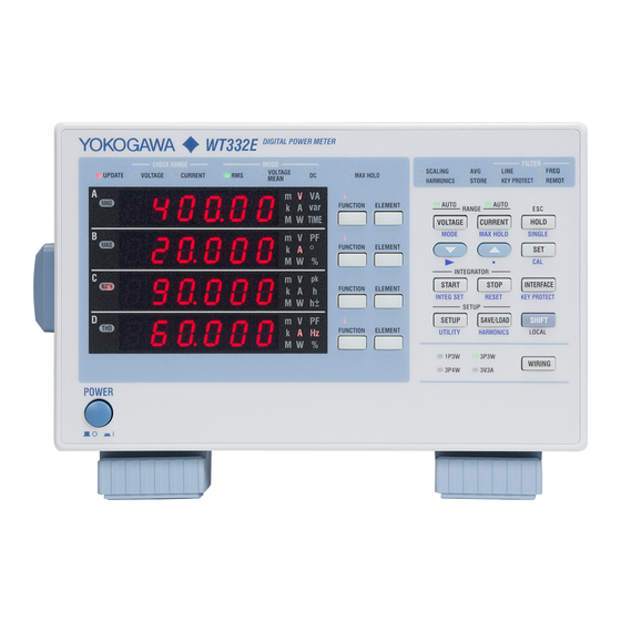
- Page 1 WT310E/WT310EH/WT332E/WT333E Digital Power Meter Communication Interface IM WT310E-17EN 2nd Edition...
- Page 2 Thank you for purchasing the WT310E, WT310EH, WT332E, or WT333E Digital Power Meter. This Communication Interface User’s Manual explains the following interface features and commands. • USB interface • GP-IB interface • RS-232 interface • Ethernet interface To ensure correct use, please read this manual thoroughly before beginning operation.
-
Page 3: About The Usb Interface And Ethernet Interface
• To use the USB communication features, your PC must have the following: • Library of this instrument (TMCTL) • USB device driver for connecting this instrument to the PC • To use the Ethernet communication features, your PC must have the following: • Library of this instrument (TMCTL) You can download the library and driver from the following web page. http://tmi.yokogawa.com/ If you install WTViewerFreePlus in your PC, the above library and driver will be installed automatically. Sample Programs You can download sample programs for this instrument from the following web page: http://tmi.yokogawa.com/ WTViewerFreePlus WTViewerFreePlus is a dedicated software application for this instrument. It is included in the... -
Page 4: Symbols And Notation Used In This Manual
Symbols and Notation Used in This Manual Notes The notes and cautions in this manual are categorized using the following symbols. WARNING Calls attention to actions or conditions that could cause serious or fatal injury to the user, and precautions that can be taken to prevent such occurrences. - Page 5 How to Use This Manual Symbols and Conventions Used in Procedural Explanations In chapters 1 to 4, the contents of the procedural explanations are indicated using the following symbols. Operations are explained using flowcharts. See the example below for an Procedure explanation of how various operations are indicated. All procedures are written under the assumption that you are starting operation at the beginning of the procedure, so you may not need to carry out all the steps in a procedure when you are changing the settings.
-
Page 6: Table Of Contents
Contents About the USB Interface and Ethernet Interface ................ii Sample Programs ..........................ii WTViewerFreePlus ........................... ii Symbols and Notation Used in This Manual ..................iii Chapter 1 USB Interface 1.1 Component Names and Functions ................... 1-1 1.2 USB Interface Features and Specifications ..............1-2 1.3 Connecting to the USB Interface ..................1-3 1.4 Configuring the USB Settings of This Instrument ............. 1-4 Chapter 2 GP-IB Interface 2.1 Component Names and Functions ................... 2-1 2.2 GP-IB Interface Features and Specifications .............. - Page 7 Contents 6.12 RATE Group ........................6-29 6.13 RECall Group ......................... 6-30 6.14 STATus group ......................... 6-31 6.15 STORe Group......................... 6-32 6.16 SYSTem Group ......................6-33 6.17 Common Command Group .................... 6-34 Chapter 7 Status Reports 7.1 About Status Reports ....................... 7-1 7.2 Status Byte ........................7-3 7.3 Standard Event Register ....................7-4 7.4 Extended Event Register ....................
-
Page 8: Chapter 1 Usb Interface
Chapter 1 USB Interface Component Names and Functions Front Panel INTERFACE key (page 1-4) Press this key to view the serial number that is used in USB TMC communication. LOCAL key Press this key to switch to local mode. In local mode, remote mode (remote control using communication commands) is cleared, and key operation becomes possible. -
Page 9: Usb Interface Features And Specifications
USB Interface Features and Specifications USB Interface Features Reception Feature • You can use the reception feature to specify the same settings that you specify by using the front panel keys. • Output requests for measured and computed data, panel setup parameters, and error codes can be received. Transmission Feature • This instrument can transmit measured and computed data. • This instrument can transmit panel setup parameters and the status byte. • This instrument can transmit error codes when errors occur. USB Interface Specifications Item Specifications Number of ports Type B connector (receptacle) Connector Electrical and mechanical Complies with USB Rev. 2.0 Supported transfer modes HS (High Speed; 480 Mbps) and FS (Full Speed; 12 Mbps) Supported protocols USBTMC-USB488 (USB Test and Measurement Class Ver. 1.0) PC running Windows 8 (32 bit/64bit), Windows 7 (32 bit/64bit), or Windows... -
Page 10: Connecting To The Usb Interface
• Do not connect or remove USB cables from the time when this instrument is turned on until operation becomes available (approximately 20 to 30 seconds). Doing so may damage this instrument. • On the WT310E and WT310EH, it is physically impossible to connect a GP-IB cable and a USB cable at the same time. Index IM WT310E-17EN... -
Page 11: Configuring The Usb Settings Of This Instrument
(Display B) Instrument number is shown in displays Close menu. C and D. Note • Only use one communication interface: USB, GP-IB, RS-232, or Ethernet. If you send commands simultaneously from more than one communication interface, this instrument will not execute the commands properly. • Install the YOKOGAWA USB TMC (Test and Measurement Class) driver on your PC. For information about how to obtain the YOKOGAWA USB TMC driver, contact your nearest YOKOGAWA dealer. You can also access the YOKOGAWA USB driver download web page and download the driver. http://tmi.yokogawa.com/ • Do not use USB TMC drivers (or software) supplied by other companies. IM WT310E-17EN... -
Page 12: Chapter 2 Gp-Ib Interface
Chapter 2 GP-IB Interface Component Names and Functions Front Panel INTERFACE key (page 2-6) Press this key to set the GP-IB address. LOCAL key Press this key to switch to local mode. In local mode, remote mode (remote control using communication commands) is cleared, and key operation becomes possible. -
Page 13: Gp-Ib Interface Features And Specifications
GP-IB Interface Features and Specifications GP-IB Interface Features Reception Feature • You can use the reception feature to specify the same settings that you specify by using the front panel keys. • Output requests for measured and computed data, panel setup parameters, and error codes can be received. Transmission Feature • This instrument can transmit measured and computed data. • This instrument can transmit panel setup parameters and the status byte. • This instrument can transmit error codes when errors occur. Note Talk-only, listen-only, and controller capabilities are not available. GP-IB Interface Specifications Item Specifications Supported devices National Instruments Corporation • PCI-GPIB or PCI-GPIB+ • PCIe-GPIB or PCIe-GPIB+ • PCMCIA-GPIB or PCMCIA-GPIB+ (not supported on Windows Vista or Windows 7.) • GPIB-USB-HS Driver NI-488.2M Version 2.8.1 and later Electrical and mechanical Conforms to IEEE St’d 488-1978... - Page 14 2.2 GP-IB Interface Features and Specifications Switching between Remote and Local Modes When Switching from Local to Remote Mode This instrument switches to remote mode when it is in local mode and it receives a REN (Remote Enable) message from the PC. • The REMOTE indicator illuminates. • All keys except the SHIFT (LOCAL) key are disabled. • Settings entered in local mode are retained even when this instrument switches to remote mode. When Switching from Remote to Local Mode When this instrument is in remote mode and you press SHIFT (LOCAL), this instrument switches to local mode. This key is disabled when local lockout (see page 2-7) has been activated by a controller.
-
Page 15: Connecting To The Gp-Ib Interface
• When connecting multiple devices, you must assign a unique address to each device. • Use cables that are 2 m or shorter in length to connect devices. • Make sure the total length of all cables does not exceed 20 m. • When devices are communicating, have at least two-thirds of the devices on the bus turned on. • To connect multiple devices, wire them in a daisy-chain or star configuration as shown below. You can also mix these configurations. Loop configuration is not allowed. • On the WT310E and WT310EH, it is physically impossible to connect a GP-IB cable and a USB cable at the same time. IM WT310E-17EN... - Page 16 2.3 Connecting to the GP-IB Interface CAUTION Be sure to turn off the PC and this instrument before you connect or remove communication cables. Otherwise, erroneous operation may result, or the internal circuitry may break. French ATTENTION Veiller à mettre le PC et l’instrument hors tension avant de brancher ou de débrancher les câbles de communication, pour éviter de provoquer des dysfonctionnements ou des courts- circuits internes. Index IM WT310E-17EN...
-
Page 17: Configuring The Gp-Ib Settings Of This Instrument
Configuring the GP-IB Settings of This Instrument This section explains the following setting for controlling this instrument remotely through a GP-IB interface: Procedure Follow the procedure indicated by the thick lines in the following menu. Setting the GP-IB Address Select the Set the address. communication function. (Display D) (Display B) Set, close menu. Press to set the number. -
Page 18: Responses To Interface Messages
Responses to Interface Messages Responses to Interface Messages Responses to Uni-Line Messages • IFC (Interface Clear) Clears the talker and listener functions. Stops data transmission if it is in progress. • REN (Remote Enable) Switches between the remote and local modes. IDY (Identify) is not supported. Responses to Multi-Line Messages (Address commands) • GTL (Go To Local) Switches the instrument to local mode. • SDC (Selected Device Clear) • Clears the program message (command) being received and the output queue (see page 7-6 for details). - Page 19 2.5 Responses to Interface Messages Multi-line Messages Eight data lines are used to transmit multi-line messages. The messages are classified as follows: • Address Commands Some address commands are valid when a device is designated as a listener, and some are valid when it is designated as a talker. The following five commands are available. Commands available to a device designated as a listener • GTL (Go To Local) • SDC (Selected Device Clear) • PPC (Parallel Poll Configure) • GET (Group Execute Trigger) Commands available to a device designated as a talker • TCT (Take Control)
-
Page 20: Chapter 3 Rs-232 Interface
Chapter 3 RS-232 Interface Component Names and Functions Front Panel INTERFACE key (page 3-5) Press this key to set the handshaking, data format, baud rate, or terminator. LOCAL key Press this key to switch to local mode. In local mode, remote mode (remote control using communication commands) is cleared, and key operation becomes possible. -
Page 21: Rs-232 Interface Features And Specifications
RS-232 Interface Features and Specifications RS-232 Interface Features Reception Feature • You can use the reception feature to specify the same settings that you specify by using the front panel keys. • Output requests for measured and computed data, panel setup parameters, and error codes can be received. Transmission Feature • This instrument can transmit measured and computed data. • This instrument can transmit panel setup parameters and the status byte. • This instrument can transmit error codes when errors occur. RS-232 Interface Specifications Item Specifications Electrical specifications Complies with EIA-574 (EIA-232 (RS-232) standard for 9-pin) Connection Point to point Transmission mode Full duplex Synchronization Start-stop synchronization... -
Page 22: Connecting To The Rs-232 Interface
Connecting to the RS-232 Interface To connect this instrument to a PC, use an interface cable that is compatible with this instrument specifications. Be sure to align the handshaking, data transfer rate, data format, and so on with the PC. For the settings, see section 3.4. Connector and Signal Names WT310E/WT310EH WT332E/WT333E DELC-J9PAF-13L6 or equivalent Pin No. Signal Name... - Page 23 AB (GND) Signal ground BA (TXD) Transmitted data BB (RXD) Received data CB (CTS) Request to send CA (RTS) Clear to send Signal Wiring Example The pin numbers are for the 9-pin connector. In general, use a crossover cable. OFF-OFF / XON-XON CTS-RTS (CS-RS) Connection Procedure Connect the cable as shown below. WT310E/WT310EH WT332E/WT333E IM WT310E-17EN...
-
Page 24: Configuring The Rs-232 Settings Of This Instrument
Configuring the RS-232 Settings of This Instrument This section explains the following setting for controlling this instrument remotely through a RS-232 interface: Procedure Follow the procedure indicated by the thick lines in the following menu. Select the communication function. Set the handshaking. Set the data format. (Display B) (Display A) (Display B) Set the baud rate. Set the terminator. - Page 25 3.4 Configuring the RS-232 Settings of This Instrument Explanation Handshaking To use the RS-232 interface to communicate with a PC, the devices on both sides must negotiate a set of rules to ensure the proper transfer of data. This negotiation is called handshaking. Because there are many handshaking methods that can be used between this instrument and the PC, you must make sure that the same method is chosen by both this instrument and the PC. You can choose any of handshaking methods shown below.
- Page 26 3.4 Configuring the RS-232 Settings of This Instrument CS-RS Data Transmission Control Hardware handshaking is performed between this instrument and the PC. If CS is set to false while this instrument is sending data, it stops the data transmission. Then, if CS is set to true, it resumes the operation. The “X-OFF” and “X-ON” signals are treated as data. Data Reception Control Hardware handshaking is performed between this instrument and the PC. When the free area of the receive buffer falls to 64 bytes, this instrument sets RS to false. When the free area reaches 192 bytes, this instrument sets RS to true. Notes on Data Reception Control When handshaking is used to control the reception of data, data may still be received from the PC even when the free space in the receive buffer drops below 64 bytes. In such cases, if the receive buffer becomes full, excessive data will be discarded, regardless of the handshaking method.
- Page 27 3.4 Configuring the RS-232 Settings of This Instrument Data Format The RS-232 interface of this instrument performs communication using start-stop synchronization. In start-stop synchronization, characters are transmitted one at a time. Each character consists of a start bit, data bits, a parity bit, and a stop bit (see the following figure). The circuit returns to the idle state (dotted line) or is activated (solid line) 1 character Circuit if the start bit of the next...
-
Page 28: Chapter 4 Ethernet Interface
Chapter 4 Ethernet Interface Component Names and Functions Front Panel UTILITY key (page 4-4) Press this key to configure TCP/IP settings. LOCAL key Press this key to switch to local mode. In local mode, remote mode (remote control using communication commands) is cleared, and key operation becomes possible. -
Page 29: Ethernet Interface Features And Specifications
Ethernet Interface Features and Specifications Ethernet Interface Features Reception Feature • You can use the reception feature to specify the same settings that you specify by using the front panel keys. • Output requests for measured and computed data, panel setup parameters, and error codes can be received. Transmission Feature • This instrument can transmit measured and computed data. • This instrument can transmit panel setup parameters and the status byte. • This instrument can transmit error codes when errors occur. Ethernet Interface Specifications Item Specifications IEEE802.3 Electrical and mechanical Simultaneous connections TCP/IP (VXI-11, Modbus/TCP) Communication protocol RJ-45 Connector type Switching between Remote and Local Modes When Switching from Local to Remote Mode... -
Page 30: Connecting To The Ethernet Interface
Connecting to the Ethernet Interface Connection Procedure Connect a UTP (Unshielded Twisted-Pair) or STP (Shielded Twisted-Pair) cable that is connected to a hub or other network device to the Ethernet port on the rear panel of this instrument. Hub or router that supports 100BASE-TX/10BASE-T WT310E/WT310EH WT332E/WT333E Network card UTP or STP cable (straight cable) -
Page 31: Configuring The Ethernet Settings Of This Instrument
Configuring the Ethernet Settings of This Instrument This section explains the following setting for remotely controlling this instrument via the Ethernet interface: Procedure Follow the procedure indicated by the thick lines in the following menu. Select Ethernet. (Display B) Select DHCP. (Display B) (Display C) Confirm the setting. - Page 32 4.4 Configuring the Ethernet Settings of This Instrument Note Only use one communication interface: USB, GP-IB, RS-232, or Ethernet. If you send commands simultaneously from more than one communication interface, this instrument will not execute the commands properly. You can view the IP address that has been assigned by the DHCP server or the IP address that you specified by following the procedure below.
-
Page 33: Chapter 5 Programming Overview App
Chapter 5 Programming Overview Messages Messages Messages are used to exchange information between <Program header> Space <Program data> the controller and this instrument. Messages that are sent from the controller to this instrument are called program messages, and messages that are sent <Program Header>... - Page 34 5.1 Messages • If the controller sends a program message Response Message Unit Syntax The response message unit syntax is as follows: containing multiple message units, but the message contains incomplete units, this instrument will try to execute the ones that are believed to be complete. <Response header> Space <Response data> However, these attempts may not always be successful.
-
Page 35: Commands
Commands Commands Example A portion of the commands from the There are three types of commands (program headers) integration command group that a controller may send to this instrument. The :INTEGrate? commands differ in their program header formats. :INTEGrate:MODE :INTEGrate:TIMer Common Command Header :INTEGrate:STARt Commands that are defined in IEEE 488.2-1992 are... - Page 36 5.2 Commands Upper-level Query An upper-level query is a query that is made by appending a question mark to a command higher in the group. The controller can receive all of the settings in a group collectively by executing a highest-level query. Some query groups which are comprised of more than three hierarchical levels can output all the lower level settings. Example :INTEGrate?<PMT> -> :INTEGRATE :MODE NORMAL;TIMER 0,0,0<RMT>...
-
Page 37: Responses
Responses Response When the controller sends a message unit that has a question mark in its program header (a query), this instrument returns a response message to the query. This instrument returns response messages in one of the following two forms. • Response Consisting of a Header and Data Responses that can be used as program messages without any changes are returned with command... -
Page 38: Data
Data Data • If a value has more significant digits than are Data contains conditions and values that are written available, the value will be rounded. after the header. A space separates the data from the header. Data is classified as follows: <Voltage>, <Current>, and <Time> Data Description <Voltage>, <Current>, and <Time> indicate decimal <Decimal> A value expressed in decimal notation values that have physical significance. -
Page 39: Index
5.4 Data • If a character string contains a double quotation <Register> <Register> indicates an integer, and can be expressed mark ( " ), the double quotation mark is expressed as in hexadecimal, octal, or binary as well as a decimal two consecutive quotation marks ( "" ). This rule also number. This is used when each bit of the value has a applies to single quotation marks. -
Page 40: Synchronization With The Controller
Synchronization with the Controller Overlap and Sequential Commands The STATus:FILTer1 FALL command sets the There are two types of commands: overlap and transition filter so that bit 0 in the extended event sequential. With overlap commands, the execution (FILTer1) is set to 1 when bit 0 in the condition of the next command may start before the execution register changes from 1 to 0, in other words when of the previous command is finished. -
Page 41: Chapter 6 Commands
Chapter 6 Commands List of Commands Command Function Page AOUTput Group Queries all D/A output settings. :AOUTput? Sets the D/A output items to their default values. :AOUTput[:NORMal]:PRESet Sets or queries a D/A output item (function or element). :AOUTput[:NORMal]:CHANnel<x> Sets or queries the rated integration time that is used in the D/A output of the :AOUTput[:NORMal]:IRTime integrated value. Sets or queries a D/A range mode. :AOUTput[:NORMal]:MODE<x> Sets or queries the maximum and minimum values for when the D/A output :AOUTput[:NORMal]:RATE<x> is in manual range mode. Sets or queries the comparison upper and lower limits for when the D/A output is in comparator mode. COMMunicate group Queries all communication settings. :COMMunicate? Sets or queries whether headers are attached to query responses. - Page 42 6.1 List of Commands Command Function Page Sets or queries the jump destination range that is used when a voltage peak 6-13 [:INPut]:VOLTage:POJump over-range occurs. Queries all electric current measurement settings. 6-13 [:INPut]:CURRent? Sets or queries the current range. 6-13 [:INPut]:CURRent:RANGe Sets or queries the current auto range on/off state. 6-13 [:INPut]:CURRent:AUTO Sets or queries the valid current range. 6-13 [:INPut]:CURRent:CONFig Sets or queries the jump destination range that is used when a current peak 6-13 [:INPut]:CURRent:POJump over-range occurs. Sets or queries the valid external current sensor range. 6-13 [:INPut]:CURRent:EXTSensor: CONFig Sets or queries the jump destination range that is used when a current peak 6-14 [:INPut]:CURRent:EXTSensor: over-range occurs. POJump Queries the external current sensor conversion ratios of all elements. 6-14 [:INPut]:CURRent:SRATio? Collectively sets the external current sensor conversion ratios of all elements. 6-14 [:INPut]:CURRent:SRATio[:ALL] Sets or queries the external current sensor conversion ratio of the specified 6-14...
- Page 43 6.1 List of Commands Command Function Page NUMeric Group Queries all numeric data output settings. 6-19 :NUMeric? Sets or queries the numeric data format. 6-19 :NUMeric:FORMat Queries all numeric data output settings. 6-19 :NUMeric:NORMal? Queries the numeric data. 6-19 :NUMeric[:NORMal]:VALue? Sets or queries the number of numeric data items that are transmitted by the 6-19 :NUMeric[:NORMal]:NUMber :NUMeric[:NORMal]:VALue? command. Sets or queries the specified numeric data output item (function, element, 6-20 :NUMeric[:NORMal]:ITEM<x> and harmonic order). 6-20 Presets the numeric data output item pattern. :NUMeric[:NORMal]:PRESet Clears numeric data output items (sets the items to NONE).
- Page 44 6.1 List of Commands Command Function Page STORe Group Queries all storage settings. 6-32 :STORe? Sets or queries the storage on/off state. 6-32 :STORe[:STATe] Sets or queries the storage interval. 6-32 :STORe:INTerval Saves setup parameters to a file. 6-32 :STORe:PANel SYSTem Group Queries all system settings. 6-33 :SYSTem? Queries the model code. 6-33 :SYSTem:MODel? Queries the suffix code. 6-33 :SYSTem:SUFFix? Queries the serial number. 6-33 :SYSTem:SERial? Queries the firmware version. 6-33 :SYSTem:VERsion[:FIRMware]? Sets or queries the on/off state of the key protection. 6-33 :SYSTem:KLOCk Sets or queries the numeric data display resolution.
-
Page 45: Aoutput Group
Chapter 6 Commands AOUTput Group The commands in this group deal with D/A output. You can make the same settings and queries that you can by pressing the UTILITY key on the front panel and then using the dA menu or by pressing the INTEG SET key and then using the dAtimE menu. The commands in this group are only valid on models with the D/A output (/DA4 or /DA12) option. :AOUTput? :AOUTput[:NORMal]:IRTime Function... - Page 46 6.2 AOUTput Group :AOUTput[:NORMal]:RATE<x> Function Sets or queries the maximum and minimum values for when the D/A output is in manual range mode. Sets or queries the comparison upper and lower limits for when the D/A output is in comparator mode. Syntax :AOUTput[:NORMal]:RATE<x> {<NRf>,<NRf>} :AOUTput[:NORMal]:RATE<x>? <x> = 1 to 12 (output channel) <Element>...
-
Page 47: Communicate Group
COMMunicate group The commands in this group deal with communications. There are no front panel keys that correspond to the commands in this group. :COMMunicate? :COMMunicate:VERBose Function Queries all communication settings. Function Sets or queries whether the response to a query Syntax :COMMunicate? is returned fully spelled out or in its abbreviated form. -
Page 48: Display Group
DISPlay group The commands in this group deal with the display. You can make the same settings and queries that you can by using keys such as the FUNCTION and ELEMENT keys on the front panel. :DISPlay? :DISPlay:HARMonics? Function Queries all display settings. Function Queries all harmonic measurement data display Syntax... - Page 49 6.4 DISPlay group Numeric Data Display Functions Applicable command :DISPlay[:NORMal]:ITEM<x> {<Function>[,<Element>]} <Function> Function WT Indicator <Element> WT Displays Voltage U Current I Active power P Apparent power S [VA] Reactive power Q [var] LAMBda Power factor λ [PF] Phase difference Φ [°] Voltage frequency fU [V Hz] Current frequency fI [A Hz] Maximum voltage: U+pk [V pk] UPPeak...
-
Page 50: Harmonics Group
HARMonics Group The commands in this group deal with harmonic measurement. You can make the same settings and queries that you can make by pressing HARMONICS on the front panel. The commands in this group are valid only on models with the harmonic measurement (/G5) option. :HARMonics? :HARMonics:DISPlay[:STATe] Function Queries all harmonic measurement settings. Function Sets or queries the on/off state of harmonic Syntax :HARMonics? measurement data display. Syntax :HARMonics:DISPlay[:STATe] {<Boolean>} :HARMonics:PLLSource Function Sets or queries the PLL source. :HARMonics:DISPlay:STATe? Syntax :HARMonics:PLLSource {U<x>|I<x>} Example :HARMONICS:DISPLAY:STATE ON :HARMonics:PLLSource? :HARMONICS:DISPLAY:STATE? <x>... -
Page 51: Hold Group
HOLD Group The command in this group deals with the output data hold feature. You can make the same settings and queries that you can make by pressing HOLD on the front panel. :HOLD Function Sets or queries the on/off state of the output hold feature for display, communication, and other types of data. -
Page 52: Input Group
[3V3A] [:INPut]:VOLTage:CONFig? Example ALL = All ranges are valid. :INPUT:WIRING P1W3 <Voltage> = See ( :INPut:VOLTage: :INPUT:WIRING? -> :INPUT:WIRING P1W3 RANGe ). Description • For the WT310E and WT310EH, the wiring Example :INPUT:VOLTAGE:CONFIG ALL system is fixed to P1W2. No other setting is :INPUT:VOLTAGE:CONFIG? allowed. -> :INPUT:VOLTAGE:CONFIG ALL • For the WT332E and WT333E, the wiring :INPUT:VOLTAGE:CONFIG 600,150,15 system cannot be set to P1W2. - Page 53 -> :INPUT:CURRENT:CONFIG • For direct current input 20.0E+00,5.0E+00,1.0E+00 • When the crest factor is set to 3 Description In the parameters, list the current ranges that you <Current> = 5, 10, 20, 50, 100, 200, 500(mA), want to enable. To enable all the ranges, specify 1, 2, 5, 10, 20(A) (WT310E) the parameter “ALL.” <Current> = 1, 2, 5, 10, 20, 40(A) (WT310EH) <Current> = 0.5, 1, 2, 5, 10, 20(A) (WT332E, [:INPut]:CURRent:POJump Function Sets or queries the jump destination range that is WT333E) • When the crest factor is set to 6 or 6A used when a current peak over-range occurs. <Current> = 2.5, 5, 10, 25, 50, 100, 250(mA), Syntax [:INPut]:CURRent:POJump 0.5, 1, 2.5, 5, 10(A) (WT310E)
- Page 54 6.7 INPut Group Description In the parameters, list the external current sensor Description The following commands are enabled only when this command is set to ON. Measurement range ranges that you want to enable. To enable all the ranges, specify the parameter “ALL.” can be skipped. :INPut:VOLTage:CONFig [:INPut]:CURRent:EXTSensor:POJump :INPut:VOLTage:POJump Function Sets or queries the jump destination range that is :INPut:CURRent:CONFig used when a current peak over-range occurs.
- Page 55 6.7 INPut Group [:INPut]:FILTer? [:INPut]:CRANge? Function Queries all input filter settings. Function Sets or queries the check range status. Syntax Syntax [:INPut]:FILTer? [:INPut]:CRANge? Example :INPUT:CRANGE? -> 0 Description • The CHECK RANGE LED status is mapped [:INPut]:FILTer:LINE Function Sets or queries the line filter. as shown below. For the response, the sum Syntax of the values of each bit is returned in decimal [:INPut]:FILTer:LINE {<Boolean>} format.
-
Page 56: Integrate Group
INTEGrate Group The commands in this group deal with integration. You can make the same settings and queries that you can make by pressing INTEG SET, START, STOP, and RESET on the front panel. :INTEGrate? :INTEGrate:STATe? Function Queries all integration settings. Function Queries the integration status. Syntax Syntax :INTEGrate? :INTEGrate:STATe? Example :INTEGRATE:STATE? -> RESET Description • The response is as follows: :INTEGrate:MODE Function Sets or queries the integration mode. RESet = Integration reset Syntax STARt = Integration in progress :INTEGrate:MODE {NORMal|CONTinuous} STOP = Integration stop :INTEGrate:MODE? -
Page 57: Math Group
MATH Group The commands in this group deal with computations. You can make the same settings and queries that you can by pressing SETUP on the front panel and using the MAtH menu. :MATH Function Sets or queries the MATH equation. Syntax :MATH {EFFiciency|CFU<x>|CFI<x>|ADD| SUB|MUL|DIV|DIVA|DIVB|AVW<x>} :MATH? <x> of {CFU|CFI} = 1 to 3 (element) <x> of {AVW} = 1 to 3 (element), 4 (Σ) Example :MATH CFU1 :MATH? ->... -
Page 58: 6.10 Measure Group
6.10 MEASure Group The commands in this group deal with computation. You can make the same settings and queries that you can by pressing SETUP on the front panel and using the AVG menu or by pressing MAX HOLD on the front panel. :MEASure? :MEASure:MHOLd Function Queries all measured and computed data output Function Sets the MAX hold on/off state. Syntax settings. :MEASure:MHOLd {<Boolean>} Syntax :MEASure? :MEASure:MHOLd? Example :MEASURE:MHOLD ON :MEASure:AVERaging? :MEASURE:MHOLD? ->... -
Page 59: Numeric Group
6.11 NUMeric Group The command in this group deal with numeric data output. There are no front panel keys that correspond to the commands in this group. The commands in the DISPlay group are used to make the same settings and queries as the FUNCTION and ELEMENT keys on the front panel. - Page 60 6.11 NUMeric Group :NUMeric[:NORMal]:ITEM<x> :NUMeric[:NORMal]:CLEar Function Sets or queries the specified numeric data output Function Clears numeric data output items (sets the items to NONE). item (function, element, and harmonic order). Syntax Syntax :NUMeric[:NORMal]:ITEM<x> {NONE| :NUMeric[:NORMal]:CLEar <Function>[,<Element>][,<Order>]} {ALL|<NRf>[,<NRf>]} ALL = Clear all items :NUMeric[:NORMal]:ITEM<x>? <x> = 1 to 255 (item number) First <NRf>...
- Page 61 6.11 NUMeric Group :NUMeric:LIST? :NUMeric:LIST:NUMber Function Queries all harmonic measurement numeric list Function Sets or queries the number of numeric data output settings. list data items that are transmitted by Syntax :NUMeric:LIST:VALue?. :NUMeric:LIST? Description • This is only valid on models with the harmonic Syntax :NUMeric:LIST:NUMber {<NRf>|ALL} measurement (/G5) option. :NUMeric:LIST:NUMber? • The number of numeric list data items output <NRf> = 1 to 32(ALL) by :NUMeric:LIST:ITEM<x> is determined by Example :NUMERIC:LIST:NUMBER 5 :NUMeric:LIST:NUMber.
- Page 62 6.11 NUMeric Group :NUMeric:LIST:ITEM<x> :NUMeric:LIST:DELete Function Sets or queries the output item (function and Function Deletes harmonic measurement numeric list data element) of the specified harmonic measurement output items. Syntax numeric list data item. :NUMeric:LIST:DELete {<NRf>[,<NRf>]} Syntax :NUMeric:LIST:ITEM<x> {NONE| 1st <NRf> = 1 to 32 (the number of the first item to delete) <Function>,<Element>} Second <NRf>...
- Page 63 6.11 NUMeric Group :NUMeric:HOLD Function Sets or queries the on/off (hold/release) status of the numeric data hold feature. Syntax :NUMeric:HOLD {<Boolean>} :NUMeric:HOLD? Example :NUMERIC:HOLD ON :NUMERIC:HOLD? -> :NUMERIC:HOLD 1 Description • If :NUMeric:HOLD is set to ON before :NUMeric[:NORMal]:VALue? or :NUMeric:LIST:VALue? is executed, all the numeric data at that point in time can be held internally. • As long as :NUMeric:HOLD is set to ON, numeric data is held even when the numeric data on the screen is updated.
- Page 64 6.11 NUMeric Group Function Option List (Settings That Can Be Used for <Function>) (1) Numeric data functions Applicable commands :NUMeric[:NORMal]:ITEM<x> {NONE|<Function>[,<Element>][,<Order>]} :AOUTput[:NORMal]:CHANnel<x> {NONE|<Function>[,<Element>]} <Function> Function WT Indicator <Element> <Order> Voltage U Current I Active power P Apparent power S [VA] Reactive power Q [var] LAMBda Power factor λ...
- Page 65 6.11 NUMeric Group <Function> Function WT Indicator <Element> <Order> [V Hz] or [A FPLL PLL source frequency fPLL Yes: Required. No: Not required. (2) Numeric List Data Output Functions (These functions require the harmonic measurement (/G5) option) Applicable command :NUMeric:LIST:ITEM<x> {NONE|<Function>,<Element>} <Function> Function Voltage U( ) Current I( ) Active power P( ) Phase difference between harmonic voltage U(k) and the fundamental wave U(1) φU( ) PHIU...
- Page 66 6.11 NUMeric Group * Preset Patterns for Numeric Data Items The Function Option List contains a list of the function names used in commands and their corresponding functions and panel LED indicators. Note This list indicates the measurement function and element that are assigned to each item number (ITEM <x>). Items that are not set to be measured are displayed or output in the same fashion as when the data does not exist.
- Page 67 6.11 NUMeric Group Pattern 3 ITEM<x> <Function> <Element> LAMBda UPPeak UMPeak IPPeak IMPeak PPPeak PMPeak 16 to 30 U to PMPeak 31 to 45 U to PMPeak 46 to 60 SIGMA U to PMPeak 61 to 255 NONE Pattern 4 ITEM<x> <Function> <Element> LAMBda UPPeak UMPeak IPPeak IMPeak TIME Index 21 to 40...
- Page 68 6.11 NUMeric Group (2) P reset Patterns for Harmonic Measurement Numeric List Data Output Items These patterns apply to the :NUMeric:LIST:PRESet command. Pattern 1 ITEM<x> <Function> <Element> 4 to 6 U to P 7 to 9 U to P NONE 10 to 32 Pattern 2 ITEM<x> <Function> <Element> PHIU PHII 6 to 10 U to PHII 11 to 15 U to PHII 16 to 32...
-
Page 69: Rate Group
6.12 RATE Group The command in this group deals with the data update interval. You can make the same settings and queries that you can by pressing SETUP on the front panel and using the u.rAtE menu. :RATE Function Sets or queries the data update interval. Syntax :RATE {< Time >|AUTO} :RATE? < Time > = 100 , 250 , 500(ms) , 1 , 2 , 5 , 10 , 20(s) Example :RATE 250MS... -
Page 70: 6.13 Recall Group
6.13 RECall Group The commands in this group deal with outputting stored measured data and loading setup parameters. You can make the same settings that you can by pressing SAVE/LOAD on the front panel and using the LoAd menu. There are no front panel keys that output measured data that is stored. -
Page 71: Status Group
6.14 STATus group The commands in this group are used to make settings and queries related to the status report. There are no front panel keys that correspond to the commands in this group. For information about status reports, see chapter 7. :STATus? :STATus:FILTer<x> Function Queries all the settings for the communication Function Sets or queries the transition filter. Syntax status feature. :STATus:FILTer<x> {RISE|FALL|BOTH| Syntax :STATus? NEVer} :STATus:FILTer<x>? <x> = 1 to 16 :STATus:CONDition? -
Page 72: Store Group
6.15 STORe Group The commands in this group deal with storing measured data and saving setup parameters. You can make the same settings and queries that you can by pressing the UTILITY key on the front panel and then using the StorE menu or by pressing the SAVE/LOAD key and then using the SAVE menu. :STORe? Function Queries all storage settings. Syntax :STORe? :STORe[:STATe] Function Sets or queries the storage on/off state. Syntax :STORe[:STATe] {<Boolean>} :STORe:STATe? Example :STORE:STATE ON :STORE:STATE? -> :STORE:STATE 1 :STORe:INTerval Function Sets or queries the storage interval. -
Page 73: 6.16 System Group
6.16 SYSTem Group The commands in this group deal with the system. You can make the same settings and queries that you can by pressing the UTILITY key on the front panel and then using the inFo or rESo menu or by pressing the KEY PROTECT or INTERFACE key. :SYSTem? :SYSTem:RESolution Function Queries all system settings. Function Sets or queries the numeric data display Syntax :SYSTem? resolution. Syntax :SYSTem:RESolution {<NRf>} :SYSTem:MODel? :SYSTem:RESolution? Function... -
Page 74: 6.17 Common Command Group
• For information about each register and queue, *IDN? see chapter 7. Function Queries the instrument model. Syntax *IDN? Example *IDN? -> *ESE Function Sets or queries the standard event enable YOKOGAWA,WT310E,123456789A,F1.01 Description • The information is returned in this form: register. Syntax *ESE {<NRf>} <manufacture>, <model>, <serial number>, *ESE? <firmware version>. • For details on the model, see “Checking the <NRf> = 0 to 255 Package Contents” in the Getting Started Example *ESE 251 Guide, IM WT310E-02EN. - Page 75 V/10 V), external current sensor input (EX2, request enable register is disabled. This means 50 mV/100 mV/200 mV/500 mV/1 V/2 V), that bit 4 (MAV) of the status byte register is harmonic measurement (G5), 4-channel D/A not set to 1, even if the output queue is not output (DA4, for the WT310E and WT310EH), empty. and 12-channel D/A output (DA12, for the • Bit 6 (MSS) of the status byte register is the MSS bit itself and is therefore ignored. WT332E and WT333E) are available. • The *OPT? query must be the last query of a • The default value is *SRE 0 (all bits disabled).
- Page 76 6.17 Common Command Group *TST? Executes a self-test and queries the result. Function Syntax *TST? Example *TST? -> 0 Description • The self-test consists of tests of each kind of internal memory. • This command returns 0 if the self-test is successful and 1 if it is not. • It takes approximately 6 seconds for the test to complete. When receiving a response from this instrument, set the timeout to a relatively large value.
-
Page 77: Chapter 7 Status Reports
Chapter 7 Status Reports About Status Reports Status Reports The figure below shows the format of status reports that are read by serial polling. This status report format is an extended version of the status report format defined in IEEE 488.2-1992. Service request enable register & & & & & & & 6 ESB MAV EES EAV 1 Status byte Service request... - Page 78 7.1 About Status Reports Overview of Registers and Queues Name Function Write Read Status byte – Serial polling – (RQS) , *STB?(MSS) Service request enable Status byte mask *SRE *SRE? register Standard event register Indicates device status changes – *ESR? Standard event enable Standard event register mask *ESE *ESE? register Extended event Indicates device status changes –...
-
Page 79: Status Byte
Status Byte Status Byte becomes 1 (when the corresponding bit of the service request enable register is also set to 1). For example, if an event occurs and the logical OR of a standard event 6 ESB MAV EES EAV 1 register bit and its corresponding enable register bit is • Bits 0, 1, and 7 1, then bit 5 (ESB) is set to 1. At this point, if bit 5 of Not used (always 0) -
Page 80: Standard Event Register
Standard Event Register Standard Event Register Standard Event Register Operation CME EXE DDE QYERQCOPC The standard event register indicates eight types of events that occur inside the instrument. When • Bit 7 PON (Power ON) one of the bits in this register becomes 1 (and the This bit is set to 1 when the instrument is turned on. -
Page 81: Extended Event Register
Extended Event Register The extended event register receives information about changes in the condition register, which indicates the instrument’s internal condition. The information is the result of edge detection performed by the transition filter. FILTer<x> Condition register :STATus:CONDition? POA3 POV3 OVR3 POA2 POV2... -
Page 82: Output And Error Queues
Output and Error Queues Output Queue The output queue stores query response messages. For example, if you send a :NUMeric[: NORMal]:VALue? command, which requests for the transmission of measured data, the data is stored in the output queue until it is read. As shown below, data is stored in order and read from the oldest message first. -
Page 83: Chapter 8 Wt210/Wt230 Compatible Commands
Chapter 8 WT210/WT230 Compatible Commands WT210/WT230 Compatible Command Mode Procedure Follow the procedure indicated by the thick lines in the following menu. Select the command mode. (Display B) (Display D) Set, close menu. Explanation Many of the functions of this instrument can be controlled with the legacy model WT210/WT230 communication commands. - Page 84 8.1 WT210/WT230 Compatible Mode COMMunicate group Function WT210/WT230 Command Command of This Instrument Command Mode: WT200 Command Mode: WT300, WT300E Sets or queries whether :COMMunicate:HEADer headers are attached to response data. Sets/clears local lockout. :COMMunicate:LOCKout Sets remote or local mode. :COMMunicate:REMote Queries the line-specific status. :COMMunicate:STATus? Sets or queries whether query :COMMunicate:VERBose responses are returned in full or abbreviated form. :COMMunicate:WAIT Waits for the specified extended event to occur.
- Page 85 8.1 WT210/WT230 Compatible Mode Function WT210/WT230 Command Command of This Instrument Command Mode: WT200 Command Mode: WT300, WT300E Sets or queries the [:CONFigure]:SYNChronize D [:INPut]:SYNChronize measurement synchronization source. Queries all voltage range [:CONFigure]:VOLTage? D [:INPut]:VOLTage? settings. Sets or queries the voltage [:CONFigure]:VOLTage:AUTO A D [:INPut]:VOLTage:AUTO auto range on/off state. Sets or queries the voltage [:CONFigure]:VOLTage: D [:INPut]:VOLTage:RANGe RANGe range. Sets or queries the wiring [:CONFigure]:WIRing D [:INPut]:WIRing...
- Page 86 8.1 WT210/WT230 Compatible Mode INTEGrate Group Function WT210/WT230 Command Command of This Instrument Command Mode: WT200 Command Mode: WT300, WT300E Sets or queries the integration :INTEGrate:MODE mode. Resets the integrated value. :INTEGrate:RESet Starts integration. :INTEGrate:STARt Stops integration. :INTEGrate:STOP Sets or queries the integration :INTEGrate:TIMer B Cannot be set with a string. B Cannot be set with a string. timer value.
- Page 87 8.1 WT210/WT230 Compatible Mode Function WT210/WT230 Command Command of This Instrument Command Mode: WT200 Command Mode: WT300, WT300E Queries the communication :MEASure[:NORMal]: D :NUMeric:NORMal? ITEM:<normal measurement output setting of the specified function>? normal measurement function. Sets the communication output :MEASure[:NORMal]: D :NUMeric[:NORMal]:ITEM<x> ITEM:<normal measurement on/off state of the specified normal function>[:ALL] measurement function on all valid elements or Σ at once.
- Page 88 8.1 WT210/WT230 Compatible Mode STATus Group Function WT210/WT230 Command Command of This Instrument Command Mode: WT200 Command Mode: WT300, WT300E Queries the contents of the :STATus:CONDition? condition register. Sets or queries the extended :STATus:EESE event enable register. Queries the contents of the :STATus:EESR? extended event register and clears the register. Queries the error code and :STATus:ERRor? message of the last error that has occurred (top of the error queue).
- Page 89 8.1 WT210/WT230 Compatible Mode Correspondence Table of WT210/WT230 Functions and Functions of This Instrument Function expressions are shown below. For the WT210/WT230 compatible command mode, see the WT210/WT230 column. WT210/ This Instrument Notes WT230 Normal measurement LAMBda DEGRee UPeak The larger of the absolute values UPPeak and UMPeak IPeak The larger of the absolute values IPPeak and IMPeak TIME {}...
-
Page 90: Chapter 9 Modbus/Tcp Communication
Chapter 9 Modbus/TCP Communication Overview of Modbus/TCP Communication Modbus/TCP is one of the communication protocols used to communicate with PCs, PLCs (sequencers), and the like using the TCP/IP protocol over Ethernet or other networks. This communication protocol is used to read and write to the instrument’s internal registers and exchange data with connected devices. -
Page 91: Communication With Client Devices
Communication with Client Devices List of Function Codes This instrument supports the following function codes. Code Function Description Reads the hold register Continuous reading from 0001 to 0010 is possible. Reads the input register Up to 125 values can be read continuously from 0001 to 3008. Writes to the hold register Writing is possible only to one register in the range of 0001 to 0010. Specifying Registers Registers are specified from a client device in the following manner. -
Page 92: Register Functions And Applications
Register Functions and Applications Measured data, setup data, and other types of data of this instrument are assigned to the internal registers for Modbus/TCP. A client device can send commands to this instrument using Modbus/ TCP communication to read and write to the internal registers of this instrument. This enables measured data and the like to be retrieved and the instrument to be controlled such as starting integration. - Page 93 9.3 Register Functions and Applications Register Map (Input Register) Reg No. Ref No. H No. Register Name Register Description Notes Data not dependent on status, element, or wiring unit (uint 16) 0 to 65535 0001 30001 0000 Update Count Data update counter 0002 30002 0001 Peak over-range status...
- Page 94 9.3 Register Functions and Applications Reg No. Ref No. H No. Register Name Register Description Notes 0147 30147 0092 Umn1 Rectified mean voltage calibrated (float, upper 2 bytes) 0148 30148 0093 to the rms value 1 (float, lower 2 bytes) 0149 30149 0094 Udc1 DC voltage 1 (Simple average) (float, upper 2 bytes) 0150...
- Page 95 9.3 Register Functions and Applications Reg No. Ref No. H No. Register Name Register Description Notes Element 2 normal measurement data 00C8 U2 Voltage 2 0201 30201 (float, upper 2 bytes) 00C9 0202 30202 (float, lower 2 bytes) to 0270 Element 2 Harmonic measurement data 0271 30271 010E U2(Total)
- Page 96 9.3 Register Functions and Applications Reg No. Ref No. H No. Register Name Register Description Notes Measured data mapped to communication output items (:NUMeric[:NORMal]:ITEM<X> command) 0001 + (X - 1) * 2 ItemX Measured data mapped to ItemX (float, upper 2 bytes) Default value 0001 + (X - 1) * 2 + 1 (float, lower 2 bytes) 07D0 Item1 2001 32001 Measured data mapped to Item 1 (float, upper 2 bytes) U1 07D1 2002 32002...
- Page 97 9.3 Register Functions and Applications Register Map (Hold Register) Reg No. Ref No. H No. Register Name Register Description Effective Range Default BackUp R/W value Control Data 0000 NUMeric:HOLD (uint 16) 0:release, 1:Hold × 0001 40001 Holds and releases register values 0002 40002 0001 0002 INTEG:START/...
-
Page 98: Appendix 1
Appendix Appendix 1 Error Messages This section explains communication error messages. • Error messages that are read from a PC such as through the :STATus:ERRor? command are output in English. • If servicing is necessary to solve the problem indicated by a message, contact your nearest YOKOGAWA dealer. • Only communication error messages are listed here. For details on other error messages, see the Getting Started Guide, IM WT310E-02EN. • Communication syntax errors 100 to 199 • Communication execution errors 200 to 299 • Device-specific and other errors... - Page 99 Appendix 1 Error Messages Code Message Corrective Action Page Chapter 6 Invalid string data. The parameter is either too long, or it contains an unusable character. String data not allowed. Use a data type other than <String>. Chapter 6 <Block data> cannot be used. 5-7 and Invalid block data. chapter 6 Block data not allowed. <Block data> cannot be used. 5-7 and Chapter 6 Missing Right Mathematical operations cannot be used. —...
- Page 100 Appendix 1 Error Messages Communication Query Errors (400 to 499) Error in communication Query Code Message Corrective Action Page Query INTERRUPTED. Check the transmission and reception order. Query UNTERMINATED. Check the transmission and reception order. Query DEADLOCKED. Keep program messages to 1024 bytes or less in length, including <PMT>.
- Page 101 Appendix 1 Error Messages Information (1 to 99) Code Message Corrective Action Page 3,80,87 The system has been initialized For descriptions of errors and their corrective actions, — see section 6.2 in the Getting Started Guide, IM WT310E-02EN. Execution Errors (600 to 899) Code Message Corrective Action Page Failed to initialize network.
- Page 102 Appendix 2 About the IEEE 488.2-1992 Standard The GP-IB interface of this instrument conforms to the IEEE 488.2-1992 standard. This standard specifies that the following 23 items be stated in the document. This section describes these items. A list of program data elements that can be Of the IEEE 488.1 interface functions, the subsets that are supported used in equations and their nesting limitations...
- Page 103 Index Page Page abbreviated form.............. 5-5 GET (Group Execute Trigger) .......... 2-7 address ................. 2-2 GP-IB address .............. 2-6 addressable mode .............. 2-2 GP-IB board................ 2-4 auto range .............. 6-12, 6-13 GP-IB Interface .............. 2-2 averaging ................ 6-18 Group.................. 5-3 GTL (Go To Local) .............. 2-7 Page Page baud rate ................ 3-8 block data ................
- Page 104 Index Page Page peak over-range .............. 6-15 version ................ 6-33 PLL source ................. 6-10 voltage .................. 5-6 power factor ................ 6-14 voltage range .............. 6-12 preset.................. 6-26 VT ratio ................ 6-14 program messages ............... 5-1 Page Page wiring system .............. 6-12 Query .................. 5-1 WT210/W230................
Need help?
Do you have a question about the WT310EH and is the answer not in the manual?
Questions and answers