
Related Manuals for YOKOGAWA WT1600


Summary of Contents for YOKOGAWA WT1600
- Page 1 ® Advanced Test Equipment Rentals www.atecorp.com 800-404-ATEC (2832) Digital Power Meter IM 760101-01E 4th Edition...
-
Page 2: Product Registration
Product Registration Thank you for purchasing YOKOGAWA products. YOKOGAWA provides registered users with a variety of information and services. Please allow us to serve you best by completing the product registration form accessible from our homepage. http://www.yokogawa.com/tm/ PIM 103-01E... - Page 3 After reading the manual, keep it in a convenient location for quick reference whenever a question arises during operation. The following two manuals, including this one, are provided as manuals for the WT1600. Read them along with this manual. Manual Title Manual No.
-
Page 4: Checking The Contents Of The Package
WT1600 Check that the model name and suffix code given on the name plate on the side panel match those on the order. - Page 5 Checking the Contents of the Package Suffix Code Description Power cord UL/CSA Standard power cord (Part No.: A1006WD) [Maximum rated voltage: 125 V; Maximum rated current: 7 A] VDE Standard Power Cord (Part No.: A1009WD) [Maximum rated voltage: 250 V; Maximum rated current: 10 A] BS Standard Power Cord (Part No.: A1054WD) [Maximum rated voltage: 250 V;...
-
Page 6: Standard Accessories
Checking the Contents of the Package Standard Accessories The following are supplied with the instrument. Part Name Part Number Q’ty Notes 1. Power cord See the previous table. 1 – 2. Spare power fuse A1354EF 250 V, 6.3 A, time lag (attached to the fuse holder) 3. - Page 7 366925 42 V or less, length 2 m 4. External sensor cable B9284LK For connecting the current sensor input connector of the WT1600 Length 0.5 m 5. Measurement lead 758917 Two leads in one set, used with the separately sold 758922 or 758929 adapter, length 0.75 m,...
-
Page 8: Safety Precautions
The general safety precautions described herein must be observed during all phases of operation. If the instrument is used in a manner not specified in this manual, the protection provided by the instrument may be impaired. Yokogawa Electric Corporation assumes no liability for the customer’s failure to comply with these requirements. - Page 9 To prevent the possibility of electric shock or fire, be sure to use the power cord supplied by YOKOGAWA. The main power plug must be plugged into an outlet with a protective earth terminal. Do not invalidate this protection by using an extension cord without protective earth grounding.
-
Page 10: How To Use This Manual
How to Use This Manual Structure of the Manual This user’s manual consists of the following sections. Chapter 1 Explanation of Functions Describes the functions of the instrument. Operating procedures are not given in this chapter. However, reading this chapter will help you understand the operating procedures given in the chapters that follow. - Page 11 How to Use This Manual Conventions Used in This Manual Unit k: Denotes 1000. Example: 15 kg, 100 kHz K: Denotes 1024. Example: 640 KB (Storage capacity of floppy disks) Displayed Characters Bold characters used in the procedural explanations indicate characters that are displayed on the panel keys for the respective procedure or the characters on the screen.
-
Page 12: Table Of Contents
Contents Checking the Contents of the Package ................... ii Safety Precautions .........................vi How to Use This Manual ......................viii Chapter 1 Explanation of Functions System Configuration and Block Diagram ............... 1-1 Measurement Function and Measurement Period ............1-3 Measurement Conditions ....................1-9 Numeric Display ...................... - Page 13 Contents Holding the Display and Performing Single Measurements ........... 5-24 Holding the Numerical Data Display at the Maximum ............ 5-25 5.10 Performing Master/Slave Synchronized Measurements ..........5-26 5.11 Selecting the Crest Factor ..................... 5-29 Chapter 6 Normal Measurement and Integration Changing the Displayed Item of Numerical Data .............
- Page 14 Outputting the Screen Image to a Network Printer ............13-11 13.5 Sending E-mail Messages ................... 13-15 13.6 Accessing the WT1600 from a PC or Workstation (FTP Server Function) ....13-19 13.7 Checking the Presence of the Ethernet Interface (Option) and the MAC address ..13-23 13.8 Setting the FTP Passive Mode and LPR/SMTP Timeout ..........
- Page 15 Contents Chapter 15 D/A Output and Other Functions 15.1 Setting the D/A Output (Option) ..................15-1 15.2 RGB Video Signal (VGA) Output ................... 15-9 15.3 Initializing the Settings ....................15-10 15.4 Performing Zero-Level Compensation ................. 15-12 15.5 Using the NULL Function ..................... 15-13 15.6 Selecting the Message Language and the Screen Brightness ........
-
Page 16: Chapter 1 Explanation Of Functions
Chapter 1 Explanation of Functions System Configuration and Block Diagram System Configuration Numerical data Waveform display data Screen image data Stored data Setup parameters Numerical data Waveform display data Printer Screen image data Stored data Setup parameters Image signal RGB video signal (VGA) output Ethernet (option) Outputs measured D/A output (option) -
Page 17: Block Diagram
1.1 System Configuration and Block Diagram Block Diagram ELEMENT2~6 Display ELEMENT1 6.4” ± Line ZERO Filter Zero KEY& DET. Cross Filter PEAK DET. GP-IB Serial ± Line ZERO Filter Zero DET. Cross PRINTER Filter PEAK (option) DET. DRAM SCSI (option) SRAM MOTOR(option) TORQUE... -
Page 18: Measurement Function And Measurement Period
“Measurement Period.” *1 The WT1600 samples the instantaneous values of the voltage and current signals at a specified sample rate . The sampled data is processed as numerical data or data used to display waveforms on the screen (waveform display data). - Page 19 Element refers to a set of input terminals that can input a single phase of voltage and current to be measured. The WT1600 can contain up to six elements, which are numbered from 1 to 6. The element number is appended to the symbols that were defined in the earlier section, “Measurement functions on each input element”...
- Page 20 1.2 Measurement Function and Measurement Period Types of Measurement Functions during Harmonic Measurement The data (numerical data) of measurement functions during harmonic measurement is measured or computed from the sampled data described later in “Measurement Period.” * See the description of the sampled data in the earlier section “Types of Measurement Functions during Normal Measurement.”...
- Page 21 1.2 Measurement Function and Measurement Period • Harmonic measurement function that indicates the phase difference (φ) of the voltage and current between the input elements There are five harmonic measurement functions that express the phase difference (φ). Explanation is given below for the case when the number of installed input elements is 5, the wiring system pattern is three-phase, four-wire for ΣA and three- phase, three-wire for ΣB.
- Page 22 In addition, the synchronous speed and slip of a motor can be determined by setting the motor’s number of poles. Furthermore, the active power and frequency that are measured by the WT1600 and the motor output can be used to compute the motor efficiency and the total efficiency.
- Page 23 1.2 Measurement Function and Measurement Period Measurement Period During Normal Measurement The numerical data is measured or computed using the sampled data in the measurement period that is determined according to the following principle • The measurement period is set between the first point where the reference input signal (synchronization source) crosses the level zero point (center of the amplitude) on the rising slope (or falling slope) within the data update interval...
-
Page 24: Measurement Conditions
Measurement Conditions Number of Installed Input Elements and Wiring Systems «For procedures, see section 5.1.» • The selectable patterns of wiring systems vary depending on the number of input elements that are installed in the instrument. You may be able to select only a single type of wiring system or two or three types of wiring systems. - Page 25 1.3 Measurement Conditions Measurement Range «For procedures, see section 5.2.» Set the measurement range using an rms level. When directly inputting voltage or current signals to the input element, two types of measurement ranges is available, fixed range and auto range. When waveforms are displayed, the vertical display range corresponds to 3 or 6 times the measurement range when the crest factor (see section 5.11) is set to 3 or 6, respectively.
- Page 26 This filter is used to accurately detect the zero crossing point. The WT1600 detects the zero crossing point with a hysteresis of approximately 5% or 10% of the measurement range when the crest factor is set to 3 or 6, respectively.
- Page 27 1.3 Measurement Conditions Averaging «For procedures, see section 5.6.» The averaging function is effective when reading of the numerical display is difficult due to fluctuations. This occurs when the fluctuation of the power supply or the load is large or when the input signal frequency is low. During Normal Measurement Two types, exponential average and moving average, are available.
- Page 28 1.3 Measurement Conditions Data Update Rate «For procedures, see section 5.7.» This is the period by which the data is sampled for determining the measurement functions. During Normal Measurement Select the value from 50 ms, 100 ms, 200 ms, 500 ms, 1 s, 2 s, and 5 s. The numerical data is updated once at the selected period.
-
Page 29: Numeric Display
Numeric Display The numerical data can be displayed. The display format differs between normal measurement and harmonic measurement. In addition, the screen can be divided into top and bottom halves so that the numerical data can be displayed simultaneously with waveforms, bar graphs, or trends (explained later). - Page 30 1.4 Numeric Display Changing the Displayed Items By selecting a displayed item, the numerical data value that is displayed at the position can be changed. Change the measurement function of the third item Change the element of the third item Scrolling the Page Not all the data can be displayed on one screen.
- Page 31 1.4 Numeric Display Changing the Displayed Items When Four, Eight, or 16 Items Are Displayed By selecting a displayed item, the numerical data value that is displayed at the position can be changed. Change the measurement function of the third item Change the element of the third item Change the harmonic...
- Page 32 1.4 Numeric Display • Dual list The data of two measurement functions is displayed in its own column. You can select the following measurement functions: U, I, P, S, Q, λ, φ, φU, φI, Z, Rs, Xs, Rp, and Xp. Numerical data of Harmonic distortion factor (When the selected measurement function...
-
Page 33: Computation
Computation By using the data of measurement functions, the following types of computation can be performed. In addition, a function is provided in which the equation used to determine the measurement function data can be selected. User-Defined Functions «For procedures, see sections 6.4 and 7.8.» Equations can be created (defined) by combining the measurement function symbols and operators. - Page 34 1.5 Computation Phase Difference «For procedures, see section 6.7.» The display format of the phase difference between the voltage and current of each element can be selected. With the voltage of each element as a reference, one format displays the phase difference using 360° in the clockwise direction, and the other format displays a lead of 180°...
-
Page 35: Integration
Integration The WT1600 can integrate the active power (watt hour) and current (current hour). During integration, the measured and computed values of normal measurements can be displayed in addition to the watt hour, current hour, and integration time. However, integration cannot be performed when the waveform display is turned ON. - Page 36 1.6 Integration Normal Integration Mode The integration time is set in relative time. The integration is stopped after the specified time elapses or when the integration value reaches the maximum or minimum integration display value. The integration time and value are held at that point.
- Page 37 1.6 Integration Real-time Normal Integration Mode The start and stop of the integration operation is set through date and time. The integration is stopped at the specified time or when the integration value reaches the maximum or minimum integration display value. The integration time and value are held at that point.
-
Page 38: Waveform Display
Waveform Display The WT1600 displays waveforms based on the data sampled within the data update rate. Vertical (Amplitude) Axis The vertical display range is determined based on the specified measurement range. For example, if the crest factor is set to 3 and the voltage measurement range is set to “100 Vrms,”... - Page 39 Input signal Sampling point Retrieval of Waveform Display Data The WT1600 retrieves waveform display data to the memory at a sample rate of approximately 200 kS/s. The frequency that allows displaying of waveforms that are close to the input signal is up to approximately 10 kHz.
- Page 40 1.7 Waveform Display Trigger «For procedures, see section 9.3.» Trigger is a cue used to display the waveform on the screen. The trigger is activated when the specified trigger condition is met. At this point, the waveform is ready to be displayed on the screen.
- Page 41 1.7 Waveform Display Zooming on the Waveform «For procedures, see section 9.4.» Each displayed waveform can be expanded or reduced vertically by the zoom factor in the range of 0.1 to 100. The waveform is zoomed around the zero input line. When the zoom factor is set to ×2 300 Vpk 300 Vpk...
- Page 42 1.7 Waveform Display Split Screen of the Waveform and Waveform Mapping «For procedures, see section 9.6» The screen can be evenly divided and the waveforms can be mapped to the divided windows. The screen can be divided into up to four windows. This function is useful when there are many waveforms on the screen.
- Page 43 1.7 Waveform Display Displaying Waveform Labels «For procedures, see section 9.8.» Waveform labels can be turn ON or OFF. Upper limit Waveform label Lower limit Time at the right end of the screen Time at the left end of the screen Cursor Measurement «For procedures, see sections 7.9, 9.9, and 10.7.»...
-
Page 44: Bar Graphs, Vectors, And Trend Displays
Bar Graphs, Vectors, and Trend Displays Bar graphs of harmonics of each order, vectors of the fundamental signal of each element (during harmonic measurement), and trends of each measurement function can be displayed. Bar Graph Display of Harmonic Data «For procedures, see section 7.9.» The amplitude of each harmonic can be displayed on the bar graph. - Page 45 U1(1) relationship can be observed in the same φU1-U3 φU3-U1 fashion as the three-phase, four-wire system. (The WT1600 does not provide a function for U1(1) φU1-U2 φ1(1), moving the vectors.) φU1-I1 U3(1) φU1-I2...
- Page 46 1.8 Bar Graphs, Vectors, and Trend Displays Trend Display The trends of all measurement functions that are measured during normal measurement and harmonic measurement are displayed. Trend Display Data When the retrieval of waveform display data is OFF during normal measurement, the numerical data of measurement functions that is determined for each data update rate is P-P compressed for each display segment (raster) and made into trend display...
-
Page 47: Saving And Loading Data And Other Functions
The numerical data and waveform display data can be stored to the internal memory (approximately 12 MB, or approximately 11 MB when using a WT1600 with ROM version 2.01 or later). The data is stored to the internal memory at the data update rate or the specified time interval. - Page 48 The WT1600 can be accessed from an FTP client on the network, and files on the floppy disk, built-in hard disk, and external SCSI device connected to the WT1600 can be retrieved. * PC or workstation on which the FTP client function is running.
- Page 49 1.9 Saving and Loading Data and Other Functions Zero-Level Compensation «For procedures, see section 15.4.» Zero-level compensation refers to creating a zero input condition inside the WT1600 and setting the level at that point as the zero level. Zero-level compensation must be performed in order to satisfy the specifications of this instrument (see chapter 17).
-
Page 50: Chapter 2 Names And Uses Of Parts
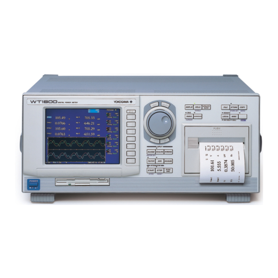
Chapter 2 Names and Uses of Parts Front Panel, Rear Panel, and Top View Front Panel ESC key Jog shuttle Clears and escapes from Used when selecting setup parameters and setting values. the current menu. (Section 2.2) DIGITAL POWER METER UPDATE DISPLAY HOLD... - Page 51 2.1 Front Panel, Rear Panel, and Top View Top View Rear Panel ..Vent holes (Section 3.2) (Vent holes are also present on the bottom side.) Front Panel IM 760101-01E...
-
Page 52: Operation Keys, Jog Shuttle
Operation Keys, Jog Shuttle Common to All Functions ESC key Clears and escapes from the current menu. RESET key Press this key to reset the value to default. SELECT key Confirms the selection made using the jog shuttle or the set value. SHIFT key UPDATE DISPLAY... - Page 53 2.2 Operation Keys, Jog Shuttle Set Integration and Harmonics Measurement UPDATE HOLD FILE STORE COPY DISPLAY RATE STORE SET MENU SINGLE TRIG'D REMOTE WAVE LOCAL MISC HARMONICS MAX HOLD NULL CURSOR SHIFT HARMONICS key Sets various parameters for harmonic measurement. (Sections 7.1 and 7.3 to 7.7) INPUT START key...
- Page 54 2.2 Operation Keys, Jog Shuttle Store and Recall Data, Save and Load Data, Set Ethernet Communications and Other Functions FILE key Formats disks, saves setup parameters, waveform display data, numerical data, and screen image data, loads setup parameters, changes file attributes, deletes files, copies files, renames directories/files, and creates directories.
-
Page 55: Chapter 3 Before Starting Measurements
Do not remove the case from the instrument. Some sections inside the instrument have high voltages that are extremely dangerous. For internal inspection or adjustment, contact your nearest YOKOGAWA dealer. Abnormal Behavior Stop using the instrument if there are any symptoms of trouble such as strange odors or smoke coming from the instrument. -
Page 56: Installing The Instrument
Installing the Instrument Installation Conditions Install the instrument in a place that meets the following conditions. Flat, Even Surface If the instrument is not installed on a stable horizontal surface, the printer’s recording quality may degrade and precise measurements may be impeded. Well-Ventilated Location Vent holes are located on the top and bottom of the instrument. - Page 57 3.2 Installing the Instrument Installation Position Desktop Place the instrument on a flat, even surface as shown in the figure below. If the instrument is installed in a horizontal position, rubber feet can be attached to prevent slipping. Two sets (four pieces) of rubber feet are included in the package. Rack Mount To rack mount the instrument, use the rack mount kit that is sold separately.
-
Page 58: Wiring Precautions
Wiring Precautions To prevent the possibility of electric shock and damage to the instrument, follow the warnings below. WARNING • Employ protective earth ground before connecting measurement cables. • Turn OFF the power to the measurement circuit, when wiring the circuit. Connecting or removing measurement cables while the power is turned ON is dangerous. - Page 59 3.3 Wiring Precautions • To make the protective functions effective, check the following items before applying the voltage or current of the circuit under measurement. • The power cable provided with the instrument is used to connect to the power supply and the instrument is grounded.
-
Page 60: For Making Accurate Measurements
LOAD ± ± ± ± Input terminal (ELEMENT) WT1600 As a reference, the relationship of the voltages and currents that produce effects of 0.1%, 0.01%, and 0.001% are shown in the figure below. 0.1% Effect 0.01% Effect 1000 Smaller effect 0.001% Effect... - Page 61 3.4 For Making Accurate Measurements Effects of Stray Capacitance The effects of stray capacitance on the measurement accuracy can be minimized by connecting the current input terminal of the instrument to the side that is close to the earth potential of the power source (SOURCE). The internal structure of the instrument is as follows.
-
Page 62: Connecting The Power Supply
OFF. • To prevent the possibility of electric shock or fire, always use the power cord supplied by YOKOGAWA. • Make sure to perform protective grounding to prevent the possibility of electric shock. Connect the power cord to a three-pin power outlet with a protective earth terminal. -
Page 63: Directly Wiring The Circuit Under Measurement
Directly Wiring the Circuit under Measurement The measurement cable is wired directly from the circuit under measurement to the voltage/current input terminal. To prevent the possibility of electric shock and damage to the instrument, follow the precautions given in section 3.3, “Wiring Precautions.” Connecting to the Input Terminal •... - Page 64 3.6 Directly Wiring the Circuit under Measurement Note • After wiring, the wiring system must be selected. See section 5.1, “Selecting the Wiring System.” • The thick lines on the wiring diagrams are the sections where the current flows. Use appropriate wires that are suitable for the current.
- Page 65 3.6 Directly Wiring the Circuit under Measurement Wiring Example of a Three-Phase, Three-Wire System (3P3W) • If there are six input elements, three three-phase, three-wire systems can be set up (elements 1 and 2, elements 3 and 4, and elements 5 and 6). •...
-
Page 66: Using An External Current Sensor To Wire The Circuit Under Measurement
Using an External Current Sensor to Wire the Circuit under Measurement To prevent the possibility of electric shock and damage to the instrument, follow the precautions given in section 3.3, “Wiring Precautions.” • As shown below, when the maximum current value of the circuit under measurement exceeds the maximum range of the input element, an external sensor can be connected to the current sensor input connector in order to measure the current of the circuit under measurement. - Page 67 Shunt-type current sensor Area of space created by the connection wires OUT H External sensor cable WT1600 ± Shielded wire OUT L • For a shunt-type current sensor, connect it to the power earth ground side as shown in the figure below.
- Page 68 3.7 Using an External Current Sensor to Wire the Circuit under Measurement The following wiring examples are for connecting shunt-type current sensors. When connecting a clamp-type current sensor, replace the shunt-type current sensor with the clamp-type. In addition, the assignment of elements to the input terminals in the following figure varies depending on the number of installed input elements.
- Page 69 3.7 Using an External Current Sensor to Wire the Circuit under Measurement Wiring Example of a Three-Voltage, Three-Current System (3V3A) Using a Shunt-Type Current Sensor SOURCE LOAD ± ± OUT H OUT L ± OUT H OUT L OUT L OUT H Input Input...
-
Page 70: Using An External Pt Or Ct To Wire The Circuit Under Measurement
Using an External PT or CT to Wire the Circuit under Measurement Connect a measurement cable from an external potential transformer (PT) or current transformer (CT) to the voltage or current input terminal of the input element. To prevent the possibility of electric shock and damage to the instrument, follow the precautions given in section 3.3, “Wiring Precautions.”... - Page 71 3.8 Using an External PT or CT to Wire the Circuit under Measurement Note • After wiring, the wiring system must be selected. See section 5.1, “Selecting the Wiring System.” • The thick lines on the wiring diagrams are the sections where the current flows. Use appropriate wires that are suitable for the current.
- Page 72 3.8 Using an External PT or CT to Wire the Circuit under Measurement Wiring Example of a Three-Phase, Three-Wire System (3P3W) Using PT and CT LOAD SOURCE L CT L CT ± ± ± ± Input terminal 1 Input terminal 2 Wiring Example of a Three-Voltage, Three-Current System (3V3A) Using PT and CT LOAD SOURCE...
-
Page 73: Wiring A Circuit With Voltage Input Exceeding 600 V
Wiring a Circuit with Voltage Input Exceeding 600 V When the voltage across the voltage input terminals exceeds 600 V, do not directly input the current to the current input terminals. Connect the output of an isolation sensor (CT, DT-CT, or clamp) to the current sensor input connector. WARNING •... -
Page 74: Turning On/Off The Power Switch
If the power switch is turned ON while pressing RESET, the setup parameters are initialized to their factory default values. For information on initialization, see section 15.3, “Initializing the Settings.” If the instrument still does not work after checking these points, contact your nearest YOKOGAWA dealer for repairs. 3-20 IM 760101-01E... - Page 75 ON. When this message appears frequently, the battery must be replaced quickly. The user cannot replace the battery. For battery replacement, contact your nearest YOKOGAWA dealer. For information regarding battery life, see section 16.6. 3-21 IM 760101-01E...
-
Page 76: Setting The Date And Time
3.11 Setting the Date and Time Keys UP DATE DISPLAY HOLD FILE STORE COPY RATE SINGLE STORE SET MENU TRIG'D REMOTE WAVE LOCAL MISC HARMONICS CURSOR MAX HOLD NULL SHIFT To exit the menu during operation, press ESC. INPUT RANGE SCALING WIRING MOTOR SET... - Page 77 3.11 Setting the Date and Time Explanation • Turning ON/OFF the Date/Time display You can select whether or not to display the date and time in the lower right corner of the screen. • OFF: Do not display the date and time. •...
-
Page 78: Entering Values And Strings
3.12 Entering Values and Strings Entering Values After selecting the setup parameter with the SELECT key and soft keys, the value can be changed using the jog shuttle. The outer shuttle ring can be used step through the values in large increments. On some parameters, the arrow keys below the jog shuttle can be used to move among the digits. - Page 79 3.12 Entering Values and Strings • Entering the equation for the user-defined function The following figure shows the keyboard that appears when setting the equation for the user-defined function. Long equations can be temporarily held in the internal memory so that it can be used in other equations. •...
- Page 80 3.12 Entering Values and Strings • Enter the file name and comment (such as the server name, user name, password, and e-mail address for Ethernet communication) The following figure shows the keyboard that appears when setting the file name or comment.
- Page 81 3.12 Entering Values and Strings • Keys other than the character keys • BS: Deletes the character before the entry position. • INS: Switches the insert/overwrite mode. During the insert mode, the INSERT indicator on the keyboard lights. When a new character is entered in the insert mode, the new character is placed at the entry position and all following characters are moved backward.
-
Page 82: Chapter 4 Screen Display Format
Chapter 4 Screen Display Format Displaying the Data (Numerical Data) of Measurement Functions «For a functional description, see section 1.4.» Keys UP DATE DISPLAY HOLD FILE STORE COPY RATE SINGLE STORE SET MENU TRIG'D REMOTE WAVE LOCAL MISC HARMONICS CURSOR MAX HOLD NULL SHIFT... - Page 83 4.1 Displaying the Data (Numerical Data) of Measurement Functions The following procedures are given for a representative example in which the display format is set to Numeric. During Normal Measurement Selecting the Displayed Item Press the Item Amount soft key to display the Item Amount menu. Press one of the 4(2) to All keys to select the number of displayed items.
- Page 84 4.1 Displaying the Data (Numerical Data) of Measurement Functions Page Scrolling the Display Press the Page Up Scroll Exec or Page Down Scroll Exec soft key to scroll the page. • If you press the Page Up Scroll Exec soft key, the numerical data corresponding to item numbers that are smaller than those of the numerical data of measurement functions displayed up to that point are displayed.
- Page 85 4.1 Displaying the Data (Numerical Data) of Measurement Functions During Harmonic Measurement Selecting the Number of Displayed Items or List Display Press the Item Amount soft key to display the Item Amount menu. Select one of the 4(2) to ΣList soft keys to select the number of displayed items or list display.
- Page 86 4.1 Displaying the Data (Numerical Data) of Measurement Functions Page Scrolling the Display • When 4(2) through 16(8) is selected in step 6 Press the Page Up Scroll Exec or Page Down Scroll Exec soft key to scroll the page. •...
- Page 87 4.1 Displaying the Data (Numerical Data) of Measurement Functions Explanation A display example is shown below. For the procedure in changing the displayed items and contents of numerical data, see chapters 6, 7, and 8. The color changes from green to red when the input signal level exceeds approx.
- Page 88 4.1 Displaying the Data (Numerical Data) of Measurement Functions Selecting the Display Format Select the display format of the numerical data from the following list of choices. [-------] (no data) is displayed in places where the measurement function is not selected or where no numerical data is present.
- Page 89 4.1 Displaying the Data (Numerical Data) of Measurement Functions During Harmonic Measurement Meaning of the Measurement Function Symbols • For the meanings of the measurement function symbols that are displayed, see section 1.2, “Measurement Functions and Measurement Periods,” 1.5, “Computation,” and appendix 1, “Symbols and Determination of Measurement Functions.”...
- Page 90 4.1 Displaying the Data (Numerical Data) of Measurement Functions • Single List • When the display format is Numeric, 48 numerical data values for a single measurement function are displayed in two columns. • When the display format is other than Numeric, 22 numerical data values for a single measurement function are displayed in two columns.
-
Page 91: Displaying Waveforms
Displaying Waveforms «For a functional description, see section 1.7.» Keys UP DATE DISPLAY HOLD FILE STORE COPY RATE SINGLE STORE SET MENU TRIG'D REMOTE WAVE LOCAL MISC HARMONICS CURSOR MAX HOLD NULL SHIFT To exit the menu during operation, press ESC. INPUT RANGE SCALING... - Page 92 4.2 Displaying Waveforms Explanation A display example is shown below. For the procedure in changing the displayed items and contents of waveforms, see chapter 9. Distinction of voltage or current, the element, and the upper limit of the displayed waveform Distinction of voltage or current, the element, and the lower limit of the displayed waveform...
-
Page 93: Displaying Bar Graphs
Displaying Bar Graphs «For a functional description, see section 1.8.» Keys UP DATE DISPLAY HOLD FILE STORE COPY RATE SINGLE STORE SET MENU TRIG'D REMOTE WAVE LOCAL MISC HARMONICS CURSOR MAX HOLD NULL SHIFT To exit the menu during operation, press ESC. INPUT RANGE SCALING... - Page 94 4.3 Displaying Bar Graphs Explanation A display example is shown below. For the procedure in changing the displayed items and contents of bar graphs, see section 7.9. When the vertical axis is set to logarithmic coordinates, the characters <log Scale> appears at the upper left corner of the screen. Range of orders of the displayed bar graph Distinction of voltage or current,...
-
Page 95: Displaying Vectors
Displaying Vectors «For a functional description, see section 1.8.» Keys UP DATE DISPLAY HOLD FILE STORE COPY RATE SINGLE STORE SET MENU TRIG'D REMOTE WAVE LOCAL MISC HARMONICS CURSOR MAX HOLD NULL SHIFT To exit the menu during operation, press ESC. INPUT RANGE SCALING... -
Page 96: Displaying Trends
Displaying Trends «For a functional description, see section 1.8.» Keys UP DATE DISPLAY HOLD FILE STORE COPY RATE SINGLE STORE SET MENU TRIG'D REMOTE WAVE LOCAL MISC HARMONICS CURSOR MAX HOLD NULL SHIFT To exit the menu during operation, press ESC. INPUT RANGE SCALING... - Page 97 4.5 Displaying Trends Explanation A display example is shown below. For the procedure in changing the displayed items and contents of trends, see chapter 10. When the retrieval of waveform display data is OFF (see section 9.1) during normal measurement, the horizontal axis is expressed using time as shown below.
-
Page 98: Listing The Setup Parameters
Listing the Setup Parameters Keys UP DATE DISPLAY HOLD FILE STORE COPY RATE SINGLE STORE SET MENU TRIG'D REMOTE WAVE LOCAL MISC HARMONICS CURSOR MAX HOLD NULL SHIFT To exit the menu during operation, press ESC. INPUT RANGE SCALING WIRING MOTOR SET FILTER MEASURE... - Page 99 4.6 Listing the Setup Parameters Displaying the Relation Table of Elements and Measurement Ranges Press the Power Element soft key. The relation table of measurement ranges, input filters, transformation ratios, scaling factors, and other parameters are displayed for each element. Displaying the Relation Table of Trend Targets and Measurement Functions Press the Trend soft key to display the relation table of trend targets and measurement functions.
- Page 100 4.6 Listing the Setup Parameters Relation Table of Trend Targets and Measurement Functions Relation Table of D/A Output Channels and Measurement Functions Displayed only on products with the D/A output (option). Relation Table of the Rotating Speed of Motor Evaluation Function (Option) and Input Ranges of Torque Displayed only to products with the motor evaluation function (option).
-
Page 101: Chapter 5 Measurement Conditions
Chapter 5 Measurement Conditions Selecting the Wiring System «For a functional description, see section 1.3.» Keys UP DATE DISPLAY HOLD FILE STORE COPY RATE SINGLE STORE SET MENU TRIG'D REMOTE WAVE LOCAL MISC HARMONICS CURSOR MAX HOLD NULL SHIFT To exit the menu during operation, press ESC. INPUT RANGE SCALING... - Page 102 5.1 Selecting the Wiring System Selecting the Wiring System • The procedure described here is not necessary, if the wiring system of all elements was set to 1P2W (single-phase, two-wire) in the previous section “Selecting the Wiring System Pattern.” • Two types of wiring systems that use two elements are available: 1P3W (single- phase, three-wire) and 3P3W (three-phase, three-wire).
- Page 103 5.1 Selecting the Wiring System Explanation • The selectable wiring systems vary depending on the number of input elements that are installed in the instrument. You may be able to select only a single type of wiring system or two or three types of wiring systems. You can select the wiring system from the following five types.
-
Page 104: Setting The Measurement Range During Direct Input
Setting the Measurement Range during Direct Input «For a functional description, see section 1.3.» Keys UP DATE DISPLAY HOLD FILE STORE COPY RATE SINGLE STORE SET MENU TRIG'D REMOTE WAVE HARMONICS LOCAL MISC CURSOR MAX HOLD NULL SHIFT To exit the menu during operation, press ESC. INPUT RANGE SCALING... - Page 105 5.2 Setting the Measurement Range during Direct Input Setting the Current Range • Selecting the current input terminal Press the Terminal soft key to select Direct. • Setting the current range Press the I Range Up Exec or I Range Down Exec soft key to set the current range.
- Page 106 5.2 Setting the Measurement Range during Direct Input Explanation Display Position of the Target Element and the Specified Range The target element and the specified range are displayed at the upper right corner of the screen when RANGE is pressed. Element Voltage range Appears when in auto range mode...
- Page 107 5.2 Setting the Measurement Range during Direct Input • Range increase • When the data of measurement function Urms or Irms exceeds 110% of the current measurement range, the range is increased. • When the peak value of the input signal exceeds 330% or 660% of the current measurement range when the crest factor is set to 3 or 6, respectively, the range is increased.
- Page 108 5.2 Setting the Measurement Range during Direct Input The combinations of the actual voltage and current ranges and the power range are listed below according to the table on the previous page (when the voltage or current range of each element is set to the same range). The table shows the active power range (unit: W).
- Page 109 5.2 Setting the Measurement Range during Direct Input • When the crest factor is set to 6 Effective Power Range of the Wiring Unit of Wiring System 1P2W or Each Element Current Voltage Range [V] Range 750m 1.5000 3.0000 5.0000 7.5000 15.000 30.000...
-
Page 110: Setting The Measurement Range When Using An External Current Sensor
Setting the Measurement Range When Using an External Current Sensor «For a functional description, see section 1.3.» Keys UP DATE DISPLAY HOLD FILE STORE COPY RATE SINGLE STORE SET MENU TRIG'D REMOTE WAVE HARMONICS LOCAL MISC CURSOR MAX HOLD NULL SHIFT To exit the menu during operation, press ESC. - Page 111 5.3 Setting the Measurement Range When Using an External Current Sensor Copying the Current Sensor Range The current sensor range specified for a given element can be set to the elements of the same wiring unit. The voltage range (see section 5.1) is also copied. The current sensor range for other elements that were specified before is not held.
- Page 112 5.3 Setting the Measurement Range When Using an External Current Sensor • Copying the current sensor transformation ratio The current sensor transformation ratio specified for a given element can be set to the elements of the same wiring unit. The ON/OFF condition, PT ratio, CT ratio, and power coefficient (see section 5.4) of the scaling function area also copied.
- Page 113 5.3 Setting the Measurement Range When Using an External Current Sensor Copying the Current Sensor Range The current sensor range specified for a given element can be set to the elements of the same wiring unit. However, if the wiring system is pattern 1, the measurement range can be copied to all other elements.
-
Page 114: Setting The Scaling Function When Using An External Pt Or Ct
Setting the Scaling Function When Using an External PT or CT «For a functional description, see section 1.3.» Keys UP DATE DISPLAY HOLD FILE STORE COPY RATE SINGLE STORE SET MENU TRIG'D REMOTE WAVE HARMONICS LOCAL MISC CURSOR MAX HOLD NULL SHIFT To exit the menu during operation, press ESC. - Page 115 5.4 Setting the Scaling Function When Using an External PT or CT Setting the CT Ratio Press the Ct Ratio soft key. Turn the jog shuttle to set the CT ratio. For the procedures on how to enter values using the jog shuttle, see section 3.12, “Entering Values and Strings.”...
- Page 116 5.4 Setting the Scaling Function When Using an External PT or CT Explanation Measurements can be made by connecting the output of the secondary side of the PT and the output of the secondary side of the CT to the same voltage and current input terminals that are used when directly inputting a signal.
-
Page 117: Selecting The Input Filter
Selecting the Input Filter «For a functional description, see section 1.3.» Keys UP DATE DISPLAY HOLD FILE STORE COPY RATE SINGLE STORE SET MENU TRIG'D REMOTE WAVE LOCAL MISC HARMONICS CURSOR MAX HOLD NULL SHIFT To exit the menu during operation, press ESC. INPUT RANGE SCALING... - Page 118 5.5 Selecting the Input Filter Copying the Input Filter The input filter specified for a given element can be set to the elements of the same wiring unit. The input filters for other elements that were specified before is not held. Press one of the soft keys corresponding to the displayed element from which the information is to be copied (the copy source).
-
Page 119: Averaging
Averaging «For a functional description, see section 1.3.» Keys UP DATE DISPLAY HOLD FILE STORE COPY RATE SINGLE STORE SET MENU TRIG'D REMOTE WAVE LOCAL MISC HARMONICS CURSOR MAX HOLD NULL SHIFT To exit the menu during operation, press ESC. INPUT RANGE SCALING... - Page 120 5.6 Averaging During Harmonic Measurement If Mode is turned ON in the Harmonics menu (see section 7.1), the instrument enters the harmonic measurement mode. Press AVG to display the Avg menu. Turning ON/OFF the Averaging Function Press the Averaging soft key to select ON or OFF. Explanation The averaging function is effective when reading of the numerical display is difficult due to fluctuations.
- Page 121 5.6 Averaging During Harmonic Measurement If Mode is turned ON in the Harmonics menu (see section 7.1), the instrument enters the harmonic measurement mode. When the fundamental frequency is 50/60 Hz, the attenuation constant is automatically adjusted so that a first-order low-pass filter with a time constant of 1.5 s is achieved. Exponential averaging is performed using this attenuation constant.
-
Page 122: Changing The Data Update Rate
Changing the Data Update Rate «For a functional description, see section 1.3.» Keys UP DATE DISPLAY HOLD FILE STORE COPY RATE SINGLE STORE SET MENU TRIG'D REMOTE WAVE LOCAL MISC HARMONICS CURSOR MAX HOLD NULL SHIFT To exit the menu during operation, press ESC. INPUT RANGE SCALING... - Page 123 5.7 Changing the Data Update Rate Explanation The data update rate refers to the interval in which the sampled data used to determine the measurement functions is retrieved. When the retrieval of waveform display data is OFF during normal measurement, the D/A output, communication output, or storing (to the internal memory) of the numerical data is carried out using this interval.
-
Page 124: Holding The Display And Performing Single Measurements
Holding the Display and Performing Single Measurements «For a functional description, see section 1.3.» Keys UP DATE DISPLAY HOLD FILE STORE COPY RATE SINGLE STORE SET MENU TRIG'D REMOTE WAVE HARMONICS LOCAL MISC CURSOR MAX HOLD NULL SHIFT To exit the menu during operation, press ESC. INPUT RANGE SCALING... -
Page 125: Holding The Numerical Data Display At The Maximum
Holding the Numerical Data Display at the Maximum «For a functional description, see section 1.3.» Keys UP DATE DISPLAY HOLD FILE STORE COPY RATE SINGLE STORE SET MENU TRIG'D REMOTE WAVE LOCAL MISC HARMONICS CURSOR MAX HOLD NULL SHIFT To exit the menu during operation, press ESC. INPUT RANGE SCALING... -
Page 126: Performing Master/Slave Synchronized Measurements
5.10 Performing Master/Slave Synchronized Measurements «For a functional description, see section 1.3.» Keys UP DATE DISPLAY HOLD FILE STORE COPY RATE SINGLE STORE SET MENU TRIG'D REMOTE WAVE HARMONICS LOCAL MISC CURSOR MAX HOLD NULL SHIFT To exit the menu during operation, press ESC. INPUT RANGE SCALING... - Page 127 5.10 Performing Master/Slave Synchronized Measurements Explanation With the master instrument outputting measurement start and stop signals and the slave instrument receiving those signals, synchronized measurement on two instruments is achieved. External Start/Stop Signal Input/Output Connector Connect the external start signal input/output connectors on the rear panel between the master and slave instruments using BNC connectors (sold separately) and do the same for the external stop signal input/output connectors.
- Page 128 5.10 Performing Master/Slave Synchronized Measurements Input Circuit for the External Start/Stop Signal and Time Chart +5 V 100 Ω Start/Stop input signal Minimum pulse width Start/Stop input signal Input delay time Measurement start Trigger occurrence CAUTION • When the instrument is set to master, do not apply external voltage to the external start/stop signal input/output connector (START/STOP).
-
Page 129: Selecting The Crest Factor
5.11 Selecting the Crest Factor Keys UP DATE DISPLAY HOLD FILE STORE COPY RATE SINGLE STORE SET MENU TRIG'D REMOTE WAVE LOCAL MISC HARMONICS CURSOR MAX HOLD NULL SHIFT To exit the menu during operation, press ESC. INPUT RANGE SCALING WIRING MOTOR SET FILTER... -
Page 130: Chapter 6 Normal Measurement And Integration
Chapter 6 Normal Measurement and Integration Changing the Displayed Item of Numerical Data «For a functional description, see section 1.4.» Keys UP DATE DISPLAY HOLD FILE STORE COPY RATE SINGLE STORE SET MENU TRIG'D REMOTE WAVE LOCAL MISC HARMONICS CURSOR MAX HOLD NULL SHIFT... - Page 131 6.1 Changing the Displayed Item of Numerical Data The following procedures are given for a representative example in which the display format is set to Numeric. Press the Numeric Disp Items soft key to display the Numeric Items menu. Selecting the Item to Be Changed Turn the jog shuttle to select the item to be changed.
- Page 132 6.1 Changing the Displayed Item of Numerical Data Explanation Changing the measurement function • The types of measurement functions that can be selected are the items that are indicated in “Measurement Function Types during Normal Measurement” and “Measurement Function Types for Motor Evaluation Function (Option)” in section 1.2;...
-
Page 133: Setting The Measurement Period
Setting the Measurement Period «For a functional description, see section 1.2.» Keys UP DATE DISPLAY HOLD FILE STORE COPY RATE SINGLE STORE SET MENU TRIG'D REMOTE WAVE LOCAL MISC HARMONICS CURSOR MAX HOLD NULL SHIFT To exit the menu during operation, press ESC. INPUT RANGE SCALING... - Page 134 6.2 Setting the Measurement Period Copying the Synchronization Source The synchronization source specified for a given element can be set to the elements of the same wiring unit. The synchronization source for other elements that were specified before is not held. Press one of the soft keys corresponding to the displayed element from which the information is to be copied (the copy source).
-
Page 135: Harmonic Measurement
6.2 Setting the Measurement Period Measurement Period • The measurement period is set between the first point where the synchronization source crosses the level zero point (center of the amplitude) on the rising slope (or falling slope) within the data update interval and the last point where the synchronization source crosses the level zero point (center of the amplitude) on the rising slope (or falling slope) within the update interval. -
Page 136: Selecting The Frequency Measurement Target
Selecting the Frequency Measurement Target «For a functional description, see section 1.2.» Keys UP DATE DISPLAY HOLD FILE STORE COPY RATE SINGLE STORE SET MENU TRIG'D REMOTE WAVE LOCAL MISC HARMONICS CURSOR MAX HOLD NULL SHIFT To exit the menu during operation, press ESC. INPUT RANGE SCALING... -
Page 137: Setting The User-Defined Function
Setting the User-Defined Function «For a functional description, see section 1.5.» Keys UP DATE DISPLAY HOLD FILE STORE COPY RATE SINGLE STORE SET MENU TRIG'D REMOTE WAVE LOCAL MISC HARMONICS CURSOR MAX HOLD NULL SHIFT To exit the menu during operation, press ESC. INPUT RANGE SCALING... - Page 138 6.4 Setting the User-Defined Function Setting the Unit Turn the jog shuttle to select Unit. Press SELECT to display the keyboard. Use the keyboard to set the unit. For keyboard operations, see section 3.12, “Entering Values and Strings.” Setting the Equation Turn the jog shuttle to select Expression.
- Page 139 6.4 Setting the User-Defined Function Setting the Equation The combination of the measurement function and element number (Urms1, for example) can be used as an operand to create up to four equations (F1 to F4). There can be up to 16 operands in one equation. •...
- Page 140 6.4 Setting the User-Defined Function • Operators The following operators can be used to create the equation. Operator Example Description +, –, ∗, / URMS(E1)+URMS(E2) Basic arithmetic of the measurement functions ABS(UMN(E1)–UMN(E2)) Absolute value of the measurement function SQR(IDC(E1)) Square of the measurement function SQRT SQRT(ABS(IDC(E1))) Square root of the measurement function...
-
Page 141: Setting The Delta Computation
Setting the Delta Computation «For a functional description, see section 1.5.» Keys UP DATE DISPLAY HOLD FILE STORE COPY RATE SINGLE STORE SET MENU TRIG'D REMOTE WAVE LOCAL MISC HARMONICS CURSOR MAX HOLD NULL SHIFT To exit the menu during operation, press ESC. INPUT RANGE SCALING... - Page 142 6.5 Setting the Delta Computation Explanation In the normal measurement mode, the sum or difference of the instantaneous values (sampled data) of the voltage or current between the elements assigned to the target wiring unit for the delta computation can be used to determine the measurement functions, ∆U (∆Urms, ∆Umn, ∆Udc ∆Uac), ∆I (∆Irms, ∆Imn, ∆Idc, ∆Iac).
- Page 143 6.5 Setting the Delta Computation • Star>Delta Using the data from a three-phase, four-wire system, the various data of a delta connection are computed from the data of a star connection (start-delta transformation). ∆U1 (∆Urms1, ∆Umn1, ∆Udc1, ∆Uac1) ∆U2 (∆Urms2, ∆Umn2, ∆Udc2, ∆Uac2) ∆U3 (∆Urms3, ∆Umn3, ∆Udc3, ∆Uac3) ∆I4 (∆Irms4, ∆Imn4, ∆Idc4, ∆Iac4) ±...
-
Page 144: Setting The Equations For Apparent Power And Corrected Power
Setting the Equations for Apparent Power and Corrected Power «For a functional description, see section 1.5.» Keys UP DATE DISPLAY HOLD FILE STORE COPY RATE SINGLE STORE SET MENU TRIG'D REMOTE WAVE LOCAL MISC HARMONICS CURSOR MAX HOLD NULL SHIFT To exit the menu during operation, press ESC. - Page 145 6.6 Setting the Equations for Apparent Power and Corrected Power Setting the Equation for Corrected Power Press the Pc Formula soft key to display the Pc Formula dialog box. • Selecting the applicable standard Turn the jog shuttle to select the standard for Pc Formula. Press SELECT to select either IEC76-1(1976), IEEE C57.12.90-1993 or IEC76- 1(1993).
- Page 146 6.6 Setting the Equations for Apparent Power and Corrected Power Explanation Selecting the Equation for Apparent Power The apparent power, in the normal measurement mode, can be determined by the product of the voltage (Urms, Umean, and Udc) and current (Irms, Imean, and Idc). There are three types of voltages and currents when measuring in the normal measurement mode.
-
Page 147: Selecting The Display Format Of The Phase Difference
Selecting the Display Format of the Phase Difference «For a functional description, see section 1.5.» Keys UP DATE DISPLAY HOLD FILE STORE COPY RATE SINGLE STORE SET MENU TRIG'D REMOTE WAVE HARMONICS LOCAL MISC CURSOR MAX HOLD NULL SHIFT To exit the menu during operation, press ESC. INPUT RANGE SCALING... - Page 148 6.7 Selecting the Display Format of the Phase Difference Explanation Select the display format of the phase difference φ of the voltage and current from the following list of choices. This is valid during the normal measurement mode. • 180 Lead/Lag With the positive vertical axis set to zero degrees, this format displays φ...
-
Page 149: Setting The Normal Integration Mode And The Integration Timer
You can set the individual element integration through key operation, but the execution of integration can only be done through communication commands. Even if Independent Control is set to ON (individual element integration ON), the WT1600 operates in the same fashion as when Independent Control is OFF (individual element integration OFF). - Page 150 6.8 Setting the Normal Integration Mode and the Integration Timer Setting the Integration Timer during All Element Simultaneous Computation (Independent Control OFF) Press the Timer Setting soft key to display the Timer Setting dialog box. Turn the jog shuttle to select one of the hour, minute, and second boxes. Press SELECT.
- Page 151 6.8 Setting the Normal Integration Mode and the Integration Timer Explanation To perform integration, the integration mode and integration time must be set before starting the operation. This section will describe how to set the normal integration mode and the integration time. For the procedure in starting the integration, see section 6.11. Selecting the Normal Integration Mode or Repetitive Integration Mode In this mode, the integration time is set in relative time and the integration is performed over the specified time.
-
Page 152: Setting The Real-Time Integration Mode, The Integration Timer, And The Reservation Time
You can set the individual element integration through key operation, but the execution of integration can only be done through communication commands. Even if Independent Control is set to ON (individual element integration ON), the WT1600 operates in the same fashion when Independent Control is OFF (individual element integration OFF). - Page 153 6.9 Setting the Real-time Integration Mode, the Integration Timer, and the Reservation Time Setting the Integration Timer during All Element Simultaneous Computation (Independent Control OFF) Press the Timer Setting soft key to display the Timer Setting dialog box. Turn the jog shuttle to select one box from hour, minute, and second. Press SELECT.
- Page 154 6.9 Setting the Real-time Integration Mode, the Integration Timer, and the Reservation Time Setting the Integration Timer during Individual Element Computation (Independent Control ON) Press the Timer Setting soft key to display the Independent Timer Setting dialog box. Turn the jog shuttle to select Setting. Press SELECT to select Each or All.
- Page 155 6.9 Setting the Real-time Integration Mode, the Integration Timer, and the Reservation Time Setting the Reservation Time during Individual Element Computation (Independent Control ON) Press the Real Time Control soft key to display the Independent Real Time Control dialog box. Turn the jog shuttle to select one of the reservation year, month, date, hour, minute, and second boxes for specifying when the integration operation will start.
- Page 156 6.9 Setting the Real-time Integration Mode, the Integration Timer, and the Reservation Time Explanation To perform integration, the integration mode and integration time must be set before starting the operation. This section will describe how to set the normal integration mode and the integration time for real-time control.
- Page 157 6.9 Setting the Real-time Integration Mode, the Integration Timer, and the Reservation Time Setting the Reservation Time • The reservation time is set in units of year:month:date, hour:minute:second. Set the hour:minute:second in the following range. 00:00:00 to 23:59:59 • When performing all element simultaneous integration by turning Independent Control OFF, a single reservation time can be specified.
-
Page 158: Selecting The Current Mode For Current Integration And On/Off Of Integration Auto Calibration
6.10 Selecting the Current Mode for Current Integration and ON/OFF of Integration Auto Calibration «For a functional description, see section 1.6.» Keys UP DATE DISPLAY HOLD FILE STORE COPY RATE SINGLE STORE SET MENU TRIG'D REMOTE WAVE HARMONICS LOCAL MISC CURSOR MAX HOLD NULL... - Page 159 6.10 Selecting the Current Mode for Current Integration and ON/OFF of Integration Auto Calibration Turning ON/OFF the Integration Auto Calibration Press the Auto Cal soft key to select ON or OFF. Explanation Selecting the Current Mode for Current Integration • Select the current type used for current integration on each element from the following list of choices.
-
Page 160: Performing Integration (Start, Stop, And Reset)
6.11 Performing Integration (Start, Stop, and Reset) «For a functional description, see section 1.6.» Keys UP DATE DISPLAY HOLD FILE STORE COPY RATE SINGLE STORE SET MENU TRIG'D REMOTE WAVE LOCAL MISC HARMONICS CURSOR MAX HOLD NULL SHIFT To exit the menu during operation, press ESC. INPUT RANGE SCALING... - Page 161 6.11 Performing Integration (Start, Stop, and Reset) Performing Integration in the Normal Integration Mode Check that the integration mode is set to normal integration or repetitive integration (Continuous). See section 6.8. Check that the integration timer is set to some value other than 0000:00:00. See section 6.8.
- Page 162 6.11 Performing Integration (Start, Stop, and Reset) Performing Integration in the Real-time Integration Mode Check that the integration mode is set to real-time normal integration (R-Normal) or real-tie repetitive integration (R-Continuous). See section 6.9. Check that the integration timer and the reservation time are specified. See section 6.9.
- Page 163 You can set the individual element integration through key operation, but the execution of integration can only be done through communication commands. Even if Independent Control is set to ON (individual element integration ON), the WT1600 operates in the same fashion when Independent Control is OFF (individual element integration OFF).
- Page 164 6.11 Performing Integration (Start, Stop, and Reset) • If the integration is stopped while the display is held, the display and communication output values do not change from the held values. When the hold function is released (OFF) or a single measurement (by pressing HOLD (SINGLE) after pressing SHIFT) is made, the integration result at the time the integration was stopped is displayed or output via communications.
-
Page 165: Chapter 7 Harmonic Measurement
6.11 Performing Integration (Start, Stop, and Reset) Integration When Current Input Is Small If Irms or Iac is less than or equal to 0.3% (less than or equal to 0.6% when the crest factor is set to 6) and Imn is less than or equal to 1% (less than or equal to 2% when the crest factor is set to 6) of the measurement range, the current is considered to be zero for the purpose of integration. -
Page 166: Setting The Harmonic Measurement Mode
Chapter 7 Harmonic Measurement Setting the Harmonic Measurement Mode Keys UP DATE DISPLAY HOLD FILE STORE COPY RATE SINGLE STORE SET MENU TRIG'D REMOTE WAVE LOCAL MISC HARMONICS CURSOR MAX HOLD NULL SHIFT To exit the menu during operation, press ESC. INPUT RANGE SCALING... -
Page 167: Changing The Displayed Item Of Numerical Data
Changing the Displayed Item of Numerical Data «For a functional description, see section 1.4.» Keys UP DATE DISPLAY HOLD FILE STORE COPY RATE SINGLE STORE SET MENU TRIG'D REMOTE WAVE LOCAL MISC HARMONICS CURSOR MAX HOLD NULL SHIFT To exit the menu during operation, press ESC. INPUT RANGE SCALING... - Page 168 7.2 Changing the Displayed Item of Numerical Data The following procedures are given for a representative example in which the display format is set to Numeric. When Item Amount (Number of Displayed Items) Is Set to 4 (2), 8 (4), or 16 (8) Press the Numeric Disp Items soft key to display the Numeric Items menu.
- Page 169 7.2 Changing the Displayed Item of Numerical Data • Resetting the order of the displayed items Press the Reset List Exec soft key. The order of the displayed items is reset. Turn the jog shuttle to select OK or Cancel. Select OK and press SELECT to execute the reset of the order of the displayed items.
- Page 170 7.2 Changing the Displayed Item of Numerical Data • Changing the harmonic order Press ESC to return to the Display menu. Turn the jog shuttle to set the harmonic order. The display is scrolled, and the specified harmonic order and the numerical data are displayed. You can also page-scroll (see section 4.1).
- Page 171 7.2 Changing the Displayed Item of Numerical Data • Changing the harmonic order The harmonic order can be set to total or from dc (0th order) up to 100th order. Changing the measurement function of the third item Changing the element of the third item Changing the order When Item Amount (Number of Displayed Items) is set to Single List or Dual List...
-
Page 172: Selecting The Measurement Target
Selecting the Measurement Target Keys UP DATE DISPLAY HOLD FILE STORE COPY RATE SINGLE STORE SET MENU TRIG'D REMOTE WAVE LOCAL MISC HARMONICS CURSOR MAX HOLD NULL SHIFT To exit the menu during operation, press ESC. INPUT RANGE SCALING WIRING MOTOR SET FILTER MEASURE... -
Page 173: Selecting The Pll Source
Selecting the PLL Source «For a functional description, see section 1.2.» Keys UP DATE DISPLAY HOLD FILE STORE COPY RATE SINGLE STORE SET MENU TRIG'D REMOTE WAVE LOCAL MISC HARMONICS CURSOR MAX HOLD NULL SHIFT To exit the menu during operation, press ESC. INPUT RANGE SCALING... - Page 174 7.4 Selecting the PLL Source Explanation Set the PLL (phase locked loop) source that is used to determine the fundamental period, which acts as the reference in the analysis of the harmonic orders. Displayed Position of the Selected PLL Source The selected PLL source is displayed at the upper right corner of the screen when HARMONICS is pressed.
- Page 175 7.4 Selecting the PLL Source Note • The frequency of up to three signals including the signals selected for the PLL source as fU (voltage frequency) or fI (current frequency) can be measured. For the procedure in selecting the frequency measurement target, see section 6.3. If the number of frequency measurement targets exceeds three because you selected a PLL source other than the source selected in section 6.3, frequency measurement targets are removed in order from the element with the largest number in the order voltage and current.
-
Page 176: Setting The Harmonic Order To Be Analyzed
Setting the Harmonic Order to Be Analyzed Keys UP DATE DISPLAY HOLD FILE STORE COPY RATE SINGLE STORE SET MENU TRIG'D REMOTE WAVE LOCAL MISC HARMONICS CURSOR MAX HOLD NULL SHIFT To exit the menu during operation, press ESC. INPUT RANGE SCALING WIRING... - Page 177 7.5 Setting the Harmonic Order to Be Analyzed Explanation Select the range of harmonic orders that will be used to determine the numerical data of Total and the distortion factor of the harmonic waveform. For details on how to determine the data, see appendix 1. Selecting the Minimum Harmonic Order to Be Analyzed You can select from the following list of choices.
-
Page 178: Selecting The Equation For The Distortion Factor
Selecting the Equation for the Distortion Factor Keys UP DATE DISPLAY HOLD FILE STORE COPY RATE SINGLE STORE SET MENU TRIG'D REMOTE WAVE LOCAL MISC HARMONICS CURSOR MAX HOLD NULL SHIFT To exit the menu during operation, press ESC. INPUT RANGE SCALING WIRING... -
Page 179: Changing The Data Length
Changing the Data Length Keys UP DATE DISPLAY HOLD FILE STORE COPY RATE SINGLE STORE SET MENU TRIG'D REMOTE WAVE LOCAL MISC HARMONICS CURSOR MAX HOLD NULL SHIFT To exit the menu during operation, press ESC. INPUT RANGE SCALING WIRING MOTOR SET FILTER MEASURE... -
Page 180: Setting The User-Defined Function
Setting the User-Defined Function Keys UP DATE DISPLAY HOLD FILE STORE COPY RATE SINGLE STORE SET MENU TRIG'D REMOTE WAVE LOCAL MISC HARMONICS CURSOR MAX HOLD NULL SHIFT To exit the menu during operation, press ESC. INPUT RANGE SCALING WIRING MOTOR SET FILTER MEASURE... - Page 181 7.8 Setting the User-Defined Function Setting the Unit Turn the jog shuttle to select Unit. Press SELECT to display the keyboard. Use the keyboard to set the unit. For keyboard operations, see section 3.12, “Entering Values and Strings.” Setting the Equation Turn the jog shuttle to select Expression.
- Page 182 7.8 Setting the User-Defined Function Setting the Equation The combination of the measurement function, element number, and harmonic order (U(E1,OR1), for example) can be used as an operand to create up to four equations (F1 to F4). There can be up to 16 operands in one equation. •...
- Page 183 7.8 Setting the User-Defined Function • Operators The following operators can be used to create the equation. Operator Example Description +, –, ∗, / U(E1,OR1)–U(E2,OR1) Basic arithmetic of the measurement functions ABS(P(E1,ORT)+P(E2,ORT)) Absolute value of the measurement function SQR(I(E1,OR0)) Square of the measurement function SQRT SQRT(ABS(I(E1,OR3))) Square root of the measurement functions...
-
Page 184: Changing The Display Items Of Bar Graphs And Performing Cursor Measurements
Changing the Display Items of Bar Graphs and Performing Cursor Measurements «For a functional description, see section 1.8.» Keys UP DATE DISPLAY HOLD FILE STORE COPY RATE SINGLE STORE SET MENU TRIG'D REMOTE WAVE LOCAL MISC HARMONICS CURSOR MAX HOLD NULL SHIFT To exit the menu during operation, press ESC. - Page 185 7.9 Changing the Display Items of Bar Graphs and Performing Cursor Measurements The following procedures are given for a representative example in which the display format is set to Bar. Selecting the Number of Split Bar Graph Windows Press the Bar Format soft key to display the Bar Format menu. Press one of the keys from Single to Triad to select the number of windows.
- Page 186 7.9 Changing the Display Items of Bar Graphs and Performing Cursor Measurements Performing Cursor Measurements Press SHIFT+WAVE (CURSOR) to display the Cursor menu. • Turning ON/OFF cursor measurement Press the Bar Cursor soft key to select ON or OFF. If ON is selected, the result of the cursor measurement is displayed. •...
- Page 187 7.9 Changing the Display Items of Bar Graphs and Performing Cursor Measurements Setting the Display Range of the Bar Graph • Set the display range of the bar graph using harmonic order. • The display range of bar graph 1 to bar graph 3 is the same. •...
-
Page 188: Changing The Vector Display
7.10 Changing the Vector Display «For a functional description, see section 1.8.» Keys UP DATE DISPLAY HOLD FILE STORE COPY RATE SINGLE STORE SET MENU TRIG'D REMOTE WAVE LOCAL MISC HARMONICS CURSOR MAX HOLD NULL SHIFT To exit the menu during operation, press ESC. INPUT RANGE SCALING... - Page 189 7.10 Changing the Vector Display Zooming in on the Vector Press the U Mag/I Mag soft key to set the jog shuttle target to U Mag, I Mag, or both U Mag and I Mag. • If U Mag is selected, you can zoom in on the vector of the fundamental wave U(1) of each element that is specified for harmonic measurement.
- Page 190 φU1-I1 U3(1) vectors after moving them, see “Vector φU1-I2 φ U1-U2 Display of Harmonics” in section 1.8. (The I3(1) φU1-I3 WT1600 does not provide a function for I3(1) U2(1) φ3(1) U2(1) moving the vectors.) φ φ2(1) U2-U3 • The phase difference between the line...
-
Page 191: Chapter 8 Motor Evaluation (Option)
Furthermore, the active power and frequency that are measured by the WT1600 and the motor output can be used to compute the motor efficiency and the total efficiency. The motor evaluation function does not operate during harmonic measurement. - Page 192 8.1 Inputting Signals of Rotating Speed and Torque Torque Meter Signal Input Connector (TORQUE) Input the signal output from the torque meter (a DC voltage (analog signal) that is proportional to the torque of the motor) according to the following specifications. TORQUE Item Specification...
-
Page 193: Selecting The Input Range Of The Revolution And Torque Signals And The Synchronization Source
Selecting the Input Range of the Revolution and Torque Signals and the Synchronization Source Keys UP DATE DISPLAY HOLD FILE STORE COPY RATE SINGLE STORE SET MENU TRIG'D REMOTE WAVE LOCAL MISC HARMONICS CURSOR MAX HOLD NULL SHIFT To exit the menu during operation, press ESC. INPUT RANGE SCALING... - Page 194 8.2 Selecting the Input Range of the Revolution and Torque Signals and the Synchronization Source Selecting the Input Range of the Torque Signal Turn the jog shuttle to select Range under Torque. Press SELECT to display the input range selection box. Turn the jog shuttle to select the input range from Auto and 20 V to 1 V.
-
Page 195: Waveform Display
Signals from revolution sensors and torque meters can be input to the revolution signal input connector (SPEED) and the torque signal input connector (TORQUE) of the WT1600 for making measurements. For revolution sensors, the signal is a DC voltage (analog signal) or a pulse count that is proportional to the rotating speed of the motor. -
Page 196: Selecting The Line Filter
Selecting the Line Filter Keys UP DATE DISPLAY HOLD FILE STORE COPY RATE SINGLE STORE SET MENU TRIG'D REMOTE WAVE LOCAL MISC HARMONICS CURSOR MAX HOLD NULL SHIFT To exit the menu during operation, press ESC. INPUT RANGE SCALING WIRING MOTOR SET FILTER MEASURE... -
Page 197: Setting The Scaling Factor, The Pulse Count, And Unit Used To Measure The Rotating Speed
Setting the Scaling Factor, the Pulse Count, and Unit Used to Measure the Rotating Speed Keys UP DATE DISPLAY HOLD FILE STORE COPY RATE SINGLE STORE SET MENU TRIG'D REMOTE WAVE LOCAL MISC HARMONICS CURSOR MAX HOLD NULL SHIFT To exit the menu during operation, press ESC. INPUT RANGE SCALING... - Page 198 8.4 Setting the Scaling Factor, the Pulse Count, and Unit Used to Measure the Rotating Speed Setting the Pulse Count per Rotation When the Revolution Signal type Is Set to Pulse Turn the jog shuttle to select Pulse N. Press SELECT to display the pulse count setting box. Turn the jog shuttle to set the pulse count.
- Page 199 8.4 Setting the Scaling Factor, the Pulse Count, and Unit Used to Measure the Rotating Speed Explanation Setting the Scaling Factor Set the factor used to transform the revolution signal. Set the factor in the range from 0.0001 to 99999.9999. •...
-
Page 200: Setting The Scaling Factor And Unit Used To Measure The Torque
Setting the Scaling Factor and Unit Used to Measure the Torque Keys UP DATE DISPLAY HOLD FILE STORE COPY RATE SINGLE STORE SET MENU TRIG'D REMOTE WAVE HARMONICS LOCAL MISC CURSOR MAX HOLD NULL SHIFT To exit the menu during operation, press ESC. INPUT RANGE SCALING... - Page 201 8.5 Setting the Scaling Factor and Unit Used to Measure the Torque Setting the Unit of Torque Turn the jog shuttle to select Torque under Unit. Press SELECT to display the keyboard. Use the keyboard to set the unit. For keyboard operations, see section 3.12, “Entering Values and Strings.” Explanation Setting the Scaling Factor You can specify the scaling factor used to transform the torque signal to the torque of...
-
Page 202: Setting The Motor's Number Of Poles Used To Compute The Synchronous Speed And The Slip
Setting the Motor’s Number of Poles Used to Compute the Synchronous Speed and the Slip Keys UP DATE DISPLAY HOLD FILE STORE COPY RATE SINGLE STORE SET MENU TRIG'D REMOTE WAVE HARMONICS LOCAL MISC CURSOR MAX HOLD NULL SHIFT To exit the menu during operation, press ESC. INPUT RANGE SCALING... - Page 203 8.6 Setting the Motor’s Number of Poles Used to Compute the Synchronous Speed and the Slip Selecting the Frequency Measurement Source (Voltage or Current Supplied to the Motor) Turn the jog shuttle to select Sync Speed. Press SELECT to display the frequency measurement source selection box. Turn the jog shuttle to select any of the target input signals for frequency measurement (see section 6.3).
-
Page 204: Setting The Scaling Factor And Unit Used To Compute The Motor Output
Setting the Scaling Factor and Unit Used to Compute the Motor Output Keys UP DATE DISPLAY HOLD FILE STORE COPY RATE SINGLE STORE SET MENU TRIG'D REMOTE WAVE HARMONICS LOCAL MISC CURSOR MAX HOLD NULL SHIFT To exit the menu during operation, press ESC. INPUT RANGE SCALING... - Page 205 8.7 Setting the Scaling Factor and Unit Used to Compute the Motor Output Setting the Unit of Motor Output Turn the jog shuttle to select Unit under Pm. Press SELECT to display the keyboard. Use the keyboard to set the unit. For keyboard operations, see section 3.12, “Entering Values and Strings.”...
-
Page 206: Computing The Motor Efficiency And Total Efficiency
Computing the Motor Efficiency and Total Efficiency From the active power measured by the WT1600 and the motor output determined in section 8.7, the WT1600 can compute the motor efficiency (ratio of the motor output versus the power consumption by the motor) and total efficiency (ratio of the motor output versus the power consumption by the motor as well as the converter through which power is fed to the motor). -
Page 207: Chapter 9 Waveform Display
Chapter 9 Waveform Display Retrieving Waveform Display Data «For a functional description, see section 1.7.» Keys UP DATE DISPLAY HOLD FILE STORE COPY RATE SINGLE STORE SET MENU TRIG'D REMOTE WAVE LOCAL MISC HARMONICS CURSOR MAX HOLD NULL SHIFT To exit the menu during operation, press ESC. INPUT RANGE SCALING... -
Page 208: Setting The Time Axis
Setting the Time Axis «For a functional description, see section 1.7.» Keys UP DATE DISPLAY HOLD FILE STORE COPY RATE SINGLE STORE SET MENU TRIG'D REMOTE WAVE LOCAL MISC HARMONICS CURSOR MAX HOLD NULL SHIFT To exit the menu during operation, press ESC. INPUT RANGE SCALING... - Page 209 9.2 Setting the Time Axis Explanation During Normal Measurement Set the time axis in terms of Time/div (time per grid). The time axis can be set in 1, 2, or 5 steps in the range up to the point in which the time corresponding to one screen is equal to the data update rate.
-
Page 210: Setting The Trigger
Setting the Trigger «For a functional description, see section 1.7.» Keys UP DATE DISPLAY HOLD FILE STORE COPY RATE SINGLE STORE SET MENU TRIG'D REMOTE WAVE LOCAL MISC HARMONICS CURSOR MAX HOLD NULL SHIFT To exit the menu during operation, press ESC. INPUT RANGE SCALING... - Page 211 9.3 Setting the Trigger Selecting the Trigger Mode Press the Mode soft key to display the Mode menu. Press the Auto or Normal soft key to select the trigger mode. Selecting the Trigger Source Press the Source soft key to display the trigger source selection box. Turn the jog shuttle to select any of the signals starting with U1.
- Page 212 9.3 Setting the Trigger Explanation Trigger is a cue used to display the waveform on the screen. The trigger is activated when the specified trigger condition is met. At this point, the waveform is ready to be displayed on the screen. Selecting the Trigger Mode Trigger mode specifies the conditions for updating the screen display.
- Page 213 9.3 Setting the Trigger Input Circuit for the External Trigger Signal and Time Chart +5 V EXT CLK 100 Ω External trigger signal Minimum pulse width External trigger (when set to Trigger delay time Internal trigger Selecting the Trigger Slope The up and down movement of a signal level is called a slope.
-
Page 214: Zooming Vertically And Moving The Vertical Position
Zooming Vertically and Moving the Vertical Position «For a functional description, see section 1.7.» Keys UP DATE DISPLAY HOLD FILE STORE COPY RATE SINGLE STORE SET MENU TRIG'D REMOTE WAVE HARMONICS LOCAL MISC CURSOR MAX HOLD NULL SHIFT To exit the menu during operation, press ESC. INPUT RANGE SCALING... - Page 215 9.4 Zooming Vertically and Moving the Vertical Position Zooming in on the Voltage Waveform Press the (U) V Zoom soft key. Turn the jog shuttle to set the zoom factor. Moving the Voltage Waveform Position Press the (U) Position soft key. If the crest factor is set to 3 or 6, turn the jog shuttle to set the position in terms of a percentage with the value equal to measurement range ×...
- Page 216 9.4 Zooming Vertically and Moving the Vertical Position Explanation Selecting the Target Element to Be Specified Only the installed elements are displayed. The Element menu is displayed according to the element configuration of the product. Zoom (Vertical Direction Only) You can expand or reduce each displayed waveform (voltage/current). You can select the zoom factor from the following list of choices.
-
Page 217: Turning On/Off The Waveform Display
Turning ON/OFF the Waveform Display «For a functional description, see section 1.7.» Keys UP DATE DISPLAY HOLD FILE STORE COPY RATE SINGLE STORE SET MENU TRIG'D REMOTE WAVE LOCAL MISC HARMONICS CURSOR MAX HOLD NULL SHIFT To exit the menu during operation, press ESC. INPUT RANGE SCALING... - Page 218 9.5 Turning ON/OFF the Waveform Display Press the Wave Display soft key to display the Wave Display dialog box. Turning ON/OFF the Display of the Input Signal Waveforms at Once • Turning ON the display of the waveforms at once Turn the jog shuttle to select All ON.
-
Page 219: Splitting The Screen And Displaying Waveforms
Splitting the Screen and Displaying Waveforms «For a functional description, see section 1.7.» Keys UP DATE DISPLAY HOLD FILE STORE COPY RATE SINGLE STORE SET MENU TRIG'D REMOTE WAVE LOCAL MISC HARMONICS CURSOR MAX HOLD NULL SHIFT To exit the menu during operation, press ESC. INPUT RANGE SCALING... - Page 220 9.6 Splitting the Screen and Displaying Waveforms Selecting the Waveform Mapping Press the Wave Mapping soft key to display the Wave Mapping dialog box. Turn the jog shuttle to select Mode. Press SELECT to select Auto, Fixed, or User. If you selected User, proceed to step 8.
- Page 221 9.6 Splitting the Screen and Displaying Waveforms Explanation The screen can be evenly divided and the waveforms can be mapped to the divided windows. Selecting the Number of Divisions Select the number of divisions of the screen from the following list of choices. •...
-
Page 222: Interpolating The Display And Changing The Graticule
Interpolating the Display and Changing the Graticule «For a functional description, see section 1.7.» Keys UP DATE DISPLAY HOLD FILE STORE COPY RATE SINGLE STORE SET MENU TRIG'D REMOTE WAVE HARMONICS LOCAL MISC CURSOR MAX HOLD NULL SHIFT To exit the menu during operation, press ESC. INPUT RANGE SCALING... - Page 223 9.7 Interpolating the Display and Changing the Graticule Changing the Graticule Press the Graticule soft key to select , or . Explanation Selecting Whether to Interpolate the Display When there are less than 500 points of sampled data on the time axis, the area between the display points (rasters) is no longer continuous.
- Page 224 9.7 Interpolating the Display and Changing the Graticule Changing the Graticule Select the grid or cross scale to display on the screen from the following list of choices. • : Grid display • : No grid or cross scale display •...
-
Page 225: Turning On/Off The Scale Value And Waveform Label
Turning ON/OFF the Scale Value and Waveform Label «For a functional description, see section 1.7.» Keys UP DATE DISPLAY HOLD FILE STORE COPY RATE SINGLE STORE SET MENU TRIG'D REMOTE WAVE LOCAL MISC HARMONICS CURSOR MAX HOLD NULL SHIFT To exit the menu during operation, press ESC. INPUT RANGE SCALING... - Page 226 9.8 Turning ON/OFF the Scale Value and Waveform Label Explanation Turning ON/OFF the Scale Value Display You can select whether or not to display (ON/OFF) the upper and lower limits of the vertical axis and the values at the left and right ends of the horizontal axis (time axis, see section 9.2) of each channel.
-
Page 227: Performing Cursor Measurements
Performing Cursor Measurements «For a functional description, see section 1.7.» Keys UP DATE DISPLAY HOLD FILE STORE COPY RATE SINGLE STORE SET MENU TRIG'D REMOTE WAVE LOCAL MISC HARMONICS CURSOR MAX HOLD NULL SHIFT To exit the menu during operation, press ESC. INPUT RANGE SCALING... - Page 228 9.9 Performing Cursor Measurements Selecting the Target Waveform for Cursor Measurement • Selecting the target waveform for cursor + Press the WaveC1 Trace soft key to display the target waveform selection box. Turn the jog shuttle to select any of the signals starting with U1. Press SELECT to confirm the new target waveform.
- Page 229 Movement Path of the Cursor Since the WT1600 P-P compresses the sampled data (see section 1.7), two data points, maximum and minimum values, are displayed at the same time axis position. This specifies where the cursor is to move.
-
Page 230: Chapter 10 Trend Display
Chapter 10 Trend Display 10.1 Retrieving Trend Display Data «For a functional description, see section 1.8.» Keys UP DATE DISPLAY HOLD FILE STORE COPY RATE SINGLE STORE SET MENU TRIG'D REMOTE WAVE LOCAL MISC HARMONICS CURSOR MAX HOLD NULL SHIFT To exit the menu during operation, press ESC. -
Page 231: Selecting The Trend Display Target
10.2 Selecting the Trend Display Target «For a functional description, see section 1.8.» Keys UP DATE DISPLAY HOLD FILE STORE COPY RATE SINGLE STORE SET MENU TRIG'D REMOTE WAVE LOCAL MISC HARMONICS CURSOR MAX HOLD NULL SHIFT To exit the menu during operation, press ESC. INPUT RANGE SCALING... - Page 232 10.2 Selecting the Trend Display Target During Normal Measurement Selecting the Item to Be Set Turn the jog shuttle to select T1 to T16. Selecting the Measurement Function Press the Function soft key to display the measurement function selection box. Turn the jog shuttle to select any of the measurement function starting with None.
- Page 233 10.2 Selecting the Trend Display Target During Harmonic Measurement Selecting the Item to Be Set Press the Trend Object soft key. Turn the jog shuttle to select T1 to T16. Selecting the Measurement Function Press the Function soft key to display the measurement function selection box. Turn the jog shuttle to select any of the measurement function starting with None.
- Page 234 10.2 Selecting the Trend Display Target Explanation Set the item to be shown on the trend display. You can set 16 lines of trends, trend 1 (T1) through trend 16 (T16). During Normal Measurement Selecting the Measurement Function • The types of measurement functions that can be selected are the items that are indicated in “Measurement Function Types during Normal Measurement”...
-
Page 235: Turning On/Off The Trend Display
10.3 Turning ON/OFF the Trend Display Keys UP DATE DISPLAY HOLD FILE STORE COPY RATE SINGLE STORE SET MENU TRIG'D REMOTE WAVE LOCAL MISC HARMONICS CURSOR MAX HOLD NULL SHIFT To exit the menu during operation, press ESC. INPUT RANGE SCALING WIRING MOTOR SET... - Page 236 10.3 Turning ON/OFF the Trend Display Press the Trend Display soft key to display the Trend Display dialog box. Turning ON/OFF the Trend Display at Once • Turning ON the display of all trends at once Turn the jog shuttle to select All ON. Press SELECT.
-
Page 237: Splitting The Screen And Displaying Trends
10.4 Splitting the Screen and Displaying Trends «For a functional description, see section 1.8.» Keys UP DATE DISPLAY HOLD FILE STORE COPY RATE SINGLE STORE SET MENU TRIG'D REMOTE WAVE LOCAL MISC HARMONICS CURSOR MAX HOLD NULL SHIFT To exit the menu during operation, press ESC. INPUT RANGE SCALING... - Page 238 10.4 Splitting the Screen and Displaying Trends Explanation The screen can be evenly divided and the trends can be mapped to the divided windows. Selecting the Number of Windows Same as the waveform display (section 9.6). Waveform Mapping The trends that are turned ON (see section 10.3) are mapped in order according to the trend number (T1 to T16) to the divided windows.
-
Page 239: Setting The Time Axis
10.5 Setting the Time Axis «For a functional description, see section 1.8.» Keys UP DATE DISPLAY HOLD FILE STORE COPY RATE SINGLE STORE SET MENU TRIG'D REMOTE WAVE LOCAL MISC HARMONICS CURSOR MAX HOLD NULL SHIFT To exit the menu during operation, press ESC. INPUT RANGE SCALING... - Page 240 10.5 Setting the Time Axis During Normal Measurement When the Retrieval of Waveform Display Data (see section 9.1) Is OFF Turn the jog shuttle to set the time axis. When the display of scale values is turned ON (see section 9.8), the time at the left end and the right end of the screen are displayed at the lower left corner (fixed to 0 s) and lower right corner of the screen, respectively.
-
Page 241: Setting The Scale
10.6 Setting the Scale Keys UP DATE DISPLAY HOLD FILE STORE COPY RATE SINGLE STORE SET MENU TRIG'D REMOTE WAVE LOCAL MISC HARMONICS CURSOR MAX HOLD NULL SHIFT To exit the menu during operation, press ESC. INPUT RANGE SCALING WIRING MOTOR SET FILTER MEASURE... - Page 242 10.6 Setting the Scale Selecting the Target Trend to Be Scaled Press the Trend Object soft key. Turn the jog shuttle to select T1 to T16. Selecting Auto Scaling or Manual Scaling Press the Scaling soft key to select Auto or Manual. Setting the Upper Limit during Manual Scaling Press the Upper Scale soft key.
-
Page 243: Performing Cursor Measurements
10.7 Performing Cursor Measurements «For a functional description, see section 1.7.» Keys UP DATE DISPLAY HOLD FILE STORE COPY RATE SINGLE STORE SET MENU TRIG'D REMOTE WAVE LOCAL MISC HARMONICS CURSOR MAX HOLD NULL SHIFT To exit the menu during operation, press ESC. INPUT RANGE SCALING... - Page 244 10.7 Performing Cursor Measurements Selecting the Target Trend for Cursor Measurement • Selecting the target trend for cursor + Press the TrendC1 Trace soft key to display the target trend selection box. Turn the jog shuttle to select T1 to T16. Press SELECT to confirm the new target trend.
- Page 245 10.7 Performing Cursor Measurements Explanation ON/OFF A cursor can be placed on the displayed trend to measure and display the value at that point. It can be used to measure the data on the vertical axis (Y-axis) and horizontal axis (X-axis) of various sections of the trend. •...
- Page 246 10.7 Performing Cursor Measurements • Dx: Date and time of cursor x position • During normal measurement (retrieval of waveform display data OFF) Indicates the date and time (year/month/date hour:minute:second) of measurement. • During harmonic measurement and normal measurement (retrieval of waveform display data ON) Not displayed.
-
Page 247: Restarting The Trend
10.8 Restarting the Trend Keys UP DATE DISPLAY HOLD FILE STORE COPY RATE SINGLE STORE SET MENU TRIG'D REMOTE WAVE LOCAL MISC HARMONICS CURSOR MAX HOLD NULL SHIFT To exit the menu during operation, press ESC. INPUT RANGE SCALING WIRING MOTOR SET FILTER MEASURE... - Page 248 10.8 Restarting the Trend Explanation When the trend is restarted, the trend up to that point is cleared. In addition to pressing the Restart Trend Exec soft key, the following operations cause the trend to be restarted. • Changing the data update rate •...
-
Page 249: Setting The Store Mode
Chapter 11 Storing and Recalling Data and Saving the Stored Data 11.1 Setting the Store Mode Keys UP DATE DISPLAY HOLD FILE STORE COPY RATE SINGLE STORE SET MENU TRIG'D REMOTE WAVE LOCAL MISC HARMONICS CURSOR MAX HOLD NULL SHIFT To exit the menu during operation, press ESC. - Page 250 11.1 Setting the Store Mode Explanation To store data, parameters such as the store mode, the store count, the store interval, and the store reservation time must be specified before executing the operation. This section explains the store mode. For the procedure on how to set the store count, the store interval, and the store reservation time, see section 11.2;...
-
Page 251: Setting The Store Count, The Store Interval, And The Store Reservation Time
11.2 Setting the Store Count, the Store Interval, and the Store Reservation Time Keys UP DATE DISPLAY HOLD FILE STORE COPY RATE SINGLE STORE SET MENU TRIG'D REMOTE WAVE LOCAL MISC HARMONICS CURSOR MAX HOLD NULL SHIFT To exit the menu during operation, press ESC. INPUT RANGE SCALING... - Page 252 11.2 Setting the Store Count, the Store Interval, and the Store Reservation Time Setting the Store Reservation Time Press the Mode soft key to display the Mode menu. Press the Real Time soft key to select the real-time mode. The store reservation time menu appears.
- Page 253 • If the data being stored exceeds the internal memory size (approximately 12 MB, or approximately 11 MB when using a WT1600 with ROM version 2.01 or later) of the store destination, the store operation stops before reaching the specified store count.
-
Page 254: Setting The Numerical Data And Waveform Display Data To Be Stored
11.3 Setting the Numerical Data and Waveform Display Data to Be Stored Keys UP DATE DISPLAY HOLD FILE STORE COPY RATE SINGLE STORE SET MENU TRIG'D REMOTE WAVE HARMONICS LOCAL MISC CURSOR MAX HOLD NULL SHIFT To exit the menu during operation, press ESC. INPUT RANGE SCALING... - Page 255 11.3 Setting the Numerical Data and Waveform Display Data to Be Stored Selecting the Numerical Data to Be Stored (This operation is valid if the stored item was set to Numeric or Numeric+Wave in step 5.) Press the List Item soft key to display the List Item dialog box. •...
- Page 256 11.3 Setting the Numerical Data and Waveform Display Data to Be Stored Selecting the Waveform Display Data to Be Stored (This operation is valid if the stored item was set to Wave or Numeric+Wave in step 5.) Press the Wave Trace soft key to display the Wave Trace dialog box. •...
- Page 257 11.3 Setting the Numerical Data and Waveform Display Data to Be Stored Explanation Selecting the Items to Be Stored Select the item to be stored from the following list of choices. • Numeric Numerical data are stored. • Wave Waveform display data are stored. •...
-
Page 258: Storing The Data
11.4 Storing the Data Keys UP DATE DISPLAY HOLD FILE STORE COPY RATE SINGLE STORE SET MENU TRIG'D REMOTE WAVE LOCAL MISC HARMONICS CURSOR MAX HOLD NULL SHIFT To exit the menu during operation, press ESC. INPUT RANGE SCALING WIRING MOTOR SET FILTER MEASURE... - Page 259 The store operation stops when the specified store count of data is stored or when the data is stored up to the internal memory size (approximately 12 MB, or approximately 11 MB when using a WT1600 with ROM version 2.01 or later). “Store:Stop” is displayed at the upper left corner of the screen.
- Page 260 The data stored to the internal memory cannot be held by means of the internal lithium battery. The data in the internal memory is lost when the power to the WT1600 is turned OFF. If you wish to keep the data, save the data to a storage medium before turning OFF the power.
-
Page 261: Saving The Stored Data
11.5 Saving the Stored Data Keys UP DATE DISPLAY HOLD FILE STORE COPY RATE SINGLE STORE SET MENU TRIG'D REMOTE WAVE LOCAL MISC HARMONICS CURSOR MAX HOLD NULL SHIFT To exit the menu during operation, press ESC. INPUT RANGE SCALING WIRING MOTOR SET FILTER... - Page 262 11.5 Saving the Stored Data When Saving Data That Has Already Been Stored Press the Convert Memory soft key to display the Convert Memory dialog box. Selecting the Data Type for Saving the Data Press the Data Type soft key to select ASCII or Float. Selecting the Save Destination Medium Press the File List soft key to display the File List dialog box.
- Page 263 11.5 Saving the Stored Data Executing the Save Operation Press the Convert Memory Exec soft key. The stored data is saved to the directory indicated by Path=..At the same time, the Convert Memory Exec soft key changes to an Abort soft key. Aborting the Save Operation Press the Abort soft key to abort the save operation.
- Page 264 11.5 Saving the Stored Data When Saving Data through a Store-and-Save Operation Sequence Press the File setting soft key to display the File setting dialog box. Selecting the Data Type for Saving the Data Same as step 5 under “Selecting the Data Type for Saving the Data” on page 11-14.
- Page 265 • Numerical data or waveform display data is saved in ASCII format. • The file can be used on your PC for analysis. • The file cannot be loaded to the WT1600. • Float • Numerical data or waveform display data is saved in 32-bit floating format.
- Page 266 11.5 Saving the Stored Data Selecting the Medium and Directory Media on which saving and reading is possible are displayed on the File List dialog box. Display Example of a Medium [FD0]: Floppy disk [SC4]: SCSI device whose ID number is 4 (built-in hard disk, fixed to ID4) [SC5]: SCSI device whose ID number is 5 (see section 12.3) [SC5_01]: Partition 1 of a SCSI device whose ID number is 5 [ND0]: Network drive (see section 13.3)
- Page 267 11.5 Saving the Stored Data Properties Displays the filename.extension, the file size, the date the file was saved, the attribute, and the comment of the selected file. Note • The following data is stored in the places where numerical data does not exist when saving the stored numerical data.
-
Page 268: Recalling The Stored Data
11.6 Recalling the Stored Data Keys UP DATE DISPLAY HOLD FILE STORE COPY RATE SINGLE STORE SET MENU TRIG'D REMOTE WAVE LOCAL MISC HARMONICS CURSOR MAX HOLD NULL SHIFT To exit the menu during operation, press ESC. INPUT RANGE SCALING WIRING MOTOR SET FILTER... -
Page 269: Chapter 12 Saving And Loading The Data
12.1 Precautions to Be Taken When Using the Floppy Disk Drive Floppy Disks That Can Be Used The 3.5" floppy disks below can be used. You can format the disk on the WT1600. 2HD: 1.44 MB MS-DOS format Inserting the Floppy Disk into the Floppy Disk Drive With the label facing up, insert the disk from the side with the shutter. -
Page 270: Built-In Hard Disk (Option)
12.2 Built-in Hard Disk (Option) Keys UP DATE DISPLAY HOLD FILE STORE COPY RATE SINGLE STORE SET MENU TRIG'D REMOTE WAVE LOCAL MISC HARMONICS CURSOR MAX HOLD NULL SHIFT To exit the menu during operation, press ESC. INPUT RANGE SCALING WIRING MOTOR SET FILTER... -
Page 271: Connecting A Scsi Device
10 and each partition cannot exceed 2 GB. If the total capacity of all partitions exceeds 20 GB, the hard disk cannot be formatted. For details on which devices can be connected, ask your YOKOGAWA dealer. For general handling precautions for the connected SCSI device, see the instruction manual that is provided with the device. -
Page 272: Changing The Scsi Id Number
Press the Next 1/2 soft key to display the Next 2/2 menu. Press the SCSI Setting soft key to display the SCSI Setting dialog box. Changing the SCSI ID Number of the WT1600 Press the Own ID soft key. Turn the jog shuttle to select 0 to 7. - Page 273 SCSI chain. Make sure not to use duplicate ID numbers on any of the connected devices. The SCSI is optional. Selectable Range of SCSI ID Numbers for the WT1600 Own ID can be set in the range of 0 to 7. The default value is 6.
-
Page 274: Formatting The Disk
12.5 Formatting the Disk Keys UP DATE DISPLAY HOLD FILE STORE COPY RATE SINGLE STORE SET MENU TRIG'D REMOTE WAVE LOCAL MISC HARMONICS CURSOR MAX HOLD NULL SHIFT To exit the menu during operation, press ESC. INPUT RANGE SCALING WIRING MOTOR SET FILTER MEASURE... - Page 275 12.5 Formatting the Disk Selecting the Medium to Be Formatted Press the Format soft key. The media list is displayed in the File List dialog box. Turn the jog shuttle to select the medium to be formatted. If there are no external SCSI devices that are detected and only a floppy disk is inserted in the floppy drive, only [FD0] appears.
- Page 276 12.5 Formatting the Disk Selecting the Medium Format of the SCSI Device Press the Format soft key to display the Format menu. • Selecting the number of partitions Turn the jog shuttle to select a value from 1 to 10. •...
- Page 277 • If the WT1600 cannot recognize a formatted medium, format the disk again on the WT1600. Note that all the data on the disk are cleared when the disk is formatted. Make sure to back up important data beforehand.
- Page 278 You cannot format a floppy disk if the write-protect is ON. • Do not format a disk while the WT1600 and a PC is connected via a SCSI cable. • Floppy disks that are formatted to formats other than those listed in this section cannot be used.
-
Page 279: Saving Setup Parameters, Waveform Display Data, And Numerical Data
12.6 Saving Setup Parameters, Waveform Display Data, and Numerical Data Keys UP DATE DISPLAY HOLD FILE STORE COPY RATE SINGLE STORE SET MENU TRIG'D REMOTE WAVE LOCAL MISC HARMONICS CURSOR MAX HOLD NULL SHIFT To exit the menu during operation, press ESC. INPUT RANGE SCALING... - Page 280 12.6 Saving Setup Parameters, Waveform Display Data, and Numerical Data Selecting the Waveform Display Data Selecting the Type of Waveform Display Data to Be Saved Press the Data Type soft key to display the Data Type menu. Press one of the keys from Binary to Float to select the data type. Selecting the Input Signals to Be Saved The input signal selection box appears only when you select Float in step 5.
- Page 281 12.6 Saving Setup Parameters, Waveform Display Data, and Numerical Data Selecting the Numerical Data Selecting the Type of Numerical Data to Be Saved Press the Data Type soft key to select ASCII or Float. Selecting the Numerical Data to Be Saved Press the List Item soft key to display the List Item dialog box.
- Page 282 12.6 Saving Setup Parameters, Waveform Display Data, and Numerical Data • Setting the items one at a time Turn the jog shuttle to select the element or measurement function that you wish to specify. Press SELECT. When the button to the left of the selected element or measurement function is highlighted, the numerical data of the measurement function of the element will be saved.
- Page 283 12.6 Saving Setup Parameters, Waveform Display Data, and Numerical Data Executing the Save Operation Press the Save Exec soft key. The data is saved to the directory indicated by Path=..At the same time, the Save Exec soft key changes to an Abort soft key.
- Page 284 Select the data type from the following list of choices. The extension is automatically added. • Binary • Saved in binary format. • The file cannot be loaded to the WT1600. • ASCII • Saved in ASCII format. • The file can be used on your PC for analysis.
- Page 285 • ASCII • Saved in ASCII format. • The file can be used on your PC for analysis. • The file cannot be loaded to the WT1600. • Float • Saved in 32-bit floating format. • The file cannot be loaded to the WT1600.
- Page 286 12.6 Saving Setup Parameters, Waveform Display Data, and Numerical Data • During harmonic measurement Data Type Extension Data Size (Bytes) ASCII .CSV Approx. 4.2 K (condition: number of elements 1, measurement functions U and Others, maximum order 100) Approx. (4 K + 4 K × D Float .WTD : Number of numerical data to be saved...
- Page 287 12.6 Saving Setup Parameters, Waveform Display Data, and Numerical Data Auto Naming Function When Auto Naming is turned ON, files with a three digit number from 000 to 999 are automatically created when saving the data. You can specify a common name (up to five characters, specified through Filename) that is placed before the number.
-
Page 288: Saving Screen Image Data
12.7 Saving Screen Image Data Keys UP DATE DISPLAY HOLD FILE STORE COPY RATE SINGLE STORE SET MENU TRIG'D REMOTE WAVE LOCAL MISC HARMONICS CURSOR MAX HOLD NULL SHIFT To exit the menu during operation, press ESC. INPUT RANGE SCALING WIRING MOTOR SET FILTER... - Page 289 12.7 Saving Screen Image Data Selecting the Data Format Press the Format soft key to display the Format menu. Press one of the soft keys from TIFF to Post Script to select the data format. If you select TIFF or BMP, proceed to step 9. If you selected Post Script, proceed to step 11.
- Page 290 12.7 Saving Screen Image Data Explanation You can save the screen image data. Selecting the Medium and Directory Same as the explanation given in “Selecting the Medium and Directory” in section 12.6. Data Format Selection, Extension, and Data Size Select the data format from the following list of choices. The extension is automatically added.
-
Page 291: Loading Setup Parameters
12.8 Loading Setup Parameters Keys UP DATE DISPLAY HOLD FILE STORE COPY RATE SINGLE STORE SET MENU TRIG'D REMOTE WAVE LOCAL MISC HARMONICS CURSOR MAX HOLD NULL SHIFT To exit the menu during operation, press ESC. INPUT RANGE SCALING WIRING MOTOR SET FILTER MEASURE... - Page 292 12.8 Loading Setup Parameters Press the Load soft key. The Load Menu menu and the File List dialog box appear. Selecting the Load Source Medium Turn the jog shuttle to select the load source medium (indicated by [ ]). Press SELECT to confirm the new medium. Selecting the Load Source Directory (Perform this operation when directories are present on the medium.) Turn the jog shuttle to select the load source directory (indicated by <...
- Page 293 Such acts can damage the medium or destroy the data on the medium. The setup parameters saved using the WT1600 can be loaded. Selecting the Medium and Directory Same as the explanation given in “Selecting the Medium and Directory” in section 12.6.
-
Page 294: Specifying The File To Be Displayed, Viewing File Properties, And Changing The File Attribute
12.9 Specifying the File to Be Displayed, Viewing File Properties, and Changing the File Attribute Keys UP DATE DISPLAY HOLD FILE STORE COPY RATE SINGLE STORE SET MENU TRIG'D REMOTE WAVE HARMONICS LOCAL MISC CURSOR MAX HOLD NULL SHIFT To exit the menu during operation, press ESC. INPUT RANGE SCALING... - Page 295 12.9 Specifying the File to Be Displayed, Viewing File Properties, and Changing the File Attribute Specifying the File to Be Displayed on the File List Dialog Box Press the Filter soft key to select Item or All. • If you select Item, the list of files corresponding to the file type (Setup, Wave, or Numeric) that is specified for File Item in the File menu, in the directory selected in step 5, is displayed.
- Page 296 12.9 Specifying the File to Be Displayed, Viewing File Properties, and Changing the File Attribute Explanation CAUTION Do not remove the medium (disk) or turn OFF the power when the access indicator or is blinking. Such acts can damage the medium or destroy the data on the medium.
-
Page 297: Deleting Files
12.10 Deleting Files Keys UP DATE DISPLAY HOLD FILE STORE COPY RATE SINGLE STORE SET MENU TRIG'D REMOTE WAVE LOCAL MISC HARMONICS CURSOR MAX HOLD NULL SHIFT To exit the menu during operation, press ESC. INPUT RANGE SCALING WIRING MOTOR SET FILTER MEASURE INTEGRATOR... - Page 298 12.10 Deleting Files Selecting the File to Be Deleted One at a Time Turn the jog shuttle to select a file. Press the Set/Reset soft key. If an asterisk is displayed to the left of the file name in the File List dialog box, the file will be deleted. If the asterisk to the left of the file name disappears, the file will not be deleted.
- Page 299 12.10 Deleting Files Explanation CAUTION Do not remove the medium (disk) or turn OFF the power when the access indicator or is blinking. Such acts can damage the medium or destroy the data on the medium. Selecting the Medium and Directory Same as the explanation given in “Selecting the Medium and Directory”...
-
Page 300: Copying Files
12.11 Copying Files Keys UP DATE DISPLAY HOLD FILE STORE COPY RATE SINGLE STORE SET MENU TRIG'D REMOTE WAVE LOCAL MISC HARMONICS CURSOR MAX HOLD NULL SHIFT To exit the menu during operation, press ESC. INPUT RANGE SCALING WIRING MOTOR SET FILTER MEASURE INTEGRATOR... - Page 301 12.11 Copying Files Selecting the Copy Source Files One at a Time Turn the jog shuttle to select a file. Press the Set/Reset soft key. If an asterisk is displayed to the left of the file name in the File List dialog box, the file will be copied. If the asterisk to the left of the file name disappears, the file will not be copied.
- Page 302 12.11 Copying Files Selecting the Copy Destination Press the Dest Dir soft key. The copy execution menu and the copy destination File List dialog box appears. Selecting the copy destination medium or directory Same as the procedures given in “Selecting the Save Destination Medium” and “Selecting the Save Destination Directory”...
- Page 303 12.11 Copying Files Explanation CAUTION Do not remove the medium (disk) or turn OFF the power when the access indicator or is blinking. Such acts can damage the medium or destroy the data on the medium. Selecting the Copy Source/Destination Medium and Directory Same as the explanation given in “Selecting the Medium and Directory”...
-
Page 304: Renaming Directories And Files And Creating Directories
12.12 Renaming Directories and Files and Creating Directories Keys UP DATE DISPLAY HOLD FILE STORE COPY RATE SINGLE STORE SET MENU TRIG'D REMOTE WAVE HARMONICS LOCAL MISC CURSOR MAX HOLD NULL SHIFT To exit the menu during operation, press ESC. INPUT RANGE SCALING... - Page 305 12.12 Renaming Directories and Files and Creating Directories Renaming a Directory or File Press the Rename soft key to display the Rename menu. Selecting the Medium and Directory Same as the procedures given in “Selecting the Save Destination Medium” and “Selecting the Save Destination Directory”...
- Page 306 12.12 Renaming Directories and Files and Creating Directories Creating a Directory Press the MakeDir soft key to display the MakeDir menu. Selecting the Medium and Directory Same as the procedures given in “Selecting the Save Destination Medium” and “Selecting the Save Destination Directory” in section 12.6. Specifying the File to Be Displayed on the File List Dialog Box Same as the procedure given in “Specifying the File to Be Displayed on the File List Dialog Box”...
- Page 307 12.12 Renaming Directories and Files and Creating Directories Explanation CAUTION Do not remove the medium (disk) or turn OFF the power when the access indicator or is blinking. Such acts can damage the medium or destroy the data on the medium. Selecting the Copy Source/Destination Medium and Directory Same as the explanation given in “Selecting the Medium and Directory”...
-
Page 308: Chapter 13 Ethernet Communications (Option)
When connecting the WT1600 and a PC in a one-to-one configuration, use a 10BASE-T/ 100BASE-TX auto switching NIC or a 10BASE-T NIC on the PC side. • Avoid connecting the WT1600 and a PC directly without going through a hub. Operations are not guaranteed for communications using direct connection. 13-1... -
Page 309: Setting The Ethernet Interface (Tcp/Ip)
13.2 Setting the Ethernet Interface (TCP/IP) Keys UP DATE DISPLAY HOLD FILE STORE COPY RATE SINGLE STORE SET MENU TRIG'D REMOTE WAVE LOCAL MISC HARMONICS CURSOR MAX HOLD NULL SHIFT To exit the menu during operation, press ESC. INPUT RANGE SCALING WIRING MOTOR SET... - Page 310 If the subnet mask is not required, proceed to “Entering the Default Gateway.” Turn the jog shuttle to select Net Mask. Enter all four octets of the subnet mask of the network to which the WT1600 belongs in the same fashion as the IP address. Entering the Default Gateway Enter the default gateway according to the system or network to which the WT1600 belongs.
- Page 311 IP address. Entering the Address of the Secondary DNS Server Enter the information if the system or network to which the WT1600 belongs uses a secondary DNS server. If a secondary server is not used, proceed to “Entering the Primary Domain Suffix.”...
- Page 312 • Consult your network administrator to see if DHCP can be used. • If you use DHCP, a different IP address may be assigned every time the WT1600 is powered up. You must be careful when using the FTP server function of the WT1600.
- Page 313 • Enter the domain name, the DNS server address, and the domain suffix. If DHCP can be used, these values are automatically assigned. • When accessing a network drive or a network printer from the WT1600, a name can be used to access the destination rather than an IP address.
- Page 314 Communication parameters are specified for each Ethernet NIC that is installed in the PC. Here, the settings of the NIC required for connecting your PC and the WT1600 are explained. If the IP address and other parameters are to be assigned dynamically using the DHCP server, the following settings are not necessary.
-
Page 315: Saving Setup, Waveform Display, Numerical, And Image Data To The Ftp Server (Ftp Client Function)
13.3 Saving Setup, Waveform Display, Numerical, and Image Data to the FTP Server (FTP Client Function) Keys UP DATE DISPLAY HOLD FILE STORE COPY RATE SINGLE STORE SET MENU TRIG'D REMOTE WAVE HARMONICS LOCAL MISC CURSOR MAX HOLD NULL SHIFT To exit the menu during operation, press ESC. - Page 316 13.3 Saving Setup, Waveform Display, Numerical, and Image Data to the FTP Server (FTP Client Function) Specifying the Save Destination FTP Server Turn the jog shuttle to select FTP Server. Press SELECT to display the keyboard. Use the keyboard to enter the IP address of the FTP server. If you are using DNS, you can specify the server by name.
- Page 317 13.3 Saving Setup, Waveform Display, Numerical, and Image Data to the FTP Server (FTP Client Function) Explanation The FTP client function of the WT1600 can be used to save the setup parameters, waveform display data, numerical data, and screen image data to an FTP server on the network in a similar fashion to saving the various data on a floppy disk or the built-in hard disk.
-
Page 318: Outputting The Screen Image To A Network Printer
13.4 Outputting the Screen Image to a Network Printer Keys UP DATE DISPLAY HOLD FILE STORE COPY RATE SINGLE STORE SET MENU TRIG'D REMOTE WAVE LOCAL MISC HARMONICS CURSOR MAX HOLD NULL SHIFT To exit the menu during operation, press ESC. INPUT RANGE SCALING... - Page 319 13.4 Outputting the Screen Image to a Network Printer Specifying the Printer Server Turn the jog shuttle to select LPR Server. Press SELECT to display the keyboard. Use the keyboard to enter the IP address of the printer server. If you are using DNS, you can specify the server by name.
- Page 320 13.4 Outputting the Screen Image to a Network Printer Selecting the Resolution (This procedure is applicable if you selected BJ in step 5.) Press the Resolution soft key to display the Resolution menu. Select one of 180dpi to 360dpi soft keys to select the resolution. Turning ON/OFF the Color Output (This procedure is applicable if you selected ESC-P, ESC-P2, BJ, or PCL5 in step 5.) Press the Color soft key to select ON or OFF.
- Page 321 13.4 Outputting the Screen Image to a Network Printer Explanation The LPR client function of the WT1600 can be used to output screen images to a network printer in the same fashion as outputting the image on a floppy disk or the built- in hard disk.
-
Page 322: Sending E-Mail Messages
13.5 Sending E-mail Messages Keys UP DATE DISPLAY HOLD FILE STORE COPY RATE SINGLE STORE SET MENU TRIG'D REMOTE WAVE LOCAL MISC HARMONICS CURSOR MAX HOLD NULL SHIFT To exit the menu during operation, press ESC. INPUT RANGE SCALING WIRING MOTOR SET FILTER MEASURE... - Page 323 13.5 Sending E-mail Messages Specifying the Mail Server Turn the jog shuttle to select Mail Server. Press SELECT to display the keyboard. Use the keyboard to enter the IP address of the mail server. If you are using DNS, you can specify the server by name. For keyboard operations, see section 3.12, “Entering Values and Strings.”...
- Page 324 Turn the jog shuttle to select Mail Test. Press SELECT to send a test mail to the destination. Explanation The condition of the WT1600 can be sent in e-mail messages at a certain interval to a specified mail destination. Mail Server •...
- Page 325 When using the SMTP client function, set the TCP/IP parameters according to section 13.2, “Setting the Ethernet Interface (TCP/IP).” • The sender (From) address of the e-mail messages sent by the WT1600 is the same as the specified recipient address. •...
-
Page 326: Accessing The Wt1600 From A Pc Or Workstation (Ftp Server Function)
13.6 Accessing the WT1600 from a PC or Workstation (FTP Server Function) Keys UP DATE DISPLAY HOLD FILE STORE COPY RATE SINGLE STORE SET MENU TRIG'D REMOTE WAVE LOCAL MISC HARMONICS CURSOR MAX HOLD NULL SHIFT To exit the menu during operation, press ESC. - Page 327 13.6 Accessing the WT1600 from a PC or Workstation (FTP Server Function) Setting the User Name Turn the jog shuttle to select User Name. Press SELECT to display the keyboard. Use the keyboard to enter the user name. • For keyboard operations, see section 3.12, “Entering Values and Strings.”...
- Page 328 • The characters that can be used are 0-9, A-Z, %, _, ( ) (parenthesis), - (minus sign). • If the user name is set to anonymous, the WT1600 can be accessed from the outside (PC or WS) without a password.
- Page 329 When the WT1600 is performing file operations (see chapter 12). • In the root directory of the PC or workstation accessing the WT1600, the floppy disk is displayed as [FD0], the built-in hard disk as [SC4_00][SC4_01][SC4_02][SC4_03][SC4_04], the network drive as [ND0], other drives connected via SCSI as [SCn] (where n is the SCSI ID), and so on.
-
Page 330: Checking The Presence Of The Ethernet Interface (Option) And The Mac Address
• If Yes is displayed, the Ethernet interface is installed. • If No is displayed, the Ethernet interface is not installed. MAC Address MAC address is a unique address that is pre-assigned to the WT1600. The MAC address is displayed under Mac Address in the Information window. Note The MAC address is displayed only on products with the Ethernet interface. -
Page 331: Setting The Ftp Passive Mode And Lpr/Smtp Timeout
13.8 Setting the FTP Passive Mode and LPR/SMTP Timeout Keys UP DATE DISPLAY HOLD FILE STORE COPY RATE SINGLE STORE SET MENU TRIG'D REMOTE WAVE HARMONICS LOCAL MISC CURSOR MAX HOLD NULL SHIFT To exit the menu during operation, press ESC. INPUT RANGE SCALING... - Page 332 Setting the LPR Timeout Time The WT1600 closes the connection to the printer if there is no response from the printer for a certain period of time (timeout time) when it accesses the printer. Select the value in the range of 0 to 3600 s. The default value is 15 s.
-
Page 333: Chapter 14 Built-In Printer (Option)
Chapter 14 Built-in Printer (Option) 14.1 Installing the Paper Roll and Paper Feeding Keys UP DATE DISPLAY HOLD FILE STORE COPY RATE SINGLE STORE SET MENU TRIG'D REMOTE WAVE LOCAL MISC HARMONICS CURSOR MAX HOLD NULL SHIFT PUSH INPUT RANGE SCALING WIRING MOTOR SET... - Page 334 14.1 Installing the Paper Roll and Paper Feeding With approximately 13 cm of the roll paper unrolled, place the roll paper in the roll pocket in the direction indicated by the figure below. If you reverse the direction in which the roll paper is placed, nothing will be printed. Insert the roll paper evenly under the paper roller and move the release lever to the HOLD position (horizontal).
- Page 335 14.1 Installing the Paper Roll and Paper Feeding Insert the roll paper that is showing in the slit of the printer cover. Slit in the printer cover Close the printer cover. Firmly press the section marked as PUSH until it clicks in place.
- Page 336 14.1 Installing the Paper Roll and Paper Feeding Explanation Printer Roll Paper Use only the dedicated roll paper provided by YOKOGAWA. When using the printer for the first time, use the roll paper that is included in the package. Order extra rolls from your nearest YOKOGAWA dealer.
-
Page 337: Printing Screen Images
14.2 Printing Screen Images Keys UP DATE DISPLAY HOLD FILE STORE COPY RATE SINGLE STORE SET MENU TRIG'D REMOTE WAVE LOCAL MISC HARMONICS CURSOR MAX HOLD NULL SHIFT To exit the menu during operation, press ESC. INPUT RANGE SCALING WIRING MOTOR SET FILTER MEASURE... - Page 338 14.2 Printing Screen Images Executing the Print Operation Switch to the screen you wish to print. Press COPY to print the screen image. Aborting the Print Operation Press the Abort soft key in the Copy menu. Explanation The screen image can be printed on the built-in printer (option). Setting Comments The comment that you entered is displayed at the bottom of the screen.
-
Page 339: Printing Numerical Data Lists And Bar Graphs
14.3 Printing Numerical Data Lists and Bar Graphs Keys UP DATE DISPLAY HOLD FILE STORE COPY RATE SINGLE STORE SET MENU TRIG'D REMOTE WAVE LOCAL MISC HARMONICS CURSOR MAX HOLD NULL SHIFT To exit the menu during operation, press ESC. INPUT RANGE SCALING... - Page 340 14.3 Printing Numerical Data Lists and Bar Graphs During Normal Measurement Press the List Item soft key to display the List Item dialog box. Selecting the Numerical Data to Be Printed • Selecting the items at once Turn the jog shuttle to select All ON. Press SELECT.
- Page 341 14.3 Printing Numerical Data Lists and Bar Graphs During Harmonic Measurement Press the List Item soft key to display the List Item dialog box. Selecting the Numerical Data to Be Printed Turn the jog shuttle to select Numeric/Bar. Press SELECT to select Numeric. Turn the jog shuttle to select the element or measurement function that you wish to specify.
- Page 342 14.3 Printing Numerical Data Lists and Bar Graphs Executing/Aborting the Print Operation Press ESC to close the List Item dialog box. Executing the Print Operation Press the Print Data List Exec soft key. The numerical data list is printed. Aborting the Print Operation Press the Abort soft key in the Copy menu.
- Page 343 14.3 Printing Numerical Data Lists and Bar Graphs During Harmonic Measurement Header Information • Only installed elements are applicable for the selection. • The following items are available as header information. • Measurement mode (Harmonics) • Date, time • PLL Source •...
-
Page 344: Chapter 15 D/A Output And Other Functions
Chapter 15 D/A Output and Other Functions 15.1 Setting the D/A Output (Option) Keys UP DATE DISPLAY HOLD FILE STORE COPY RATE SINGLE STORE SET MENU TRIG'D REMOTE WAVE LOCAL MISC HARMONICS CURSOR MAX HOLD NULL SHIFT To exit the menu during operation, press ESC. INPUT RANGE SCALING... - Page 345 15.1 Setting the D/A Output (Option) Setting the D/A Output Items during Normal Measurement Selecting the Target Channel Turn the jog shuttle to select 1 to 30. Selecting the Measurement Function Press the Function soft key to display the measurement function selection box. Turn the jog shuttle to select any of the measurement function starting with None.
- Page 346 15.1 Setting the D/A Output (Option) Setting the D/A Output Items during Harmonic Measurement Selecting the Target Channel Press the Harm Item No. soft key. Turn the jog shuttle to select 1 to 30. Selecting the Measurement Function Press the Function soft key to display the measurement function selection box. Turn the jog shuttle to select any of the measurement function starting with None.
- Page 347 15.1 Setting the D/A Output (Option) Setting the Rated Time of Integrated D/A Output Press SHIFT+START (INTEG SET) to display the Integ Set menu. Press the D/A Output Rated Time soft key to display the D/A Rated Time dialog box. Turn the jog shuttle to select one of the hour, minute, and second boxes.
- Page 348 15.1 Setting the D/A Output (Option) Explanation The numerical data can be output using ± 5-V FS DC voltage from the D/A output connector on the rear panel. Up to 30 items (channels) can be specified for each measurement mode, normal and harmonic. Pin Arrangement and Signal Assignment of the D/A Output Connector The pin arrangement and assignments of the connector are as follows: D/A OUTPUT...
- Page 349 15.1 Setting the D/A Output (Option) • If there are no elements that are assigned to the selected wiring unit, there is no numerical data. Thus, 0 V is output in this case. For example, if elements are assigned to ΣA and ΣB and no elements are assigned to ΣC, then the measurement function for ΣC output 0 V.
- Page 350 15.1 Setting the D/A Output (Option) Rated Time of Integrated D/A Output In the case of integrated values, the integrated value that is obtained while continuously applying a rated value (same value as the measurement range) for the specified time is taken to be 100%.
- Page 351 15.1 Setting the D/A Output (Option) Other Items D/A output Displayed Value Output Approx. 7.5 V 140% Approx. 7.0 V Approx. 7.0 V 100% 5.0 V 5.0 V –100% –5.0 V –140% Approx. –7.0 V –140 –100 Displayed value [%] –5.0 V Approx.
-
Page 352: Rgb Video Signal (Vga) Output
15.2 RGB Video Signal (VGA) Output The screen of the WT1600 can be output to a monitor through the RGB video signal (VGA) output. Connectable monitors are VGA monitors or multi-sync monitors capable of displaying VGA. CAUTION • Connect the cable after turning OFF the WT1600 and the monitor. -
Page 353: Initializing The Settings
15.3 Initializing the Settings Keys UP DATE DISPLAY HOLD FILE STORE COPY RATE SINGLE STORE SET MENU TRIG'D REMOTE WAVE LOCAL MISC HARMONICS CURSOR MAX HOLD NULL SHIFT To exit the menu during operation, press ESC. INPUT RANGE SCALING WIRING MOTOR SET FILTER MEASURE... - Page 354 • SCSI ID number setting (SCSI is optional.). Initializing at Power Up If the power switch is turned ON while pressing RESET, the WT1600 powers up using initial settings. In this case, “Settings That Cannot Be Initialized” as indicated above excluding the date and time are also initialized.
-
Page 355: Performing Zero-Level Compensation
15.4 Performing Zero-Level Compensation Keys UP DATE DISPLAY HOLD FILE STORE COPY RATE SINGLE STORE SET MENU TRIG'D REMOTE WAVE LOCAL MISC HARMONICS CURSOR MAX HOLD NULL SHIFT To exit the menu during operation, press ESC. INPUT RANGE SCALING WIRING MOTOR SET FILTER MEASURE... -
Page 356: Using The Null Function
15.5 Using the NULL Function Keys UP DATE DISPLAY HOLD FILE STORE COPY RATE SINGLE STORE SET MENU TRIG'D REMOTE WAVE LOCAL MISC HARMONICS CURSOR MAX HOLD NULL SHIFT To exit the menu during operation, press ESC. INPUT RANGE SCALING WIRING MOTOR SET FILTER... -
Page 357: Selecting The Message Language And The Screen Brightness
15.6 Selecting the Message Language and the Screen Brightness Keys UP DATE DISPLAY HOLD FILE STORE COPY RATE SINGLE STORE SET MENU TRIG'D REMOTE WAVE HARMONICS LOCAL MISC CURSOR MAX HOLD NULL SHIFT To exit the menu during operation, press ESC. INPUT RANGE SCALING... - Page 358 15.6 Selecting the Message Language and the Screen Brightness Explanation Selecting the Message Language An error message is displayed when an error occurs. Select the language to use to display the message and the menu from the choices below. The error codes for the error messages are the same.
-
Page 359: Setting The Display Color Of The Screen
15.7 Setting the Display Color of the Screen Keys UP DATE DISPLAY HOLD FILE STORE COPY RATE SINGLE STORE SET MENU TRIG'D REMOTE WAVE LOCAL MISC HARMONICS CURSOR MAX HOLD NULL SHIFT To exit the menu during operation, press ESC. INPUT RANGE SCALING... - Page 360 15.7 Setting the Display Color of the Screen • Setting user colors Press the User Color soft key to display the Graph Color dialog box. Turn the jog shuttle to select the item you wish to set. Press SELECT to display the color level selection box. Turn the jog shuttle to set the color level.
- Page 361 15.7 Setting the Display Color of the Screen Explanation The display color for each item can be specified. Set the color using a ratio (0-7) of red (R), green (G), and blue (B). Setting the Graphic Color Select default color or user color. For user color, the display color can be specified for each item.
-
Page 362: Setting Key Lock
15.8 Setting Key Lock Keys UP DATE DISPLAY HOLD FILE STORE COPY RATE SINGLE STORE SET MENU TRIG'D REMOTE WAVE LOCAL MISC HARMONICS CURSOR MAX HOLD NULL SHIFT To exit the menu during operation, press ESC. INPUT RANGE SCALING WIRING MOTOR SET FILTER MEASURE... -
Page 363: Chapter 16 Troubleshooting, Maintenance, And Inspection
• If a message is displayed on the screen, read the succeeding pages. • If servicing is necessary, or if the instrument is not operating correctly after performing the corrective actions below, contact your nearest YOKOGAWA dealer. Problem and Corrective Action Sections Nothing shows up on the display when the power switch is turned ON. -
Page 364: Error Messages And Corrective Actions
This section describes the meanings of the messages and the appropriate corrective actions. The messages can be displayed in English or Japanese (see section 15.6). If the corrective action indicates servicing, contact your nearest YOKOGAWA dealer for repairs. In addition to the error messages listed in this section, there are also communication related error messages. -
Page 365: Specifications
16.2 Error Messages and Corrective Actions Codes Messages Actions Sections Cannot find ‘.INF’ file. Check the file. — No wave displayed. Turn ON the display for the appropriate waves. Save data not found. Check for presence of data. 12.6,12.7 This model does not have the SCSI interface. —... - Page 366 16.2 Error Messages and Corrective Actions Error in Setting Code Message Corrective Action Sections Illegal date-time. Set the correct date and time. 3.11 Illegal file name. The file name contains characters which are not 12.6 allowed or the file name is not a valid MS-DOS file name.
- Page 367 16.2 Error Messages and Corrective Actions Code Message Corrective Action Sections Stored file already exists. — 11.4 Initialize memory before storing. Stored file and measurement mode are different. — Set the appropriate measurement mode before recalling. Stored file is illegal. —...
-
Page 368: Performing A Self-Test
16.3 Performing a Self-Test Keys UP DATE DISPLAY HOLD FILE STORE COPY RATE SINGLE STORE SET MENU TRIG'D REMOTE WAVE LOCAL MISC HARMONICS CURSOR MAX HOLD NULL SHIFT To exit the menu during operation, press ESC. INPUT RANGE SCALING WIRING MOTOR SET FILTER MEASURE... - Page 369 • If the indicator turns ON/OFF when the arrow keys (< or >) are pressed, the keys are operating correctly. • To exit from the key test, press ESC twice. • If the display is not correct, contact your nearest YOKOGAWA dealer. 16-7 IM 760101-01E...
-
Page 370: Checking The System Conditions
16.4 Checking the System Conditions Keys UP DATE DISPLAY HOLD FILE STORE COPY RATE SINGLE STORE SET MENU TRIG'D REMOTE WAVE LOCAL MISC HARMONICS CURSOR MAX HOLD NULL SHIFT To exit the menu during operation, press ESC. INPUT RANGE SCALING WIRING MOTOR SET FILTER... -
Page 371: Replacing The Power Fuse
16.5 Replacing the Power Fuse WARNING • To prevent the possibility of fire, use only a fuse having the specified rating (voltage, current, and type). • Make sure to turn OFF the instrument and unplug the power cord before replacing the fuse. •... -
Page 372: Recommended Replacement Parts
16.6 Recommended Replacement Parts The three-year warranty applies only to the WT1600 (starting from the day of delivery) and does not cover any other items nor expendable items (items which wear out). The replacement period for expendable items varies depending on the conditions of use. -
Page 373: Chapter 17 Specifications
Chapter 17 Specifications 17.1 Input Item Specification Input terminal type Voltage Plug-in terminal (safety terminal) Current • Direct input : Large binding post (frequency band of assured accuracy: up to 1 MHz for the 5 A terminal, up to 100 kHz for the 50 A terminal). •... -
Page 374: Display
17.1 Input Item Specification Continuous maximum 600 Vrms common mode voltage (50/60 Hz) Influence from common When 600 Vrms is applied with the voltage input terminals shorted and current input terminals open. 50/60 Hz: ±0.01% of range or less (±(0.01 × 15/(rated value of the range))% of range or less mode voltage •... -
Page 375: Measurement Functions (Items) During Normal Measurement
17.3 Measurement Functions (Items) during Normal Measurement Measurement Functions Determined for Each Input Element For details on the determination and equations of measurement functions, see appendix 1. Item Symbol and Meaning Voltage (V) Urms: true rms value, Umn: rectified mean value calibrated to the rms value,Udc: simple average, Uac: AC component Current (A) Irms: true rms value, Imn: rectified mean value calibrated to the rms value,Idc: simple average,... - Page 376 17.3 Measurement Functions (Items) during Normal Measurement Measurement Functions (Σ Functions) Determined for Each Wiring Unit (ΣA, ΣB, and ΣC) For details on the determination and equations of Σ functions, see appendix 1. Item Symbol and Meaning Voltage (V) UrmsΣ: true rms value, UmnΣ: rectified mean value calibrated to the rms value, UdcS: simple average, UacS: AC component Current (A) IrmsΣ: true rms value, ImnΣ: rectified mean value calibrated to the rms value, IdcΣ: simple average,...
-
Page 377: Measurement Functions (Items) During Harmonic Measurement
17.4 Measurement Functions (Items) during Harmonic Measurement Measurement Functions Determined for Each Input Element For details on the determination and equations of measurement functions, see appendix 1. Item Symbol and Meaning Voltage (V) U(k): rms value of the harmonic voltage of order k , U: total rms value of the voltage signal Current (A) I(k): rms value of the harmonic current of order k, I: total rms value of the current signal... - Page 378 17.4 Measurement Functions (Items) during Harmonic Measurement Measurement functions indicating the phase difference of the fundamental voltage and current between elements These measurement functions express the phase difference of fundamental wave U(1) and I(1) of other elements with respect to the fundamental wave U(1) of the element with the smallest number of the input elements that are assigned to the wiring unit.
-
Page 379: Accuracy
17.5 Accuracy Voltage and Current Accuracy Item Specification Accuracy (3-month Conditions accuracy) Temperature: 23±3° C. Humidity: 30 to 75%RH. Input waveform: Sine wave. Common-mode voltage: 0 V. Line filter: OFF. λ (power factor): 1. Crest factor: 3. After warm-up time has passed. - Page 380 17.5 Accuracy Item Specification 0 to ±110% of the measurement range for Udc and Idc. Effective input range 1 to 110% of the measurement range for Urms, Uac, Irms, and Iac. 10 to ±110% of the measurement range for Umn and Imn. Lower limit of measurement frequency Data update rate 50 ms 100 ms 200 ms 500 ms...
- Page 381 17.5 Accuracy Item Specification • For temperature changes after zero-level compensation and range change on a 5-A input element, add (10 µA) × (voltage reading)/°C to the DC accuracy. • For temperature changes after zero-level compensation and range change on a 50-A input element, add (1 mA) ×...
-
Page 382: Functions
17.6 Functions Measurement Function and Measurement Conditions Item Specification Method Digital multiplier method Crest factor Select 3 or 6 (when rated value of the measurement range is input) However, the actual crest factor is 2 for the 1000 V range if the crest factor is set to 3. The actual crest factor is 4 for the 500 V range if the crest factor is set to 6. - Page 383 17.6 Functions Frequency Measurement Item Specification Measured item Select up to three of the frequencies of the voltage or current that is input to the input element. During harmonic measurement, select up to three including the signal selected as the PLL source. Method Reciprocal method Measurement range...
- Page 384 17.6 Functions Harmonic Measurement Item Specification Measured item Select a single wiring unit. Method PLL synchronization method or external sampling clock method Frequency range • PLL synchronization method Fundamental frequency of the PLL source is in the range of 10 Hz to 1 kHz. •...
- Page 385 17.6 Functions Motor Evaluation (Option) Item Specification Measurement function See section 17.3. Revolution signal • When the revolution signal is DC voltage (analog input) Item Specification Connector type BNC connector Input range 1 V, 2 V, 5 V, 10 V, and 20 V ±110% of the measurement range Effective input range However, ±20 V or less...
- Page 386 17.6 Functions Numerical Display Item Specification Displayed items Displays the numerical data of the measurement functions of sections 17.3 or 17.4. Display resolution 60000 Number of displayed items During normal measurement Select from 4, 8, 16, 42, 78, and All. During harmonic measurement Select from 4, 8, 16, single list, dual list, and Σ...
- Page 387 FTP server Access the WT1600 from a PC or workstation on the network and download files on the floppy disk, built-in hard disk, and SCSI device connected to the WT1600. However, an FTP client software is needed on the PC or workstation.
-
Page 388: Input/Output Of The Master/Slave Synchronization Signal
17.7 Input/Output of the Master/Slave Synchronization Signal Item Specification Connector type BNC connector: Common to the master and slave I/O level TTL: Common to the master and slave Output logic Negative logic, falling edge: Applicable to the master Measurement start delay time Within (100 ns + 1 sample period): Applicable to the master Output hold time Low level, 200 ns or more: Applicable to the master... -
Page 389: Rgb Video Signal (Vga) Output
HD drive: MS-DOS version 3.3 or later, or SCSI HD drive that can be formatted using EZ-SCSI. be used MO drive: 128/230/640 MB drive, MO medium uses semi-IBM format. ZIP drive PD drive * For further information, please contact your nearest YOKOGAWA dealer. 17-17 IM 760101-01E... -
Page 390: Ethernet Interface (Option)
17.13 Ethernet Interface (Option) Item Specification Number of communication ports Connector type RJ-45 connector Electrical and mechanical specifications Conforms to IEEE 802.3. Transmission system Ethernet 10BASE-T Transmission rate 10 Mbps Protocol TCP/IP 17.14 Built-in Printer (Option) Item Specification Printing system Thermal line dot system Dot density 8 dots/mm... -
Page 391: Serial (Rs-232) Interface
17.16 Serial (RS-232) Interface Item Specification Connector type D-sub 9-pin (plug) Electrical specifications Conforms to EIA-574 (9-pin EIA-232(RS-232) Connection format Point-to-point Transmission mode Full-duplex Synchronization Start-stop synchronization Baud rate Select from the following rates. 1200, 2400, 4800, 9600, and 19200 bps For details on the specifications of the serial interface, see the Communications Interface User’s Manual IM760101-11E . - Page 392 Same as the above cable requirement about emission. *1 Emission, immunity and safety standards apply to products having the CE Mark. For all other products, please contact your nearest YOKOGAWA representative. *2 Overvoltage Categories define transient overvoltage levels, including impulse withstand voltage levels. Overvoltage Category II: Applies to equipment supplied with electricity from fixed installations like a distribution board.
-
Page 393: External Dimensions
17.18 External Dimensions Unit: mm Rear Panel Dimensions with the JIS rack mount kit ±1 Mounting surface Dimensions with the EIA rack mount kit ±0.4 481.1 Mounting surface Unless otherwise specified, tolerance is ±3% (however, tolerance is ±0.3 mm when below 10 mm). 17-21 IM 760101-01E... -
Page 394: Appendix
Appendix Appendix 1 Symbols and Determination of Measurement Functions Measurement Functions during Normal Measurement (Table 1/3) Measurement Functions Method of Determination, Equation during Normal Measurement Urms U-pk True rms value Urms U+pk Rectified mean value calibrated to the rms value Voltage Simple average π... - Page 395 • of input elements to wiring units ΣA and ΣB is determined by the number of input elements that are installed in the WT1600 and the selected wiring system pattern. For details, see section 1.3. • The numbers 1, 2, and 3 in the equations UΣ, IΣ, PΣ, SΣ, QΣ, PcΣ, WpΣ, and qΣ indicate the case when input elements 1, 2, and 3 are set to the wiring system shown in the table.
- Page 396 Appendix 1 Symbols and Determination of Measurement Functions (Table 3/3) Measurement Functions during Normal Method of Determination, Equation Measurement When the type of input signal from the revolution sensor is DC voltage (analog signal) Input voltage from the revolution sensor Scaling factor •...
- Page 397 Appendix 1 Symbols and Determination of Measurement Functions Measurement Functions during Harmonic Measurement (Table 1/2) Method of Determination, Equation Measurement Functions Characters/values inside the ( ) of the measurement function during Harmonic Total {No ( )} Measurement (When k = 0) (When k = 1) (When k = 2 to max) Voltage U( ) [V]...
- Page 398 Appendix 1 Symbols and Determination of Measurement Functions (Table 2/2) Method of Determination, Equation Measurement Functions Characters/values inside the ( ) of the measurement function are either during Harmonic dc (k = 0) or k (k = 1 to max) Measurement When the denominator of the equation When the denominator of the equation...
-
Page 399: Appendix 2 Determination Of Delta Computation
Appendix 2 Determination of Delta Computation Delta Computation Type, Sampled Data, and Measurement Function of Delta Computation The sampled data in the table are substituted into the equations on the next page to derive the computed results. The synchronization source for the delta computation is the synchronization source (Sync Src) that is assigned to the first input element (smallest number) of the wiring unit on which delta computation is to be performed. -
Page 400: Appendix 2 Determination Of Delta Computation
Appendix 2 Determination of Delta Computation Computed Computed Equation Equation Item Item ∆Urms ∆Irms {u(t)} {i(t)} π π ∆Umn ∆Imn u(t) dt i(t) dt ∆Udc ∆Idc u(t) dt i(t) dt ∆Uac ∆Iac ∆Urms – ∆Udc ∆Irms – ∆Idc Note • If the sampled data used in the computation does not exist (for example, when the input element is not installed), the sampled data is considered to be 0 for the computation. - Page 401 Appendix 3 List of Initial Settings and Display Order of Numerical Data Initial Settings (Factory Default) Item Setting RANGE For a 5-A input element For a 50-A input element Element Object Element1 Element1 U Range 1000 V 1000 V Terminal Direct Direct I Range...
- Page 402 Appendix 3 List of Initial Settings and Display Order of Numerical Data Item Setting INTEGRATOR Integrator Status Reset status INTEG SET Mode Normal Timer Setting 00000:00:00 Independent Mode Start Time 2001/01/01 00:00:00 End Time 2001/01/01 01:00:00 Current Mode Auto Cal D/A Rated Time 00001:00:00T (displayed when the optional D/A output is installed)
- Page 403 Appendix 3 List of Initial Settings and Display Order of Numerical Data Item Setting HOLD Hold UPDATE RATE Update Rate 500 ms WAVE Wave Sampling Time/div 0.5 ms (only during normal measurement) Trigger Mode Auto Source Slope Rise Level 0.0% V Zoom &...
- Page 404 Appendix 3 List of Initial Settings and Display Order of Numerical Data Item Setting MOTOR SET (displayed when the optional motor evaluation function is installed) Range (Speed) 20 V Range (Torque) 20 V Sense Type Analog Pulse Range 10000.0000 Line Filter Scaling(Speed) 1.0000 Scaling(Torque)
-
Page 405: Appendix 3 List Of Initial Settings And Display Order Of Numerical Data
Appendix 3 List of Initial Settings and Display Order of Numerical Data Display Order of the Numerical Data • When the order of the numerical data is reset, the measurement function data are displayed in the order given in the next table. •... - Page 406 Appendix 3 List of Initial Settings and Display Order of Numerical Data The following data is displayed on models with the motor evaluation function. Order Measurement Function Speed Torque Sync Slip ηmA ηmB During Harmonic Measurement Order Measurement Functions (Order U1(1) I1(1) P1(1)
-
Page 407: Appendix 4 Ascii Header File Format
• Waveform display data file (.wvf) • ASCII header file (.hdr) The ASCII header files explained here cannot be viewed on the WT1600. Use the data such as when analyzing the waveforms on your PC. //YOKOGAWA ASCII FILE FORMAT... - Page 408 Time 07:03:03 07:03:03 07:03:03 07:03:03 $PrivateInfo Mode Wave Normal ModelVersion 1.01 (Note) The header file is a common file used by YOKOGAWA’s measuring instruments. Therefore, data that is not required by the WT1600 (0s) is also included. App-15 IM 760101-01E...
- Page 409 Trace: Format in which each block contains a waveform *3 Start position of the binary waveform display data Offset from the beginning of the file. Always 4096 on the WT1600 *4 Maximum number of blocks in the group Maximum number of blocks when the number of blocks varies for each waveform. Always 1 on the WT1600.
-
Page 410: Appendix 5 Power Basics
Appendix 5 Power Basics (Power/Harmonics/Three Constants Related to the AC Circuit) This section describes the basic concepts of power, harmonics, and the three constants related to the AC circuit. Power Electrical energy is transformed and used in different forms such as heat in an electric heater or an electric furnace, rotational power to drive motors, and light in fluorescent and mercury lamps. - Page 411 Appendix 5 Power Basics (Power/Harmonics/Three Constants Related to the AC Circuit) For the mean value, since taking the average over one period of a sine wave results in zero, the mean is determined using the absolute value over one period of the signal.
- Page 412 Appendix 5 Power Basics (Power/Harmonics/Three Constants Related to the AC Circuit) Vector Display of an AC signal In general, the instantaneous values of voltage and current are expressed by the following equations. Voltage : u = U sinωt sin(ωt – φ) Current : i = I The time offset of the voltage and current is called the phase difference, and φ...
- Page 413 Appendix 5 Power Basics (Power/Harmonics/Three Constants Related to the AC Circuit) AC power Because a phase difference depending on the load exists between the voltage and current, AC power is not as easily determined as DC power. When the instantaneous voltage is u = U sinωt and the instantaneous current is sin(ωt –...
- Page 414 Appendix 5 Power Basics (Power/Harmonics/Three Constants Related to the AC Circuit) Active power and the power factor Not all of the power represented by the product of the voltage and current, UI, is dissipated. The product, UI, is called the apparent power (S). The unit is VA (volt- ampere).
- Page 415 Appendix 5 Power Basics (Power/Harmonics/Three Constants Related to the AC Circuit) Harmonics Harmonics are sine waves that have frequencies that are integer multiples of the frequency of a fundamental signal (generally a 50/60-Hz sinusoid in the field of power). The current power that flows through the power rectification circuit, phase control circuit, and other circuits that are used in various electrical devices, generates harmonic voltages and currents on the power line.
- Page 416 Appendix 5 Power Basics (Power/Harmonics/Three Constants Related to the AC Circuit) Three Constants Related to the AC Circuit Resistance Current i when the instantaneous value of u = U sinωt of AC voltage is applied to load resister R[Ω] is expressed by the following equation. I denotes the maximum value of the current.
- Page 417 Appendix 5 Power Basics (Power/Harmonics/Three Constants Related to the AC Circuit) R, L, C series circuit The voltage when resistance R [Ω], inductance L[H], and static capacitance C[F] are connected in series is expressed by the following equation. + (U –...
- Page 418 Index Symbols (I) Position ................9-9 CAL ................. 15-12 (I) V Zoom ................9-9 circuit with voltage input exceeding 600 V ......3-19 (U) Position ................. 9-9 clear ..............11-10, 11-18 (U) V Zoom ................. 9-9 color ..............12-21, 13-13 1/Fundamental ..............
- Page 419 Index directory, creation of ............12-39 FTP client function ............1-32 directory, renaming of ............. 12-39 FTP passive ..............13-25 directory, selection of ............12-18 FTP server ................ 13-9 disk, formatting of ............ 12-6, 12-9 FTP server function ............1-33 display .................
- Page 420 Index interval ................13-17 measurement functions, determination of ...... App-1 Interval Setting ..............11-3 measurement functions, symbols of ......App-1 IP address ............... 13-3, 13-5 measurement method ............. 17-10 Item Amount ..............4-2, 4-4 measurement period ............1-8 Item Copy Exec ..............6-5 measurement range ..........
- Page 421 Index pattern ................. 5-1 recipient mail address ............. 13-17 phase ................6-18 release lever ..............14-1 phase angle ..............App-19 repetitive integration mode ........6-22, 6-27 phase difference ............... 1-19 reservation time ..............6-28 physical format ..............12-10 Reset List Exec ..............6-2 pin arrangement ............
- Page 422 Index static capacitance ............App-23 Trend C1 + ..............10-15 storage environment ............17-19 trend cursor ..............10-14 storage location ..............3-2 trend data, retrieval of ............10-1 store ................11-11 Trend Disp Items ............... 10-2 store count ................ 11-3 trend display ..............
- Page 423 ............... 3-4 wiring system ..........1-4, 1-7, 1-9, 5-2 wiring system pattern ..........1-9, 5-1 withstand voltage ............17-19 WT1600 ................. ii zero crossing filter ............. 5-17 zero crossing filter, selection of ......... 5-17 zero-level compensation ........1-34, 15-12 zoom .................
Need help?
Do you have a question about the WT1600 and is the answer not in the manual?
Questions and answers