Table of Contents
Advertisement
Advertisement
Table of Contents

Subscribe to Our Youtube Channel
Related Manuals for LEGRAND Server Technology PRO1


Summary of Contents for LEGRAND Server Technology PRO1
- Page 2 Sentry Switched DC PDU 2 of 211...
-
Page 3: More Resources
About Your User Guide This PRO1 Sentry Switched DC PDU user guide was designed for data center staff and administrators who monitor power, control outlet actions, and direct equipment operations in the data center network using Server Technology’s DC PDU product group. Your user guide is a detailed resource for the PDU and its firmware user interfaces, providing: •... -
Page 4: Contact Technical Support
Server Technology understands that there are often questions when installing and/or using a new product. Free Technical Support is provided from 8 a.m. to 5 p.m. Pacific Time, Monday through Friday. Server Technology, Inc. (a brand of Legrand) 1040 Sandhill Road... -
Page 5: Chapter 1: Introducing The Pro1 Sentry Switched Dc Pdu
Chapter 1: Introducing the PRO1 Sentry Switched DC PDU Server Technology’s PRO1 Sentry Switched DC PDU provides industry-standard control of cabinet equipment at remote locations, including colocation facilities and network operations centers. The PRO1 Sentry Switched DC PDU gives the ability to reboot locked-up remote servers around the clock. - Page 6 Advantages of the PRO1 Sentry Switched DC PDU The PRO1-based DC product line is based on Server Technology’s PRO1 PDU platform and firmware, which offers: • Faster processor and more memory • Hot swap network card • Network card swap with no re-programming (PCM) •...
-
Page 7: Key Features
Key Features Several notable features of Server Technology’s PRO1 Sentry Switched DC PDUs include: Cycle power to individual outputs or groups of outputs to reboot servers or to Output Control power off unused terminals. Network monitoring provides access to current draw at each output and alerts Output Current when high usage risks a tripped circuit. - Page 8 Additional Features of DC Products: • TCP/IP Control to configure/manage and remotely Power On, Power Off, or Reboot attached devices via: • Web GUI and CLI access via network • Out-of-Band access to CLI via serial/console port • Current (amps) is measured at each individual output •...
-
Page 9: Chapter 2: The Pro1 Sentry Switched Dc Pdu Models
Chapter 2: The PRO1 Sentry Switched DC PDU Models This chapter shows unit drawings, hardware specifications, terminal stud spacing diagrams, and fuse/circuit breaker information. 48DCWC-16-2X100-A0 Terminal Stud Spacing The 48DCWC-16-2X100-A0 terminal stud spacing: Sentry Switched DC PDU 9 of 211... -
Page 10: Mounting Bracket
Mounting Bracket The 48DCWC-16-2X100-A0 mounting bracket: Sentry Switched DC PDU 10 of 211... - Page 11 48DCWC-04-2X100-D0NB Terminal Stud Spacing The 48DCWC-04-2X100-D0NB terminal stud spacing: Sentry Switched DC PDU 11 of 211...
- Page 12 Mounting Bracket The 48DCWC-04-2X100-D0NB mounting bracket: Sentry Switched DC PDU 12 of 211...
- Page 13 48DCWC-12-2X100-A1NB Terminal Stud Spacing The 48DCWC-12-2X100-A1NB terminal stud spacing: Sentry Switched DC PDU 13 of 211...
- Page 14 Mounting Bracket The 48DCWC-12-2X100-A1NB mounting bracket: Sentry Switched DC PDU 14 of 211...
- Page 15 48DCWC-08-2X100-B0NB Terminal Stud Spacing The 48DCWC-08-2X100-B0NB terminal stud spacing: Sentry Switched DC PDU 15 of 211...
- Page 16 Mounting Bracket The 48DCWC-08-2X100-B0NB mounting bracket: Sentry Switched DC PDU 16 of 211...
- Page 17 48DCWC-04-4X070-D0NB Terminal Stud Spacing The 48DCWC-04-4X070-D0NB terminal stud spacing: Sentry Switched DC PDU 17 of 211...
- Page 18 Mounting Bracket The 48DCWC-04-4X070-D0NB mounting bracket: Sentry Switched DC PDU 18 of 211...
- Page 19 48DCWC-04-4X125-E0NB Terminal Stud Spacing The 48DCWC-04-4X125-E0NB terminal stud spacing: Sentry Switched DC PDU 19 of 211...
- Page 20 Mounting Bracket The 48DCWC-04-4X125-E0NB mounting bracket: Sentry Switched DC PDU 20 of 211...
- Page 21 48DCWC-10-2X300-E0NB Terminal Stud Spacing The 48DCWC-10-2X300-E0NB terminal stud spacing: Sentry Switched DC PDU 21 of 211...
- Page 22 Mounting Bracket The 48DCWC-10-2X300-E0NB mounting bracket: Sentry Switched DC PDU 22 of 211...
- Page 23 48DCWC-16-2X600-E0 Terminal Stud Spacing The 48DCWC-10-2X600-E0 terminal stud spacing: Sentry Switched DC PDU 23 of 211...
- Page 24 Terminal Block Tightening Torques Per the manufacturer’s data sheet specifications, use the following tightening torques for the terminal block on the 48DCWC-10-2X600-E0 unit. Terminal Block Tightening Torques If the terminal stud size is … the recommended tightening torque is … 3/8”...
- Page 25 Fuses – Bussmann TPC Overview of the Bussmann TPC fuses for the PRO1 Sentry Switched DC PDU: Notes: • Other GMT fuse values are available in the marketplace, never to exceed 10A for use with any Server Technology Switched -48V DC product. •...
- Page 26 Fuses – Bussmann GMT Overview of the Bussmann GMT fuses for the PRO1 Sentry Switched DC PDU: About the Bussmann GMT Fuses: • Fast Acting Indicating Fuse • All models that accept GMT fuses include 10A fuses (part #FUSE-GMT-10A/G) • All model that accept GMT fuse include fuse covers (part #GMT-X) that also act as a fuse removal and insert tool.
-
Page 27: Circuit Breakers
Circuit Breakers Overview of circuit breakers for the PRO1 Sentry Switched DC PDU: Note: Circuit breaker options have significantly longer lead times versus TPC fuses. Sentry Switched DC PDU 27 of 211... -
Page 28: Current Measurement Specifications
Current Measurement Specifications Overview of current measurement specifications for the PRO1 Sentry Switched DC PDU: Sentry Switched DC PDU 28 of 211... -
Page 29: Application Examples
Application Examples Two examples of the PRO1 Sentry Switched DC PDU in a data center application: Left: Four (4) -48V DC feeds from two (A and B) upstream sources powering one Cisco 7609-S with dual- 6000W DC power supplies. Right: Two (2) -48V DC feeds from two (A and B) upstream sources powering one Cisco 7609-S with dual- 6000W DC power supplies. -
Page 30: Torque Specifications
Torque Specifications The torque specifications for the PRO1 Sentry Switched DC PDU products are listed below. Inputs 70A Input Terminal Blocks, 10-32 Studs • Products: 48DCWC-04-4X070-DONB and 48DCXC-04-4X070-DONB • Torque: 14 inch-pounds (1.6 N-m) 100A Input Terminal Blocks, ¼” Studs •... -
Page 31: Outlet Grouping
Star Linking Technology Server Technology’s Sentry DC product line provides Star Linking technology that supports the optional linking of up to three expansion (link) units per one master unit, allowing a single IP address for multiple cabinets. Note: The Star Linking feature is available with PRO1 Sentry Switched DC PDUs and the PRO1/PRO2 AC PDUs. - Page 32 Multi-Link Dongle In the Star Linking arrangement, the first link unit connects through the link port. However, the second and third link units in this arrangement attach to a dongle that connects to the AUX port on the master unit through a 12-inch (30 cm) cable. The optional multi-link feature is sold as a separate kit purchased from Server Technology.
-
Page 33: Chapter 3: Installing The Sentry Switched Dc Pdu
Chapter 3: Installing the Sentry Switched DC PDU Before installing your Sentry DC PDU, look over the following lists to make sure you have all the items shipped with the unit, as well as any other items needed for proper installation. Standard Accessories Mounting Hardware: •... -
Page 34: Safety Precautions
Safety Precautions This section contains important safety/regulatory information that must be reviewed before installing and using the PRO1 Sentry Switched DC PDU. Only for installation and use in a Restricted Destiné à l'installation et l'utilisation dans le Nur für Installation und Gebrauch in Access Location in accordance with the cadre de Restricted Access Location selon eingeschränkten Betriebszonen gemäß... - Page 35 NEBS Statements NEBS GR-1089-Core Information: Models 48DCWC and 48DCXC These products are intended to be installed in Network Communications Facilities and in locations where the NEC applies. These products are suitable for installation in a Common Bonding Network (CBN). These products may be installed in either a (DC-C) or (DC-I) configuration. In the DC-C configuration, the ampacity of the conductor connecting the equipment frame to the BR conductor shall be equal to, or greater than, the ampacity of the associated BR conductor.
-
Page 36: Mounting The Unit
Mounting the Unit The following instructions show you how to mount the Sentry DC PDU: 1. Select the appropriate bracket mounting points for proper mounting depth within the rack. 2. Attach the brackets to these mounting points with two screws for each bracket. -
Page 37: Connecting To The Unit
Connecting to the Unit Serial (RS232) port The PRO1 Sentry Switched DC PDU is equipped with an RJ45 Serial RS-232 port for attachment to a PC or networked terminal server using the supplied RJ45 to RJ45 crossover cable and RJ45 to DB9F serial port adapter as required. -
Page 38: Chapter 4: Getting Started With The Firmware
Chapter 4: Getting Started with the Firmware This chapter introduces several key features of the PRO1 Sentry Switched DC PDU firmware, version 8.0x, or later. Sentry DC Dashboard View The firmware Overview > System page provides a fast and high-level view of the overall condition of the Sentry DC PDU unit. -
Page 39: The User Interfaces
The User Interfaces Server Technology’s Sentry DC PDU has two user interfaces: • Web interface (GUI) accessed by the HTTP(S)-enabled Ethernet connections • Command Line Interface (CLI) for serial and Telnet connections. Both interfaces allow power monitoring of data points, temperature/humidity measurements, system/network configuration, outlet control, user account management, and numerous other operations for the Sentry DC PDU. -
Page 40: User Access Rights
User Access Rights The following table defines the user rights granted by the administrative user for access to PDU operations using either the Web GUI or the Command Line interface (CLI). Only the options for which the user has access rights will be available in the firmware for the user. - Page 41 IPv4/IPv6 and Server Technology Products Server Technology uses IPv6 “dual stack” support in the firmware of the PRO1 product lines. IPv6 has been designed to succeed IPv4 as the dominant communications protocol for internet traffic, to avoid depletions of the IPv4 address space, and to allow more IP address growth.
- Page 42 Firmware – Protocol Support IPv6 and IPv4 Protocols: The firmware supports the following network IPv6 and IPv4 protocols: • DNS Ping • FTP (or SFTP) Server SNMPv1/2/3 • FTP (or SFTP) Updates SNTP • HTTP or HTTPS • SMTP • Static IPv6 DHCPv6 (stateless and stateful) •...
- Page 43 Network-Enabled Modes Descriptions for the network-enabled modes: • Network disabled – No IPv4 or IPv6 addresses available. • IPv4 only, DHCP disabled (static IPv4) – If the IPv4 Static Address and Net Mask of the PDU are valid, they will be set. •...
-
Page 44: Viewing Network Status
Viewing Network Status You can obtain the IPv6 network status through the firmware Web Interface or Command Line Interface (CLI). For the CLI, use the show network command as follows: Sentry Switched DC PDU Version 8.0t Switched PDU: show network Network Configuration State: Static IPv4... -
Page 45: Chapter 5: Using The Web Interface (Gui)
Chapter 5: Using the Web Interface (GUI) This chapter shows how to work with the Web firmware GUI (version 8.p or later) for the Sentry DC PDU. Logging In Logging into the Web interface directs the Web client to the configured IP address of the Switched unit. To login by Web interface: In the firmware login window, provide a valid username and password, and click OK. - Page 46 Quick Tour of the GUI Note: The GUI images shown in this manual were taken from a PRO1 Sentry Switched DC PDU. Some documented functionalities may not apply to the DC PDU you have. The web interface provides web-based access to the firmware for the Switched unit. The interface is designed with three major screen sections shown in the following screen example: System Header: Displays the PDU’s description/location, IP address, and user/access level.
- Page 47 Summary of the GUI Options Overview The Overview > System option is the first stop for high-level and fast monitoring of major PDU operational areas. The page displays a quick view of color-coded icons showing current status of the units, cords, branches, lines, phases, sensors. Click an icon for the related monitoring page to view the metrics behind the status.
- Page 48 Configuration The Configuration option allows administrative access to all options for setting PDU values. The pages are organized into three major areas of configuration: • System (options for hardware areas) • Network (options for setting up network protocols) • Access (options for local/remote user access and management) Network The Network option provides network setup options for the protocols supported by PRO1 units: DHCP/IP,...
- Page 49 Overview (Viewing the System Dashboard) The System page of the Web interface is the first stop for high-level and fast monitoring of major PRO1 operational areas. The page displays a quick view of color-coded icons showing current status of the units, cords, branches, lines, phases, sensors.
- Page 50 What To Look For The dynamic performance of the System page is essential for monitoring new PDU installation or watching for power distribution changes in hi-density environments. High-level status information on the System page gives the chance to correct of an operating condition before it affects the entire device network. System administrators and power users can also view the System graphs to quickly identify thermal and humidity issues that might otherwise escalate to infrastructure repairs if left unchecked.
-
Page 51: System Information
Sensor Graph Color-Coding The sensor graph colors change dynamically to communicate operating conditions: For Line (Load) Status Green = Normal Yellow = low warning/high warning (threshold configured by user) Red = low alarm/high alarm (threshold configured by user) Configure line current thresholds and threshold hysteresis at Configuration > System > Lines. For Temperature Status Violet = coldest;... - Page 52 • Active Users: Number of active user sessions accessing the firmware. These sessions include serial, Telnet, SSH, and Web sessions. Also shows sessions that an unauthorized user may be attempting to access the system. The number changes instantly as the number of active user sessions changes. A total of 4 concurrent web user sessions are allowed (HTTPS or HTTPS).
- Page 53 Monitoring (Analyzing Metrics) The Monitoring section of the Web interface provides viewing of dynamically updated metrics for the PDU operational areas that have the highest power impact on the unit and the data center. The design of the GUI monitoring pages follows the major areas in the hardware architecture of the PDU, providing a separate and detailed page for the overall status of units, cords, lines, branches, outlets, groups, and sensors.
- Page 54 Monitoring > Cords The Cords page displays cord hardware and operational information for inlet type, power capacity (W), state, and status. Note: The inlet type was determined for the product at factory assembly and cannot be user-edited. What to look for: The cord power graphs display a blinking warning (yellow) when the total input load exceeds the user-defined threshold.
- Page 55 Monitoring > Lines The Lines page shows overall line operational status, line load capacity, line state, and a color-coded graphic for the current used by each line. What to look for: The line status and line current status should be Normal, and the line current should be operating within defined thresholds.
- Page 56 Monitoring > Phases The Phases page reports the current nominal voltage, state, and status of the PDU’s phases. What to look for: The phase status, should be Normal. The phase voltage graph displays a blinking warning (yellow) when the total input load on an infeed exceeds the user-defined set threshold.
- Page 57 Monitoring > Outlets The Outlets page lists the outlets in the DC PDU with a quick overview of general outlet information, including operational status based on user-configured thresholds for current, active power, and power factor. Also displayed are the last user action (on, off, reboot) issued on the outlet (shown in the State column), and the outlet’s last reported condition (shown in the Control State column).
- Page 58 To view details for an outlet: 1. From the Control > Outlets page, click the ID link for any outlet in the list, such as AA1 in this example. 2. The Outlet Details page displays specific information about the selected outlet (AA1 in this example) that includes outlet current with current/power capacity and usage, as well as the outlet’s operational status.
- Page 59 Monitoring > Groups The Groups page shows the status of all outlets in a user-defined outlet group. An outlet group is named group with a collection of PDU outlets assigned to the group. The page also allows a fast drill-down by outlet ID for more details about the outlet. What to look for: From the Selected Group drop-down, choose the user-defined outlet group you want to view.
- Page 60 To view operational details for an outlet in an outlet group: 1. From the Groups page, select an outlet group from the drop down list, then click an outlet, like AA2 in this example. 2. When you click an outlet ID link in the list, the details page for that outlet displays: 3.
- Page 61 Monitoring > Sensors The Sensors page provides a quick view and color-coded graphic showing the current temperature/humility operating values of environmental sensors. Note: If a fan is present on the PDU, the fan can also be monitored on this page. What to look for: The operating status of all sensors (and fan, if present) should be Normal, and operating temperature or relative humidity should be within defined thresholds.
- Page 62 Humidity Status The Humidity graph displays a blinking warning or critical error whenever humidity exceeds low or high threshold. The PDU continues to display the status until the condition changes or the issue has been resolved. Humidity graph colors: • Violet = wettest;...
- Page 63 Environmental Monitor (EMCU) Status If an EMCU is connected to the PDU, the Sensors pages will also include monitoring of water, contact closures, and analog-to-digital (ADC) sensors. What to look for: The operating status of all sensors should be Normal and operating within defined thresholds. View the color- coded graph showing current operating range within thresholds for the ADC.
- Page 64 Control (Managing Outlets) The Control section has two functional areas: • Outlets: Allows the issuing of outlet control actions On, Off, and Reboot for individual outlets in a single master unit (or in all units), or issuing control actions for all outlets globally in a single master unit (or in all units).
- Page 65 To issue outlet control actions (globally on all outlets or on individual outlets): 1. From the Selected Unit drop-down menu, choose All or Master. The page refreshes to show the outlets available for the selected unit. 2. To issue outlet control globally on all displayed outlets, from the Control Action drop-down menu, select All On, All Off, or All Reboot.
- Page 66 Control > Groups The Control Groups page displays outlet groups assigned to a current user and allows power control actions (On, Off, Reboot) to be applied to all outlets in a selected outlet group. Note: An outlet group is a named collection of outlets in a PDU (up to four enclosures) with a single IP address.
- Page 67 Outlet State/Control State Descriptions The following table shows the differences between outlet state and control state • The outlet state is the current operating state of the outlet. • The control state is the last user-issued control action on the outlet. Outlet State Control State Description...
- Page 68 Configuration (Setting Values) The Configuration section allows administrative access to all options for setting PDU values. The pages are organized into three major functional areas of configuration: • System: Options for hardware areas • Network: Options for setting up network protocols •...
- Page 69 Setting the blink option: The Blink checkbox determines if the Location string blinks on every Web interface page. 1. Type a descriptive PDU location name that appears in the system header section of every Web interface page (upper right corner). 2.
- Page 70 Configuration > System > Cords The Cords page configures the single input power cord in the PDU hardware architecture that reports infeed data for the unit, allowing the cord name, and the setting of multiple cord nominal voltage, current capacity, SNMP trap notifications, and SNMP email notifications.
- Page 71 Configuration > System > Features The Features page allows the activation of add-on features available from Server Technology. To activate a feature: 1. In the Feature Key field, type the key provided by Server Technology. 2. Click Apply (or press Enter). A restart of the unit is required after activating a feature. 3.
- Page 72 Configuration > System > Files The Files page provides a separate embedded file system to give quick access to system configuration files directly from the firmware GUI page, as well as the on-board and downloadable Sentry4-MIB and OID Tree for the PDU, eliminating website MIB/OID downloads.
- Page 73 dictionary.sti This dictionary file contains the defined and formatted RADIUS vendor-specific attributes (VSA), generated by, and available from, Server Technology. The PDU is configured to recognize and use the configuration values in the file as specified by the network administrator, indicating to the RADIUS server that the defined attributes are based on Server Technology’s unique enterprise vendor code.
- Page 74 sentry4.mib For SNMP network monitoring, values from the PDU are reported using the new Sentry4-MIB. (Note that earlier PDU products continue to use the current Sentry3-MIB). The new Sentry4-MIB and its new OID tree are designed exclusively for PRO1/PRO2 products, including the PRO1 Sentry Switched DC PDU. Reported MIB objects in the Sentry4-MIB are identified with a new “st4”...
- Page 75 sentry4OIDTree.txt The Sentry4OIDTree is the new OID tree structure that identifies data objects for SNMP network monitoring. The Sentry4OIDTree is not backward-compatible with the Sentry3OIDTree. Continue to use the Sentry3OIDTree for SNMP network monitoring of PDU products, and use the Sentry4OIDTree exclusively for PRO1/PRO2 products, including the PRO1 Sentry Switched DC PDU.
- Page 76 Configuration > System > Groups An outlet group is named group with a collection of outlets assigned to the group. Outlet groups can be granted access to selected outlets by the administrative user, and outlet activity by group can be monitored on a separate Web interface page for outlet group monitoring.
- Page 77 To grant individual outlet access rights to an outlet group: 1. For the group name displayed in the list, click the Access link. The Group Access page displays to allow granting access rights to individual outlets by checking corresponding outlet checkboxes (or unchecking a checkbox to deny rights).
- Page 78 Configuration > System > Lines The Lines page configures the separate area of the PDU’s cord architecture that reports current line load, allowing the setting of multiple line threshold levels, plus threshold hysteresis. The page also sets SNMP Trap and Email notifications for line events.
- Page 79 Configuration > System > Outlets The Outlets page allows configuration of global outlet parameters and outlet shutdown options, including the setting of high/low threshold levels for outlet current. The page also sets SNMP Trap and Email notifications for outlet events. For outlet management, this page allows the issuing of On, Off, and Reboot commands on individual outlets and all outlets globally.
- Page 80 To configure outlet options: 1. Set the Sequence Delay (in seconds) to determine the delay between turning on the outlets. Range is 0-15 seconds. 2. Set the Reboot Delay (in seconds) to set an extra on delay when rebooting an outlet. 3.
- Page 81 Configuring Outlet Current Thresholds 1. Click the Outlet Current Thresholds link at the bottom of the Outlets page: 2. The configuration page displays: To set outlet current thresholds: 1. Provide threshold hysteresis between event state and recovery (A). the range is 0.0-10.0A; the default is 1.0A.
- Page 82 Configuration > System > Phases The Phases sets SNMP Trap and Email notifications for phase events. For dynamic monitoring of phase status, voltage, and power factor, see the separate Monitoring > Phases page. To set phase event notifications: 1. For each phase listed, check (or uncheck) SNMP Trap Notifications and/or Email Notifications to enable (or disable) notifications for phase events.
- Page 83 Configuration > System > Ports The Ports page configures options for the external serial port on the PDU. To configure the serial port: 1. From the Baud Rate drop-down menu, select the data rate. 2. Set the Timeout value (in minutes) for the serial port inactivity timeout period. The timeout period defines the maximum period of inactivity before automatically closing the pass-thru session.
- Page 84 Configuration > System > Sensors The Sensors page configures multiple threshold levels for global temperature sensors and relative humidity sensors, plus threshold hysteresis. The page also determines the system-wide temperature scale and sets SNMP Trap and Email notifications for sensor events. For dynamic monitoring of sensor temperature/humidity and operational status, see the separate Monitoring >...
- Page 85 Configuring Humidity Sensor Thresholds Click Humidity Sensor Thresholds at the bottom of the Sensors page to display the configuration page: To set humidity sensor thresholds: 1. Provide the threshold hysteresis between event state and recovery(%RH). Range is 0-20%RH; default is 2%RH.
- Page 86 Configuring Temperature Sensors Thresholds Click the Temperature Sensor Thresholds link at the bottom of the Sensors page to display this configuration page: To set temperature sensor thresholds: 1. Provide the threshold hysteresis between event state and recovery temperature. Range is 0-30 Celsius, or 0-54...
- Page 87 Configuration > System > Shutdown The Shutdown page configures the remote shutdown options for outlets (for Switched PRO1/PRO2 products only, including the PRO1 Sentry Switched DC PDU only). The PDU supports the ability to initiate an orderly shutdown of a specific outlet or outlet group after performing a user-specified shutdown operation.
- Page 88 About the Remote Shutdown Feature When the Remote Shutdown Agent is installed on the server and the Shutdown feature is configured on the PDU, the following shutdown process occurs: 1. The Off or Reboot command is received by the PDU. 2.
- Page 89 Linux 1. Browse to the location of the Remote Shutdown Agent installation files. 2. Run SetupRA. 3. For additional security, when prompted enter the IP address of the PDU that will be sending the shutdown signal. Unix 1. Browse to the location of the Remote Shutdown Agent installation files. 2.
- Page 90 Configuration > System > Units The Units page sets a descriptive system name for each PDU, configures asset management identification, determines outlet sequence, sets the display orientation of the mounted unit, and sets the Web GUI and CLI display order of the outlets. The page also sets SNMP Trap and Email notifications for unit events. The Purge and Restore link on the Units page displays another page to allow the clearing of current values in non- volatile (NV) memory from individual units, and the resetting of those values back to factory defaults.
- Page 91 Check (or uncheck) the SNMP Trap Notifications and/or Email Notifications checkboxes to enable (or disable) unit event notification for a specific unit. Click Apply. PRO1 Sentry Switched DC PDU 91 of 211...
- Page 92 Configuration > System > UPS The UPS page manages UPS devices connected to a PRO1 DC PDU. A connected UPS device can be added to or deleted from the system. Several device options are available for configuration, including a configurable UPS name, and assignment of the PDU’s lines to be powered by the UPS.
- Page 93 Configuring a UPS: For a UPS listed on the page, click the Edit link to display the edit window: To configure a UPS: 1. From the Type drop-down list, select the UPS manufacturer. 2. Type the desired values for the SNMP-related fields or accept the defaults as shown on the page. 3.
- Page 94 Network (Setting Up Network Protocols) The Network section of the Web interface provides network setup options for the protocols supported by the PRO1/PRO2 PDU and PRO1 DC PDU: DHCP/IP, Email/SMTP, FTP, HTTP/HTTPS, LDAP, RADIUS, SNMP, SNTP, Syslog, TACACS+, and Telnet/SSH. Note: The Network section only allows the administrator to set up network protocol parameters.
- Page 95 To configure DHCP settings: 1. DHCP: Check or uncheck to enable/disable DHCP support. Default is disabled. 2. FQDN: Provide the fully-qualified domain name (FQDN) name and check Enable. Default is enabled. 3. Boot Delay: Check or uncheck to enable/disable Boot Delay with the following results: •...
-
Page 96: Network Defaults
Note: For more information about the automatic provisioning methodology used with Sentry DC PDUs, see the Server Technology website www.servertech.com for Technical Note: 303-9999-44, “Zero Touch Provisioning”. Network Defaults The PDU has the following network defaults to allow unit configuration through Telnet or Web: IP Address: 192.168.1.254 Subnet Mask: 255.255.255.0... - Page 97 Network > Email/SMTP The Email/SMTP page allows configuration of the Email/SMTP protocol and email options. Authentication Notes: • SMTP authentication allows the mail client in the PDU to log into the mail server during the process of sending an email. The mail server may require this login to relay mail to another mail server.
- Page 98 To configure Email notification options: 1. Check the Enable checkbox to enable Email notifications to be sent. 2. For the event notifications shown, check the corresponding Enable checkbox to enable an alert message via email. The events are: EVENT: System activity event AUTH: Authentication event POWER: Power event CONFIG: System configuration event...
- Page 99 Network > FTP The FTP configuration page allows configuring the settings required for the FTP client to perform FTP firmware uploads and automatic system uploads/downloads. To configure FTP client options: 1. Type the hostname/IP addresses in the Host field (IPv4 or IPv6 format). 2.
- Page 100 Network > HTTP/HTTPS The HTTP/HTTPS page configures server options for HTTP, HTTPS (secure web server), and SSL, including user- defined certificates. The page also determines secure access settings for the Sentry Power Manager (SPM) enterprise software product and for the Web services API. To configure HTTP and HTTPS/SSL servers/ports: 1.
- Page 101 To configure user certificate options: 1. User Certificate: Check (or uncheck) the Enable checkbox to enable/disable support for custom user certificates. 2. Passphrase: Provide a passphrase (0-63 characters) for the new user certificate. To change the passphrase, type a new passphrase and check the Change checkbox 3.
- Page 102 Network > LDAP The LDAP page determines the protocol settings required to enable LDAP support. Note: The Network > LDAP page is for LDAP network protocol management only. To manage LDAP user groups, see the Access > LDAP Groups page. To configure LDAP: LDAP: Enabled or Disabled displays on the page to show current LDAP status.
- Page 103 Base DN: Indicates where the LDAP group search will start. User Membership Attribute: The user membership option allows the searching of directory entries of groups for a user membership attribute to find the groups for which the user is a member. Provide a comma-delimited string of up to two attribute names whose values in the search results are the users that are members of the group.
- Page 104 Network > LLDP The LLDP page provides configuration options for the Link Layer Discovery Protocol (LLDP). These options enable LLDP to standardize relationships across devices in a multi-vendor network so that device information can be advertised directly to connected peer-neighbor devices. To configure LLDP: 1.
- Page 105 Network > RADIUS The RADIUS page provides configuration options for RADIUS server support. To configure the RADIUS server: 1. RADIUS: Enabled or Disabled displays on the page to show current RADIUS status. 2. Sets the Primary/Secondary RADIUS server hostname/IP address used for RADIUS authentication requests.
- Page 106 About RADIUS Vendor-Specific Attributes (VSA) In addition to the protocol-required attributes, the RADIUS authentication process can be extended by using private vendor-specific attributes (VSA). This extension allows Server Technology to create its own proprietary attributes to support features and services using the PRO1 PDU in the RADIUS authentication process. Server Technology has defined and formatted RADIUS vendor-specific attributes (VSA) in the dictionary.sti file, which is available from Server Technology.
- Page 107 Examples: Administrator with full access and configuration rights: sti-admin Auth-Type := Local, User-Password == "admin" STI-Access-Level = Admin Power user with environmental monitoring allowed and full outlet/group/port access rights: sti-power Auth-Type := Local, User-Password == "power" STI-Access-Level = Power-User, STI-Env-Mon = Yes User with environmental monitoring not allowed and specific outlet/group/port access rights: sti-user Auth-Type := Local, User-Password == "user"...
- Page 108 Network > SNMP The SNMP page provides the network protocol and agent configuration settings for SNMP support. About Concurrent Sessions: SNMP does not use sessions; therefore, multiple simultaneous manager operations are supported. About SNMP Versions: • The firmware supports SNMP v1, v2c, and v3. •...
- Page 109 To Configure the SNMP Trap: 1. Format: Configures the SNMP trap format version. The trap format can be SNMP v1, v2c, or v3. The default is v1, regardless of the versions that are enabled for the agent. 2. v2 Community: SNMP trap community for the PDU. 3.
- Page 110 To add a new user: Note: Up to eight new users can be added to SNMPv3, each user with its own access rights. From the SNMPv3 Users page (at top of page): 1. In the SNMPv3 User Name field, provide a name (1-31 characters) for the new user. 2.
- Page 111 Network > SNTP The SNTP page provides configuration options for the SNTP server, time zone, and Daylight Saving Time (DST) automatic clock adjustment. About Daylight Saving Time (DST) Support for DST is enabled by default. When enabled, the date and time are automatically adjusted forward one hour between the starting and ending dates/times, which can be configured.
- Page 112 To configure the SNTP server: 1. Local Date/Time: Displayed to show the local and current DST settings. To increment the settings (based on updates to the options for DST Start/DST End and day/time), click the Update link. 2. The Primary/Secondary Host fields contact the SNTP server. The fields are populated with the external NTP pool time zones “2.servertech.pool.ntp.org”...
- Page 113 Network > Syslog The Syslog page supports RFC3164 and RFC5424 compliance and the configuration for standard message logging to enable offline storage and viewing of firmware log messages and system events. To configure the Syslog server: 1. Host 1/Host2: Set the Syslog server address by typing the hostname/IP address in the Host1 and/or Host2 field(s).
- Page 114 Network > TACACS+ The TACACS+ page allows configuration for TACACS+ server options, encryption key, and user privilege levels. To Configure TACACS+ Server Options: 1. Type the hostname/IP address in the Primary/Secondary Host fields (IPv4 or IPv6 format). 2. Type the new port number or accept the default 49 as shown in the screen example. The PDU uses the port number to send TACACS+ requests.
- Page 115 Assigning User Access Rights to TACACS+ Privilege Levels: 1. At the bottom of the TACACS+ screen, click the TACACS+ Privilege Levels link to display the following edit page which shows the current user access level for each TACACS+ privilege level. 2.
- Page 116 Configuring TACACS+ Privilege Levels: The PRO1 supports 16 different TACACS+ privilege levels. The administrative-level user can configure 15 privilege levels. One level is reserved by default for access to all PDU resources by the administrative-level user. Six defined user privilege levels are available: Admin, Power User, User, On-Only User, Reboot-Only User, and View-Only User.
- Page 117 From the User Access Level drop-down menu, select a user access level for the displayed TACACS+ privilege level, as described: User Access Level Description (highest to lowest) Administrator Administrative user; full access for all configuration, all outlet power control actions (On, Off, Reboot), status, and serial/pass-thru ports.
- Page 118 Network > Telnet/SSH The Telnet/SSH page provides server, port, and authentication options for support of Telnet and SSH. To configure the Telnet server and/or SSH server: 1. Server: Check (or uncheck) the Enable checkbox to enable/disable support for Telnet and/or SSH. 2.
- Page 119 Network > ZTP The Network > ZTP page provides the settings for using the optional Zero Touch Provisioning (ZTP) feature. ZTP allows PDUs to be provisioned and configured automatically during the initial bootup, or whenever needed, to automate network setup, user permission updates, and other PDU modifications as necessary. About Automatic Provisioning: Automatic and continuous provisioning means you can revise the ZTP configuration file (config.ini) as needed and push the file down through the ZTP process multiple times.
- Page 120 To Configure Zero Touch Provisioning: Note: ZTP is enabled “out of the box” by default for PDUs running firmware version 8.0g or later. The Automatic Updates option of ZTP is shipped disabled by default. 1. Zero Touch Provisioning (ZTP): Check or uncheck the checkbox to enable/disable ZTP with the following results: •...
- Page 121 Access (Managing Users) The Access section of the Web interface determines how a PRO1 PDU user works with the network and system by configuring the options related to a user: authentication, privilege levels, user access to the unit, and additional functions for individual local users and user groups.
- Page 122 Local Administrator Account: Removes the last local administrator account when remote authentication (LDAP, TACACS+, or RADIUS) is in use. Only a remotely-authenicated administrator can remove the last local administrator account. Accept the “Required” option (default), or select “Optional”. Selecting “Optional” disables the restriction to remove the last local administrator, and also enables the Configuration Reset Button.
- Page 123 Login Banner: Clicking the Login Banner link displays a blank banner edit window. The following example shows a custom message: Type the banner text and click Apply. To clear the typed entry and start over, click Cancel. Notes: • The login banner can be up to 2070 characters long and will be displayed prior to the login prompt. •...
- Page 124 Access > Local Users The Local Users page allows the administrator to manage options for local users, including creating new users, changing user passwords, setting user access level, and granting user access to various resources of the PDU. To create a new local user: 1.
- Page 125 To set a user’s access level: 1. For the user name displayed in the list, click the Edit link. The Local User Edit page displays. 2. From the Access Level drop-down menu, select the desired user access level as described in the table below.
- Page 126 Access > LDAP Groups The LDAP Groups page allows the administrator to manage options for LDAP user groups, including creating new LDAP groups, establishing the LDAP group access level, and granting LDAP group access to various resources of the PDU. To create a new LDAP group: 1.
- Page 127 To set an LDAP group’s access level: 1. For the LDAP group name displayed in the list, click the Edit link. The LDAP Group Edit page displays. 2. From the Access Level drop-down menu, select the desired user access level as described in the table below.
- Page 128 Access > TACACS+ Privileges The TACACS+ Privileges page allows the administrator to manage options for TACACS+ user groups, including establishing TACACS+ privilege levels and granting TACACS+ privilege level access to various areas of the PRO1. Note: The PDU supports 16 different TACACS+ privilege levels with 15 configurable levels and 1 level (“0”) reserved by default for administrator-level access to all PDU resources.
- Page 129 TACACS User Access Level Description (highest to lowest) Administrator Administrative user; Full access for all configuration, all outlet power control actions (On, Off, Reboot), status, and serial/pass-thru ports. Power User Full access for all outlet power control actions (On, Off, Reboot), status, and serial/pass-thru ports.
- Page 130 Tools (Using Support Functions) The Tools section of the Web interface is a collection of several utility options for miscellaneous system actions: changing user password, pinging other network devices, viewing the system/debug log, and uploading new firmware versions. Also included are several options for rebooting the PDU, resetting the PDU to factory defaults, and restarting the PDU with user preferences.
- Page 131 Tools > Ping The Ping option tests the ability of the PDU to contact the IP address of another Ethernet-enabled device. For LDAP support, the Ping feature can test the configuration of the DNS IP address by testing for proper name resolution.
- Page 132 Tools > Restart The Restart option offers several options for restarting the PDU. To initiate a system restart: 1. From the Action drop-down menu, select a restart option as described in the table below. 2. Click Apply. PRO1 Sentry Switched DC PDU 132 of 211...
- Page 133 Restart Options for the Sentry DC PDU: Note: About Unit Persistence: The PRO1 products support unit persistence. This means that if a link unit is connected to a master unit, and the link unit is disconnected (powered down or accidentally disconnected), and the master unit is restarted, the link unit will be reported as “Not Found”...
- Page 134 About the Reset Button on the Sentry DC PDU: The PDU is designed with a Reset button on the hardware unit that can be used when a forgotten firmware password prevents logging into the unit. The Reset button sets all configuration values back to factory default settings, allowing the administrator to retrieve the admn/admn default administrator login.
- Page 135 Tools > View Log The View Log option displays the internal system log message list or debug log message list for viewing by the administrative user. System memory stores more than 4,000 entries in a continuously aging log. For permanent off-system log storage, the Syslog protocol is supported.
- Page 136 The Debug Log The Debug log displays a record of debugging statements and activities. The Debug Log functions the same as the System log with the following exceptions: • The only log type (noted in the Type column) is DEBUG. •...
- Page 137 Changing Log View Either the System log or Debug log can be switched to the other log. To switch between logs, click the Change link as shown in the following example. If you have a filter in place, such as “admn”, and you change log views, the “admn” filter will stay in place and continue to filter on the changed log.
-
Page 138: Filtering Logs
Filtering Logs You can filter the System Log and Debug log to list returned entries for a specific search. To filter a log: 1. Type a text string in the Log Filter box, such as “normal status” highlighted in the example above, and click the Filter button. - Page 139 Working with Log Headings Sorting system log entries: The entries in the System and Debug log can be displayed in ascending or descending order (based on the internal index number in the Index column) by clicking one of the following icons: For ascending order, click .
- Page 140 Setting Options for Log Viewing Viewing options for the System Log are set on the Configuration > Access page: • Web Log Entries Per Page: Specifies the number of entries displayed on the System Log and the Debug Log. The maximum number of entries in the Debug Log can be set to 4,000. If the total number of entries exceed the maximum entries allowed, then Syslog will be used.
-
Page 141: Chapter 6: Using The Command Line Interface (Cli)
Chapter 6: Using the Command Line Interface (CLI) This chapter shows how to work with the firmware CLI, version 8.0p and later, for the Sentry DC PDU products Note: Certain CLI commands documented in this chapter may not apply to a Smart PDU or to non-POPS PDUs. Logging In Logging in through Telnet requires directing the Telnet client to the configured IP address of the unit. -
Page 142: Editing Commands
Using the Escape (ESC) Feature At any time during the typing of a command, press ESC to cancel and clear all typed characters from the command line. Even when setting a user password or other command where a specific prompt has displayed, pressing ESC quickly cancels the displayed prompt and the typed command. - Page 143 Displaying the Command Menu The main menu of valid top-level commands can be displayed at any time during a CLI session. At the command prompt, do one of the following: • Type help and press Enter • Type ? and press Enter Example: Switched PDU: help Switched PDU commands:...
- Page 144 Command Syntax Notes The following conventions apply to the command syntax shown in the Command Details section: [argument] mandatory argument that is not prompted for. [argument] optional argument that is not prompted for. <argument> argument that will be prompted for if not specified on the command line. {argument} argument that can only be prompted for.
-
Page 145: List Of Commands
List of Commands Click a linked command name in the following table to display detailed information about using the command. Command Description Add Commands The Add command group adds control access for outlets/outlet groups, and connection pass-thru to specified ports for LDAP, TACACS+, and local users. add grouptoldap Adds control access for an outlet group to an LDAP group. - Page 146 Command Description delete groupfromuser Deletes control access for an outlet group from a local user. delete outletfromgroup Deletes control access for an outlet from an outlet group. delete outletfromldap Deletes control access for an outlet from an LDAP group. delete outletfromtacacs Deletes control access for an outlet from a TACACS+ privilege level.
- Page 147 Command Description login Performs system login and access verification. logmon Displays the system log (monitor) messages in the CLI session as they occur. logout Quits the current CLI session. lstat Displays the latest status and metrics for all lines in the system. Turns off the specified outlet or outlet group.
- Page 148 Command Description set ldapgroup Sets configuration values for LDAP group access rights. set line Sets line configuration values. set location Sets the system location string. set outlet Sets outlet configuration values. set phase Sets phase configuration values. set port Sets serial port configuration values. set sensor Sets sensor configuration values.
- Page 149 Command Description show phases Shows phase configuration values. show ports Shows port configuration values. show radius Shows Radius server configuration values. show sensors Shows sensor configuration values. show shutdown Shows outlet shutdown configuration values. show snmp Shows SNMP configuration values. show sntp Shows SNTP configuration values.
-
Page 150: Command Details
Command Details add grouptoldap Adds control access for an outlet group to an LDAP group. Command Syntax add grouptoldap <group name | ALL> <LDAP group name> add gtl <group name | ALL> <LDAP group name> Command Access Admin level only add grouptotacacs Adds control access for an outlet group to an TACACS+ privilege level. - Page 151 add outlettoldap Adds control access for an outlet to an LDAP group. Command Syntax add outlettoldap <outlet name | id | ALL> <LDAP group name> add otl <outlet name | id | ALL> <LDAP group name> Command Access Admin level only add outlettotacacs Adds control access for an outlet to a TACACS+ privilege level.
- Page 152 add porttotacacs Adds access to use a connection pass-thru to a specified port to a TACACS+ privilege level. Command Syntax add porttotacacs <port name | id | ALL> <TACACS+ privilege level> add ptt <port name | id | ALL> <TACACS+ privilege level> Command Access Admin level only add porttouser...
- Page 153 create group Creates a new outlet group. Command Syntax create group <name> Command Access Admin level only create ldapgroup Creates a new LDAP group. Command Syntax create ldapgroup <name> Command Access Admin level only create ups Creates a new uninterruptable power supply (UPS). Command Syntax create ups <name | ups type |>...
- Page 154 create snmpuser Adds a new SNMPv3 user. Note: Up to eight new users can be added to SNMPv3, each user with its own access rights. Command Syntax create <snmpuser> Command Access Admin level only list snmpuser Lists all details for an SNMPv3 user (or all users). Command Syntax list <snmpuser>...
- Page 155 create user Creates a new local user. Command Syntax create user <name> {password} {verify password} Command Access Admin level only cstat Displays the latest status and metrics for all cords in the system. Command Syntax cstat Command Access System Monitor access delete groupfromldap Deletes control access for an outlet group from an LDAP group.
- Page 156 delete outletfromgroup Deletes control access for an outlet from an outlet group. Command Syntax delete outletfromgroup <outlet name | id | ALL> <group name> delete ofg <outlet name | id | ALL> <group name> Command Access Admin level only delete outletfromldap Deletes control access for an outlet from an LDAP group.
- Page 157 delete portfromldap Deletes access to use a connection pass-thru to a specified port from an LDAP group. Command Syntax delete portfromldap <port name | id | ALL> <LDAP group name> delete pfl <port name | id | ALL> <LDAP group name> Command Access Admin level only delete portfromtacacs...
- Page 158 (Directory) Displays the contents of the active working path in the file system. Command Syntax dir [.] dir [path] [volume] Parameters The dir command uses the following parameters. “.” Displays the current path. path Specifies a path. volume (FLASH0 | RAM0) Command Access Admin level only list group...
- Page 159 list ldapgroup Lists access level of an LDAP group and any outlet groups, outlets, and ports assigned to that LDAP group. Command Syntax list ldapgroup <LDAP group name> Command Access Admin level only list ldapgroups Lists all LDAP groups. Command Syntax list ldapgroups Command Access Admin level only...
-
Page 160: List Users
list tacpriv Lists access level of a TACACS+ privilege level and any outlet groups, outlets, and ports assigned to that TACACS+ privilege level. Command Syntax list tacpriv <TACACS+ privilege level> Command Access Admin level only list tacprivs Lists all TACACS+ privilege levels. Command Syntax list tacprivs Command Access... - Page 161 list users Lists all local users. Command Syntax list users Command Access Admin level only login Performs system login and access verification. Command Syntax login Command Access Any access level logmon Log Monitor. Displays the system log (monitor) messages in the CLI session as they occur. Command Syntax logmon [filter] Parameters...
- Page 162 lstat Displays the latest status and metrics for all lines in the system. Command Syntax lstat Command Access System monitor access Turns off the specified outlet or outlet group. Command Syntax off <name | id | group | ALL> Usage Guidelines The off command is for Switched PRO1 products only.
- Page 163 password Changes the password for the current local user. Command Syntax Password {password} {verify password} Command Access Any access level ping Tests the reachability of a host on the IP network. Command Syntax ping <hostname> Parameters The ping command uses the following parameter. hostname Specifies the host to ping, 0-63 characters.
-
Page 164: Remove User
remove group Removes an outlet group from the system. Command Syntax remove group <name> Command Access Admin level only remove ldapgroup Removes an LDAP group from the system. Command Syntax remove ldapgroup <name> Command Access Admin level only remove snmpuser Removes an SNMPv3 user from the system. - Page 165 restart Restarts the system. Command Syntax restart [factkeepnet | factory | ftpload | newx509cert | newsshkeys | normal] Parameters The restart command uses the following parameters. Note: None of the parameters in the following table performs a normal system restart. factkeepnet Removes all system configurations except network configuration.
-
Page 166: Set Access
set access Sets user access configurations. Command Syntax set access button [disabled | enabled] set access clitimeout <value> set access localadmin [required | optional] set access logorder [newest | oldest] set access method [localonly | ldaponly | ldaplocal | radiusonly | radiuslocal | tacacsonly | tacacslocal] set access prompt <prompt string>... -
Page 167: Set Branch
set branch Sets branch configuration values. Command Syntax set branch email [disabled | enabled] <name | id | ALL> set branch load [alarmhi | alarmlo | warnhi | warnlow] <name | id | ALL> <value> set branch load hyst <value> set branch snmpt [disabled | enabled] <name | id | ALL>... - Page 168 set cord Sets cord configuration values. Command Syntax set cord email [disabled | enabled] <name | id | ALL> set cord loadmax <name | id | ALL> <value> set cord name <name | id> <name string> set cord nomvolts <name | id | ALL> <value> set cord outofbal [alarmhi | warnhi] <name | id | ALL>...
- Page 169 set feature Enables new system features. Command Syntax set feature <feature key> Parameters The set feature command uses the following parameter: feature key Key for unlocking system features (XXXX-XXXX-XXXX-XXXX), where X = 0-9 or A-Z. Command Access Admin level only set ldapgroup Sets configuration values for LDAP group access rights.
- Page 170 set line Sets line configuration values. Command Syntax set line email [disabled | enabled] <name | id | ALL> set line load [alarmhi | alarmlo | warnhi | warnlo] <name | id | ALL> <value> set line load hyst <value> set line snmpt [disabled | enabled] <name | id | ALL>...
-
Page 171: Set Location
set location Sets the system location string. Command Syntax set location <location string> Parameters The set location command uses the following parameter: location string Location string text for system location. 0-63 characters. Command Access Admin level only set outlet Sets outlet configuration values. Command Syntax set outlet branchevent [disabled | enabled] <name | id | ALL>... - Page 172 seqdelay Sets the delay between turning on outlets. 0-15 seconds. shutdown Sets if notification of pending off state of outlet is sent to outlet host before changing state. shutdown delay Sets the remote shutdown delay for an outlet. 1-900 seconds. snmpt Sets if SNMP trap notifications for outlet events.
- Page 173 Parameters The set outlet command uses the following sub-parameters: script delay Sets the time to wait after the script has executed to outlet state change. 1- 15 seconds. Sets the time to wait after the shutdown notification to host before outlet shutdown delay state change.
-
Page 174: Set Phase
set phase Sets phase configuration values. Command Syntax set phase email [disabled | enabled] <name | id | ALL> set phase pf [alarmlo | warnlo] <name | id | ALL> <value> set phase snmpt [disabled | enabled] <name | id | ALL> set phase volts [alarmhi | alarmlo | warnhi | warnlo] <name | id | ALL>... - Page 175 Parameters The set port command uses the following parameters: baud/speed Sets the number of symbols per second of the serial port. dsrcheck Sets to use DSR before making a serial connection. rftag Sets RF Code tag (RFTAG) support for selected unlocked port. Note: If port is locked, any attempts to change this setting will be ignored.
- Page 176 Parameters The set sensor command uses the following parameters: Sets the analog-to-digital converter sensor. min 0, max 255, hyst 0-20 (default 1). contact Sets the contact closure sensor. Sets the fan values when a fan is present. humid Sets the humidity sensor. min 0%RH, max 100%RH, hyst 0-20%RH (default 2%RH). temp Sets temperature sensor.
- Page 177 Sub-Parameters The set sensor command uses the following sub-parameters: alarmhi Sets high alarm value. alarmlo Sets low alarm value. warnhi Sets high warning value. warnlo Sets low warning value. min <= alarmlo <= warnlo <= warnhi <= alarmhi <= max Command Access Admin level only PRO1 Sentry Switched DC PDU...
-
Page 178: Set Snmpuser
set snmpuser Sets SNMPv3 user configuration values. Command Syntax set snmpuser access [disabled | readonly | writeonly | readwrite] set snmpuser authmode [MD5 | MD5DES | none] set snmpuser authpass set snmpuser privpass Parameters The set snmpuser command uses the following parameters: access Sets authmode... - Page 179 set tacpriv Sets TACACS+ configuration values for privilege level access rights. Command Syntax set tacpriv access [admin | ononly | poweruser | rebootonly | user | viewonly] <priv level> set tacpriv sysmon [disabled | enabled] <priv level> Parameters The set tacpriv command uses the following parameters: access Sets the access type for a level.
- Page 180 set unit Sets PRO1 configuration values. Command Syntax set unit assettag <name | id> <asset tag> set unit display [auto | inverted | normal] <name | id | ALL> set unit email [disabled | enabled] <name |id | ALL> set unit identify [disabled | enabled] <name | id | ALL> set unit name <name | id>...
- Page 181 set ups Sets UPS device configuration values. Command Syntax set ups addline <UPS#> <line name | id | ALL> set ups commstr <UPS#> <get community string> set ups delline <UPS#> <line name | id | ALL> set ups host <UPS#> <hostname> set ups oidspoll <UPS#>...
- Page 182 set user Sets configuration values for local user access rights. Command Syntax set user access [admin | ononly | poweruser | rebootonly | user | viewonly] <username> set user password <username> {password} {verify password} set user sysmon [disabled | enabled] <username> Parameters The set user command uses the following parameters: access...
-
Page 183: Show Access
show access Shows user access configuration values. Command Syntax show access Command Access Admin level only Example Switched PDU: show access Access Configuration Access Method: LDAP then local Configuration Reset Button: enabled Local Administrator Account: required Strong Passwords: optional CLI Custom Prompt: <none>... - Page 184 show cords Shows cord configuration values. Command Syntax show cords Command Access Admin level only Example Switched PDU: show cords Cord Name --------- Master_Cord_A Link_Cord_A SNMP Email User / Factory User / Factory Notif. Notif. Current Capacity Nominal Voltage ------ ------ ---------------- ---------------...
-
Page 185: Show Email
show email Shows email configuration values. Command Syntax show email Command Access Admin level only Example Switched PDU: show email Email/SMTP Configuration SMTP Host: (not set) SMTP Port: SMTP Authentication: None with SMTP Username SMTP Username: SMTP Password: (not set) 'From' Addr: 'To' Address 1: 'To' Address 2:... -
Page 186: Show Features
show features Shows the enabled system features. Command Syntax show features Command Access Admin level only Example Switched PDU: show features Add-on features installed on this system: show ftp Shows FTP configuration values. Command Syntax show ftp Command Access Admin level only Example Switched PDU: show ftp FTP Client Configuration... - Page 187 show ldap Shows LDAP configuration values. Command Syntax show ldap Command Access Admin level only Example Switched PDU: show ldap LDAP Configuration LDAP: disabled Primary Host: <not set> Secondary Host: <not set> Port: Bind Type: Simple Search Bind Password: <not set> User Search Base DN: Filter:...
- Page 188 show lines Shows line configuration values. Command Syntax show lines Command Access Admin level only Example Switched PDU: show lines Line Name --------- AA:L1 CA:L1 DA:L1 SNMP Email Current Current Current Current Notif. Notif. Current Lo-Alrm Lo-Warn Hi-Warn Hi-Alrm ------ ------ ------- -------...
- Page 189 show log Shows the system event log. Command Syntax show log [filter] Parameters The show log command uses the following parameter: filter Keyword filter for long entries. Command Access Admin level only Example Switched PDU: show log There are 8 messages in the system log (#1-#8) [1] L6 EVENT: Network stack started [2] L6 EVENT: System boot complete [3] L2 EVENT: High alarm (temperature 22.9C) detected on temperature sensor 'Temp_Sensor_C2' [C2]...
-
Page 190: Show Network
show network Shows network configuration values. Command Syntax show network Command Access Admin level only Example Switched PDU: show network Network Configuration State: Static IPv4 Network: IPv4 only Link: Negotiation: Auto Speed: 100 Mbps Duplex: Full Ethernet MAC: 00-0A-9C-60-00-0A AutoCfg IPv6: FE80::20A:9CFF:FE60:A/64 IPv4 Address: 10.1.2.205... - Page 191 show outlets Shows outlet configuration values. Command Syntax show outlets Command Access Admin level only Example Switched PDU: show outlets SNMP Email Outlet Name Notif. Notif. Current ----------- ------ ------ ------- Master_Outlet_1 enabled enabled Master_Outlet_2 enabled enabled Master_Outlet_3 enabled enabled Extra On Wakeup Locked...
-
Page 192: Show Ports
show phases Shows phase configuration values. Command Syntax show phases Command Access Admin level only Example Switched PDU: show phases Phase Name ---------- AA:L1-L2 AA:L2-L3 AA:L3-L1 SNMP Email Nominal Notif. Notif. Voltage ------ ------ ------- enabled enabled 208V enabled enabled 208V enabled enabled... -
Page 193: Show Radius
show radius Shows Radius server configuration values. Command Syntax show radius Command Access Admin level only Example Switched PDU: show radius RADIUS Configuration RADIUS: disabled Primary Server: (not set) Shared Secret: (not set) Port: 1812 Timeout: 5 second(s) Retries: Secondary Server: (not set) Shared Secret: (not set) -
Page 194: Show Sensors
show sensors Shows sensor (and fan, when present) configuration values. Command Syntax show sensors Command Access Admin level only Example Switched PDU: show sensors Sensor Sensor Name ------ ----------- Temp Temp_Sensor_A1 Temp Temp_Sensor_A2 Temp Temp_Sensor_C1 Temp Temp_Sensor_C2 Humid Humid_Sensor_A1 Humid Humid_Sensor_A2 Humid Humid_Sensor_C1... - Page 195 show shutdown Shows outlet shutdown configuration values. Command Syntax show shutdown Command Access Admin level only Example Switched PDU: show shutdown Outlet Name Shutdown/Delay Script/Delay ----------- -------------- ------------ Master_Outlet_1 Off / 90 sec Off / 1 min Master_Outlet_2 Off / 90 sec Off / 1 min Master_Outlet_3 Off / 90 sec...
- Page 196 show snmp Shows SNMP configuration values. Command Syntax show snmp Command Access Admin level only Example Switched PDU: show snmp SNMP Configuration SNMPv2 Agent: enabled Get Community <RO>: public Set Community <RW>: SNMPv3 Agent: disabled Engine ID: 8000006B602 RW User Name: <not set>...
-
Page 197: Show Syslog
show sntp Shows SNTP configuration values. Command Syntax show sntp Command Access Admin level only Example Switched PDU: show sntp SNTP Configuration Local Date/Time: 2014-05-06 14:30:41 (DST) Primary Host: 2.servertech.pool.ntp.org Secondary Host: 1.servertech.pool.ntp.org Local GMT Offset: -8:00 hours Daylight Saving Time: enabled DST Start: 2nd Sunday in March at 02:00:00 DST End:... -
Page 198: Show System
show system Shows system uptime, firmware version, firmware build information, boot version, hardware version, number of active users, and location string. Command Syntax show system Command Access Admin level only Example Switched PDU: show system System Information Uptime: 1 day 20 hours 0 minutes 13 seconds Firmware: Sentry Switched PDU Version 8.0a Build Info:... - Page 199 show units Shows PDU configuration values. Command Syntax show units Command Access Admin level only Example Switched PDU: show units Unit Name: Master <A> Type: Master Model Number: STV-6503K Product S/N: STVU0000118 Asset Tag: testtag1asdf Display Orient: Auto <Normal> Outlet Sequence: Normal SNMP Notif.: enabled...
- Page 200 show ztp Description Displays the Zero Touch Provisioning (ZTP) network configurations. Command Syntax: show ztp Command Access: Admin level only Example Switched PDU: show ztp Zero Touch Provisioning Configuration <DHCP required> ZTP: enabled <not provisioned> Auto Updates: disabled Update Day: Everyday Update Hour: 12 AM...
- Page 201 sysstat Displays the count of all system objects (by type), the latest status of the objects, and the count of objects currently in an event condition. Command Syntax sysstat Command Access System Monitor access Example Switched PDU: sysstat Sub-System Status Events ---------- ------...
- Page 202 ustat Displays the latest status and metrics for all PDUs in the system. Command Syntax ustat Command Access System Monitor access Example Switched PDU: ustat Unit Name Type Status --------- ----- ------ Master Master Normal Display Orientation ------------------- Auto <Inverted> version Displays the current firmware version.
-
Page 203: Appendix A: Resetting To Factory Defaults
Appendix A: Resetting to Factory Defaults You can reset the non-volatile RAM that stores all configurable options. This clears all administrator-editable fields and resets all command line configurable options to their default values, including all user accounts. You can reset the unit to factory defaults from the command line or the web interface, or by pressing the reset button. -
Page 204: Appendix B: Uploading Firmware
Appendix B: Uploading Firmware You can upload new versions of firmware using File Transfer Protocol (FTP) and Secure File Transfer Protocol (SFTP). These methods allow access to new firmware releases for firmware improvements and new feature additions. Note: To begin an FTP upload session, you must first configure the FTP Host address, username/password, filename, and file path. -
Page 205: Appendix C: Technical Specifications
Appendix C: Technical Specifications Data Connections Although not provided with your PDU when shipped, the RJ45 rolled cable and the RJ45 to DB9F serial port adapter still work together to allow access to the serial CLI interface from a terminal with a standard DB9M serial port. -
Page 206: Inlet Connections
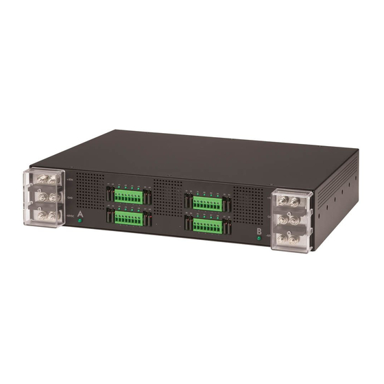
LED Indicators Outlets Units are equipped with a status LED for each power receptacle. A lit (on) LED indicates that power is being supplied at the port and a dim (off) LED indicates that there is no power at the port. Inlet Connections The PRO1 Sentry Switched DC PDU is equipped with two input blocks, each containing three clearly labeled terminal positions. -
Page 207: Appendix D: Led Indicators
Appendix D: LED Indicators The following input current LED indicators can be displayed on the Sentry DC PDU products: Behavior/Indicator Description Comments/User Action “--” (flashing double dashes) Occurs during normal boots, restarts, and firmware If the behavior is endless, contact Server flash updates but should revert to displaying Technology Technical Support at: amperage values upon completion. -
Page 208: Appendix E: Regulatory Compliance
Appendix E: Regulatory Compliance Product Safety Units have been safety tested and certified to the following standards: • USA/Canada UL 60950-1:2007 R10.14 and CAN/CSA 22.2 No. 60950-1-07 +A1+A2 • European Union EN 60950-1:2006 + A11 +A1 + A12 + A2 This product is also designed for Norwegian IT power system with phase-to phase voltage 230V. -
Page 209: Product Recycling
Japanese Notification この装置は、情報処理装置等電波障害自主規制協議会(VCCI)の基準に基づくクラス A 情報技 術装置です。この装置を家庭環境で使用すると電波妨害を引き起こすことがあります。この場合に は使用者が適切な対策を講ずるよう要求されることがあります。 本製品に同梱または付属しております電源コードは、本製品専用です。本製品以外の製品ならびに 他の用途に使用しないで下さい。 Chinese Notification 关于符合中国《电子信息产品污染控制管理办法》的声明 产品中有毒有害物质的名称及含量 有毒有害物质或元素 (Hazardous Substance) 部件名称 铅 (Pb) 汞 (Hg) 镉 (Cd) 六价铬 (Cr (VI)) 多溴联苯 (PBB) 多溴二苯醚 (PBDE) (Parts) 机箱子组件 (Chassis Subassembly) 印刷板组件 (PCAs) 表示该有毒有害物质在该部件所有均质材料中的含量均在 SJ/T 11363-2006 标准规定的限量要求以下。 Indicates that this hazardous substance contained in all homogeneous materials of this part is below the limit requirement in SJ/T 11363- 2006. -
Page 210: Appendix F: Product Support
Server Technology understands that there are often questions when installing and/or using a new product. Free Technical Support is provided from 8 a.m. to 5 p.m. Pacific Time, Monday through Friday. Server Technology, Inc. (a brand of Legrand) 1040 Sandhill Road... - Page 211 About Server Technology ® Server Technology, a brand of Legrand, is leading the engineering and manufacturing of customer-driven, innovative and exceptionally reliable power, access and control solutions for monitoring and managing critical IT assets for continual availability. Server Technology‘s power strategy experts are trusted to provide Rack PDU solutions for data centers worldwide ranging from small technology startups to Fortune 100 powerhouses.
Need help?
Do you have a question about the Server Technology PRO1 and is the answer not in the manual?
Questions and answers