
Related Manuals for Racal Instruments 2461


Summary of Contents for Racal Instruments 2461
- Page 1 (217) 352-9330 | Click HERE Find the Astronics / EADS / Racal 2461-Cd at our website:...
- Page 2 PUBLICATION DATE: November 19, 2004 Copyright 1998 by Racal Instruments, INC. Printed in the United States. All rights reserved. This book or parts thereof may not be reproduced in any form without written permission of the publisher. Artisan Technology Group - Quality Instrumentation ... Guaranteed | (888) 88-SOURCE | www.artisantg.com...
- Page 3 This warranty does not apply to defects resulting from any modification(s) of any product or part without Racal Instruments express written consent, or misuse of any product or part. The warranty also does not apply to fuses, software, non-rechargeable batteries, damage from battery leakage, or problems arising from normal wear, such as mechanical relay life, or failure to follow instructions.
- Page 4 Authorization is required from Racal Instruments before you send us your product for service or calibration. Call your nearest Racal Instruments support facility. A list is located on the last page of this manual. If you are unsure where to call, contact Racal Instruments, Inc. Customer Support Department in Irvine, California, USA at 1-800-722-3262 or 1-949-859-8999 or via fax at 1-949-859- 7139.
- Page 5 FOR YOUR SAFETY Before undertaking any troubleshooting, maintenance or exploratory procedure, read carefully the WARNINGS and CAUTION notices. This equipment contains voltage hazardous to human life and safety, and is capable of inflicting personal injury. If this instrument is to be powered from the AC line (mains) through an autotransformer, ensure the common connector is connected to the neutral (earth pole) of the power supply.
- Page 6 Artisan Technology Group - Quality Instrumentation ... Guaranteed | (888) 88-SOURCE | www.artisantg.com...
- Page 7 Artisan Technology Group - Quality Instrumentation ... Guaranteed | (888) 88-SOURCE | www.artisantg.com...
-
Page 8: Table Of Contents
2461Type C User Manual Table of Contents Chapter 1 ..........................1-1 GENERAL............................1-1 Introduction ............................ 1-1 Brief Description..........................1-2 Outstanding Resolution........................1-2 High Speed Time Measurement ....................1-2 Measurement Time Out ......................... 1-2 High Performance Trigger......................1-3 Voltage Measurements ........................1-3 Individual Channel Filtering...................... - Page 9 SENSE SUBSYSTEM........................4-51 SOURCE SUBSYSTEM ......................4-61 TEST SUBSYSTEM........................4-62 TRIGGER SUBSYSTEM ......................4-68 2461 TYPE C-Specific Error Messages..................4-75 Examples Of SCPI Commands Used To Manipulate The Instrument..........4-75 Selecting The Counter Function Card....................4-76 Preparation For Measurement .......................4-76 Triggering And Retrieving Measurements..................4-77 BASICS ..........................
- Page 10 Input 1 Attenuator Check ......................6-17 Input 2 Attenuator Check ......................6-18 Hysteresis Check for Input 1......................6-19 Hysteresis Check for Input 2......................6-19 Calibration, External Standard Output (2461-Ce and 2461-Cf) ...........6-20 Chapter 7 ..........................7-1 PRODUCT SUPPORT ........................7-1 Product Support ..........................
- Page 11 2461Type C User Manual List of Figures Figure 1-1, Universal Counter Timer 2461 Type C Function Card ..........1-1 Figure 1-2, High Speed Time Measurement..................1-2 Figure 1-3, High Performance Trigger ...................1-3 Figure 1-4, Selectable Sensitivity ....................1-4 Figure 1-5, Pulse Characterization ....................1-4 Figure 1-6, Powerful Arming Capability ..................1-5...
- Page 12 2461Type C User Manual Figure 6-11, External Standard Output ..................6-20 List of Tables Table 6-1, Input 1 Sensitivity Low Frequency Test ................6-2 Table 6-2, Input 1 Sensitivity high Frequency Performance Limits ..........6-3 Table 6-3, Input 2 Sensitivity Low Frequency Tests ..............6-5 Table 6-4, Input 2 Sensitivity High Frequency Tests ..............6-5 Table 6-5, Time Interval 1-2 Test Performance Limits ..............6-9 Artisan Technology Group - Quality Instrumentation ...
- Page 13 2461Type C User Manual This page was left intentionally blank. Artisan Technology Group - Quality Instrumentation ... Guaranteed | (888) 88-SOURCE | www.artisantg.com...
-
Page 14: Chapter 1
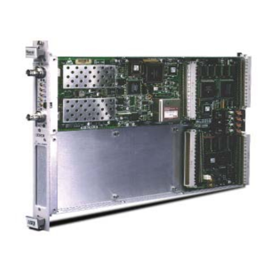
GENERAL The type C card is a high performance universal counter designed Introduction to be used with the innovative RACAL Instruments 2460 Series, VXI Modules. The Counter card offers eleven automatic measurement functions, including phase, pulse, peak, rise/fall time, time interval and ratio measurement, all with extremely high resolution. -
Page 15: Brief Description
2461Type C User Manual The 2461 Type C card is a member of the 2460 series instruments. Brief Description The 2461 Type C card is a high performance Universal Counter (UCT) offering eleven automatic measurement functions : • Frequency • Period •... -
Page 16: High Performance Trigger
This feature is used to measure Voltage Measurements High, Voltage Low and Average Voltage. Individual The 2461 Type C card offers independent 50 kHz low pass filters on each channel to allow measurements in noisy configurations. Channel Filtering Racal Instruments 1998 General 1-3 Artisan Technology Group - Quality Instrumentation ... -
Page 17: Selectable Sensitivity
Sensitivity is very important for system applications, requiring measurement of signals in noisy configurations. Figure 1-4, Selectable Sensitivity The 2461 Type C board provides automatic pulse characterization Pulse including Rise time, Fall time and pulse Width measurements. Characterization Figure 1-5, Pulse Characterization Phase measurements are performed automatically. -
Page 18: Powerful Arming Capability
2461Type C User Manual Powerful Arming The 2461 Type C card offers powerful arming capability. Different modes are provided with the ability to select the arming source Capability among the external arming input and the VXI TTLtrig lines. Figure 1-6, Powerful Arming Capability... -
Page 19: Measurement Principles
Once these are calibrated the value of the frequency of the input can be calculated to a much greater resolution. Racal Instruments 1998 General 1-6 Artisan Technology Group - Quality Instrumentation ... Guaranteed | (888) 88-SOURCE | www.artisantg.com... -
Page 20: Figure 1-7, Measurement Block
2461Type C User Manual Figure 1-7, Measurement Block Racal Instruments 1998 General 1-7 Artisan Technology Group - Quality Instrumentation ... Guaranteed | (888) 88-SOURCE | www.artisantg.com... - Page 21 2461Type C User Manual This page was left intentionally blank. Racal Instruments 1998 General 1-8 Artisan Technology Group - Quality Instrumentation ... Guaranteed | (888) 88-SOURCE | www.artisantg.com...
-
Page 22: Chapter 2
Failure to do so may cause damage to the unit. 1. Use the original packing material when returning the function Reshipment card to Racal Instruments for calibration or servicing. The Instructions original shipping carton and the instrument's plastic foam will provide the necessary support for safe reshipment. -
Page 23: Installation
(four on either side) on the sides of the cover. This will give access to the inside of the module. Racal Instruments 1998 Installation Instructions 2-2 Artisan Technology Group - Quality Instrumentation ... Guaranteed | (888) 88-SOURCE | www.artisantg.com... -
Page 24: Figure 2-2, Removing The Screws From The Module
Additionally, the front panel must be removed. There are eight screws that must be removed. Four for each of the small front panels. Figure 2-3, Removing the Front Panel Racal Instruments 1998 Installation Instructions 2-3 Artisan Technology Group - Quality Instrumentation ... Guaranteed | (888) 88-SOURCE | www.artisantg.com... -
Page 25: Figure 2-4, The 2461 Type C
1(see Figure 2-2). Secure it by screwing it down. There are four screws to install. Figure 2-4, The 2461 Type C 4 Screws Figure 2-5, Tightening the Four Screws. -
Page 26: Label Requirements
Requirements example) – will be the responsibility of the user. To update the configuration label on the 2461 the users should mark any changes in performance due to upgrades, e.g. peak and dynamic currents, etc. on the label found on the side panel on the module. - Page 27 2461Type C User Manual NOTE: Refer to Chapter 6 for the Performance Verification Procedure. Racal Instruments 1998 Installation Instructions 2-6 Artisan Technology Group - Quality Instrumentation ... Guaranteed | (888) 88-SOURCE | www.artisantg.com...
-
Page 28: Chapter 3
2461Type C User Manual Chapter 3 THEORY OF OPERATION The 2461 Type C card comprises 3 functional systems as Functional follows: Systems 1. The Input Channels 1 & 2 System 2. The Input Channel 3 System 3. The Measurement System 4. -
Page 29: Input Channel 3 System
The comparator output controls the low signal latch. If the detector output is below the Racal Instruments 1998 Theory Of Operation 3-2 Artisan Technology Group - Quality Instrumentation ... Guaranteed | (888) 88-SOURCE | www.artisantg.com... - Page 30 Channel 1 so that the two channels cannot be enabled at the same time. Racal Instruments 1998 Theory of Operation 3-3 Artisan Technology Group - Quality Instrumentation ... Guaranteed | (888) 88-SOURCE | www.artisantg.com...
-
Page 31: Figure 3-1, Inputs 1 &2
2461Type C User Manual Figure 3-1, Inputs 1 &2 Racal Instruments 1998 Theory Of Operation 3-4 Artisan Technology Group - Quality Instrumentation ... Guaranteed | (888) 88-SOURCE | www.artisantg.com... -
Page 32: Measurement System
The charge is then discharged at a much slower rate and while this is going on the reference is Racal Instruments 1998 Theory of Operation 3-5 Artisan Technology Group - Quality Instrumentation ... Guaranteed | (888) 88-SOURCE | www.artisantg.com... - Page 33 TEC circuits. Once these are calibrated the value of the frequency of the input can be calculated to a much greater resolution. Racal Instruments 1998 Theory Of Operation 3-6 Artisan Technology Group - Quality Instrumentation ... Guaranteed | (888) 88-SOURCE | www.artisantg.com...
-
Page 34: Figure 3-2, Measurement Block
2461Type C User Manual Figure 3-2, Measurement Block Racal Instruments 1998 Theory of Operation 3-7 Artisan Technology Group - Quality Instrumentation ... Guaranteed | (888) 88-SOURCE | www.artisantg.com... -
Page 35: Microprocessor System
VXI microcontroller as soon as it is calculated and before the next measurement cycle commences. Racal Instruments 1998 Theory Of Operation 3-8 Artisan Technology Group - Quality Instrumentation ... Guaranteed | (888) 88-SOURCE | www.artisantg.com... -
Page 36: Details Of The Counter
The 2461 Type C is designed to be controlled via the VXIbus. No local control of the counter is possible. The command set for the 2461 Type C is defined in Chapter 4 of this manual. Racal Instruments 1998 Theory of Operation 3-9 Artisan Technology Group - Quality Instrumentation ... -
Page 37: Measurement Functions
2461Type C User Manual The following measurement functions are available in the 2461 Measurement Type C: Functions Frequency Input 1 Measures the frequency of the signal applied to Input 1. Frequency Input 2 Measures the frequency of the signal applied to Input 2. - Page 38 Displays the sum total of events occurring at Input I between START and STOP events provided either by means of SCPI commands or a button on the soft front panel of the VXIplug&play install disk (Racal Instruments part number 60-0087). The summation of events is cumulative over successive...
- Page 39 Volts maximum Input 2 Measures the maximum (plus peak) voltage of the waveform at Input 2. Volts minimum Input 1 Racal Instruments 1998 Theory Of Operation 3-12 Artisan Technology Group - Quality Instrumentation ... Guaranteed | (888) 88-SOURCE | www.artisantg.com...
- Page 40 (i.e. the perceived DC level). During auto-triggering, the system will automatically select Racal Instruments 1998 Theory of Operation 3-13 Artisan Technology Group - Quality Instrumentation ... Guaranteed | (888) 88-SOURCE | www.artisantg.com...
-
Page 41: Signal Inputs
Input 3. Option 69 (package of replacement fuses) may be ordered as P/N R-11-1718. Additional ARMING Racal Instruments 1998 Theory Of Operation 3-14 Artisan Technology Group - Quality Instrumentation ... Guaranteed | (888) 88-SOURCE | www.artisantg.com... - Page 42 START and/or STOP circuits due to external noise (e.g. contact bounce). EXTERNAL FREQUENCY REFERENCE INPUT The 2461 Type C can make measurements using as its frequency reference an external signal connected to the front panel port marked STD IN.
- Page 43 INTERNAL FREQUENCY REFERENCE ADJUSTER The optional internal frequency reference oscillator can be adjusted by means of the front panel control marked OSC. Racal Instruments 1998 Theory Of Operation 3-16 Artisan Technology Group - Quality Instrumentation ... Guaranteed | (888) 88-SOURCE | www.artisantg.com...
-
Page 44: Chapter 4
Specific Commands Specific Error Messages Examples of Use The 2461 TYPE C Default Conditions form the default Default configuration that the 2461 TYPE C will adopt when the 2460 VXI Conditions Module is powered up. General default conditions COMMAND *RST OR SYSTEM:PRESET IEEE 488.2 COMMON COMMANDS... - Page 45 1M Ohm :ROUTe :FILTer [:LPASs] [:STATe] :COMParator :LEVel [:ABSolute] :HYSTeresis :RELative :SLOPe :SETup :AUTO :FREQuency 1000 Racal Instruments 1998 Programming The Type C Function Card 4-2 Artisan Technology Group - Quality Instrumentation ... Guaranteed | (888) 88-SOURCE | www.artisantg.com...
- Page 46 SYSTEM SUBSYSTEM SYSTem:TIMeout TEST SUBSYSTEM TEST[1 | 2] :RELay [:STATe] :TEC :SHORt [:STATe] :LONG [:STATe] :DAC [:STATe] Racal Instruments 1998 Programming The Type C Function Card 4-3 Artisan Technology Group - Quality Instrumentation ... Guaranteed | (888) 88-SOURCE | www.artisantg.com...
-
Page 47: Functional Check
:([SEQuence1] | STARt)[:LAYer] :SLOPe :SOURce :(SEQuence2 | STOP) :SLOPe :SOURce Functional Check The following procedure verifies that the 2461 TYPE C can accept, INTRODUCTION process, and transmit device- dependent messages over the VXIbus. Perform the following procedure: VXIBUS Communication Power-on the VXI Chassis/Mainframe containing the 2461... -
Page 48: List Of Scpi Commands
Negative pulse width measurement :TINTerval Time interval measurement :TOTalize Totalize measurement :PHASe Phase difference between waveforms :CHECk Functional tests Racal Instruments 1998 Programming The Type C Function Card 4-5 Artisan Technology Group - Quality Instrumentation ... Guaranteed | (888) 88-SOURCE | www.artisantg.com... - Page 49 Phase difference between waveforms measurement :CHECk Functional tests COMMAND DESCRIPTION READ? Initiates a measurement and returns the value. Racal Instruments 1998 Programming The Type C Function Card 4-6 Artisan Technology Group - Quality Instrumentation ... Guaranteed | (888) 88-SOURCE | www.artisantg.com...
- Page 50 OUTPut command summary COMMAND DESCRIPTION OUTPut :TTLTrg<n> Enables or disables the selected trigger line. [:STATe] Racal Instruments 1998 Programming The Type C Function Card 4-7 Artisan Technology Group - Quality Instrumentation ... Guaranteed | (888) 88-SOURCE | www.artisantg.com...
- Page 51 Enables on-the-fly Totalize measurements :INTermediate Starts and Stops Manual Totalize :MANual Specifies number of digits of resolution. :RESolution Racal Instruments 1998 Programming The Type C Function Card 4-8 Artisan Technology Group - Quality Instrumentation ... Guaranteed | (888) 88-SOURCE | www.artisantg.com...
- Page 52 2461Type C User Manual SOURce command summary COMMAND DESCRIPTION SOURce :ROSCillator [:SOURce] Selects the source of the 2461 TYPE C 10 MHz reference oscillator. TEST command summary COMMAND DESCRIPTION TEST[1 | 2] :RELay [:STATe] Test 2461 TYPE C relays. :TEC :SHORt [:STATe] Test short period TEC.
-
Page 53: 2461 Type C Commands
The CALCulate subsystem is used to perform post-acquisition CALCULATE data processing. Subsystem In the following sections of the manual references are made to channels 1 and 2. These refer to the 2461 TYPE C Input 1 and Input 2. CALCulate command summary COMMAND DESCRIPTION... - Page 54 *RST value1 = 0 (offset) value2 = 1 (scale) EXAMPLE: ″CALCulate:MATH:EXPRession 1000,MEASure″ Specifies an offset of 1000 and instructs the 2461 TYPE C to use the previous measurement as a scale factor. INTERROGATIVE FORM: CALCulate:MATH:EXPRession? ==> <offset value, scale value>...
-
Page 55: Measurement Subsystem
INPut subsystem. The reconfiguration of the measurement function invalidates the previously acquired data. If the CONFigure command is sent while the 2461 TYPE C is initiated, then the measurement in progress is aborted before the reconfiguration takes place. - Page 56 [,<expected value>, <resolution>] DESCRIPTION: These commands configure the 2461 TYPE C to measure the trigger level voltage on the selected channel. The 2461 TYPE C can be configured to measure the maximum, minimum and mid-point trigger level voltages. Racal Instruments 1998 Programming The Type C Function Card 4-13 Artisan Technology Group - Quality Instrumentation ...
- Page 57 Their units are volts. INITIALIZATION: *RST Resolution = 8 Array size = 1 EXAMPLE: ″CONFigure1:VOLTage:MAXimum″ Configures the 2461 TYPE C to measure the maximum (positive peak) trigger level on channel 1 (single measurement). NO INTERROGATIVE FORM ******************************************************* CONFigure[1 | 2 ][:SCALar]:FREQuency [<expected value>, <resolution>]...
- Page 58 The optional <expected value> and <resolution> parameters are used to derive the required number of digits of resolution. Their have no units. The actual resolution derived by the 2461 TYPE C is determined by both the input signal and the resolution set. INITIALIZATION:...
- Page 59 FTIMe and RTIMe are aliases for the FALL:TIME and RISe:TIME commands respectively. These commands configure the 2461 TYPE C to measure the fall time and rise time of the signal. The fall time is the period the signal takes to go from 90% to 10% of its peak value. The rise time is the period the signal takes to go from 10% to 90% of its peak value.
- Page 60 2461Type C User Manual EXAMPLE: ″CONFigure1:FALL:TIME″ Configures the 2461 TYPE C to measure the fall time of the sig applied to channel 1. NO INTERROGATIVE FORM ******************************************************* CONFigure[1 | 2][:SCALAR]:PERiod [<EXPECTED VALUE>, <RESOLUTION>] CONFigure[1 | 2]:ARRay:PERiod <ARRAY SIZE>[,<EXPECTED VALUE>, <RESOLUTION>]...
- Page 61 The optional <expected value> and <resolution> parameters are used to derive the required number of digits of resolution. Their units are seconds. The actual resolution derived by the 2461 TYPE C is determined by both the input signal and the resolution set. INITIALIZATION:...
- Page 62 The optional <expected value> and <resolution> parameters are used to derive the required number of digits of resolution. Their units are seconds. The actual resolution derived by the 2461 TYPE C is determined by both the input signal and the resolution set. INITIALIZATION:...
- Page 63 CONFigure[1 | 2]:ARRay:TOTalize <array size>[<expected value>, <resolution>] DESCRIPTION: These commands configure the 2461 TYPE C to totalize events occurring at channels 1 or 2. The counting interval can be controlled by: (1) Electrical start and stop signals applied to the channel 2 input (Totalize 1 by 2) or to the channel 1 input (Totalize 2 by (2) Successive operations (Manual Totalize).
- Page 64 2461Type C User Manual ″CONFigure1:TOTalize″ Configures the 2461 TYPE C to totalize events occurring at channel 1 input during the time window defined by signal on channel 2. NO INTERROGATIVE FORM ******************************************************* CONFigure[1 | 2][:SCALar]:PHASe [<expected value>, <resolution>] CONFigure[1 | 2]:ARRay:PHASe <array size> [,<expected value>, <resolution>]...
- Page 65 Their units are Hertz. INITIALIZATION: *RST Resolution = 8 Array size = 1 EXAMPLE: ″CONFigure:CHECk″ Configures the 2461 TYPE C to measure the frequency standard. NO INTERROGATIVE FORM ************************************************* Racal Instruments 1998 Programming The Type C Function Card 4-22...
- Page 66 FREQuency, the current channel is 1 and an ARRay-type measurement (5 samples) was specified. Initialization: *RST FREQ1,1 Racal Instruments 1998 Programming The Type C Function Card 4-23 Artisan Technology Group - Quality Instrumentation ... Guaranteed | (888) 88-SOURCE | www.artisantg.com...
-
Page 67: Fetch Subsystem
If a measurement or an array of measurements has not been completed, the 2461 TYPE C will delay the read until the measurement(s) have completed. The default value of <count> is the number of measurements specified by the last CONFigure or MEASure? commands. - Page 68 +00005.0000000E+06. The number of returned bytes in the VXI output buffer is fixed at 18 bytes. Initialization: Not Applicable Racal Instruments 1998 Programming The Type C Function Card 4-25 Artisan Technology Group - Quality Instrumentation ... Guaranteed | (888) 88-SOURCE | www.artisantg.com...
- Page 69 <start>, then all <step> values after start are returned. Racal Instruments 1998 Programming The Type C Function Card 4-26 Artisan Technology Group - Quality Instrumentation ... Guaranteed | (888) 88-SOURCE | www.artisantg.com...
-
Page 70: Measure Subsystem
<array size> parameter. The limit for this parameter is 16384. If the MEASure command is sent while the 2461 TYPE C is initiated, then measurement in progress is aborted before the reconfiguration takes place. - Page 71 MEASure[1 | 2]:ARRay:VOLTage:MIDDle? <array size> [,<expected value>, <resolution>] DESCRIPTION: These commands set the 2461 TYPE C to measure the trigger level voltage on the selected channel. The 2461 TYPE C can be instructed to measure the maximum, minimum and mid-point trigger level voltages.
- Page 72 MEASure[1 | 2 | 3]:ARRay:FREQuency? <array size> [,<expected value>, <resolution>] DESCRIPTION: These commands set the 2461 TYPE C to measure the frequency of the signal on the input channel specified. The ARRay command programs the counter for multiple frequency measurements as specified by the <array size>...
- Page 73 The optional <expected value> and <resolution> parameters are used to derive the required number of digits of resolution. They have no units. The actual resolution derived by the 2461 TYPE C is determined by both the input signal and the resolution set. INITIALIZATION:...
- Page 74 FTIMe and RTIMe are an alias for the FALL:TIME and RISe:TIME commands respectively. These commands set the 2461 TYPE C to measure the fall time and rise time of the signal. The fall time is the period the signal takes to go from 90% to 10% of its peak value.
- Page 75 Their units are seconds. INITIALIZATION: *RST Resolution = 8 Array size = 1 EXAMPLE: ″MEASure1:Period? ″ Instructs the 2461 TYPE C to measure the period of the signal applied to channel 1. ******************************************************* MEASure[1][:SCALar]:PWIDth? [<expected value>, <resolution>] MEASure[1]:ARRay:PWIDth?<array size> [,<expected value>, <resolution>] MEASure[1][:SCALar]:NWIDth? [<expected value>, <resolution>]...
- Page 76 The optional <expected value> and <resolution> parameters are used to derive the required number of digits of resolution. Their units are seconds. The actual resolution derived by the 2461 TYPE C is determined by both the input signal and the resolution set. INITIALIZATION:...
- Page 77 The optional <expected value> and <resolution> parameters are used to derive the required number of digits of resolution. Their units are seconds. The actual resolution derived by the 2461 TYPE C is determined by both the input signal and the resolution set. INITIALIZATION:...
- Page 78 *RST Resolution = 8 Array size = 1 EXAMPLE: ″MEASure1:TOTalize? ″ Instructs the 2461 TYPE C to totalize events occurring at channel 1 input during the time window defined by signal on channel 2. ******************************************************* MEASure[1 | 2][:SCALar]:PHASe? [<expected value>, <resolution>]...
- Page 79 2461Type C User Manual EXAMPLE: ″MEASure2:PHASe? 100″ Instructs the 2461 TYPE C to measure the phase difference between the waveform applied to the channel 2 input and that applied to channel 1 input. ******************************************************* MEASure:CHECk? [<expected value>, <resolution>] DESCRIPTION: This command connects the standard frequency in use to the counting input and takes frequency measurements.
- Page 80 Initiates a new measurement cycle on the currently selected function. The <expected value> and <resolution> parameters specify 6 digits of resolution. Racal Instruments 1998 Programming The Type C Function Card 4-37 Artisan Technology Group - Quality Instrumentation ... Guaranteed | (888) 88-SOURCE | www.artisantg.com...
-
Page 81: Read Subsystem
(refer to SYSTem:TIMeout) may have to be increased. Initialization: Not Applicable Example: READ? Initiates and retrieves a measurement on the selected function Racal Instruments 1998 Programming The Type C Function Card 4-38 Artisan Technology Group - Quality Instrumentation ... Guaranteed | (888) 88-SOURCE | www.artisantg.com... -
Page 82: Input Subsystem
2461Type C User Manual The INPut subsystem has the function of specifying some of the INPut Subsystem characteristics of the 2461 TYPE C, such as attenuation, coupling, impedance, etc. The query form of these commands returns the setting previously specified. - Page 83 INPut[1 | 2]:COUPling <AC | DC | DEFault> DESCRIPTION: Selects the input coupling for the specified channel. PARAMETERS: DEFault = AC INITIALIZATION: Racal Instruments 1998 Programming The Type C Function Card 4-40 Artisan Technology Group - Quality Instrumentation ... Guaranteed | (888) 88-SOURCE | www.artisantg.com...
- Page 84 Returns the current impedance setting for the specified channel. ******************************************************* INPut[1 | 2]:ROUTe <SEParate | COMMon | DEFault> DESCRIPTION: Racal Instruments 1998 Programming The Type C Function Card 4-41 Artisan Technology Group - Quality Instrumentation ... Guaranteed | (888) 88-SOURCE | www.artisantg.com...
- Page 85 Selects the input block signal low-pass filter state for the specified channel to ON or OFF. PARAMETERS: DEFault = OFF Racal Instruments 1998 Programming The Type C Function Card 4-42 Artisan Technology Group - Quality Instrumentation ... Guaranteed | (888) 88-SOURCE | www.artisantg.com...
- Page 86 VOLT:MIN and VOLT:MIDD are active and the channel specified is the same as the channel currently configured for Racal Instruments 1998 Programming The Type C Function Card 4-43 Artisan Technology Group - Quality Instrumentation ... Guaranteed | (888) 88-SOURCE | www.artisantg.com...
- Page 87 PERiod, TINTerval, TOTalize, FREQuency:RATio and CHECk are active, then, in addition to the setting of the Racal Instruments 1998 Programming The Type C Function Card 4-44 Artisan Technology Group - Quality Instrumentation ... Guaranteed | (888) 88-SOURCE | www.artisantg.com...
- Page 88 Note that the attenuation setting is ignored. INPut[1 | 2]:COMParator:HYSTeresis:RELative <MINimum | MAXimum | DEFault> Racal Instruments 1998 Programming The Type C Function Card 4-45 Artisan Technology Group - Quality Instrumentation ... Guaranteed | (888) 88-SOURCE | www.artisantg.com...
- Page 89 If NEGative is specified while the function PWIDth is active and channel 1 is specified, then the error –240 is generated (“Function Error”). Racal Instruments 1998 Programming The Type C Function Card 4-46 Artisan Technology Group - Quality Instrumentation ... Guaranteed | (888) 88-SOURCE | www.artisantg.com...
- Page 90 –240 is generated (“Function Error”). PARAMETERS: DEFault = OFF Racal Instruments 1998 Programming The Type C Function Card 4-47 Artisan Technology Group - Quality Instrumentation ... Guaranteed | (888) 88-SOURCE | www.artisantg.com...
- Page 91 MIN = 50Hz MAX = 1000Hz INITIALIZATION: *RST 1000Hz INTERROGATIVE FORM INPut[1 | 2]:COMParator:SETup:AUTO:FREQuency? ==> <MINimum|MAXimum> Racal Instruments 1998 Programming The Type C Function Card 4-48 Artisan Technology Group - Quality Instrumentation ... Guaranteed | (888) 88-SOURCE | www.artisantg.com...
- Page 92 2461Type C User Manual Returns the current minimum frequency setting for the auto trigger. Racal Instruments 1998 Programming The Type C Function Card 4-49 Artisan Technology Group - Quality Instrumentation ... Guaranteed | (888) 88-SOURCE | www.artisantg.com...
-
Page 93: Output Subsystem
If the TTLTrg line specified is already being used for the start or stop arming by one of the 2461 TYPE C boards in the system (refer to the TRIGger subsystem), then the error –221 is generated (“Setting conflict”). -
Page 94: Sense Subsystem
The reconfiguration of the measurement function invalidates the previously acquired data. If the SENSe:FUNCtion command is sent while the 2461 TYPE C is initiated, then measurement in progress is aborted before the reconfiguration takes place SENSe command summary... - Page 95 The possible strings are: ″FREQ″ ″FREQ:RAT″ ″VOLT:MAX″ ″VOLT:MIN″ ″VOLT:MIDD″ ″PWID″ ″NWID″ ″PER″ ″RTIM″ ″FTIM″ Racal Instruments 1998 Programming The Type C Function Card 4-52 Artisan Technology Group - Quality Instrumentation ... Guaranteed | (888) 88-SOURCE | www.artisantg.com...
- Page 96 MINimum | MAXimum | DEFault | <value> Description: These commands all do the same thing. They set the 2461 TYPE C measurement aperture <time>. The units are seconds and range from 1E-6 to 10. If the user specifies a value, then this will be rounded up or down to the nearest of 1µs, 10µs,...
- Page 97 <ON | OFF> Description: Enables or disables the averaging of measurement results. When the average function is enabled, the 2461 TYPE C takes 100 measurements and derives the average value. Note that the resolution increases by one digit when this function is enabled.
- Page 98 Selects maximum time delay interval. Interrogative form: [SENSe]:TINTerval:DELay:TIME? ==> <time delay interval> Returns the time delay selected. ******************************************************************** Racal Instruments 1998 Programming The Type C Function Card 4-55 Artisan Technology Group - Quality Instrumentation ... Guaranteed | (888) 88-SOURCE | www.artisantg.com...
- Page 99 Initialization: *RST ON Example: “CONF2:TOT” ″SENSe:TOTalize:GATE ON″ Selects the Totalize 2 by 1 measurement function.. Racal Instruments 1998 Programming The Type C Function Card 4-56 Artisan Technology Group - Quality Instrumentation ... Guaranteed | (888) 88-SOURCE | www.artisantg.com...
- Page 100 If this feature is enabled, FETCh? queries sent during the totalize measurement will return the last intermediate result. Racal Instruments 1998 Programming The Type C Function Card 4-57 Artisan Technology Group - Quality Instrumentation ... Guaranteed | (888) 88-SOURCE | www.artisantg.com...
- Page 101 *RST Example: CONFigure2:TOTalize Selects TOTalize function; SENSe:TOTalize:GATE OFF Enables Manual Totalize; SENSe2:TOTalize:MANual ON Starts the counting Racal Instruments 1998 Programming The Type C Function Card 4-58 Artisan Technology Group - Quality Instrumentation ... Guaranteed | (888) 88-SOURCE | www.artisantg.com...
- Page 102 *RST Parameters: 3 ≤ value ≤ 10 MIN = 3 MAX = 10 DEF = 8 Racal Instruments 1998 Programming The Type C Function Card 4-59 Artisan Technology Group - Quality Instrumentation ... Guaranteed | (888) 88-SOURCE | www.artisantg.com...
- Page 103 Selects 6 as the number of digits of resolution. Interrogative form: SENSe:RESolution? <Number of digits> Returns the current number of digits of resolution. Racal Instruments 1998 Programming The Type C Function Card 4-60 Artisan Technology Group - Quality Instrumentation ... Guaranteed | (888) 88-SOURCE | www.artisantg.com...
-
Page 104: Source Subsystem
<CLOCk10 | INTernal | EXTernal | DEFault> Description: This command selects the source of the 2461 TYPE C 10 MHz reference oscillator. Valid sources are the on-board 10 MHz reference (INTernal), the VXIbus backplane 10 MHz signal (CLOCk10), and an external source (EXTernal). -
Page 105: Test Subsystem
2461Type C User Manual TEST command summary TEST SUBSYSTEM COMMAND DESCRIPTION TEST[1 | 2] :RELay Test 2461 TYPE C relays. :TEC :SHORt [:STATe] Test short period TEC. :LONG [:STATe] Test long period TEC. :DAC [:STATe] Test ramp trigger DACs TEST[1 | 2]:RELay <OFF | ON>... - Page 106 Note that this test can only be performed when the CHECk function is selected. On reception of this command, the 2461 TYPE C checks the operation of the TEC circuit continuously until the state is turned off, another state is turned on, or the CHECk function is de- selected.
- Page 107 Note that this test can only be performed when the CHECk function is selected. On reception of this command, the 2461 TYPE C checks the operation of the TEC circuit continuously until the state is turned off, another state is turned on, or the CHECk function is de- selected.
- Page 108 Note that this test can only be performed when the CHECk function is selected. On reception of this command, the 2461 TYPE C checks the operation of the TEC circuit continuously until the state is turned off, another state is turned on, or the CHECk function is de- selected.
- Page 109 Note that this test can only be performed when the CHECk function is selected. On reception of this command, the 2461 TYPE C checks the operation of the TEC circuit continuously until the state is turned off, another state is turned on, or the CHECk function is de- selected.
- Page 110 Since this test checks both DACs, the channel number is irrelevant. On reception of this command, the 2461 TYPE C checks the operation of the DACs continuously until the state is turned off, another state is turned on, or the CHECk function is de- selected.
-
Page 111: Trigger Subsystem
TRIGGER configure the arming layer of the trigger model. SUBSYSTEM The trigger model for the 2461 TYPE C is based on the expanded capability Trigger Model with subservient sequences defined in the SCPI Command reference. Changing any of the ARMing settings invalidates the previously acquired data. - Page 112 If INIT:CONT ON is not received then SEQUENCE1 moves up to the IDLE layer and waits for the next command. Racal Instruments 1998 Programming The Type C Function Card 4-69 Artisan Technology Group - Quality Instrumentation ... Guaranteed | (888) 88-SOURCE | www.artisantg.com...
- Page 113 2461Type C User Manual TRIGger command summary COMMAND DESCRIPTION INITiate Enter in the INITiate state. :IMMediate Causes the 2461 TYPE C to operate in :CONTinous continuous mode [:STATe] ABORt Aborts and operation in progress ARMing ([:SEQuence1] | :STARt)[:LAYer] Slope of the arming signal for start.
- Page 114 INITiate command will cause the instrument to re-start the same type of measurement. Racal Instruments 1998 Programming The Type C Function Card 4-71 Artisan Technology Group - Quality Instrumentation ... Guaranteed | (888) 88-SOURCE | www.artisantg.com...
- Page 115 Returns the slope of the start arming signal. ************************************************************* ARMing([:SEQuence1] | :STARt)[:LAYer]:SOURce <CTR_EXTARM | TTLTrg<0..7> |IMMediate > Racal Instruments 1998 Programming The Type C Function Card 4-72 Artisan Technology Group - Quality Instrumentation ... Guaranteed | (888) 88-SOURCE | www.artisantg.com...
- Page 116 CTR_EXTARM, this will be forced to TTLTrg. If the TTLTrg line specified is already being used for the gate output signal of one of the 2461 TYPE C boards in the system (refer to the OUTPut subsystem), then the error –221 is generated (“Setting conflict”).
- Page 117 CTR_EXTARM, this will be forced to TTLTrg. If the TTLTrg line specified is already being used for the gate output signal of one of the 2461 TYPE C boards in the system (refer to the OUTPut subsystem), then the error –221 is generated (“Setting conflict”).
-
Page 118: 2461 Type C-Specific Error Messages
Interrogative form: ARMing: (SEQuence2 | STOP)[:LAYer]:SOURce? ==> <CTR_EXTARM | TTLTrg<0..7> | IMMediate> Returns the source of the stop arming signal. 2461 TYPE C- Error Description [Description/Explanation/Examples] Specific Error Number Messages -311 Memory-related error [An error has occurred in one of the memory areas of the module. -
Page 119: Selecting The Counter Function Card
2461. Note that if the second field is present but a null value then the lower position is unoccupied. - Page 120 The SCPI standard provides 3 commands for retrieving and/or Triggering And taking measurements and two commands for triggering Retrieving measurements. Racal Instruments 1998 Programming The Type C Function Card 4-77 Artisan Technology Group - Quality Instrumentation ... Guaranteed | (888) 88-SOURCE | www.artisantg.com...
-
Page 121: Basics
MULTIPLE MEASUREMENTS It is possible to command the 2461 TYPE C to take multiple, or array, type measurements using the CONFigure subsystem. The CONF command is used standalone or with the MEAS? Command. -
Page 122: Automatic Resolution
1 will be taken and the results placed in the output queue. AUTOMATIC RESOLUTION It is possible to have the 2461 TYPE C function card set the resolution automatically if the expected value and measurement resolution are supplied. This is done using the CONF command. - Page 123 2461Type C User Manual This page was left intentionally blank. Racal Instruments 1998 Programming The Type C Function Card 4-80 Artisan Technology Group - Quality Instrumentation ... Guaranteed | (888) 88-SOURCE | www.artisantg.com...
-
Page 124: Chapter 5
‘YES’ option. If one or more 2461 are found then the main front panel of the 2461 will appear on the screen and the operator should select the Universal Counter Timer. The main 2461 UCT panel will... -
Page 125: Figure 5-1, 2461-C Front Panel
2461Type C User Manual Figure 5-1, 2461-C Front Panel The controls are: The Function list box allows the user to select the 2461 TYPE C measurement function. The functions available are: "Frequency Input 1" "Frequency Input 2" "Frequency Input 3"... - Page 126 The Single Shot and Continuous buttons control the actual measurement process. Pressing the Single Shot button initiates a 2461 Type C measurement and acquires the result. Pressing the Continuous button causes the 2461 Type C to take continuous measurements with the results reported in real-time.
- Page 127 Offset values. The About button, shown in figure 5-6, contains information on the instrument Install Disk. The Display 2461 button re-enables the main Soft Front Panel of the 2461 application. The Hide button temporarily disables the panel 2461 Type C panel.
-
Page 128: Arm Source Configuration
“Front Panel” The Gate Output Destination control has the following entries: “ TTLTRG0” “TTLTRG1” “TTLTRG2” “TTLTRG3” Racal Instruments 1998 Using The VXI plug&play Install Disks 5-5 Artisan Technology Group - Quality Instrumentation ... Guaranteed | (888) 88-SOURCE | www.artisantg.com... -
Page 129: Configure Inputs
2461Type C User Manual “TTLTRG4” “TTLTRG5” “TTLTRG6” “TTLTRG7” “Off” For each 2461 Type C function card, the following parameters Configure Inputs can be set: Figure 5-3, Configure Input secondary panel • The Coupling control sets the input coupling (AC or DC). - Page 130 Apply is subsequently operated. The Cancel button closes the soft front panel ignoring any change made to the settings. Racal Instruments 1998 Using The VXI plug&play Install Disks 5-7 Artisan Technology Group - Quality Instrumentation ... Guaranteed | (888) 88-SOURCE | www.artisantg.com...
-
Page 131: Select Reference
The Cancel button closes the panel leaving the frequency standard setting unchanged. Figure 5-4, Select Reference Racal Instruments 1998 Using The VXI plug&play Install Disks 5-8 Artisan Technology Group - Quality Instrumentation ... Guaranteed | (888) 88-SOURCE | www.artisantg.com... -
Page 132: Configure Math Function
The Cancel button closes the soft front panel ignoring any change made to the settings. Figure 5-5, Configure Math Function secondary panel Racal Instruments 1998 Using The VXI plug&play Install Disks 5-9 Artisan Technology Group - Quality Instrumentation ... Guaranteed | (888) 88-SOURCE | www.artisantg.com... -
Page 133: About
SCPI version, firmware revision and the module serial number. Figure 5-6, About secondary panel Racal Instruments 1998 Using The VXI plug&play Install Disks 5-10 Artisan Technology Group - Quality Instrumentation ... Guaranteed | (888) 88-SOURCE | www.artisantg.com... -
Page 134: Chapter 6
RF Millivoltmeter, as appropriate, and adjusted to give a level as close to its nominal value as can be achieved before being applied to the UCT. Racal Instruments 1998 Performance Verification and Adjustments 6-1 Artisan Technology Group - Quality Instrumentation ... Guaranteed | (888) 88-SOURCE | www.artisantg.com... -
Page 135: Input 1 Sensitivity Test
25mV). Command Syntax: MEAS1:FREQ? takes a frequency measurement Table 6-1, Input 1 Sensitivity Low Frequency Test Racal Instruments 1998 Performance Verification and Adjustments 6-2 Artisan Technology Group - Quality Instrumentation ... Guaranteed | (888) 88-SOURCE | www.artisantg.com... -
Page 136: Table 6-2, Input 1 Sensitivity High Frequency Performance Limits
10MHz 25mV rms SENS:RES 8 ± 1Hz 100kHz 25mV rms SENS:RES 8 ± 0.1Hz Disconnect the test equipment. Racal Instruments 1998 Performance Verification and Adjustments 6-3 Artisan Technology Group - Quality Instrumentation ... Guaranteed | (888) 88-SOURCE | www.artisantg.com... -
Page 137: Input 2 Sensitivity Test
Check the UCT gives a stable reading within the tolerances given, at less than the signal levels given. Command Syntax: MEAS1:FREQ? takes a frequency measurement Racal Instruments 1998 Performance Verification and Adjustments 6-4 Artisan Technology Group - Quality Instrumentation ... Guaranteed | (888) 88-SOURCE | www.artisantg.com... -
Page 138: Table 6-3, Input 2 Sensitivity Low Frequency Tests
10MHz 25mV rms SENS:RES 8 ± 1Hz 100kHz 25mV rms SENS:RES 8 ± 0.1Hz Disconnect the test equipment. Racal Instruments 1998 Performance Verification and Adjustments 6-5 Artisan Technology Group - Quality Instrumentation ... Guaranteed | (888) 88-SOURCE | www.artisantg.com... - Page 139 NOT, therefore, be run with a 2461 that is not fitted with this hardware.) 6. If there is more than one 2461 in system select the required 2461, otherwise selection is automatic. 7. If the 9087 is connected via the GPIB then it will be controlled automatically, otherwise set the signal generator output to 1GHz at 10.0mV rms (i.e.
- Page 140 2461Type C User Manual instructions as presented by the program.) 11. Verify that the 2461 is not counting. If it is, repeat steps 7 to 12, (i.e. follow the instructions as presented by the program.) 12. When satisfied that the setup is complete press “Stop”...
-
Page 141: Time Interval 1:2 Test
Set the UCT input trigger slopes as shown in the following table and check that the UCT measurement results are as given in Table 6-5. Racal Instruments 1998 Performance Verification and Adjustments 6-8 Artisan Technology Group - Quality Instrumentation ... Guaranteed | (888) 88-SOURCE | www.artisantg.com... -
Page 142: Table 6-5, Time Interval 1-2 Test Performance Limits
± 2ns INP1:COMP:SLOP POS INP2:COMP:SLOP NEG Command Syntax: MEAS:TINT? takes a Time Interval measurement Disconnect the test equipment. Racal Instruments 1998 Performance Verification and Adjustments 6-9 Artisan Technology Group - Quality Instrumentation ... Guaranteed | (888) 88-SOURCE | www.artisantg.com... -
Page 143: Totalize 1 By 2 Test
Command Syntax for making a Totalize measurement: CONF1:TOT configures UCT for Totalize measurement MEAS1:TOT? takes a totalize measurement Racal Instruments 1998 Performance Verification and Adjustments 6-10 Artisan Technology Group - Quality Instrumentation ... Guaranteed | (888) 88-SOURCE | www.artisantg.com... -
Page 144: Ratio 1:2 Test
Figure 6-5, Ratio 1 : 2 Test Configuration Command Syntax: MEAS1:FREQ:RAT? measures the ratio of frequencies at Inputs 1 & 2 Disconnect the test equipment. Racal Instruments 1998 Performance Verification and Adjustments 6-11 Artisan Technology Group - Quality Instrumentation ... Guaranteed | (888) 88-SOURCE | www.artisantg.com... -
Page 145: Trigger Level Accuracy Test
Reverse the polarity of the DC input to UCT. Verify that the trigger level is –4.000V +/- 290mV. Command Syntax: Racal Instruments 1998 Performance Verification and Adjustments 6-12 Artisan Technology Group - Quality Instrumentation ... Guaranteed | (888) 88-SOURCE | www.artisantg.com... - Page 146 290 mV MEAS2:VOLT:MAX? -4.000 V MEAS2:VOLT:MIN? 290 mV +8.000 V MEAS2:VOLT:MAX? 1.3 V -8.000 V MEAS2:VOLT:MIN? 1.3 V Racal Instruments 1998 Performance Verification and Adjustments 6-13 Artisan Technology Group - Quality Instrumentation ... Guaranteed | (888) 88-SOURCE | www.artisantg.com...
-
Page 147: Functional Checks
2dB. INP1:FILT:LPAS:STAT ON turn on LPF for channel 1 MEAS1:FREQ? Confirm 50kHz MEAS1:VOLT:MAX? MEAS1:VOLT:MIN? Racal Instruments 1998 Performance Verification and Adjustments 6-14 Artisan Technology Group - Quality Instrumentation ... Guaranteed | (888) 88-SOURCE | www.artisantg.com... -
Page 148: Input 2 Filter Check
50kHz. Measure the peak to peak signal and verify that the signal amplitude is reduced by greater than 2dB. Racal Instruments 1998 Performance Verification and Adjustments 6-15 Artisan Technology Group - Quality Instrumentation ... Guaranteed | (888) 88-SOURCE | www.artisantg.com... - Page 149 MEAS2:FREQ? Confirm 50kHz MEAS2:VOLT:MAX? MEAS2:VOLT:MIN? Use the equation : − − > − − > to verify compliance. Racal Instruments 1998 Performance Verification and Adjustments 6-16 Artisan Technology Group - Quality Instrumentation ... Guaranteed | (888) 88-SOURCE | www.artisantg.com...
-
Page 150: Input 1 Attenuator Check
Note.the signal generator output level and check that this level is approximately ten times the level previously noted. Disconnect the test equipment. Racal Instruments 1998 Performance Verification and Adjustments 6-17 Artisan Technology Group - Quality Instrumentation ... Guaranteed | (888) 88-SOURCE | www.artisantg.com... -
Page 151: Input 2 Attenuator Check
Note the signal generator output level and check that this level is approximately ten times the level previously noted. Disconnect the test equipment. Racal Instruments 1998 Performance Verification and Adjustments 6-18 Artisan Technology Group - Quality Instrumentation ... Guaranteed | (888) 88-SOURCE | www.artisantg.com... -
Page 152: Hysteresis Check For Input 1
30mV and verify the UCT has a stable reading. Command syntax: INP2:COMP:HYST:REL MAX enables hysteresis MEAS2:FREQ? takes a measurement Disconnect the test equipment. Racal Instruments 1998 Performance Verification and Adjustments 6-19 Artisan Technology Group - Quality Instrumentation ... Guaranteed | (888) 88-SOURCE | www.artisantg.com... -
Page 153: Calibration, External Standard Output (2461-Ce And 2461-Cf)
2461Type C User Manual Internal Frequency Standard Adjustment Calibration, External Standard Prior to calibration, the 2461-Ce or -Cf must be in continuous operation for 4 hours at an ambient Output (2461-Ce temperature of 23 +/-2°C. and 2461-Cf Connect the master frequency standard (9480/FRS or equivalent) to INPUT 1 of the 2461-Ce or -Cf Frequency Counter. - Page 154 Allow the reading to stabilize for 5 minutes and re- adjust to the following tolerances: TCXO: 1 Hz OCXO: 0.1 Hz Racal Instruments 1998 Performance Verification and Adjustments 6-21 Artisan Technology Group - Quality Instrumentation ... Guaranteed | (888) 88-SOURCE | www.artisantg.com...
- Page 155 2461Type C User Manual This page was left intentionally blank. Racal Instruments 1998 Performance Verification and Adjustments 6-22 Artisan Technology Group - Quality Instrumentation ... Guaranteed | (888) 88-SOURCE | www.artisantg.com...
-
Page 156: Chapter 7
2461Type C User Manual Chapter 7 PRODUCT SUPPORT Racal Instruments has a complete Service and Parts Department. Product Support If you need technical assistance or should it be necessary to return your product for repair or calibration, call 1-800-722-3262. If parts are required to repair the product at your facility, call 1-949-859-8999 and ask for the Parts Department. - Page 157 Tel: +39 (0)2 6123 901; Fax: +39 (0)2 6129 3606 Technologie Park, Friedrich Ebert Strasse, 51429 Bergisch Gladbach, Germany Tel: +49 (0) 2204 844200; Fax: +49 (0) 2204 844219 Racal Instruments 1998 Product Support 7-2 Artisan Technology Group - Quality Instrumentation ... Guaranteed | (888) 88-SOURCE | www.artisantg.com...
- Page 158 (please circle one) Call before shipping Ship instruments to nearest support office Note: We do not accept Iisted on back. “collect” shipments. Racal Instruments 1998 Product Support 7-3 Artisan Technology Group - Quality Instrumentation ... Guaranteed | (888) 88-SOURCE | www.artisantg.com...
- Page 159 2461Type C User Manual This page was left intentionally blank. Racal Instruments 1998 Product Support 7-4 Artisan Technology Group - Quality Instrumentation ... Guaranteed | (888) 88-SOURCE | www.artisantg.com...
-
Page 160: Appendix A: Specifications
User Manual 2461 Type C Appendix A Model 2461 Type C SPECIFICATIONS WARNING To ensure protection against electrical shock, the warnings detailed in the Safety Precautions page of the handbook must be observed. Technical Specification Channels 1 and 2 - Input Characteristics Channels 1 and 2 are coupled via INPUT 1 and INPUT 2 respectively. - Page 161 User Manual 2461 Type C 1MΩ nominal shunted by ≤ 55pF INPUT 1 in COMMON mode: 50Ω (DC coupled) Sensitivity ×1 attenuation Sinewave: 10Hz ≤ f ≤ 100MHz 25mV RMS 100MHz < f ≤ 160MHz 50mV RMS 160MHz < f ≤ 200MHz...
- Page 162 User Manual 2461 Type C Input Attenuation ×1 or ×10 selectable. Coupling AC or DC Damage Level (AC or DC) (CAUTION) 1MΩ (×1): DC ≤ f ≤ 2kHz 260V (DC + AC RMS) × 2kHz < f ≤ 100kHz V RMS f >100kHz...
- Page 163 User Manual 2461 Type C Low Pass Filter Independently selectable in Channel 1 and Channel 2. 3dB bandwidth: 50kHz nominal Attenuation rate: 20dB per decade nominal Input Connection BNC female Crosstalk > 36dB separation between channels 1 & 2 (measured at 100MHz in a 50Ω system, ×1 attenuation).
- Page 164 User Manual 2461 Type C Accuracy: (Relative to the trigger point as queried with INP[1|2]:COMP:LEV?) ± 1% setting ± 10mV x1 (Measured output not scaled by user) ± 1% (setting × 10) ± 100mV x10 (Measured output scaled by user) Output Impedance: 10 kΩ...
- Page 165 User Manual 2461 Type C ×1 Attenuation: Selected if positive and negative peak amplitudes are less than ±4.6V and the peak to peak amplitude of the signal does not exceed 4.4V. ×10 Attenuation: Selected if positive or negative peak amplitudes are greater than ±5.1V or the peak to peak amplitude of the signal exceeds 5.1V.
- Page 166 User Manual 2461 Type C 14 x TriggerError x Frequency = ± ± (subject to Notes (i) and (ii)) Resolution GateTime For 6 to 10 Digits: 14 x TriggerError x Frequency = ± ± (subject to Notes (i) and (ii))
- Page 167 User Manual 2461 Type C Period 1 or Period 2(Period Average) Range Channel 1 5ns to 1.7 x 10 Channel 2 10ns to 1.7 x 10 LSD Displayed LSD = P x 10 Where: D = Number of digits selected...
- Page 168 User Manual 2461 Type C Ratio 1/2 Function Displays the ratio of the frequency at INPUT 1 to the frequency at INPUT 2, i.e. Frequency1/Frequency2 (1 divided by 2). Ratio Range Frequency 1 and frequency 2 can each be in the range 6 x 10 Hz to 100MHz.
- Page 169 User Manual 2461 Type C Note: In separate mode, Stop can occur before Start by up to 2ns in order to ensure that 0ns is met. Input Channels Commoned START on Input 1 STOP on Input 1 Input Channels Separate...
- Page 170 User Manual 2461 Type C Pulse Width Measurement Range 5ns to 20ms Input Channel INPUT 1 Minimum Pulse Height 150mV pk-pk Trigger Slopes Positive Pulse: START: Positive STOP: Negative Negative Pulse: START: Positive STOP: Negative Trigger Point START: 50% of measured pk-pk...
- Page 171 User Manual 2461 Type C 1ns (100ps with averaging) Resolution ± LSD ± 1ns RMS ± START TRIGGER ERROR ± STOP TRIGGER ERROR Accuracy ± RESOLUTION ± (TIMEBASE ERROR x Wp) ± (TRIGGER LEVEL TIMING ERROR ± 2ns (DIFFERENTIAL CHANNEL DELAY ERROR...
- Page 172 User Manual 2461 Type C STOP on +ve slope at 90% of measured pk-pk Fall Time Trigger Points START on -ve slope at 90% of measured pk-pk STOP on -ve slope at 10% of measured pk-pk 1ns (100ps with averaging) Resolution ±...
- Page 173 User Manual 2461 Type C The resolution of PHASE and TOTALIZE measurements is determined by the input signal. Measurements of TIME INTERVAL, RATIO, PULSE WIDTH and RISE/FALLTIME have resolution determined by both the input signal and the resolution set. Selected number of...
- Page 174 User Manual 2461 Type C Note (iii) - Trigger Level Timing Error (× × × × 1 attenuation) Hysteresis Actual Trigger Point Band (-ve slope) Trigger Level Actual Trigger Point (-ve slope) × − where: = Trigger Level Timing Error (seconds)
- Page 175 User Manual 2461 Type C Range 1 to (10 - 1) Pulse Width 5ns minimum at actual trigger points Electrical Start/Stop Channel 2: INPUT2 Slope START STOP POSITIVE NEGATIVE Accuracy ±1 count. Manual Start Stop 1 By means of a SCPI command or a button on the soft front panel of the VXIplug&play driver (Racal Instruments Part No.
- Page 176 User Manual 2461 Type C Range 1 to (10 - 1) Pulse Width 5ns minimum at actual trigger points Electrical Start/Stop Channel 2: INPUT1 Slope START STOP POSITIVE NEGATIVE Accuracy ± 1 count. Manual Start Stop 1 By means of a SCPI command or a button on the soft front panel of the VXIplug&play driver (RIL Part No.
- Page 177 User Manual 2461 Type C Phase Range 0.1 ° to 360 ° Fin ≤ 1MHz: 0.1 ° 1MHz < Fin ≤ 10MHz: 1 ° 10MHz < Fin ≤ 100MHz: 10 ° Resolution Resolution ± ± × ° Period Accuracy Accuracy ±...
- Page 178 User Manual 2461 Type C Phase Range 0.1° to 360° Fin ≤ 1MHz: 0.1° 1MHz < Fin ≤ 10MHz: 1° 10MHz < Fin ≤ 100MHz: 10° Resolution Resolution ± ± × ° Period Accuracy Accuracy ± ± × ° Period Note: (1) A constant signal is required during a phase measurement.
- Page 179 User Manual 2461 Type C Minimum Amplitude: 150mV peak to peak LSD: 0.5mV Resolution: ± 2.5mV nominal ± 25mV nominal Accuracy: ± 6%Vpk-pk ± 50mV ± 10%Vpk-pk ± 500mV where Vpk-pk is the Peak to Peak measurement DC Value (MID) This function returns a value equal to the mean perceived peak values.
- Page 180 User Manual 2461 Type C Time Interval Delay Hold off Time 0.2 to 1.048576s Step Size 16µs Accuracy ± 50µs ± 0.1% reading. Note: The delay is also available on Input 2 when totalizing. Read Rate Frequency Measurements: 43 readings per second max. under the following conditions: Resolution ≤...
- Page 181 User Manual 2461 Type C Availability: Frequency 1 Frequency 2 Period 1 Period 2 Ratio 1/2 Ratio 2/1 Time Interval 1 to 2 Time Interval 2 to 1 Rise Time Fall Time Positive Pulse Width Negative Pulse Width Phase 1 relative 2...
- Page 182 User Manual 2461 Type C Frequency Standard The UCT requires a 10MHz frequency standard in order to function. This can be derived from the VXI ‘CLOCK10’ (generated by the SLOT0 controller), from an external 10MHz standard connected to the front panel, or from an optional internally installed TCXO or OCXO.
- Page 183 User Manual 2461 Type C External Arming All functions (with the exception of phase) can be armed by means of an EXT ARM input connector. The various modes can be selected via special functions. External Arming Sources ‘EXT ARM’ input (front panel); VXI ‘TTLTrig0-7’ (user selectable).
- Page 184 User Manual 2461 Type C Timing Requirements Minimum START to STOP Time: 200ns Resolution This is set as follows: External Gate Time Start to Stop: GATE TIME (Tg) No. of Meaningful Digits Returned Tg < 100µs Tg < 1ms Tg < 10ms Tg <...
- Page 185 User Manual 2461 Type C Front Panel Components Indicators: Channel 1 Trigger LED This amber LED flashes to indicate that Channel 1 is triggering. Channel 2 Trigger LED This amber LED flashes to indicate that Channel 2 is triggering. Gate LED This green LED lights when the measurement gate is open.
- Page 186 User Manual 2461 Type C Power Supply Peak and Dynamic Module Current Contributions One UCT with TCXO Supply or OCXO* Rail +24V -24V -5.2V *OCXO or TCXO contributes 65mA to I on +24V rail, negligible to I Power Absorbed Max. power absorbed: 13.03W (one UCT with TCXO or OCXO) function card...
- Page 187 User Manual 2461 Type C Shock IEC 68-2-29 MTBF 62,000 hours for a 2461 Type Ce (TCXO oscillator) Card 40,000 hours for a module with one 2461 Type Ce Card (10) MTTR 30 minutes (based on card replacement) (11) Cooling Requirements (10 C temp.
- Page 188 User Manual 2461 Type C ±1×10 Temperature Stability: max., with respect to the frequency at 25°C, over the operating range of the module). Switch Matrix Interface Connections To allow connections to an intramodule switch matrix card, internal connections are provided, installed in parallel with the following inputs:...
- Page 189 User Manual 2461 Type C This page was left intentionally blank. A-30 Artisan Technology Group - Quality Instrumentation ... Guaranteed | (888) 88-SOURCE | www.artisantg.com...
-
Page 190: Appendix B: Application Notes
User Manual 2461 Type C Appendix B APPLICATION NOTES Default Settings For Automatic Functions The UCT VXI instrument features a number of automatic functions: Pulse Width (both negative and positive) Rise/Fall Time Phase. The purpose of these automatic functions is to reduce the amount of code the user must send to the UCT in order to set up complex measurements. - Page 191 User Manual 2461 Type C CONF1:PHAS Phase, calculated as a time interval measurement between the signals on Channel 1 and 2, scaled by the period on the reference channel and normalized for degrees. Figure 5-1, Positive/Negative Pulse Figure 5-2, Rise/Fall Time...
- Page 192 INPUT2. Output Format Measurement data from the 2461 Type C function cards is always 18 characters long. The number is in engineering notation with a two digit exponent. The mantissa is right justified with leading zeros inserted to indicate resolution of measurement.
- Page 193 Time Interval 1-2 INPUT1:COMP:SLOPE POS Positive Slope, INPUT 1 INPUT2:COMP:SLOPE POS Positive Slope, INPUT 2 The following commands, when sent to the 2461 Type C while Rise Time is enabled, will generate errors: Command Measurement Function INPUT1:COMP:SLOPE NEG Attempt to change slope on INPUT 1...
- Page 194 Time Interval 1-2 INPUT1:COMP:SLOPE NEG Negative Slope, INPUT 1 INPUT2:COMP:SLOPE NEG Negative Slope, INPUT 2 The following commands, when sent to the 2461 Type C while Fall Time is enabled, will generate errors: Command Measurement Function INPUT1:COMP:SLOPE POS Attempt to change slope on INPUT 1...
- Page 195 Because of the default conditions and disallowed set-up parameters on the automatic functions of the 2461 Type C, care needs to be taken when designing drivers or soft panels to ensure that correct transitions are made when changing functions or changing signal conditioning parameters.
Need help?
Do you have a question about the 2461 and is the answer not in the manual?
Questions and answers