Racal Instruments 2461 Manuals
Manuals and User Guides for Racal Instruments 2461. We have 2 Racal Instruments 2461 manuals available for free PDF download: User Manual, Manual
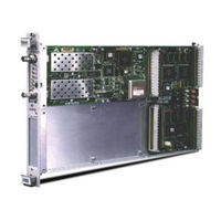
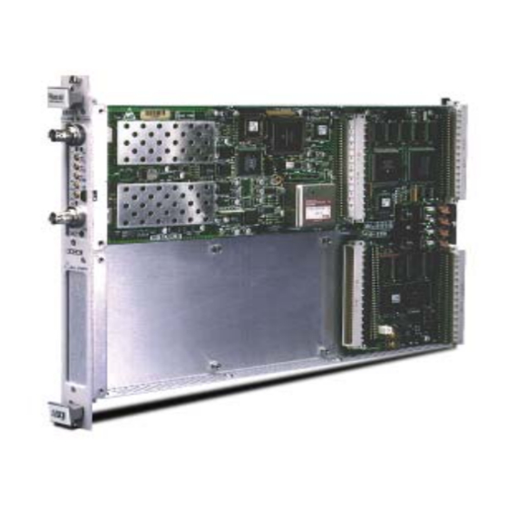
Racal Instruments 2461 User Manual (196 pages)
200MHz UNIVERSAL COUNTER TIMER Type C
Brand: Racal Instruments
|
Category: Timer
|
Size: 5 MB
Table of Contents
Advertisement
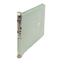
Racal Instruments 2461 Manual (64 pages)
VXI MODULAR INSTRUMENTATION
Brand: Racal Instruments
|
Category: Control Unit
|
Size: 22 MB