
Subscribe to Our Youtube Channel
Related Manuals for Fronius LaserHybrid Ultracompact Twin


Summary of Contents for Fronius LaserHybrid Ultracompact Twin
- Page 1 / Perfect Charging / Perfect Welding / Solar Energy Operating Instructions LaserHybrid Ultracompact Twin LaserHybrid 42,0426,0255,EN 003-16082017...
- Page 3 Thank you for the trust you have placed in our company and congratulations on buying this high-quality Fronius product. These instructions will help you familiarise yourself with the product. Reading the instructions carefully will enable you to learn about the many different features it has to offer.
-
Page 5: Table Of Contents
Contents Safety rules ..............................Explanation of safety symbols ......................General ..............................Proper use ............................Environmental conditions........................Obligations of the operator........................Obligations of personnel ........................Personal protective equipment ......................Danger from toxic gases and vapours ....................Danger from escaping shielding gas..................... Danger from flying sparks ........................ - Page 6 Requirements for the robot ........................Fitting the laser welding head to the robot .................... Connecting the LaserHybrid Ultracompact Twin hosepack to the laser welding head ......Preparatory work........................... Connecting the LaserHybrid Ultracompact Twin hosepack to the laser welding head ......
- Page 7 Example: Using the reference program after changing the welding torch ..........107 Measures to reduce optics contamination ....................108 Measures to reduce optics contamination .................... 108 Appendix Technical data............................113 LaserHybrid Ultracompact Twin(laser welding head) ................113 LaserHybrid Ultracompact Twin hosepack ................... 113 Spare parts list: LaserHybrid Ultracompact Twin ..................114...
-
Page 9: Safety Rules
Safety rules Explanation of DANGER! Indicates immediate and real danger. If it is not avoided, death or se- safety symbols rious injury will result. WARNING! Indicates a potentially dangerous situation. Death or serious injury may result if appropriate precautions are not taken. CAUTION! Indicates a situation where damage or injury could occur. -
Page 10: Proper Use
Proper use The LaserHybrid head is to be used exclusively for its intended purpose. The LaserHybrid head is intended solely for use in LaserHybrid welding of al- uminium, CrNi and steel materials. Any use above and beyond this purpose is deemed improper. The manufacturer shall not be held liable for any damage arising from such usage. -
Page 11: Obligations Of Personnel
Obligations of Before starting work, all persons using the LaserHybrid head undertake: personnel to observe the basic instructions regarding safety at work and accident prevention to read these operating instructions, especially the "Safety rules" section and sign to confirm that they have understood them and will follow them. Before leaving the workplace, ensure that people or property cannot come to any harm in your absence. -
Page 12: Danger From Escaping Shielding Gas
Otherwise, a protective mask with an air supply must be worn. Close the shielding gas cylinder valve or main gas supply if no welding is tak- ing place. If there is any doubt about whether the extraction capacity is sufficient, the measured toxic emission values should be compared with the permissible limit values. -
Page 13: Vagrant Welding Currents
Vagrant welding If the following instructions are ignored, vagrant welding currents may occur. currents These can destroy earthed conductor terminals, the power source being used, the LaserHybrid welding head and other electrical equipment. Ensure the workpiece clamp is connected tightly to the workpiece. On electrically conductive floors, the power source must be set up in such a way as to be insulated from the floor, wherever possible. -
Page 14: Specific Hazards
Specific hazards Risk of injury to the eyes from the laser beam. In addition to the protective visor with regulation UV filter element, ensure that all persons wear regulation laser safety goggles to protect their eyes from laser beams. You should still ensure that nobody can accidentally look into the laser beam. -
Page 15: Informal Safety Measures
Use only suitable load-carrying equipment supplied by the manufacturer when transporting devices by crane. Hook chains or ropes onto all suspension points provided on the load-car- rying equipment. Chains and ropes must be at the smallest angle possible to the vertical. Remove gas cylinder and wirefeeder (MIG/MAG and TIG devices). -
Page 16: Safety Measures In Normal Operation
When transporting the device, observe the relevant national and local guide- lines and accident prevention regulations. This applies especially to guidelines regarding the risks arising during transport. Before transporting the device, allow coolant to drain completely and detach the following components: Wire feed speed Wirespool Shielding gas cylinder... -
Page 17: Replacement And Wearing Parts
Calibration of In view of international standards, regular calibration of power sources is nec- power sources essary. Fronius recommends a 12-month calibration interval. For more infor- mation, please contact your service centre. CE marking The LaserHybrid head fulfils the fundamental requirements of the Low Voltage Directive and the Electromagnetic Compatibility Directive and is thus CE- marked. -
Page 19: General Information
General information... -
Page 21: General
Operating Instructions. Proper use/in- The LaserHybrid ultracompact Twin is intended exclusively for MAG tandem (Twin) weld- tended purpose ing. Utilisation for any other purpose, or in any other manner, shall be deemed to be not in ac- cordance with the intended purpose. -
Page 22: Application Areas
Application areas The LaserHybrid Ultracompact Twin laser welding head is primarily used in laser-MAG ap- plications: For axle and bodywork production with sheet thicknesses of 1 - 4 mm in the motor ve- hicle industry For tank and boiler manufacturing... -
Page 23: Laser Welding Head Scope Of Supply
Laser welding 1 LaserHybrid Ultracompact Twin laser welding head (complete) head scope of 1 LaserHybrid Ultracompact Twin hosepack supply 1 metal gauge for adjusting the focal spot 1 flat spanner (8/10 mm) 1 slotted screwdriver, 2.5 mm 1 Allen key, 2.5 mm... -
Page 24: Requirements
+ Official UST V3.10.33 firmware and higher + LHSB connection option + "TimeTwin Digital" software activation + Software update from the Fronius database + Standard I/O robot interface or fieldbus The options are required on both power sources. Drive Easy Twin control box... -
Page 25: Mechanical Requirements
Please note the following when dimensioning the robot: the robot The torch holder on the robot must be stable. A LaserHybrid Ultracompact Twin weld- ing head weighs roughly 10.4 kg. The CrashBox must be designed for the weight of the laser welding head. -
Page 26: Functional Principle
Functional principle Functional princi- (11) (10) Two wire electrodes (5) and (11) are welded by a laser beam (6) in a weld pool under a gas shroud. The welding process is performed using two independent power sources (4) and (10). The power sources (4) and (10) are synchronised (7). -
Page 27: Welding Technology Aspects
G3Si1-Twin M21 - 90% Ar, rest O 02-1920 02-1917 * ... Recommended by Fronius for the laser-twin welding process L ... Lead wire electrode T ... Trail wire electrode Earth connection Use a separate grounding (earthing) cable for each power source:... -
Page 28: Tilt Angle Of The Welding Torch
Tilt angle of the Select the welding torch tilt angle so that welding torch the lead wire electrode (= the electrode of the lead power source) is positioned neut- rally or slightly forward. 90 - 100° Welding torch tilt angle neutral to slightly forward Possible arc com- The LHSB connection on the power sources means that various arc types can be com- binations... - Page 29 Trail wire electrode Lead wire electrode Active pulsed arc with droplet transfer Inactive pulsed arc (no droplet transfer) Welding current of lead power source Welding current of trail power source Welding direction A "Master selection signal" is output by the robot control. This signal defines the lead power source.
-
Page 30: Connecting To The Robot Control
Connecting to the robot control Robot interfaces There are two special robot interfaces available for the laser-twin welding process, for con- for the laser-twin necting to the robot control: welding process Twin Standard I/O Job (0-24 V digital) Twin Standard I/O Synergic / Job (0-24 V digital, 0-10 V analogue) Each of these "Twin interfaces"... -
Page 31: Standard Robot Interfaces
Standard robot The following standard robot interfaces can be used to connect to the robot control for Twin interfaces processes: ROB 3000 (0-24 V digital) ROB 4000 (0-24 V digital, 0-10 V analogue) ROB 5000 (0-24 V digital, 0-10 V analogue) Signals must be connected logically by the robot control when standard robot interfaces are used. -
Page 32: Twin Fieldbus Systems
Twin fieldbus The following Twin fieldbus systems can be used to connect to the robot control for Twin systems processes: Twin DeviceNet fieldbus robot interface Twin CANopen fieldbus robot interface Twin Interbus CU fieldbus robot interface Twin Profibus fieldbus robot interface An integral PLC is also a feature of the "Twin fieldbus systems"... -
Page 33: Standard Fieldbus Systems
Standard fieldbus The following standard fieldbus systems can be used to connect to the robot control for systems Twin processes: DeviceNet fieldbus robot interface CanOpen fieldbus robot interface Interbus CU fieldbus robot interface Interbus LWL fieldbus robot interface Profibus 1.5 MB fieldbus robot interface Signals must be connected logically by the robot control when standard fieldbus systems are used. -
Page 35: Control Elements And Connections
Control elements and connections... -
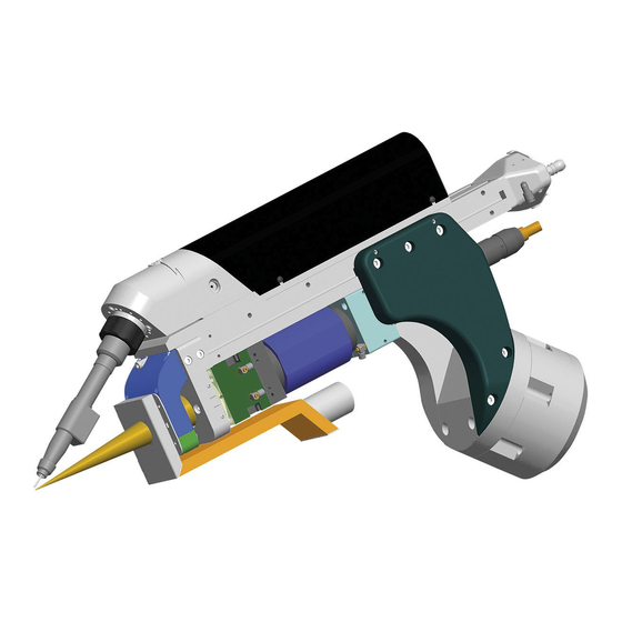
Page 37: Description Of The Device
Optional additional extractor (with corresponding spatter guard sheet) One of the two extractors is fitted prior to delivery depending on the configuration. Laser optics Radial air flow Gas nozzle LaserHybrid Ultracompact Twin welding torch Adjusting device Drive roller cover (10) Motor cover... - Page 38 Item Designation (12) Controls Wire retract button Wire threading button Gas-test button (13) Robot holder (14) Laser optics system water cooling connection (15) Wirefeeding hose connections (16) LaserHybrid Ultracompact Twin hosepack (17) CrashBox (option)
-
Page 39: Connection Specifications
Connection specifications Connection spec- ifications Item Designation Fibre optic cable for laser Bending radius > 100 mm IMPORTANT! Only use a fibre optic cable with fibres of </= 0.3 mm. Larger fibres can affect the welding result and cause damage to the laser welding head. -
Page 40: Compressed Air Diagram
Item Designation Laser optics system water cooling connection (of LaserHybrid interconnecting hosepack) External wirefeeding hose (Fronius) LaserHybrid interconnecting hosepack (Fronius) Hosepack incl. compressed air for Crossjet and radial air flow, water cooling for laser optics system and media coupling Compressed air... -
Page 41: Start-Up
Start-up... -
Page 43: General
General Safety WARNING! Work that is carried out incorrectly can cause serious injury and dam- age. Set up work must only be performed by trained and qualified personnel. Ob- serve the safety regulations in the operating instructions, paying particular attention to the section entitled "Safety inspection". Setup regulations The power sources are tested to protection class IP23, meaning: Protection against penetration by solid foreign bodies with diameters >... - Page 44 NOTE! The control unit must only be fitted to the power source using the optional holder from Fronius (item no. 4,100,719). Fit the Drive Easy Twin control box to the lead power source: Establish an LHSB connection between the power sources Connect the lead power source to the robot control Connect power source "1"...
-
Page 45: Commissioning (Overview)
Commissioning the laser welding head comprises the following sections: (overview) Fitting the laser welding head to the robot Connecting the LaserHybrid Ultracompact Twin hosepack to the laser welding head Connecting the laser optics system, Crossjet and additional extractor Laying the hosepack on the robot... -
Page 46: Fitting The Laser Welding Head To The Robot
NOTE! The laser welding head does not have collision protection as standard. welding head to Fronius therefore recommends using a commercial collision protection device for the robot robot applications to prevent the laser welding head being damaged in the event of a crash. -
Page 47: Connecting The Laserhybrid Ultracompact Twin Hosepack To The Laser Welding Head
Connecting the LaserHybrid Ultracompact Twin hosepack to the laser welding head Preparatory work Remove the two Allen screws (4 mm) Remove the media cover Remove the three Allen screws (2.5 mm) Remove the current interface cover Remove the Allen screw... -
Page 48: Connecting The Laserhybrid Ultracompact Twin Hosepack To The Laser Welding Head
Remove the Allen screw (3 mm) Pull the motor cover towards the rear and remove it Connecting the Feed in the hosepack LaserHybrid Ul- tracompact Twin hosepack to the laser welding head Push the hexagon nut over the media Lightly tighten the hexagon nut... - Page 49 IMPORTANT! Before tightening the hexa- gon nut, ensure the correct positioning of the media as shown in the illustration: The hoses (4) for cooling the laser op- tics are connected on the opposite side Power/coolant cable with red hose (3): Connection for trail electrode (T) Power/coolant cable with transparent hose (2):...
- Page 50 Fitting the strain-relief device Remove the Allen screw (3 mm) Position strain-relief device for the mo- tor line from the hosepack Fit the strain-relief device from the right using an Allen screw (3 mm) View from the robot to the laser welding head Position the robot connection flange (without control elements) Refit the robot connection flange using...
- Page 51 Connecting the media couplings IMPORTANT! Grease the screws before connecting the media couplings. Fit the two media couplings using an Allen screw (5 mm) Tightening torque = 8 Nm Power/coolant cable with transparent hose (2): Connection for lead electrode (L) Power/coolant cable with red hose (3): Connection for trail electrode (T) Connecting the motor line...
-
Page 52: Connect/Replace The External Wirefeeding Hoses On The Laser Welding Head
Connecting the cooling system for the laser optics Connect the flow and return hose for the laser optics water cooling system as shown Hose with blue markings (= water flow): Fitting the current interface cover Position the current interface cover Fit the current interface cover using three Allen screws (2.5 mm) -
Page 53: And Finally
Tighten the hexagon nuts until the sea- ling lip protrudes (24 mm) And finally... NOTE! When fitting the covers en- sure that cables are not trapped, crushed or damaged in any way. Insert the motor cover into the side recesses Secure the motor cover using an Allen screw (3 mm) -
Page 54: Connecting The Laser Optics System, Crossjet And Additional Extractor
Connecting the laser optics system, Crossjet and additional extractor Connecting the CAUTION! Risk of damage to the laser welding head due to contamination from laser optics sys- above. Observe the Operating Instructions, specifications and safety instructions set out by the laser optics system manufacturer Before connecting, position the laser welding head in relation to the horizon- tal so that no contaminants can enter the laser optics from above. - Page 55 Connect the fibre optic cable: Press the button on the underside Retract the rubber sleeve in the direc- tion of the optics Insert the fibre optic cable connector Check that the rubber sleeve forms a complete seal around the fibre optic cable connector IMPORTANT! The illustration on the right shows an incorrectly positioned...
-
Page 56: Connecting The Crossjet And Additional Extractor
Connecting the IMPORTANT! Confusing the Crossjet outlet air and additional extractor connections will Crossjet and ad- impair the protective function of the Crossjet. ditional extractor Connect the hoses for the Crossjet outlet air and additional extractor correctly. Connect the hoses for the Crossjet out- let air and additional extractor to the re- levant connections indicated in the connection specifications (e.g. -
Page 57: Laying The Hosepack On The Robot
Laying the hosepack on the robot Laying the hose- IMPORTANT! The optional LaserHybrid hosepack holder is not included in the scope of pack on the robot supply of the laser welding head. 6 x 4 Nm 44,0360,0099 4 Nm 4 Nm Robot arm Opening for fibre optic cable Profile support... -
Page 58: Threading The Wire Electrode
Threading the wire electrode Preparatory work Remove the two Allen screws (4 mm) Remove the media cover Remove the Allen screw (3 mm) Remove the Allen screw on the oppo- site side (3 mm) Pull the drive roller cover towards the rear and remove it Removing the welding torch... -
Page 59: Threading The Wire Electrode
Unscrew the contact tip adapter using an 8 mm box Remove the gas distributor spanner Threading the IMPORTANT! wire electrode The lead and trail wire electrodes must be threaded in before using the system for the first time. Depending on the circumstances, the lead or trail electrodes can be changed individ- ually or at the same time. - Page 60 Pull the pressure lever upwards Swivel the feed rollers downwards Thread the wire electrode into the inta- ke nozzle using needle-nosed pliers Swing in the feed rollers Push the pressure lever downwards...
- Page 61 Set the contact pressure: three rings must be visible (*) Press the wire threading button on the laser welding head until the wire elec- trodes protrude out of the welding torch Pull the pressure lever upwards Swivel the feed rollers downwards Close the feed rollers on the unreeling wirefeeder Set the torque mode on the unreeling wirefeeder Set the wirefeeder torque on the unreeling wirefeeder using the potentiometer:...
-
Page 62: Fitting The Welding Torch Wearing Parts
Swing in the feed rollers Push the pressure lever downwards Fitting the weld- IMPORTANT! The wire electrode must be threaded in when fitting the welding torch wear- ing torch wearing ing parts. parts Fit the gas distributor Screw in the contact tip adapter (8 mm box spanner) Tightening torque = 5 Nm IMPORTANT! When fitting the gas distributor, ensure that the recess on the gas... - Page 63 Screw in the contact tips Position the gas nozzle and secure using a 2.5 mm Al- (7 mm flat spanner) len key Tightening torque = 4 Nm Tightening torque = 1 Nm...
-
Page 64: Setting The Radial Air Flow
Setting the radial air flow Requirements IMPORTANT! The radial air flow must be set before switching on the laser welding head. The flow rate meter from the laser welding head scope of supply is required to set the radial air flow. Setting the radial Remove the two Allen screws air flow... - Page 65 Connect the hose and adapter from the laser welding head scope of supply Connect the hose Fit the flow rate meter to the hose and adapter Check whether the Crossjet supply complies with the given specification Switch on the Crossjet Set the flow rate to 25 l/min using a small slotted screwdriver Remove the flow rate meter...
- Page 66 Connect the air hose Swing in the additional extractor Fit the additional extractor using two Allen screws (3 mm)
-
Page 67: Adjusting The Laser Welding Head
Adjusting the laser welding head Stick out NOTE! When setting the physical position of the welding torch, en- sure that the stick out is always 18 Welding torch Contact tip Stick out of lead electrode 18 mm (relative to the focal length of the laser optics) Stick out of trail electrode (deter- mined by the torch settings) -
Page 68: Adjusting Device On The Laser Welding Head
Adjusting device The laser welding head is fitted with an adjusting device that enables precise positioning on the laser weld- in the x and y coordinate axes. ing head The adjusting device comprises: Adjusting screw with pitch Allen screw (3 mm), quarter turn corresponds to an ad- justment of 0.25 mm Scale denoting adjustment range... -
Page 69: Adjusting The Y-Axis
Adjusting the y- NOTE! The y setting range of ± 3 axis mm starts from the second gradu- ation mark on the y scale. In position 0, both the laser and wire electrode would fall on the same exact location. Laser beam - 3 mm + 3 mm... -
Page 70: Creating A Reference Program
Creating a reference program Safety WARNING! Work that is carried out incorrectly can cause serious injury and dam- age. Set up work must only be performed by trained and qualified personnel. Ob- serve the safety regulations in the operating instructions, paying particular attention to the section entitled "Safety inspection". - Page 71 Save the settings as a reference program in the robot Perform a trial weld The best welding result will be used as the basis for the reference program. If changes to the mechanical x/y settings are required as a result of the trial weld, over- write the reference program initially created...
-
Page 72: Signal Sequence For Laserhybrid Welding
Signal sequence for LaserHybrid welding Safety WARNING! Work that is carried out incorrectly can cause serious injury or dam- age. The welding sequence must only be programmed by trained specialist per- sonnel. Observe the safety rules in the operating instructions, paying particular attention to the section entitled "Safety inspection". - Page 73 LaserHybrid welding start position: Requirement: the laser must be ready to enable the beam. Set the "arc on" signal Wait for the current flow signal ("arc on") Set the "laser on" signal Set the "robot start" signal The distance between the laser and the wire electrode should be 1 - 5 mm depending on the process.
-
Page 74: Measures To Be Taken Before The Start Of Welding
Measures to be taken before the start of welding Measures to be Check the coolant flow on the laser optics cooling system taken before the Check the coolant flow on the welding torch cooling system start of welding (visual inspection in the coolant tank on the cooling unit) Check whether protective glass is present in the laser optics system Test the Crossjet Test the extractor... -
Page 75: Recommendations For Operating A Laser-Twin Welding System
Recommendations for operating a laser-twin weld- ing system Recommenda- To ensure smooth operation, the following items must always be available for a laser-twin tions for operat- welding system: ing a laser-twin welding system Laser-twin service station Compressed-air gun supply at 6 bar Portable tool trolley with the following tools and spare parts: 20 x 1.0 mm contact tips 20 x 1.2 mm contact tips... -
Page 77: Maintenance
Maintenance... -
Page 79: Changing The Wire Electrode
Changing the wire electrode Preparatory work Remove the two Allen screws (4 mm) Remove the media cover Remove the Allen screw (3 mm) Remove the Allen screw on the oppo- site side (3 mm) Pull the drive roller cover towards the rear and remove it... -
Page 80: Unthreading The Wire Electrode
Unthreading the IMPORTANT! wire electrode Depending on the circumstances, the lead or trail electrodes can be changed individ- ually or at the same time. Read and observe the safety rules, safety instructions and all documentation relating to the unreeling wirefeeders. Requirement: 2 x stand-alone unreeling wirefeeders (e.g. - Page 81 Unscrew the contact tip adapter Remove the gas distributor Set the wire threading mode on the unreeling wirefeeder Open the feed rollers on the unreeling wirefeeder Fully open the adjusting screw * Fully open Pull the pressure lever upwards Swivel the feed rollers downwards Manually remove the wire electrode on the unreeling wirefeeder...
-
Page 82: Changing The Wire Electrode
Changing the IMPORTANT! When performing any activities on unreeling wirefeeders, read and observe wire electrode the safety rules, safety instructions and all documentation relating to the unreeling wire- feeders. Remove the unreeling wirefeeder from the empty welding wire drum Replace the welding wire drum Fit the unreeling wirefeeder to the new welding wire drum Thread the wire electrode into the laser welding head (see "Threading in the wire electrode"... -
Page 83: Replacing Wearing Parts
Replacing wearing parts Preparatory work Remove the two Allen screws (4 mm) Remove the media cover Remove the Allen screw (3 mm) Remove the Allen screw on the oppo- site side (3 mm) Pull the drive roller cover towards the rear and remove it Removing the Fully open the adjusting screw... - Page 84 Swivel the pressure lever upwards Push the feed rollers downwards Cut the wire electrodes at the outlet nozzles of the wirefeeding hoses Remove the wire electrodes from the welding torch...
- Page 85 Remove the M4 screw Position the M6 Allen screw Screw in the M6 Allen screw The side panel will come loose. Remove the side panel Remove the bottom feed rollers...
-
Page 86: Replacing The Inlet Nozzles
Position the slotted screwdriver bet- ween the top feed rollers and the side wall Press out the top feed rollers using the slotted screwdriver Remove the top feed rollers Replacing the in- Removal: let nozzles Remove the inlet nozzles using need- le-nosed pliers Installation: Insert the inlet nozzles using needle-... - Page 87 The subsequent steps for installing the feed rollers are carried out in the reverse order to the steps for removal (see page 85, step 6 onwards).
-
Page 88: Replacing The Welding Torch And Welding Torch Inner Liners
Replacing the welding torch and welding torch inner liners Safety CAUTION! A welding torch that has become very hot through use can cause se- vere burns. The welding torch must only be cleaned and its components checked when it is cool. Preparatory work Remove the two Allen screws (4 mm) -
Page 89: Replace The Welding Torch
Replace the weld- Remove the two Allen screws ing torch (5 mm) Disconnect the two media couplings L = Lead electrode T = Trail electrode CAUTION! Risk of damage due to falling parts! Ensure that the welding torch does not fall when undoing the screws. -
Page 90: Replacing The Welding Torch Inner Liners
Replacing the IMPORTANT! The welding torch inner liners can only be replaced when the welding torch welding torch in- has been removed. ner liners Remove the welding torch (see pages 88 and 89) Pull out the inner liners Push in the new inner liners IMPORTANT! The replacement inner liners are preconfigured to the correct length. -
Page 91: Replacing Welding Torch Wearing Parts
Replacing welding torch wearing parts Safety CAUTION! A welding torch that has become very hot through use can cause se- vere burns. The welding torch must only be cleaned and its components checked when it is cool. Welding torch spare parts Removing the welding torch wearing parts... - Page 92 Unscrew the contact tip adapter using an 8 mm box Remove the gas distributor spanner Unscrew the nozzle fittings using an 11 mm box span-...
-
Page 93: Fitting The Welding Torch Wearing Parts
Fitting the weld- IMPORTANT! The wire electrode must be threaded in when fitting the welding torch wear- ing torch wearing ing parts. parts Screw in the nozzle fittings Fit the gas distributor (11 mm box spanner) Tightening torque = 6 Nm IMPORTANT! When fitting the gas distributor, ensure that the recess on the gas distributor is positioned above the raised element on the welding torch. - Page 94 Position the gas nozzle and secure using a 2.5 mm Al- len key Tightening torque = 1 Nm...
-
Page 95: Replacing The Spatter Guard Sheet
Replacing the spatter guard sheet Removing the Remove the two Allen screws spatter guard (3 mm) plate Push the spatter guard plate back- wards and remove it Fitting the spatter Slot in the spatter guard plate and push guard plate it forwards... - Page 96 Fit the spatter guard plate using two Al- len screws (3 mm)
-
Page 97: Replacing The Laser Optics System
Replacing the laser optics system Safety WARNING! Work that is carried out incorrectly can cause serious injury and dam- age. Installation must only be carried out by trained and qualified personnel. Ob- serve the safety regulations in the operating instructions, paying particular attention to the section entitled "Safety inspection". -
Page 98: Removing The Laser Optics System
Removing the la- Note: ser optics system The numbering of the arrows in the illustrations may differ from the work steps. Remove the two Allen screws (4 mm) Remove the media cover Remove the two Allen screws (3 mm) Push the spatter guard plate back- wards and remove it Unscrew the extraction pipe (28 mm) - Page 99 Remove the two Allen screws (3 mm) Swivel the additional extractor to one side Disconnect the air hose Remove the two Allen screws (3 mm)
- Page 100 Pull the Crossjet forwards Remove the four Allen screws from the underside of the laser welding head (2.5 mm) Disconnect the coolant hose...
-
Page 101: Mounting Positions For Installing The Laser Optics System
Remove the two Allen screws (16) and (17) (3 mm) (16) (17) Undo the two Allen screws (17) and (18) (3 mm) Remove the laser optics system by pulling it upwards (17) (18) Mounting posi- tions for install- ing the laser optics system e.g. -
Page 102: Installing The Laser Optics System
Installing the la- IMPORTANT! When replacing the laser optics system, ensure that the laser optics system ser optics system and the welding torch correspond in terms of the focal length. Note: The numbering of the arrows in the illustrations may differ from the work steps. IMPORTANT! When inserting the laser op- tics system, ensure that the pins on the un- derside of the laser optics system are... - Page 103 Connect the coolant hose Insert the Crossjet from the front Secure the Crossjet with two Allen screws (3 mm)
- Page 104 Connect the air hose Screw in the extraction pipe (28 mm) Swing in the additional extractor Fit the additional extractor using two Allen screws (3 mm)
-
Page 105: Fitting The Spatter Guard Plate
Fitting the spatter Slot in the spatter guard plate and push guard plate it forwards Fit the spatter guard plate using two Al- len screws (3 mm) And finally... Note: The numbering of the arrows in the illustrations may differ from the work steps. Position the media cover Secure the media cover using two Al- len screws... -
Page 106: Creating A Reference Program And Setting The Position Of The Wire Electrode In Relation To The Focus Point Of The Laser
Creating a reference program and setting the posi- tion of the wire electrode in relation to the focus point of the laser Safety WARNING! Work that is carried out incorrectly can cause serious injury and dam- age. Set up work must only be performed by trained and qualified personnel. Ob- serve the safety regulations in the operating instructions, paying particular attention to the section entitled "Safety inspection". -
Page 107: Example: Using The Reference Program After Changing The Welding Torch
Example: Using Switch off the power source the reference pro- Change the welding torch gram after chang- Welding torch change complete, wearing parts fitted: ing the welding Switch on the power source torch Set the stick out for the lead and trail wire electrode to 15 mm Upload the reference program and slowly move the robot to the reference point on the adjusting gauge Thread in the wire electrodes until they are touching the adjusting gauge... -
Page 108: Measures To Reduce Optics Contamination
Measures to reduce optics contamination Measures to re- Crossjet and extractor duce optics con- tamination Observe the values specified in these Operating Instructions for the Crossjet and ex- tractor. Switch on the Crossjet and extractor at least five seconds before the start of welding. Only switch off the Crossjet and extractor when the laser welding head is in the smoke- free zone. - Page 109 Dispose of the protective glass contaminated with welding spatter. At the start of production, check the protective glass regularly to determine an appli- cation-specific replacement interval. Automated torch cleaning device 10. When using an automated torch cleaning device: switch off the Crossjet and extractor during the cleaning process. Changing the fibre optic cable 11.
-
Page 111: Appendix
Appendix... -
Page 113: Technical Data
141 V Hosepack length 7.5 m Cooling system Liquid cooling Coolant Original Fronius coolant Lowest cooling capacity in accordance with IEC 60974-2, 1800 W depending on the length of the hosepack Min./max. coolant pressure 3.0 / 5.5 bar Min. coolant flow 1.0 l/min... -
Page 114: Spare Parts List: Laserhybrid Ultracompact Twin
Spare parts list: LaserHybrid Ultracompact Twin... - Page 120 FRONIUS INTERNATIONAL GMBH Froniusplatz 1, A-4600 Wels, Austria Tel: +43 (0)7242 241-0, Fax: +43 (0)7242 241-3940 E-Mail: sales@fronius.com www.fronius.com www.fronius.com/addresses Under http://www.fronius.com/addresses you will find all addresses of our Sales & service partners and Locations...
Need help?
Do you have a question about the LaserHybrid Ultracompact Twin and is the answer not in the manual?
Questions and answers