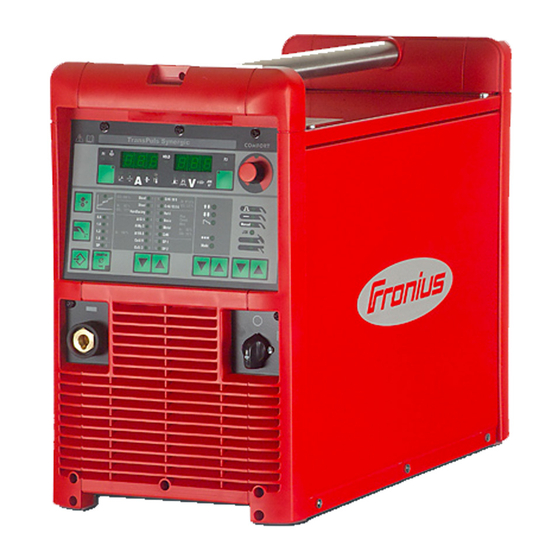
Fronius TransSynergic 4000 Operating Instructions Manual
Mig/mag power source
Hide thumbs
Also See for TransSynergic 4000:
- Operating instructions manual (309 pages) ,
- Service manual (140 pages) ,
- Operating instructions & spare parts (212 pages)
Table of Contents
Advertisement
/ Perfect Charging / Perfect Welding / Solar Energy
TransSynergic 4000/5000
TransPuls Synergic 2700
TransPuls Synergic
3200/4000/5000
TIME 5000 Digital
CMT 4000 Advanced
42,0426,0001,EN 023-17092020
Fronius prints on elemental chlorine free paper (ECF) sourced from certified sustainable forests (FSC).
Operating instructions
MIG/MAG power source
Advertisement
Table of Contents
Troubleshooting

Related Manuals for Fronius TransSynergic 4000


Summary of Contents for Fronius TransSynergic 4000
- Page 1 / Perfect Charging / Perfect Welding / Solar Energy Operating instructions TransSynergic 4000/5000 TransPuls Synergic 2700 MIG/MAG power source TransPuls Synergic 3200/4000/5000 TIME 5000 Digital CMT 4000 Advanced 42,0426,0001,EN 023-17092020 Fronius prints on elemental chlorine free paper (ECF) sourced from certified sustainable forests (FSC).
-
Page 2: Parameters For Operating Power Sources In Parallel In The Setup Menu Level
Toowoomba Welding Supplies : tweld.com.au : Ph +61 7 4659 0044... -
Page 3: Table Of Contents
Contents Safety rules Explanation of safety notices General Proper use Environmental conditions Obligations of the operator Obligations of personnel Mains connection Protecting yourself and others Noise emission values Danger from toxic gases and vapours Danger from flying sparks Risks from mains current and welding current Meandering welding currents EMC Device Classifications EMC measures... - Page 4 Key combinations - special functions Displaying the feeder inching speed Displaying the gas pre-flow and gas post-flow time Displaying the software version Comfort / CrNi / Steel control panel Difference between Comfort, CrNi and Steel control panels Comfort control panel Key combinations - special functions Displaying the feeder inching speed Displaying the gas pre-flow and gas post-flow time...
- Page 5 Setup regulations Mains connection Connecting up the mains cable on US power sources General Stipulated mains cables and strain-relief devices Safety Connecting the mains cable Replacing the strain-relief device Start-up Safety Remarks on the cooling unit Information on system components Overview Commissioning the TPS 2700 General...
- Page 6 Available parameters MIG/MAG standard manual welding Corrections during welding Adjusting parameters for correction CMT welding General CMT welding Corrections during welding Adjusting parameters for correction Special functions and options Arc break watchdog function Ignition time-out function Spatter-free ignition option SynchroPulse option Robot welding Prerequisite General...
- Page 7 Protective gas shield setup menu for the standard control panel Protective gas shield setup menu for the Comfort, US, TIME 5000 Digital and CMT control panels Welding parameters in the Protective gas shield setup menu Setup menu for the standard control panel General Setup menu for the standard control panel Parameters in the Setup menu for the Standard control panel...
- Page 8 Special voltages TPS 2700 TPS 2700 MV TPS 3200 TPS 3200 MV TPS 3200 460 V AC TS/TPS 4000 TS/TPS 4000 MV TS/TPS 5000 TS/TPS 5000 MV Technical data - US devices Technical data - Alu edition, CrNi edition, Yard edition and CMT variants TIME 5000 Digital CMT 4000 Advanced CMT 4000 Advanced MV...
-
Page 9: Safety Rules
Safety rules Explanation of DANGER! safety notices Indicates immediate danger. ▶ If not avoided, death or serious injury will result. WARNING! Indicates a potentially hazardous situation. ▶ If not avoided, death or serious injury may result. CAUTION! Indicates a situation where damage or injury could occur. ▶... -
Page 10: Environmental Conditions
The device is intended solely for the welding processes specified on the rating plate. Any use above and beyond this purpose is deemed improper. The manufacturer shall not be held liable for any damage arising from such usage. Proper use includes: carefully reading and following all the instructions given in the operating instructions studying and obeying all safety and danger notices carefully performing all stipulated inspection and maintenance work. -
Page 11: Protecting Yourself And Others
This may affect a number device types in terms of: Connection restrictions Criteria with regard to the maximum permissible mains impedance Criteria with regard to the minimum short-circuit power requirement at the interface with the public grid see "Technical data" In this case, the plant operator or the person using the device should check whether the device may be connected, where appropriate by discussing the matter with the power supply company. -
Page 12: Danger From Toxic Gases And Vapours
Danger from The fumes produced during welding contain harmful gases and vapours. toxic gases and Welding fumes contain substances that cause cancer, as stated in Monograph 118 of the vapours International Agency for Research on Cancer. Use at-source extraction and a room extraction system. If necessary, use a welding torch with an integrated extraction device. -
Page 13: Risks From Mains Current And Welding Current
Risks from mains An electric shock is potentially life threatening and can be fatal. current and weld- Do not touch live parts either inside or outside the device. ing current During MIG/MAG welding and TIG welding, the welding wire, the wirespool, the feed rollers and all pieces of metal that are in contact with the welding wire are live. -
Page 14: Meandering Welding Currents
Meandering weld- If the following instructions are ignored, meandering welding currents can develop with ing currents the following consequences: Fire hazard Overheating of parts connected to the workpiece Irreparable damage to ground conductors Damage to device and other electrical equipment Ensure that the workpiece is held securely by the workpiece clamp. -
Page 15: Emf Measures
Shielding, if necessary Shield off other nearby devices Shield off entire welding installation EMF measures Electromagnetic fields may pose as yet unknown risks to health: effects on the health of others in the vicinity, e.g. wearers of pacemakers and hear- ing aids wearers of pacemakers must seek advice from their doctor before approaching the device or any welding that is in progress... -
Page 16: Requirement For The Shielding Gas
Hook chains and/or ropes onto all suspension points provided on the load-carrying equipment. Chains and ropes must be at the smallest angle possible to the vertical. Remove gas cylinder and wire-feed unit (MIG/MAG and TIG devices). If the wire-feed unit is attached to a crane holder during welding, always use a suitable, insulated wirefeeder hoisting attachment (MIG/MAG and TIG devices). -
Page 17: Danger From Escaping Shielding Gas
The manufacturer's instructions must be observed as well as applicable national and international regulations for shielding gas cylinders and accessories. Danger from Risk of suffocation from the uncontrolled escape of shielding gas escaping shield- Shielding gas is colourless and odourless and, in the event of a leak, can displace the ing gas oxygen in the ambient air. -
Page 18: Commissioning, Maintenance And Repair
Before switching on the device, ensure that no one is likely to be endangered. Check the device at least once a week for obvious damage and proper functioning of safety devices. Always fasten the shielding gas cylinder securely and remove it beforehand if the device is to be transported by crane. -
Page 19: Disposal
(e.g. relevant product standards of the EN 60 974 series). Fronius International GmbH hereby declares that the device is compliant with Directive 2014/53/EU. The full text on the EU Declaration of Conformity can be found at the follow- ing address: http://www.fronius.com... - Page 20 Toowoomba Welding Supplies : tweld.com.au : Ph +61 7 4659 0044...
-
Page 21: General Information
General information Toowoomba Welding Supplies : tweld.com.au : Ph +61 7 4659 0044... - Page 22 Toowoomba Welding Supplies : tweld.com.au : Ph +61 7 4659 0044...
-
Page 23: General
General Device concept The TransSynergic (TS) 4000 and TS 5000 and TransPulsSynergic (TPS) 2700, TPS 3200, TPS 4000 and TPS 5000 power sources are fully digitised micropro- cessor-controlled inverter power sources. The modular design and potential for sys- tem add-ons ensure a high degree of flex- ibility. -
Page 24: Warning Notices On The Device
Warning notices US power sources come with extra warning notices affixed to the unit. The warning on the device notices must NOT be removed or painted over. Nur vorhanden bei Stromquelle „TPS 2700“ und auf Drahtvorschüben Toowoomba Welding Supplies : tweld.com.au : Ph +61 7 4659 0044... -
Page 25: Description Of Warning Notices On The Device
Description of On certain device versions, warning notices are attached to the device. Warning Notices on the Device The arrangement of the symbols may vary. Warning! Watch Out! There are possible hazards as shown by the symbols. Drive rolls can injure fingers. Welding wire and drive parts are at welding voltage during operation Keep hands and metal objects away. - Page 26 Welding sparks can cause explosion or fire. Keep flammables away from welding. Don’t weld near flammables. Welding sparks can cause fires.Have a fire extinguisher nearby and have a watchperson ready to use it. Do not weld on drums or any closed containers. Arc rays can burn eyes and injure skin.
-
Page 27: Special Versions
Special versions General Professional processing of specific materials requires welding programs that are spe- cially matched to the different materials in question. The special versions of the digital power sources are perfectly matched to these requirements. As a result the most import- ant welding programs can be called up directly from the operating panel. -
Page 28: Cmt 4000 Advanced
CMT 4000 In addition to the conventional MIG/MAG welding processes, MMA welding and the CMT Advanced process, the CMT 4000 Advanced power source supports the improved CMT Advanced process. The functional principle of the CMT Advanced process is based on a combination arc with negatively polarised CMT cycles and positively polarised CMT cycles or positively polarised pulse cycles. -
Page 29: System Components
System components General Digital power sources can be run with various system components and options. This makes it possible to optimise procedures and to simplify machine handling and opera- tion, as necessitated by the particular field of application in which the power source is to be used. - Page 30 Toowoomba Welding Supplies : tweld.com.au : Ph +61 7 4659 0044...
-
Page 31: Control Elements And Connections
Control elements and connections Toowoomba Welding Supplies : tweld.com.au : Ph +61 7 4659 0044... - Page 32 Toowoomba Welding Supplies : tweld.com.au : Ph +61 7 4659 0044...
-
Page 33: Description Of The Control Panels
Description of the control panels General The functions on the control panels are all arranged in a logical way. The various welding parameters can easily be selected using buttons and can just as easily be altered using buttons or the adjusting dial displayed on the digital display during welding The synergic function ensures that all other welding parameters are adjusted when an individual parameter has been changed. -
Page 34: Standard Control Panel
Standard control panel General NOTE! On the Standard control panel, only the MIG/MAG standard synergic welding pro- cess is available. The following processes and functions are not available and cannot be retrofitted: ▶ MIG/MAG pulse synergic welding ▶ Job mode ▶... - Page 35 Function Feeder inching button for feeding the wire electrode into the torch‑hosepack without any flow of gas or current For information on the various wire feed sequences that are possible when the welder presses and holds the "Feeder inching" button, see the Fdi parameter in the Setup menu.
-
Page 36: Key Combinations - Special Functions
Function (12) Material button for selecting the filler metal and shielding gas to be used. Parameters SP1 and SP2 are reserved for additional materials. When a material is selected, the LED behind the relevant filler metal lights up. (13) Wire diameter button for selecting the diameter of the wire to be used. -
Page 37: Displaying The Software Version
Displaying the In addition to the software version, these special functions can also be used to display software version the version number of the welding database, the wire-feed unit number, the software version of the wire-feed unit and the arc burning time. The software version is displayed Press the Material button (12) to display the version number of the welding database... -
Page 38: Comfort / Crni / Steel Control Panel
Comfort / CrNi / Steel control panel Difference The Comfort, CrNi and Steel control panels are identical except for the type of material between Comfort, used in their construction. The following section deals specifically with the Comfort con- CrNi and Steel trol panel, but all the functions described apply equally to the CrNi and Steel control pan- control panels els. - Page 39 Function Keylock switch (optional) When the key is in the horizontal position, the following functions are dis- abled: Selecting the welding process using the Process button(s) (22) Selecting the mode using the Mode button(s) (23) Selecting the filler metal using the Material button(s) (24) Opening the Setup menu using the Store button (27) Opening the job correction menu (see “Job mode”) NOTE! The functions available on the control panel of system com-...
- Page 40 Function (10) Wire feed speed LED lights up when the wire feed speed parameter is selected (11) Overtemperature indicator lights up if the power source overheats (e.g. because the duty cycle has been exceeded). For more information on this, see the "Troubleshooting" section. (12) HOLD indicator every time a welding operation finishes, the actual values for welding current...
- Page 41 Function (20) Parameter selection button for selecting the following parameters: Arc length correction for correcting the arc length Droplet detachment correction/arc force dynamic correction/arc force dynamic has a different function assigned to it, depending on the process being used. A description of the various functions can be found in the Welding chapter under the corresponding process.
-
Page 42: Key Combinations - Special Functions
Function (23) Mode button for selecting the mode 2-step mode 4-step mode Special 4-step mode (aluminium welding start-up) Spot welding mode Operating mode When a mode is selected, the LED behind the relevant symbol lights up. (24) Material button for selecting the filler metal and shielding gas to be used. Parameters SP1 and SP2 are reserved for additional materials. -
Page 43: Displaying The Gas Pre-Flow And Gas Post-Flow Time
Displaying the The set gas pre-flow time is displayed (e.g. GPr | 0.1 s) gas pre-flow and gas post-flow time Use the adjusting dial to change the gas pre-flow time Then press the Process button (22) to display the gas post-flow time setting (e.g. -
Page 44: Us Control Panel
US control panel US control panel (10) (12) (14) (16) (18) (11) (13) (15) (17) (19) (25) (23) (21) (26) (24) (22) (20) Function Inch Forward (feeder inching) button for feeding the wire electrode into the torch‑hosepack with no accompanying flow of gas or current For information on the various wire feed sequences that are possible when the welder presses and holds the "Feeder inching"... - Page 45 Function Parameter selection button for selecting the following parameters: Sheet thickness Sheet thickness in mm or in. Welding current Welding current in A Before the start of welding, the machine automatically displays a standard value based on the programmed parameters. During weld- ing, the actual value is displayed.
- Page 46 Function (14) Welding voltage LED lights up when the welding voltage parameter is selected (15) Right digital display (16) Job no. LED lights up when the job number parameter is selected (17) F3 indicator LED lights up when the F3 indicator parameter is selected (18) Parameter selection button for selecting the following parameters:...
-
Page 47: Key Combinations - Special Functions
Function (21) Mode button for selecting the mode 2-step mode 4-step mode Special 4-step mode (aluminium welding start-up) Spot welding mode Operating mode When a mode is selected, the LED behind the relevant symbol lights up. (22) Material button for selecting the filler metal and shielding gas to be used. Parameters SP1 and SP2 are reserved for additional materials. -
Page 48: Displaying The Gas Pre-Flow And Gas Post-Flow Time
Displaying the The set gas pre-flow time is displayed (e.g. GPr | 0.1 s) gas pre-flow and gas post-flow time Use the adjusting dial to change the gas pre-flow time Then press the Process button (20) to display the gas post-flow time setting (e.g. -
Page 49: Time 5000 Digital Control Panel
TIME 5000 Digital control panel TIME 5000 Digital (10) (12) (14) (16) (18) (20) control panel (11) (13) (15) (17) (19) (21) (27) (25) (23) (28) (26) (24) (22) Function Inch Forward (feeder inching) button for feeding the wire electrode into the torch‑hosepack with no accompanying flow of gas or current For information on the various wire feed sequences that are possible when the welder presses and holds the "Feeder inching"... - Page 50 Function Parameter selection button for selecting the following parameters: a-dimension depending on the set welding speed Sheet thickness Sheet thickness in mm or in. Welding current Welding current in A Before the start of welding, the machine automatically displays a standard value based on the programmed parameters.
- Page 51 Function (14) Droplet detachment correction/arc force dynamic correction/arc force dynamic LED lights up when the Droplet detachment correction/arc force dynamic correction/arc force dynamic parameter is selected (15) Welding voltage LED lights up when the welding voltage parameter is selected (16) Welding speed LED lights up when the welding speed parameter is selected (17)
-
Page 52: Key Combinations - Special Functions
Function (22) Process button(s) for selecting the welding process MIG/MAG pulse synergic welding MIG/MAG standard synergic welding MIG/MAG standard manual welding Job mode TIG welding with touchdown ignition Manual metal arc welding When a process is selected, the LED on the relevant symbol lights up. (23) Mode button for selecting the mode... -
Page 53: Displaying The Feeder Inching Speed
Displaying the The set feeder inching speed is shown feeder inching (e.g.: Fdi | 10 m/min or Fdi | 393.70 ipm). speed Use the adjusting dial to change the feeder inching speed Press the Store button to exit. Displaying the The set gas pre-flow time is displayed (e.g. -
Page 54: Cmt Control Panel
CMT control panel CMT control (10) (12) (14) (16) (18) panel (11) (13) (15) (17) (24) (22) (20) (25) (23) (21) (19) Function Inch Forward (feeder inching) button for feeding the wire electrode into the torch‑hosepack with no accompanying flow of gas or current For information on the various wire feed sequences that are possible when the welder presses and holds the "Feeder inching"... - Page 55 Function F1 indicator indicates that the PushPull drive is switched on Wire-feed unit drive current-input indicator indicates that the wire-feed unit drive is switched on If the indicators are lit up on the parameter selection button (3) and on the adjusting dial (19), then the indicated / selected parameter can be altered using the adjusting dial (19).
- Page 56 Function (17) Parameter selection button for selecting the following parameters: Arc length correction for correcting the arc length Droplet detachment correction/arc force dynamic correction/arc force dynamic has a different function assigned to it, depending on the process being used. A description of the various functions can be found in the Welding chapter under the corresponding process.
-
Page 57: Key Combinations - Special Functions
Function (21) Material button for selecting the filler metal and shielding gas to be used. Parameters SP1 and SP2 are reserved for additional materials. When a material is selected, the LED behind the relevant filler metal lights up. (22) Diameter / Index (wire diameter) button for selecting the diameter of the wire to be used. -
Page 58: Displaying The Software Version
Displaying the In addition to the software version, these special functions can also be used to display software version the version number of the welding database, the wire-feed unit number, the software ver- sion of the wire-feed unit and the arc burning time. The software version is displayed Press the Material button (24) to display the version number of the welding database... -
Page 59: Yard Control Panel
Yard control panel Yard control (10) (12) (14) (16) (18) panel (11) (13) (15) (17) (24) (22) (20) (25) (23) (21) (19) Function Inch Forward (feeder inching) button for feeding the wire electrode into the torch‑hosepack with no accompanying flow of gas or current For information on the various wire feed sequences that are possible when the welder presses and holds the "Feeder inching"... - Page 60 Function Parameter selection button for selecting the following parameters: Sheet thickness Sheet thickness in mm or in. Welding current Welding current in A Before the start of welding, the machine automatically displays a standard value based on the programmed parameters. During weld- ing, the actual value is displayed.
- Page 61 Function (13) Welding voltage LED lights up when the welding voltage parameter is selected (14) Right digital display (15) Job no. LED lights up when the job number parameter is selected (16) F3 indicator LED lights up when the F3 indicator parameter is selected (17) Parameter selection button for selecting the following parameters:...
-
Page 62: Key Combinations - Special Functions
Function (20) Mode button for selecting the mode 2-step mode 4-step mode Special 4-step mode (aluminium welding start-up) Spot welding mode Operating mode When a mode is selected, the LED behind the relevant symbol lights up. (21) Material button for selecting the filler metal and shielding gas to be used. Parameters SP1 and SP2 are reserved for additional materials. -
Page 63: Displaying The Gas Pre-Flow And Gas Post-Flow Time
Displaying the The set gas pre-flow time is displayed (e.g. GPr | 0.1 s) gas pre-flow and gas post-flow time Use the adjusting dial to change the gas pre-flow time Then press the Process button (20) to display the gas post-flow time setting (e.g. -
Page 64: Remote" Control Panel
“Remote” control panel General The Remote operating panel is fitted to the Remote power source. The Remote power source is designed for automated and robot applications and is controlled exclusively via the LocalNet. The Remote power source can be operated via the following system add-ons: Remote controls Robot interfaces Field bus systems... -
Page 65: Cmt Remote Control Panel
CMT Remote control panel General The CMT Remote control panel is fitted to the CMT Remote power source and CMT Advanced power source. The CMT Remote power source and CMT Advanced power source are designed for automated and robot applications and are controlled exclusively via the LocalNet. -
Page 66: Connections, Switches And Mechanical Components
Connections, switches and mechanical compon- ents TPS 2700 power (7) (8) source Front view / Rear view / Side view Function LocalNet connection Standardised connection socket for system add-ons (e.g. remote control, Job- Master torch, etc.) (+) - Current socket with bayonet latch for: connecting the grounding (earthing) cable during TIG welding connecting the electrode cable or grounding (earthing) cable during MMA... -
Page 67: Tps 2700 Cmt Power Source
Function (12) 4 roller drive TPS 2700 CMT (7) (8) power source (11) (10) (12) (13) Front view / Rear view / Side view Function LocalNet connection Standardised connection socket for system add-ons (e.g. remote control, Job- Master torch, etc.) Motor control connection for connecting the control line from the CMT drive unit Welding torch control connection... -
Page 68: Ts 4000 / 5000, Tps 3200 / 4000 / 5000, Time 5000 Digital Power Sources
Function (11) Mains cable with strain relief device (12) Wirespool holder with brake for holding standard wirespools weighing up to 16 kg (35.27 lbs) and with a max. diameter of 300 mm (11.81 in) (13) 4 roller drive TS 4000 / 5000, TPS 3200 / 4000 / 5000, TIME 5000 Digital power... -
Page 69: Cmt 4000 Advanced Power Source
Function Second (-) - Current socket with bayonet latch (optional) for: connecting the interconnecting hosepack in MIG/MAG welding for polar- ity reversal (e.g. for innershield and flux core wire welding) specially for automated and robot applications where the interconnecting hosepack and grounding (earthing) cable are to be connected to one side of the power source (e.g. - Page 70 Function Current socket with bayonet latch for: connecting the current cable of the interconnecting hosepack in MIG/MAG welding, CMT welding and CMT Advanced welding connecting the electrode cable or grounding (earthing) cable during MMA welding (depending on the type of electrode used) Blanking cover Reserved for LocalNet connection Blanking cover...
-
Page 71: Installation And Commissioning
Installation and commissioning Toowoomba Welding Supplies : tweld.com.au : Ph +61 7 4659 0044... - Page 72 Toowoomba Welding Supplies : tweld.com.au : Ph +61 7 4659 0044...
-
Page 73: Minimum Equipment Needed For Welding Task
Minimum equipment needed for welding task General Depending on which welding process you intend to use, a certain minimum equipment level will be needed in order to work with the power source. The welding processes and the minimum equipment levels required for the welding task are then described. -
Page 74: Cmt Automated Welding
CMT automated CMT power source: TPS 3200 / 4000 / 5000 (or CMT remote power source with welding RCU 5000i remote control) Robot interface or field bus connection Grounding (earthing) cable CMT welding torch incl. CMT drive unit Cooling unit CMT wire-feed unit CMT interconnecting hosepack CMT wire buffer... -
Page 75: Before Installation And Commissioning
Before installation and commissioning Safety WARNING! Danger from incorrect operation. Possible serious injury and damage to property. ▶ Do not use the functions described here until you have read and completely under- stood these Operating Instructions. ▶ Do not use the functions described here until you have fully read and understood all of the Operating Instructions for the system components, in particular the safety rules! Proper use... - Page 76 NOTE! Inadequately dimensioned electrical installations can cause serious damage. The mains lead and its fuse must be dimensioned to suit the local power supply. The technical data shown on the rating plate applies. Applies to TIME 5000 Digital power source: The standard mains plug allows the user to operate with a mains voltage of up to 400 V.
-
Page 77: Connecting Up The Mains Cable On Us Power Sources
Connecting up the mains cable on US power sources General The US power sources are supplied without a mains cable. A mains cable appropriate for the connection voltage must be fitted prior to commissioning. A strain-relief device for a cable cross-section AWG 10 is installed on the power source. Strain-relief devices for larger cable cross-sections must be designed accordingly. - Page 78 Fit ferrules to phase conductors and the ground conductor of the mains cable; crimp ferrules with pliers CAUTION! Risk of short circuits! If ferrules are not used, there is a risk of short circuits between the phase conductors or between phase conductors and the ground conductor. ▶...
-
Page 79: Replacing The Strain-Relief Device
Replacing the Remove the left side panel of the strain-relief power source device Remove the screws (2 x) from the existing strain-relief device Pull the existing strain-relief device forwards to detach it Remove the screws for the adapter plate, and remove the adapter plate Insert the hexagon nut (size 50 mm) into the holding plate NOTE! -
Page 80: Start-Up
Start-up Safety WARNING! An electric shock can be fatal. If the power source is connected to the mains electricity supply during installation, there is a high risk of very serious injury and damage. ▶ Before carrying out any work on the device make sure that the power source mains switch is in the "O"... -
Page 81: Overview
Overview "Commissioning" is composed of the following sections: Commissioning the TPS 2700 Commissioning the TS 4000/5000, TPS 3200/4000/5000 Commissioning the CMT 4000 Advanced Toowoomba Welding Supplies : tweld.com.au : Ph +61 7 4659 0044... -
Page 82: Commissioning The Tps 2700
Commissioning the TPS 2700 General Commissioning the TPS 2700 power source is described by reference to a manual gas- cooled MIG/MAG application. Recommendation Use the PickUp trolley for water-cooled Fit the cooling unit to the PickUp trolley applications Fit the TPS 2700 power supply to the cooling unit Only use water-cooled welding torches with an external water connection Connect the water connections on the welding torch directly to the cooling unit Connecting the... -
Page 83: Establishing A Ground (Earth) Connection
Establishing a Plug the grounding (earthing) cable ground (earth) into the (-) current socket and twist to connection fasten it Use the other end of the grounding (earthing) cable to establish a connec- tion to the workpiece Connecting the grounding (earthing) cable to the TPS 2700 Connecting the Check that the torch is correctly and... -
Page 84: Inserting/Replacing Feed Rollers
Inserting/repla- In order to achieve optimum wire electrode feed, the feed rollers must be suitable for the cing feed rollers diameter and alloy of the wire being welded. NOTE! Only use feed rollers that match the wire electrode. An overview of the feed rollers available and their possible areas of use can be found in the spare parts lists. -
Page 85: Inserting The Basket-Type Spool
Inserting the bas- CAUTION! ket-type spool Risk of injury from springiness of spooled wire electrode. While inserting the wirespool, hold the end of the wire electrode firmly to avoid injuries caused by the wire springing back. CAUTION! Risk of injury from falling wirespool. Make sure the wirespool sits securely on the spool holder. -
Page 86: Feeding In The Wire Electrode
Feeding in the CAUTION! wire electrode Risk of injury from springiness of spooled wire electrode. When inserting the wire electrode into the 4-roller drive, hold the end of the wire elec- trode firmly to avoid injuries caused by the wire springing back. CAUTION! Risk of damage to the welding torch from sharp end of wire electrode. -
Page 87: Setting The Contact Pressure
Setting the con- NOTE! tact pressure Set the contact pressure in such a way that the wire electrode is not deformed but nevertheless ensures that the wire is transported properly. Contact pressure stand- Semi-cylindrical Trapeze rolls Plastic rolls ard values rolls Aluminium 3.5 - 4.5... -
Page 88: Design Of The Brake
STOP STOP Design of the CAUTION! brake Risk of injury and damage from falling wirespool. To ensure that the wirespool is properly in place and that the brake works properly, fit the brake according to the following diagram. KLEBER, GLUE, COLLE Toowoomba Welding Supplies : tweld.com.au : Ph +61 7 4659 0044... -
Page 89: Commissioning The Ts 4000 / 5000, Tps 3200 / 4000 / 5000, Time 5000 Digital
Commissioning the TS 4000 / 5000, TPS 3200 / 4000 / 5000, TIME 5000 Digital General Commissioning the TS 4000 / 5000 and TPS 3200 / 4000 / 5000 power sources is described by reference to a manual water-cooled MIG/MAG application. Fitting the sys- The diagram below is intended to show you how to fit the individual system components. -
Page 90: Fixing The Strain-Relief Device In Place
Fixing the strain- Introduce the pin on the power source relief device in strain-relief device for the intercon- place necting‑hosepack into the opening provided in the base of the trolley. Use two screws supplied with the interconnecting hosepack to fasten the strain-relief device to the base of the trolley. -
Page 91: Connecting The Gas Cylinder
Plug the welding potential bayonet plug on the interconnecting hosepack into the (+) socket and twist to fasten it Plug the LocalNet plug on the interconnecting hosepack into the LocalNet connec- tion and secure with a union nut CMT power sources only: Connect the LHSB plug to the LHSB connection Connect the water feed hose (blue) (3) to the cooling unit Connect the water return hose (red) (2) to the cooling unit... -
Page 92: Establishing A Ground (Earth) Connection
Establishing a Plug the grounding (earthing) cable ground (earth) into the (-) current socket and twist to connection fasten it Use the other end of the grounding (earthing) cable to establish a connec- tion to the workpiece Connecting the Check that the torch is correctly and welding torch completely tooled up. -
Page 93: Commissioning The Cmt4000 Advanced
Commissioning the CMT4000 Advanced Fitting the sys- The diagram below is intended to show you how to fit the individual system components. tem components For detailed information about the individual steps, please refer to the operating instruc- (overview) tions for the system components. WARNING! If gas cylinders topple over, there is a risk of very serious injury and damage. -
Page 94: Other Tasks
Other tasks Connect the wirefeeding hose Establish a ground (earth) connection between the workpiece and power source Connect the gas cylinder Connect the RCU 5000i remote control Make the connection to the robot control Preparing the Carry out the following steps in accordance with the wire-feed unit operating instructions: wire-feed unit Insert the feed rollers in the wire-feed unit Insert the wirespool or basket-type spool with adapter in the wire-feed unit... -
Page 95: Welding
Welding Toowoomba Welding Supplies : tweld.com.au : Ph +61 7 4659 0044... - Page 96 Toowoomba Welding Supplies : tweld.com.au : Ph +61 7 4659 0044...
-
Page 97: Mig/Mag Modes
MIG/MAG modes General WARNING! Danger from incorrect operation. Possible serious injury and damage to property. ▶ Do not use the functions described here until you have read and completely under- stood these Operating Instructions. ▶ Do not use the functions described here until you have fully read and understood all of the Operating Instructions for the system components, in particular the safety rules! See the Setup menu for information on settings, setting range and units of measurement... -
Page 98: 2-Step Mode
2-step mode "2-step mode" is suitable for Tacking work Short weld seams Automated and robot welding 4-step mode "4-step mode" is suitable for longer weld seams. Toowoomba Welding Supplies : tweld.com.au : Ph +61 7 4659 0044... -
Page 99: Special 4-Step Mode
Special 4-step “Special 4-step mode ” is particularly suitable for welding aluminium materials. The mode special pattern of the welding current curve takes account of the high thermal conduct- ivity of aluminium. Spot welding The “Spot welding” mode is suitable for welding joins on overlapped sheets. Procedure for spot welding: Hold welding torch in the vertical Press and release the torch trigger... -
Page 100: Mig/Mag Welding
MIG/MAG welding Safety WARNING! Danger from incorrect operation. Possible serious injury and damage to property. ▶ Do not use the functions described here until you have read and completely under- stood these Operating Instructions. ▶ Do not use the functions described here until you have fully read and understood all of the Operating Instructions for the system components, in particular the safety rules! WARNING! -
Page 101: Mig/Mag Synergic Welding
MIG/MAG synergic welding General The inputs required for MIG/MAG synergic welding (pulse/standard) are described by reference to the Comfort control panel. MIG/MAG syner- Press the Process button to select the desired welding process: gic welding MIG/MAG pulse synergic welding MIG/MAG standard synergic welding Press the Material button to select the filler metal and shielding gas used The assignment of SP1 and SP2 depends on the welding database used for the power source. -
Page 102: Corrections During Welding
Use the adjusting dial to set the selected parameter to the desired value. The para- meter value is displayed in the digital display located above it. The a-dimension, sheet thickness, welding current, wire feed speed and welding voltage parameters are directly interlinked. It is only necessary to alter one of the parameters, as the other parameters are immediately adjusted to match. -
Page 103: Adjusting Parameters For Correction
neutral arc soft, low-spatter arc Gas pre-flow time Gas post-flow time Feeder creep speed The settings for the background parameters gas pre-flow time, gas post-flow time and feeder creep speed are described in the Setup menu. Adjusting para- Press the Parameter selection button to select the parameter you wish to correct meters for cor- Use the adjusting dial to set the selected parameter to the desired value. -
Page 104: Mig/Mag Standard Manual Welding
MIG/MAG standard manual welding General The MIG/MAG standard manual welding process is a MIG/MAG welding process with no Synergic function. Changing one parameter does not result in any automatic adjustments to the other para- meters. All of the variable parameters must therefore be adjusted individually, as dictated by the welding process in question. -
Page 105: Corrections During Welding
Press the Mode button to select the desired MIG/MAG mode: 2-step mode 4-step mode Special 4-step mode (aluminium welding start-up) Spot welding In MIG/MAG standard manual welding, special 4-step mode corresponds to conven- tional 4-step mode. The settings for the parameters for Spot welding mode are described in the Setup menu. -
Page 106: Adjusting Parameters For Correction
Dynamic correction for influencing the short-circuiting dynamic at the instant of droplet transfer harder, more stable arc soft, low-spatter arc Gas pre-flow time Gas post-flow time Feeder creep speed The settings for the background parameters gas pre-flow time, gas post-flow time and feeder creep speed are described in the Setup menu. -
Page 107: Cmt Welding
CMT welding General The inputs required for CMT welding are described by reference to the CMT control panel. Settings for CMT applications with the CMT remote power source and the RCU 5000i remote control can be found in the operating instructions for the RCU 5000i remote con- trol. -
Page 108: Corrections During Welding
Press the Mode button to select the desired MIG/MAG mode: 2-step mode 4-step mode Special 4-step mode (aluminium welding start-up) Spot welding See the Setup menu for details of how to set the parameters for Special 4-step and Spot welding modes. NOTE! Parameters that have been set on a system component control panel (e.g. - Page 109 Arc length correction for correcting the arc length shorter arc length neutral arc length longer arc length Droplet detachment correction/arc force dynamic correction/arc force dynamic depending on the selected filler metal and wire electrode diameter, different set- tings are corrected with this parameter: Boost correction sets the boost current for controlling the heat input to the base material maximum boost current...
-
Page 110: Adjusting Parameters For Correction
The HotStart pulse cycles can be corrected with the following filler metals: AlMg 4.5 Mn / 100 % Ar / 1.2 mm (CMT 0874) AlSi 5 / 100% Ar / 1.2 mm CrNi 19 9 / Ar + 2.5 % CO2 / 0.8 mm CrNi 19 9 / Ar + 2.5 % CO2 / 1.0 mm CuAl 5 Ni 2 / 100 % Ar / 1.0 mm Pulse correction... -
Page 111: Special Functions And Options
NOTE! The optimum function of the spatter-free ignition option can only be guaranteed in aluminium applications in conjunction with Fronius push-pull wire-feed unit sys- tems. System requirements: Firmware version on the power source: OFFICIAL UST V2.60.1 Firmware version on the wire-feed unit: OFFICIAL SR41 V1.40.15... -
Page 112: Synchropulse Option
Firmware version on the wire-feed unit: OFFICIAL SR 1 V1.40.15 NOTE! External enabling of the SynchroPulse option is possible from firmware version OFFICIAL UST V2.70.1 (power source) upwards. Only Fronius push-pull wire-feed unit systems are supported. NOTE! As long as the Standard manual welding process is selected, the SynchroPulse option is not supported. - Page 113 Function of SynchroPulse in "Special 4-step" mode I-S = Starting current SL = Slope phase I-E = End-crater phase v = Wire feed speed Al.2 SynchroPulse function Toowoomba Welding Supplies : tweld.com.au : Ph +61 7 4659 0044...
-
Page 114: Robot Welding
Robot welding Prerequisite A robot interface or field bus system is needed in order to be able to control the power source from a robot control unit. General 2-step mode is selected automatically if a ROB 4000 / 5000 robot interface or field bus system is connected. -
Page 115: Wire-Stick Control Function
Wire-stick control The wire-stick control function is available if a robot interface or field bus system is con- function nected to the LocalNet. After the end of welding, the wire-stick control function detects any “sticking” of the wire electrode in the solidifying weld pool. If a sticking wire electrode is detected within 750 ms after the end of welding, the error message “Err | 054”... -
Page 116: Tig Welding
TIG welding Safety WARNING! Danger from incorrect operation. Possible serious injury and damage to property. ▶ Do not use the functions described here until you have read and completely under- stood these Operating Instructions. ▶ Do not use the functions described here until you have fully read and understood all of the Operating Instructions for the system components, in particular the safety rules! WARNING! -
Page 117: Tig Welding
TIG welding CAUTION! Risk of injury and damage from electric shock. As soon as the mains switch is in the "I" position, the tungsten electrode of the welding torch is LIVE. Make sure that the tungsten electrode does not touch any persons or elec- trically conducting or earthed parts (e.g. -
Page 118: Finishing Welding
Raise the torch and tilt it into the normal position - the arc now ignites Carry out welding Finishing welding Lift the TIG gas-valve torch away from the workpiece until the arc goes out. IMPORTANT! To protect the tungsten electrode, ensure that the shielding gas at the end of welding flows for long enough to allow the tungsten electrode to cool suffi- ciently. -
Page 119: Tig Welding With Tig Comfort Stop
At the end of the welding action, briefly raise the torch The arc length is increased signific- antly. Raising the torch Lower the welding torch The arc length is reduced signific- antly The optional TIG Comfort Stop function is triggered Lowering the torch Keep the torch in the same position The welding current is continu-... - Page 120 I ..Preset welding current SL ..Downslope TIG welding process with the optional TIG Comfort Stop function activated Toowoomba Welding Supplies : tweld.com.au : Ph +61 7 4659 0044...
-
Page 121: Mma Welding
MMA welding Safety WARNING! Danger from incorrect operation. Possible serious injury and damage to property. ▶ Do not use the functions described here until you have read and completely under- stood these Operating Instructions. ▶ Do not use the functions described here until you have fully read and understood all of the Operating Instructions for the system components, in particular the safety rules! WARNING! -
Page 122: Manual Metal Arc Welding
Manual metal arc CAUTION! welding Risk of injury and damage from electric shock. As soon as the mains switch is in the "I" position, the rod electrode in the electrode holder is LIVE. Make sure that the rod electrode does not touch any persons or electric- ally conducting or earthed parts (e.g. -
Page 123: Adjusting Parameters For Correction
Adjusting para- Press the Parameter selection button to select the parameter you wish to correct meters for cor- Use the adjusting dial to set the selected parameter to the desired value. The para- rection meter value is displayed in the digital display located above it. HotStart function To obtain optimum welding results, it will sometimes be necessary to adjust the HotStart function. -
Page 124: Anti-Stick Function
Anti-stick func- As the arc becomes shorter, the welding voltage may drop so far that the rod electrode tion will tend to stick. This may also cause the rod electrode to burn out. Electrode burn-out is prevented by activating the anti-stick function. If the rod electrode begins to stick, the power source immediately switches the welding current off. -
Page 125: Job Mode
Job mode General Job mode enhances the quality of welding engineering fabrication, both in manual and automated welding. Up to 100 common jobs (operating points) can be reproduced in job mode, avoiding the need to document parameters by hand. Prerequisites Job mode is only available on power sources with the following control panels: Comfort control panel US control panel... -
Page 126: Creating A Job
Creating a job NOTE! Jobs are not created in the Job mode process. Jobs can be created in the MIG/MAG pulse synergic welding, MIG/MAG standard syner- gic welding, MIG/MAG standard manual welding, TIG welding and MMA welding pro- cesses. The device comes with no jobs pre-programmed. To create a job, proceed as follows: Set the desired welding parameters that you want to store as a "Job". -
Page 127: Retrieving A Job
Press and hold the Store button NOTE! If the selected program location already has a job stored in it, then this exist- ing job will be overwritten with the new job. This action cannot be undone. The left-hand digital display reads “Pro” - the job is stored in the program location you have just selected. -
Page 128: Copying/Overwriting A Job
Jobs are retrieved in the job mode process. Use the adjusting dial to select the desired job MIG/MAG jobs can also be selected via the JobMaster or Up/Down welding torches. When you retrieve a job directly from the power source, you can also select vacant program locations (symbolised by “- - -”). -
Page 129: Deleting A Job
Press and hold the Store button NOTE! If the selected program location already has a job stored in it, then this exist- ing job will be overwritten with the new job. This action cannot be undone. The left-hand digital display reads "Pro" - the job is copied to the program location you have just selected. - Page 130 Press and hold the wire diameter button “DEL”. The left-hand display reads "dEL" - the job is deleted. "PrG" appears on the left-hand digital display to indicate that the job has been deleted. Release the wire diameter button “DEL”. Briefly press the Store button to exit from the Job menu The power source switches to the setting selected before the job was deleted.
-
Page 131: Setup Settings
Setup settings Toowoomba Welding Supplies : tweld.com.au : Ph +61 7 4659 0044... - Page 132 Toowoomba Welding Supplies : tweld.com.au : Ph +61 7 4659 0044...
-
Page 133: Job Correction
Job correction General In the Job correction menu, setup para- meters can be adapted to the specific requirements of individual jobs. Job correction menu: Overview Opening the Job Press and hold the Store button correction menu Press the parameter selection button (left) Release the Store button The power source is now in the Job correction menu. -
Page 134: Parameters In The Job Correction Menu
Parameters in the There are two types of parameter in the job correction menu: job correction menu permanently settable parameters: cannot be altered apart from in the job correction menu. can only be corrected in the job correction menu. parameters that can be corrected at a later time: with boundary values for which an adjusting range can be defined within this adjusting range, these parameters can be corrected from the following control elements:... - Page 135 Unit Setting range ± 5 Factory setting Gas pre-flow time Unit Setting range 0 - 9.9 Factory setting Gas post-flow time Unit Setting range 0 - 9.9 Factory setting Feeder creep - wire feeder creep speed Unit m/min Setting range AUT, OFF or 0.5 - max.
- Page 136 Setting range 0.1 - 9.9 Factory setting I (current) - End - Final current Unit % (of starting current) Setting range 0 - 200 Factory setting time - Starting current - Starting current duration Unit Setting range OFF or 0.1 - 9.9 Factory setting time - End current - Final current duration Unit...
-
Page 137: Parameters That Can Be Corrected At A Later Time
Trigger - subsequent correction of the mode: 2-step, 4-step, special 2-step, special 4- step, spot welding Unit Setting range 2-step, 4-step, special 4- step, spot welding Factory setting 2-step Parameters that NOTE! can be corrected During welding, the welding power (defined by the wire feed speed) or arc length at a later time can only be corrected as follows: ▶... - Page 138 Unit % (of permanently settable parameter AL.1) Setting range 0 - 30 Factory setting NOTE! The maximum amount by which parameter AL.1 can be increased or decreased is the value specified for AL.c. Job Slope - defines the time between the job that is currently selected and the next job Unit Setting range OFF or 0.1 - 9.9...
-
Page 139: Shielding Gas Setup Menu
Shielding gas setup menu General The Protective gas shield setup menu provides easy access to the protective gas shield settings. Protective gas Opening the Protective gas shield setup menu shield setup menu for the Press and hold the Store button standard control Press the Gas test button panel... - Page 140 Gas pre-flow time Unit Setting range 0 - 9.9 Factory setting Gas post-flow time Unit Setting range 0 - 9.9 Factory setting Gas purger Unit Setting range OFF or 0.1 - 10.0 Factory setting Purging of the shielding gas begins as soon as GPU is allocated a value. For safety reasons, purging of the shielding gas cannot be restarted until a new GPU value is entered.
-
Page 141: Setup Menu For The Standard Control Panel
Setup menu for the standard control panel General The Setup menu provides easy access to expert knowledge in the power source and to additional functions. The Setup menu can be used to make simple adjustments of the welding parameters to suit the various job settings. Setup menu for Opening the Protective gas shield setup menu the standard con-... - Page 142 NOTE! If Fdc is set to AUT, the value from the welding program database will be used. If Fdc values are set manually and these values are faster than the wire feed speed that was set for the welding operation then the feeder creep speed is equal to the wire feed speed set for the welding operation.
- Page 143 I (current) - Starting current Unit % (of starting current) Setting range 0 - 200 Factory setting Slope Unit Setting range 0.1 - 9.9 Factory setting I (current) - End - Final current Unit % (of starting current) Setting range 0 - 200 Factory setting Reset power source to factory setting...
-
Page 144: Process Setup Menu
Process setup menu General The Process setup menu provides simple access to expert knowledge in the power source and to additional functions. The Process setup menu can be used to make simple adjustments of the parameters to the various job settings. The Process setup menu can be accessed using the Comfort, US, TIME 5000 Digital and CMT control panels. - Page 145 Gas pre-flow time Unit Setting range 0 - 9.9 Factory setting Gas post-flow time Unit Setting range 0 - 9.9 Factory setting Feeder creep - Wire feeder creep speed used with the SFi option Unit m/min Setting range AUT, OFF or 0.5 - max. AUT, OFF or 19.69 - max.
- Page 146 If the Feeder inching button is released and pressed again before one second has elapsed, the sequence starts again from the beginning. This makes it possible to position the wire continuously at the low wire feed speed of 1 m/min or 39.37 ipm when neces- sary.
-
Page 147: Parameters For Tig Welding In The Process Setup Menu
Example ALS = 100 % Welding voltage currently set: 13 V Striking voltage: 13 V + 100 % = 26 V Arc length time - Time for increased arc length via ALS. During time ALt there is a con- tinuous decrease in the arc length to the currently set value. Unit Setting range 0 - 5... - Page 148 Factory setting Second level of the Setup menu (see “Setup menu - level 2”) Toowoomba Welding Supplies : tweld.com.au : Ph +61 7 4659 0044...
-
Page 149: Mode Setup Menu
Mode setup menu General The Mode setup menu provides simple access to expert knowledge in the power source and to additional functions. The Mode setup menu can be used to make simple adjust- ments of the parameters to the various job settings. The Process setup menu can be accessed using the Comfort, US, TIME 5000 Digital and CMT control panels. -
Page 150: Welding Parameters For "Special 4-Step Mode" In The Mode Setup Menu
Slope Unit Setting range 0.1 - 9.9 Factory setting I (current) - End - Final current Unit % (of starting current) Setting range 0 - 200 Factory setting time - Starting current - Starting current duration Unit Setting range OFF or 0.1 - 9.9 Factory setting time - End current - Final current duration Unit... -
Page 151: Parameters For Spot Welding In The Mode Setup Menu
Parameters for spot welding in Spot welding time the Mode setup Unit menu Setting range 0.1 - 5.0 Factory setting Toowoomba Welding Supplies : tweld.com.au : Ph +61 7 4659 0044... -
Page 152: Setup Menu - Level 2
Setup menu - Level 2 General The following functions are located in a second menu level: PPU (push-pull unit) r (welding circuit resistance measure- C-C (cooling unit cut-out) ment) Stc (wire-stick - only where there is a L (welding circuit inductivity display) robot interface) Eln (characteristic selection - not on Ito (ignition time-out) -
Page 153: Setup Menu Level 2 For The Comfort, Us, Time 5000 Digital And Cmt Control Panels
Setup menu level Changing to the second menu level 2 for the Comfort, (2nd) US, TIME 5000 Digital and CMT Open the Process setup menu control panels Select "2nd" welding parameter Press and hold the Store button Press the Process button Release the Store button The power source is now in the second menu level (2nd) of the Setup... - Page 154 NOTE! Parameter C-C can be set differently for MIG/MAG welding and TIG welding. Example: MIG/MAG welding process... e.g. use of a water-cooled welding torch: C-C = AUT TIG welding process... e.g. use of a gas-cooled welding torch: C-C = OFF Cooling time –...
- Page 155 The “Arc break watchdog” function (Arc) is explained in the “Special functions and options” section. Feeder control - Wire-feed unit cut-out (wire end sensor option) Unit Setting range OFF/ON/noE Factory setting OFF: The power source halts wire feed when the wire end sensor is triggered. "Err| 056“...
- Page 156 Special 2-step (US control panel only) - for selecting jobs and groups by pressing the torch trigger Press once (< 0,5 s)... next job in a group is selected Press twice (< 0,5 s)... next group is selected r (resistance) - Welding circuit resistance (in mW) see "Measuring welding circuit resistance r"...
- Page 157 Parameters for TimeTwin Digital Twin Control - for defining the leading or trailing power sources in the TimeTwin Digital in the Setup process menu level 2 Unit Setting range On (Leading power source), OFF (Trailing power source) Factory setting The T-C parameter is only available when two power sources are connected via an LHSB (LocalNet High-Speed Bus) and the “TimeTwin Digital”...
- Page 158 NOTE! A standard value setting of 2. 0 is recommended for the CSS parameter. However, if the welding process is frequently stopped unintentionally, increase the value for the CSS parameter. Depending on the value of the CSS parameter, it may be necessary to lengthen the arc to trigger the TIG comfort stop function: when CSS = 0.5 - 2.0 ..
- Page 159 con - 20 A / V U (V) Load line for rod electrode Load line for rod electrode where arc length is increased Load line for rod electrode where arc length is reduced Characteristic where "CON" parameter is selected (constant welding current) I (A) Characteristic where "0.1 -20"...
- Page 160 U (V) Load line for rod electrode Load line for rod electrode where arc length is increased Load line for rod electrode where arc length is reduced Characteristic where "CON" parameter is selected (constant welding current) Characteristic where "0.1 -20" parameter is I (A) selected (falling characteristic with adjustable - 50 %...
-
Page 161: Notes On The Use Of The Fac Parameter
Anti-stick Unit Setting range ON, OFF Factory setting U (Voltage) cut-off - Welding voltage limitation: Unit Setting range OFF or 5 - 95 Factory setting NOTE! The arc length depends on the welding voltage. To end the welding process, it is usually necessary to significantly lift the rod electrode away from the workpiece. -
Page 162: Calibrating Push-Pull Unit
Calibrating push-pull unit General The push-pull unit must be calibrated before it is started up for the first time and whenever the wirefeed software is updated. If the push-pull unit is not calibrated, stand- ard parameters will be used - which may lead to an unsatisfactory welding result. Calibrating the Access Setup menu: Level 1 push-pull unit -... -
Page 163: Calibrating The Push-Pull Unit
Push-pull unit SR41 SR43 Fronius unreeling device "VR 1530-22“ 22 m/min / 865 ipm Fronius unreeling device “VR 1530-30” 30 m/min / 1180 ipm (value displayed on the digital display: 1.18) Fronius robot push-pull "KD Drive“ 10 m/min / 393.70 ipm Fronius robot push-pull “Robacta Drive”... - Page 164 Fronius “VR 1530 PD” unreeling device (d = 1.2 mm / 0.045 in.; material: steel) Fronius “VR 1530 PD” unreeling device (d = 1.6 mm / 1/16 in.; material: steel) Fronius manual push-pull “PT Drive” (d=1.0 mm / 0.040 in.;...
- Page 165 PC board Push-pull unit SR41 SR43 No calibration under load (St2) is required Software enabling required Press the “Feeder inching” button or the torch trigger "St1" is displayed on the left-hand digital display Disengage the drive units of both wire-feed unit motors (e.g. welding torch and wire- feed unit) - the wire-feed unit motors must not be under load (push-pull calibration - open circuit) CAUTION!
- Page 166 Press the “Feeder inching” button or the torch trigger The wire-feed unit motors are calibrated while under load. During the calibration pro- cess "run" is displayed on the right-hand digital display. If the push-pull unit does not need to be calibrated while under load (St2), the previ- ously set values (e.g.
-
Page 167: Service Codes For Push-Pull Calibration
Service codes for push-pull calibration Safety WARNING! An electric shock can be fatal. Before opening the device ▶ Turn the mains switch to the "O" position ▶ Unplug the device from the mains ▶ Ensure the device cannot be switched back on ▶... -
Page 168: Service Codes When The Drive Units Are Engaged ("Engaged" Calibration)
Service codes St1 | E 16 when the drive Cause: Push-pull calibration was interrupted: Quick-stop was activated by pressing units are the torch trigger. engaged Remedy: Repeat push-pull calibration ("engaged" calib- ration) St2 | E 7 Cause: "Push-pull calibration - open-circuit" has not been carried out Remedy: Carry out "push-pull calibration - open-circuit"... - Page 169 St2 | E 14 Cause: At maximum wire feed speed, the motor current of the wire-feed unit motor is outside the permitted range. Possible reasons are disengaged wire-feed unit motors or wire feed problems. Remedy: Engage the drive units of both wire-feed unit motors, arrange the hosepack in as straight a line as possible;...
-
Page 170: Measuring Welding Circuit Resistance R
Measuring welding circuit resistance r General Measuring the welding circuit resistance “r” makes it possible to have a constant welding result at all times, even with hosepacks of different lengths. The welding voltage at the arc is then always precisely regulated, regardless of the length and cross-sectional area of the hosepack. - Page 171 Briefly press the torch trigger or the Feeder inching button The welding circuit resistance is calculated. During the measurement "run" is dis- played on the right-hand digital display. The measurement is finished when the welding circuit resistance is shown on the right-hand digital display (e.g.
-
Page 172: Displaying Welding Circuit Inductivity L
Displaying welding circuit inductivity L General The way that the interconnecting hosepack is arranged has a very significant effect on the weld properties. In MIG/MAG pulse synergic welding in particular, high welding circuit inductivity may occur, depending on the length of the interconnecting hosepack and the way it is arranged. -
Page 173: Troubleshooting And Maintenance
Troubleshooting and maintenance Toowoomba Welding Supplies : tweld.com.au : Ph +61 7 4659 0044... - Page 174 Toowoomba Welding Supplies : tweld.com.au : Ph +61 7 4659 0044...
-
Page 175: Troubleshooting
Troubleshooting General The digital power sources are equipped with an intelligent safety system. This means that apart from the fuse for the coolant pump, it has been possible to dispense with melt- ing-type fuses entirely. After a possible malfunction or error has been remedied, the power source can be put back into normal operation again without any fuses having to be replaced. - Page 176 dSP | Axx Cause: Fault in the central control and regulation unit Remedy: Contact After-Sales Service dSP | Cxx Cause: Fault in the central control and regulation unit Remedy: Contact After-Sales Service dSP | Exx Cause: Fault in the central control and regulation unit Remedy: Contact After-Sales Service dSP | Sy...
- Page 177 EFd | 9.1 Cause: The external supply voltage has dropped below the tolerance range Remedy: Check the external supply voltage Cause: Wire-feed unit motor is sticking or defective Remedy: Check or replace the wire-feed unit motor EFd | 9.2 Cause: The external supply voltage has exceeded the upper limit of the tolerance range Remedy:...
- Page 178 EFd | 15.2 Wire buffer full Cause: Counter lever on push-pull unit open Remedy: Close counter lever on push-pull unit Acknowledge service code using Feeder inching button Cause: Push-pull unit slipping Remedy: Check wearing parts for wire feeding Use suitable feed rollers Increase contact pressure on the push-pull unit Acknowledge service code using the Feeder inching button"...
- Page 179 Err | 050 Cause: Intermediate circuit-balance error Remedy: Contact After-Sales Service Err | 051 Cause: Mains undervoltage: The mains voltage has fallen below the tolerance range Remedy: Check the mains voltage Err | 052 Cause: Mains overvoltage: The mains voltage has risen above the tolerance range Remedy: Check the mains voltage Err | 054...
- Page 180 Err |70.X Cause: Fault in digital gas sensor Err 70.1 ... Gas sensor not found Err 70.2 ... No gas Err 70.3 ... Calibration error Err 70.4 ... Solenoid valve faulty Err 70.5 ... Solenoid valve not found Remedy: Check gas supply Err |71.X Set limits have been exceeded or have not been reached.
- Page 181 hot | H2O Cause: Thermostat on cooling unit has tripped Remedy: Wait until the end of the cooling phase, i.e. until "Hot | H2O" is no longer dis- played. ROB 5000 or field bus coupler for robot control: Before resuming welding, initialise the "Source error reset"...
- Page 182 r | E34 Cause: r-calibration: Poor contact between the contact tube and the workpiece. Remedy: Clean the point of contact, tighten the contact tube, check the grounding (earthing) connection tJO | xxx At the same time, “E66” is displayed on the JobMaster Note: xxx is a temperature value Cause: Overheating in JobMaster welding torch...
-
Page 183: Power Source - Troubleshooting
tS2 | xxx Note: xxx is a temperature value Cause: Overtemperature in the secondary circuit of the power source Remedy: Allow power source to cool down tS3 | xxx Note: xxx is a temperature value Cause: Overtemperature in the secondary circuit of the power source Remedy: Allow power source to cool down Power source -... - Page 184 No welding current Mains switch is on, one of the overtemperature service codes "to" is displayed. Detailed information on the service codes "to0" to "to6" can be found in the section "Displayed service codes". Cause: Overload Remedy: Take the duty cycle into account Cause: Thermostatic safety cut-out has tripped Remedy:...
- Page 185 No protective gas shield All other functions are OK Cause: The gas cylinder is empty Remedy: Change the gas cylinder Cause: The gas pressure regulator is faulty Remedy: Replace the gas pressure regulator Cause: The gas hose is not connected, damaged or kinked Remedy: Connect/replace the gas hose, or straighten out kinks Cause:...
- Page 186 Irregular wire feed speed Cause: Braking force has been set too high Remedy: Loosen the brake Cause: Hole in the contact tip is too narrow Remedy: Use a suitable contact tip Cause: Faulty inner liner in welding torch Remedy: Check the inner liner for kinks, dirt, etc. and replace if necessary Cause: The feed rollers are not suitable for the wire electrode being used Remedy:...
-
Page 187: Care, Maintenance And Disposal
Care, maintenance and disposal General Under normal operating conditions, the power source requires only a minimum of care and maintenance. However, it is vital to observe some important points to ensure the welding system remains in a usable condition for many years. Safety WARNING! An electric shock can be fatal. - Page 188 Toowoomba Welding Supplies : tweld.com.au : Ph +61 7 4659 0044...
-
Page 189: Appendix
Appendix Toowoomba Welding Supplies : tweld.com.au : Ph +61 7 4659 0044... - Page 190 Toowoomba Welding Supplies : tweld.com.au : Ph +61 7 4659 0044...
-
Page 191: Technical Data
Technical data Special voltages For devices designed for special voltages, the technical data on the rating plate applies. For all machines with a permitted mains voltage of up to 460 V: The standard mains plug allows the user to operate with a mains voltage of up to 400 V. For mains voltages up to 460 V fit a mains plug permitted for such use or install the mains supply directly. -
Page 192: Tps 2700 Mv
Weight 27 kg 59.5 lb. Supply voltage in wire-feed unit 55 V DC Nominal current in wire-feed unit Wire feed speed 0.5 - 22 m/min 19.69 - 866.14 ipm Wirespool types all standardised wirespools Max. permitted wirespool weight 16 kg 35.27 lb Wirespool diameter 300 mm... -
Page 193: Tps 3200
Rod electrode 20.4 - 30.8 V 10.1 - 20.8 V Max. welding voltage 34.6 V Open circuit voltage 50 V Degree of protection IP 23 Type of cooling Insulation class EMC emission class Marks of conformity CE, CSA Safety symbol Dimensions l x w x h 641.5 x 297.4 x 476.5 mm 25.26 x 11.71 x 18.76 in. -
Page 194: Tps 3200 Mv
Efficiency 91 % Welding current range MIG/MAG 3 - 320 A Rod electrode 10 - 320 A 3 - 320 A Welding current at 10 min/40 °C (104 °F) 320 A 40 % d.c. 260 A 60 % d.c. 220 A 100% d.c. -
Page 195: Tps 3200 460 V Ac
MIG/MAG 3 - 320 A Rod electrode 10 - 320 A 3 - 320 A Welding current at 10 min/40 °C (104 °F) 320 A 40 % d.c. 260 A 60 % d.c. 220 A 100% d.c. Welding voltage range according to standard characteristic MIG/MAG 14.2 - 30.0 V Rod electrode... -
Page 196: Ts/Tps 4000
Primary continuous power 17.0 kVA 40 % d.c. 13.1 kVA 60 % d.c. 10.4 kVA 100% d.c. Cos phi 0.99 Efficiency 90 - 91 % Welding current range MIG/MAG 3 - 320 A Rod electrode 10 - 320 A 3 - 320 A Welding current at 10 min/40 °C (104 °F) 320 A... -
Page 197: Ts/Tps 4000 Mv
Primary continuous power 12.2 kVA Cos phi 0.99 Efficiency 88 % Welding current range MIG/MAG 3 - 400 A Rod electrode 10 - 400 A 3 - 400 A Welding current at 10 min/40 °C (104 °F) 400 A 50 % d.c. 365 A 60 % d.c. -
Page 198: Ts/Tps 5000
Welding current range MIG/MAG 3 - 400 A Rod electrode 10 - 400 A 3 - 400 A Welding current at 10 min/40 °C (104 °F) 400 A 50 % d.c. 365 A 60 % d.c. 280 - 320 A 100% d.c. -
Page 199: Ts/Tps 5000 Mv
3 - 500 A Welding current at 10 min/40 °C (104 °F) 500 A 40 % d.c. 450 A 60 % d.c. 360 A 100% d.c. Welding voltage range according to standard characteristic MIG/MAG 14.2 - 39.0 V Rod electrode 20.4 - 40.0 V 10.1 - 30.0 V Max. -
Page 200: Technical Data - Us Devices
450 A 60 % d.c. 320 - 340 A 100% d.c. Welding voltage range according to standard characteristic MIG/MAG 14.2 - 39.0 V Rod electrode 20.4 - 40.0 V 10.1 - 30.0 V Max. welding voltage 49.2 V Open circuit voltage 68 - 78 V Degree of protection IP 23... -
Page 201: Cmt 4000 Advanced
Welding current range TIME 3 - 500 A MIG/MAG 3 - 500 A Rod electrode 10 - 500 A 3 - 500 A Welding current at 10 min/40 °C (104 °F) 500 A 40 % d.c. 450 A 60 % d.c. 360 A 100% d.c. -
Page 202: Cmt 4000 Advanced Mv
MIG/MAG 3 - 400 A Rod electrode 10 - 400 A Welding current at 10 min/40 °C (104 °F) 400 A 40 % d.c. 360 A 60 % d.c. 300 A 100% d.c. Welding voltage range according to standard characteristic MIG/MAG 14.2 - 34.0 V Rod electrode... - Page 203 350 A 60 % d.c. 290 A 100% d.c. Welding voltage range according to standard characteristic MIG/MAG 14.2 - 34.0 V Rod electrode 20.4 - 36.0 V Max. welding voltage Open circuit voltage 90 V Degree of protection IP 23 Type of cooling Insulation class EMC emission class...
-
Page 204: Welding Program Databases
Welding program databases Explanation of The key symbols for the welding program databases are explained below. The data- symbols bases contain the welding programs depending on the following settings on the control panel: Mode: P = Pulse synergic welding S = Standard synergic welding CMT = Cold Metal Transfer C-P = CMT/pulse characteristic Welding programs that support the SFi (spatter free ignition) option have a grey... -
Page 205: Terms And Abbreviations Used
Terms and abbreviations used General The terms and abbreviations listed here are used in connection with functions that are either included in the standard scope of supply or that are available as optional extras. Terms and abbre- AL.c viations A - C Arc length correction Up and down correction limits for the arc length (job correction) AL.1... -
Page 206: Terms And Abbreviations G - I
dynamic Arc force dynamic correction for standard arcs, pulse correction for pulsed arcs or cor- rection of various parameters in CMT (job correction or arc force dynamic and pulse correction settings in the Setup menu for the Standard control panel) Electrode line Characteristic selection (MMA welding) Frequency... -
Page 207: Terms And Abbreviations J - R
Terms and abbre- viations J - R Job whose parameters are to be adjusted (job correction) Job Slope Defines the time between the job that is currently selected and the next job L (inductivity) Displays welding circuit inductivity Power-correction Welding power correction (defined by the wire feed speed, job correction function) Power-Control For defining the Master or Slave power sources when two power sources are operated in parallel... -
Page 208: Terms And Abbreviations T - 2Nd
Terms and abbre- viations T - 2nd Twin Control For defining the leading or trailing power sources in the TimeTwin Digital process time - End current Final current duration time - Starting current Starting current duration Trigger Subsequent correction of the mode U (Voltage) cut-off Welding voltage limitation during MMA welding Makes it possible to stop the welding process by slightly raising the rod electrode. - Page 209 Toowoomba Welding Supplies : tweld.com.au : Ph +61 7 4659 0044...
- Page 210 Toowoomba Welding Supplies : tweld.com.au : Ph +61 7 4659 0044...
- Page 211 Toowoomba Welding Supplies : tweld.com.au : Ph +61 7 4659 0044...
- Page 212 Toowoomba Welding Supplies : tweld.com.au : Ph +61 7 4659 0044...
Need help?
Do you have a question about the TransSynergic 4000 and is the answer not in the manual?
Questions and answers
Апарат выдает ошибку н2о. Охлаждение не поступает при сварке. Что можно исправить?
If the Fronius TransSynergic 4000 shows an H2O error and cooling is not occurring during welding, the likely cause is that the thermostat on the cooling unit has tripped. The remedy is to wait until the end of the cooling phase, i.e., until "Hot | H2O" is no longer displayed.
This answer is automatically generated
Does the 3200 tig aluminum? AC, high frequency?