Table of Contents
Advertisement
Quick Links
Advertisement
Table of Contents
Troubleshooting

Summary of Contents for Tidal Engineering Synergy Series
- Page 1 Nano, Micro 2, and Quattro For One to Four Channel Systems Tidal Engineering Corporation 2 Emery Ave Randolph, NJ 07869 support@tidaleng.com www.tidaleng.com Document Number TE1813, Revision H: October 18, 2016 Synergy Controller Technical Manual, Revision H...
- Page 2 Revision History Rev. Date Revision June 16,2005 First Release June 27, 2006 Added revision page Updated chapter numbering for sections 8.1.1, 9.7, 11.4 October 17, 2006 Updated for Synergy Controller application version 2.0.8. Added for Synergy Micro 2 Controller configuration. Updated Overlay and Web Touch Graphics.
-
Page 3: Table Of Contents
Table of Contents 1.0 INTRODUCTION ............................7 1.1 What’s New ..............................8 1.2 Controller Configurations ..........................9 1.3 Company Information and Assistance ...................... 13 2.0 SPECIFICATIONS ............................ 14 2.1 Data Sheet ..............................14 2.2 Block Diagrams ............................15 2.1.1 Process Inputs ............................17 2.1.2 Input Calibration and Scaling ......................... - Page 4 6.2.3 Guaranteed Soak ........................... 41 6.2.4 Input Calibration ............................. 41 6.2.5 Virtual Sensors ............................44 6.3 PID Settings .............................. 47 6.3.1 Heat and Cool ............................47 6.3.2 Cascade Control ............................ 48 6.4 Special Functions ............................. 50 6.5 Settings List .............................. 55 6.6 L –...
- Page 5 10.0 RUN SCREEN ............................134 10.1 Loading a Program ..........................134 10.2 Program Control ........................... 134 11.0 EVENTS SCREEN ..........................136 11.1 Event Outputs ............................136 11.1.1 Event Outputs Setup.......................... 137 11.1.2 Humidity Channel Event Outputs ...................... 137 11.1.3 Event Output Board Options ......................138 11.1.4 Event Output Board Connections ......................
- Page 6 15.10 Controller Splash Screen ........................209 16.0 CONTROLLER TUNING AND CALIBRATION..................210 16.1 PID Tuning ............................210 16.2 Cascade (Part) Temperature Control ....................214 16.2.1 Cascade Control Setup ........................215 16.2.2 Configuring Cascade Software ......................216 16.2.3 Using Cascade Mode ........................221 16.3 Two-Point Calibration ...........................
-
Page 7: Introduction
This manual refers to the features in the newest major upgrade of the Synergy Controller application, version 3.0.7. Some of the features described in this manual were not available in previous versions. Check the Tidal Engineering website (www.tidaleng.com) for information on the latest version, the newest features, and upgrades. -
Page 8: What's New
1.1 What’s New The latest software version, Version 3.0.7 Build 893x, offers some powerful new features and capabilities including: • E-mail Alarms Log Files Plots • Network printing features. PDF plots Print directly to a network printer. • User alarms Custom alarms for pressure transducers, Basket jam •... -
Page 9: Controller Configurations
1.2 Controller Configurations This technical manual supports the Synergy Micro 2 and the legacy Synergy Micro and Synergy Micro V configurations. In many cases the features of these configurations are identical. The Synergy V and Synergy Compact configurations are supported by the prior technical manual (Rev F). The unique features of each configuration are listed in the table below along with an icon for each. - Page 10 Synergy Micro 2 V P/N TE2174-5 Processor Arm Floppy Drive: No OS: P/N TE2144 The Synergy V and Synergy Compact configurations below are supported by prior technical manuals; Rev F. Synergy Compact P/N TE1666, TE1530 Processor: X86 Floppy Drive: Yes OS: P/N TE1360 Synergy V P/N TE1364...
- Page 11 In addition to the full-sized Synergy Micro and Micro 2 Controllers, Tidal Engineering offers the more economical Synergy Quattro and the compact ¼ DIN Synergy Nano. Synergy Quattro P/N TE1961-3 Processor: ARM Floppy Drive: No OS: P/N TE2162 The Synergy Nano is available in four different configurations.
- Page 12 Generic Temperature/Humidity/Vibration (HALT/HASS Chambers) ♦ Generic Temperature/Vibration (HALT/HASS Chambers) ♦ Generic Pressure (Altitude and Space Chambers) ♦ Retro Temperature Only section 6.10 for the specifics of each application. Contact Tidal Engineering for custom configurations. Synergy Controller Technical Manual, Revision H Page 12...
-
Page 13: Company Information And Assistance
The Synergy controller has been designed and manufactured to provide years of reliable service. In the event a system should fail, only OEM approved parts should be used as replacements. A list of replacement parts appears at the end of this manual. Please contact the Tidal Engineering for component replacement, or repair. -
Page 14: Specifications
2.0 SPECIFICATIONS 2.1 Data Sheet Synergy Controller Technical Manual, Revision H Page 14... -
Page 15: Block Diagrams
2.2 Block Diagrams The Synergy Controller is a flexible multi-channel control system designed to handle virtually all temperature control applications. The block diagram in the following section identifies the major systems of the controller and their relationships. Two small block diagrams in the two sections following the main block diagram identify each block diagram section and provide a description of each. - Page 16 Synergy Controller Block Diagram Primitives (30) Digital Input Channel 1 Channel Calibration Channel 1 Outputs (2) RTD PIDs Primitives and Scaling Calibration Inputs Channel Channel 2 Primitives (4) High Res. Channel 2 PIDs Analog Calibration Channel Primitives Channel 3 (8) Low Res. Channel Channel 3 PIDs...
-
Page 17: Process Inputs
2.1.4 2.1.1 Channel Process PIDs Inputs 2.1.5 2.1.2 Channel Input Cal.and Primitives Scaling 2.1.3 Channel Calibration 2.1.1 Process Inputs The Synergy Controller has multiple inputs. (See detail above) These are listed in the table below. Inputs Channels Application RTD channels Temperature Measurements High Resolution Humidity, temperature and other process... -
Page 18: Channel Setpoints
2.1.6 Channel 2.1.7 Setpoints User Program. Alarm System 2.1.9 Analog 2.1.8 Retransmit Logging System 2.1.6 Channel Setpoints Each channel has a setpoint. The setpoint can be a steady-state value, a profile generated setpoint or a remote setpoint from a computer or PLC. 2.1.7 User Programmable Alarm System A user programmable alarm can be specified for one or more alarms using any input or channel value. -
Page 19: Applications
3.0 APPLICATIONS The Synergy Controller support s a variety of systems including environmental test chambers, process ovens, thermal platforms, and chillers. 3.1 Environmental Test Chambers The Synergy Controller series can handle a variety of standard and special environmental test chambers including: •... -
Page 20: Equipment Safety And Controller Alarms
4.0 EQUIPMENT SAFETY AND CONTROLLER ALARMS No complex software or hardware system is perfect. Defects are always present in a software system of any size. In order to prevent danger to life or property, it is the responsibility of the system designer to incorporate redundant protective mechanisms appropriate to the risk involved. -
Page 21: Alarm Notifications
4.5 Alarm Notifications Channel Alarm Notification ♦ When any channel alarm limit or deviation limit is exceeded the Synergy Controller’s conditioning outputs shut down and the following indications are present: ♦ “ALARM” flashes in the upper right corner of the touch screen. ♦... -
Page 22: Front Panel And Controls
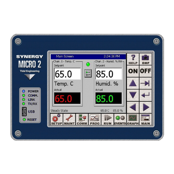
5.0 FRONT PANEL AND CONTROLS 5.1 Front Panel Layout The Synergy Controller features a color touch screen, a number of software keys and a front accessable USB Host port.. The principal components of the Synergy Controller Interface Panel are identified in the layout below. Synergy Controller–... -
Page 23: User Interface
5.2 User Interface Help Key: context sensitive help. BMP Key: take screen shots. Turn Chamber ON or OFF Select Keys: Help with entering data and selecting from lists & groups SCREEN NAVIGATION KEYS SETUP MAINT COMM PROGRAM EVENTS GRAPH MAIN The Following Folders and Screen Editors Will Appear When Pressed Calibration Machine... -
Page 24: Lcd Screen Touch Screen
5.2.1 LCD Screen Touch Screen Synergy Controller incorporates a 320 x 240 color LCD with a touch screen Windows graphical user interface. The screen shot shown below identifies the common elements of the Synergy Controller display. The title bar at the top and the status bar at the bottom of the window are found on most screens. “Alarm”... -
Page 25: Function Keys
5.2.2 Function Keys Help Key: Press the Help key and then press a location on the touch screen, a small Help window like the one shown will appear with information to assist you. Press OK to close the Help screen. Screen Capture Key: Press this key to capture a bitmap image of the current screen and store it to a USB Hard Disk. -
Page 26: Keypads
5.2.3 Keypads Synergy Controller User-Interface uses Numeric and Alpha-Numeric keypad for data entry. The screenshots below provide a few examples. Numeric Keypad Example: The number keypad at left is a typical keypad used to enter a controller parameter. Parameter Name Valid Range Present parameter value New paramter value... -
Page 27: Screen Navigation Keys
5.2.4 Screen Navigation Keys The eight keys below the LCD are the Screen Navigation Keys (Soft keys). These are labeled: SETUP, MAINT, COMM, PROGRAM, RUN, EVENTS, GRAPH, and MAIN. These keys provide easy navigation to the controller’s setup, operating and programming features. All the Synergy Controller screens retain their state so when you navigate away from a screen and return, the folder remains in the state that it as in. -
Page 28: Screen Overview
5.3 Screen Overview This section provides a single page overview of the controller’s eight screen navigation buttons and screens. For in-depth information on each screen, go to the corresponding manual section. Screen Navigation Keys: 5.3.1 Setup Screen The Setup screen is used at various times by OEMs and technicians, administrators, and engineers. The OEM and Chamber Technician will utilize a variety of Setup screens during the initial installation and calibration including: PID Settings, Calibration, Logging, Special Functions, L-Values, Chamber Setup, Resume Behavior, User Alarms, Main Screen Setup, and Event Screen. -
Page 29: Maintenance Screen
5.3.2 Maintenance Screen The Maintenance screen is generally used at by OEMs and technicians during setup and tuning and by engineers and operators during operation. The OEM and Chamber Technician will utilize the following Maintenance screens during the initial installation and calibration: Channel PIDs, File Utilities, Data and Time, and Restart Screens. -
Page 30: Comm Screen
5.3.3 Comm Screen The Communication screen is used at various times by OEMs and technicians, administrators, and engineers. The four folders in the Communication Screen are used to setup the controller’s communications ports. The RS-232 folder is read-only and displays the fixed parameters for the RS-232. The RS-485 port is used to setup the connection to the UUT Thermocouple modules. -
Page 31: Program Screen
5.3.4 Program Screen The Program screen is used at various times by OEMs and technicians, administrators, and engineers to load, save, create and edit controller programs. PROGRAM Screen ♦ Create a New File ♦ Open and Existing File ♦ Save the Loaded File ♦... -
Page 32: Run Screen
5.3.5 Run Screen The Run screen is used by engineers and operators to load, control, and monitor programs. RUN Screen ♦ Open File ♦ ♦ Run From (from a selected step) ♦ Run Off (program with outputs off) ♦ Stop ♦... -
Page 33: Events Screen
5.3.6 Events Screen The Events screen is used at various times by OEMs and technicians, engineers and operators. The OEM and Chamber Technician will utilize all of the Events screens during the chamber setup and testing. The Engineer/Operator uses the Events screen to monitor and control the user defined Event Outputs. UUT Temperatures folder is used to display up to 64 T-Type Thermocouple from the UUT Thermocouple monitoring system. -
Page 34: Graph Screen
5.3.7 Graph Screen The Graph screen is used at various times by all users; i.e. OEMs and technicians, engineers and operators to monitor the operation of the equipment. The Graph scaling, X and Y can be adjusted in the SETUP\Graph Settings folder. GRAPH Screen Screen Information: ♦... -
Page 35: Main Screen
5.3.8 Main Screen The Main screen is used at various times by all users. The Main screen provide an On/Off push button and LED and Setpoint for Steady State operation. The Main screen can be adjusted to display a Chamber Light Switch or Event Switch, up to 10 Sensor values, a process graph, and various control channel arrangements from the SETP\Main Screen Setup Folder. - Page 36 Key Pad Screen Alphanumeric data is entered in the Synergy Controller with the T9 Key Pad. When Alpha is selected, pressing a key will cycle through the letters on that key. For example, if the first key pressed is “2” the text box displays the letter “A”.
-
Page 37: Setup Screen
6.0 SETUP SCREEN The SETUP screen provides access to all of the controller setup parameters. The Setup screen is organized into 14 folders as follows: 6.1 Setup Folder Root Menu Setup Screen • Calibration • PID Settings • Special Functions •... -
Page 38: Calibration
6.2 Calibration The SETUP\Calibration\ screen provides access to Setup and calibration parameters. This screen is organized into 5 folders as follows: Setup\Calibration Folder • Calibration Channel n • Altitude • Guaranteed Soak • Input • Virtual Sensors 6.2.1 Channel Calibration The SETUP\Calibration\Calibration Channel n\ Screen contains all of the setup and calibration parameters for channel n. - Page 39 SETUP\Calibration\Calibration Parameter Description CH1 Sensor Select Channel Sensor Select Select the channel feedback Sensor Temperature Offset (b) Channel Offset and Gain (Span) Temperature Gain %(m) Adjust the Channel Offset (b) and Gain %(m) to accommodate channel specific sensor errors such as those caused by the sensor placement.
- Page 40 6.2.1.1 Channel Sensor Selection The SETUP\Calibration\Calibration Channel n\Channel n Sensor Select parameter determines the sensor for channel n. The sensor is selected from the Sensor Selection screen as follows: 1. Select the Module from the list in the first column. 2.
-
Page 41: Altitude Value
6.2.2 Altitude Value SETUP\Calibration\Altitude\Altitude Value\ SETUP\Calibration\Altitude\Altitude Value\ sets the scaling for the pressure channel. Set the altitude value to 0 for linear scaling for regular pressure transducers. For Granville-Philips transducers, set the parameter to 10, 11 or 12 for exponential scaling. A Registration Key may be required to access this feature. See additional details in the Altitude/Space Chamber Setup section. - Page 42 SETUP\Calibration\ Input\High Res\RTD n\Gain\ HIGHn_GAIN SETUP\Calibration\ Input\High Res\RTD n\Offset\ HIGHn_OFF This screen is used to enter an Offset and Gain (span) for the raw data in Ohms. This is used to compensate for a difference in the reading due to sensor position, wiring, etc. Use the Two Point calibration calculation formula section 16 to calculate the Offset and Gain (span).
- Page 43 Vaisala HMM30C Temperature Compensation Vaisala Relative Humidity sensors are available in temperature compensated and uncompensated versions (HMM30C) and the Synergy Controller is compatible with both types. In addition the controller can accommodate sensors with 0-5VDC and 4-20mA outputs. The Synergy Controller uses the Vaisala recommended temperature compensation algorithm for the HMM30C.
-
Page 44: Virtual Sensors
6.2.5 Virtual Sensors The Synergy Controller supports a variety of Virtual Sensor for a variety of applications. The virtual accepts on or more sensors and calculates a new sensor value. Virtual Sensors • Wet Bulb-Dry Bulb • Virtuall Kft • Virtual Pressure 6.2.5.1 Wet Bulb/Dry Bulb Virtual Sensor The Virtual Wet Bulb/Dry Bulb sensor measures relative humidity using two temperature sensors as an... - Page 45 SETUP\Calibration\Virtual Sensors\Wet Bulb Dry Bulb\Wet Bulb Sensor WETB_SENID SETUP\Calibration\Virtual Sensors\Wet Bulb Dry Bulb\Dry Bulb Sensor DRYB_SENID Assign the sensor IDs for the two temperature sensors. SETUP\Calibration\Virtual Sensors\Wet Bulb Dry Bulb\Altitude – Torr\ WBDB_ALT The Altitude – Torr Sensor parameters sets the pressure at the site to allow the controller to compensate the humidity calculation for the pressure altitude.
- Page 46 These settings specify the two sensor IDs and control when the virtual sensor switches between the two input sensors. (The transfer pressure threshold and hysteresis which) SETUP\Calibration\Virtual Sensors\Virtual Pressure\Std. Range Pres. Sensor ID. VP_STDALT_SENID SETUP\Calibration\Virtual Sensors\Virtual Pressure\High Alt. Pres. Sensor ID. VP_HIALT_SENID SETUP\Calibration\Virtual Sensors\Virtual Pressure\Transfer Pres.
-
Page 47: Pid Settings
6.3 PID Settings The Synergy Controller implements the Proportional, Integral, and Derivative (PID) algorithm for each control channel. The Synergy Controller PID algorithms are designed to automatically adjust the output variables to hold the process variable at the setpoint while minimizing instability and error. The PID Settings screen is used to edit the constants that control the PID algorithms. -
Page 48: Cascade Control
Cascade feature. Register Cascade The Cascade control feature requires a Registration Key. Contact Tidal Engineering for the Cascade Registration Key for your controller. Tap in the Registration Key field to open the number pad. Enter the Registration Key and tap the Register button. - Page 49 Register Cascade The Cascade control feature requires a Registration Key. Contact Tidal Engineering for the Cascade Registration Key for your controller. Tap in the Registration Key field to open the number pad. Enter the Registration Key and tap the Register button.
-
Page 50: Special Functions
6.4 Special Functions Special Functions The Cascade parameters are organized in the following three folders: ♦ Celsius/Fahrenheit ♦ 12/24 Hour Time ♦ Output 11 Control Type ♦ Output 17 Control Type ♦ Output 18 Control Type ♦ Analog Retransmits ♦ PWM Retransmits ♦... - Page 51 On/Off mode. You can monitor the Ambient Coil from the Events\Digital Outputs folder. The LED is gray when off, red when on and yellow when in time proportioning mode. Output 17 Control Type (Vacuum or Purge) The Output 17 Control Type selects the type of control logic for Vacuum/Purge output. When channel 2 is Altitude, choose either the Vacuum mode or Purge mode.
- Page 52 Analog Retransmit 1 and 2 One of the optional features often specified with environmental chambers is the circular chart recorder. The chart recorder is a graphing device used to record chamber data such as temperature, humidity and pressure over time. An example of a Tenney Chamber with a circular chart recorder is shown below. Note that the Synergy Controller includes built in Logging features that can often eliminate the need for a conventional chart recorder.
- Page 53 PWMs Retransmits PWM Retransmit Folder The PWM Retransmit feature is similar to the Analog Retransmit except the output is modulated by varying the Pulse Width, thus the term Pulse Width Modulation. This is also known as Time- Proportioning. To configure the outputs, press the SETUP button on the Synergy Controller touch screen and go to the SETUP\Special Functions\PWM Retransmits.
- Page 54 Remote Start/Stop The Remote Start/Stop Parameters: ♦ Remote Start/Stop Enable ♦ Start Input ♦ Stop Input The Remote Start/Stop inputs can be connected to remote switches and used to turn the controller On and Off remotely. Analog Programming The Analog Programming Feature parameters are: ♦...
-
Page 55: Settings List
6.5 Settings List Description Command Value Calibration Channel 1 Ch1 Calibration CAL1 Ch1 Alarm Low Limit Ch1 Alarm High Limit Channel 2 Ch2 Calibration CAL2 Ch2 Alarm Low Limit Ch2 Alarm High Limit Altitude Guaranteed Soak PID Values Channel 1 Proportional Band, Ch1 Heating PB1H Reset, Ch1 Heating... - Page 56 Description Command Value Special Functions Celsius / Fahrenheit Output 11 Control Type OT11 Output 17 Control Type OT17 Output 18 Control Type OT18 Ch1 Low Range Ch1 High Range Ch2 Low Range Ch2 High Range Ch 1 RTD Type Vaisala Compensation Enabled VCMP Analog Retransmit 1 OUT_420_1...
-
Page 57: L - Values
6.6 L – Values The L-Value parameters control the operation of the chamber outputs. L_Values The Cascade parameters are organized in the following three folders: Thermal Shock Chamber Parameters 1L1 Ch1 Main Cooling Turn-On 1L2 Ch1 Main Cooling Turn-Off 1L3 Ch1 Setpoint Transfer Setting 1CTY Ch1 Chamber Type 2L1 Ch2 Main Cooling Turn-On 2L2 Ch2 Main Cooling Turn-Off... - Page 58 L-Value Descriptions L-Values are parameters for the programmable logic that control processes in the Device Primitives. Flow charts illustrating the Device Primitives are illustrated in Section 6.7 Device Primitives of this manual. Please refer to the Device Primitives flow charts in conjunction with the definitions below when editing L-Values. Thermal Shock Parameters 1L1 Ch1 Main Cooling Turn-On Cooling output required to turn on channel 1 cooling.
- Page 59 L11 Dehumidify / Vent On Percent dehumidify required to enable dehumidify device. (0 to 100%) L12 Dehumidify / Vent Off Percent humidify required to turn off dehumidify device. (0 to 100%) L14 Time Delay Boost Cool Time delay required before Boost Cool is enabled. (0 to 1200 seconds) L15 Compressor Turn-Off Delay Delay required before turning off a compressor.
-
Page 60: Logging
6.7 Logging The Synergy Controller’s logging system periodically captures and stores user selected data at a user specified interval to the Storage Card, the on board non-volatile Flash memory. In addition the logging system also records alarm activity and other abnormal events to the Storage Card. The log data (sometimes called history) can be exported to removable memory for use in test documentation. - Page 61 The screen at the left appears. The following data is available for logging. ♦ Channel Readings (Actual) ♦ Channel Setpoints ♦ Channel PIDs ♦ Machine Values ♦ UUT Values Synergy Controller Technical Manual, Revision H Page 61...
- Page 62 Example Log Printout: Date and Time, CH1Actual, CH2Actual, CH1Setpoint, CH2Setpoint 02/23/2001 11:33:56, 24.9, 48.0, 25.0 50.0 02/23/2001 11:34:56, 24.9, 50.0, 25.0 50.0 02/23/2001 11:35:56, 25.0, 51.8, 25.0 50.0 Step #2: Select the Channel Readings Folder Use this screen to select the process values for each selected channel for logging.
- Page 63 Step #5: Select the Machine Values Folder Select the Machine Input process values of Sensors 1 thru 8 for logging. These inputs usually consist of compressor suction and discharge pressures and temperatures. These values can be viewed in real-time from the Low Res.
- Page 64 Export Log to USB The export process is monitored in the Export History Status window. First the Synergy Controller prompts for a USB Hard Disk. If your removable storage media is not installed, install it and press the OK button. Once the media is detected the Synergy Controller will automatically export the file.
- Page 65 Synergy Controller Data Logging Capacity Calculations As described above, the Synergy Controller records process data, setpoints and machine diagnostics to its Storage Card. This information can be exported at a later time to a USB Hard Disk or to the FTP server and used in a test report or for system troubleshooting as explained in the previous section.
- Page 66 Log Data Size Data Max. Size Description CH1 Actual 6 bytes Temperature CH2 Actual 6 bytes Humidity CH3 Actual 6 bytes Pressure CH1 Setpoint 6 bytes Temperature CH2 Setpoint 6 bytes Humidity CH3 Setpoint 6 bytes Pressure CH1 Heat PID 4 bytes 0 to 100% CH2 Heat PID...
-
Page 67: Chamber Setup
6.8 Chamber Setup The Chamber Setup Directory is used for factory setup. The chamber type specified in the Synergy Controller must match the chamber that it is controlling. The Chamber Type setting maps software outputs to chamber hardware. Each chamber type has as specific map that is unique to that type of chamber. The operator should NEVER change this setting. - Page 68 Switching Module Configuration The Olympic board drives all of the outputs for the chamber thru solid state switches called Switching Modules (SM). In some cases there is more than one way to connect a specific output. This provides flexibility when wiring the chamber to support new and retrofit installations.
-
Page 69: Graph Settings
6.9 Graph Settings The Graph Settings Paramters Control both the chart on the Graph Screen as well as the chart on the Main Screen. 6.10 LCD Settings The LCD Brightness feature changes the brightness of the LCD touch screen. If your Synergy Controller is at eye level or you work in very light conditions such as a room with direct sunlight, you may want to set the LCD screen to a slightly darker setting. - Page 70 Navigation and Touchscreen Control Screen Selection Screen Screen usage summary Default Access SETUP Chamber Configuration, Settings and PID values Administrator MAINT Time/Date, Monitoring Maintenance COMM Communications setup, Network Setup Engineer PROG Program creation and editing Engineer Program Run Operator EVENTS Input and Output Monitor and User Event control Operator GRAPH...
- Page 71 Synergy Controller Technical Manual, Revision H Page 71...
- Page 72 In the \Panel Lock\ folder there are two subfolders; Admin Settings and Screen Settings as shown below. The \Panel Lock\Admin Settings\ folder is used to enable the Panel Lock feature and control Panel Lock options and passwords. The panel lock options control the function of Panel Lock in two ways: 1.
- Page 73 The Panel Lock Passwords are listed in the \Panel Lock\Admin Settings\ folder in the order of access privilege. The Administrator password has the highest privilege and can access all the controller screens. The password can be up to 10 alpha-numeric characters. To change the password, select the user level and press the Change button to open the T-9 pad, and then enter the new password.
- Page 74 The \Panel Lock\Screen Settings\ folder is used to assign the user level for each screen. The suggested user levels are listed in the table below. Default User Levels Screen Default Access SETUP Administrator MAINT Maintainer COMM Engineer PROG Engineer Operator EVENTS Operator GRAPH...
-
Page 75: Languages
The user can go to the \Panel Lock\Admin Setup\ folder to clear the password without waiting for the Unlock Duration inactivity timer to expire by unlocking and re-locking the panel. 6.12 Languages The Synergy Controller can be configurable to many language formats. Please contact Tidal Engineering for more information. Note: The Espanol setting is for demo purposes only. - Page 76 There are 102 inputs/variables that can be monitored for user alarm conditions (see the table below) The Input options are: Module First Selection Second Sel. Choices Olympic Board RTD1&2, Analog 1-4 UUT Module Inputs UUT Module Sensor Machine Inputs Low Resolution Channels 1 thru 8 Digital Inputs Inputs 1 thru 16 Channels...
- Page 77 Open the Setup Screen and browse to the User Alarms folder Select the Sensor, Setpoint or channel. Define the comparison type and the scaling, The Comparison choices are: 1. Input Open. 2. Input Closed. 3. Greater than. > 4. Less than. > The Data Scaling choices are: 1.
- Page 78 Select the Alarm Threshold. This step is not required for Digital Inputs. Enter a name for the alarm. This name appears in the alarm screen when the alarm occurs and in the alarm list. Select the desired alarm response. The Options are : 1.
- Page 79 Confirm your choices and finish. User Alarm Example 1: Create an alarm that senses Digital Input 5 and Displays “Oxygen Sensor Warning” when the input is Open. Oxygen Oxygen Sensor Sensor Warning Warning Alarm State Normal State Open the User Alarm folder and press the Add Alarm button on the Setup screen shown at left.
- Page 80 Press the Sensor text box as shown at left to start the Sensor Selection process. Select Digital Input 5 as shown in the figure at left and then press accept. The wizard displays the code for this sensor. Press Next -> to continue. Synergy Controller Technical Manual, Revision H Page 80...
- Page 81 Select the Comparison from the drop down window. In this case Input Open. Note: Data Scaling doesn’t apply for digital inputs Then press Next ->. Enter a name for this alarm. Press the text box to open the Alpha Numeric Keypad.
- Page 82 Then press Next ->. Select the Alarm Actions. In this case, the “Show Alarm” and “Log Alarm” options are selected. Then press Next ->. Confirm your choices and press Finish to complete the Alarm entry process. Synergy Controller Technical Manual, Revision H Page 82...
- Page 83 The User Alarm Setup screen shows the new entry. In operation, the Alarm Screen in the Maintenance folder indicates a normal state when the Input is closed as shown in the figures below: The Alarm Screen in the Maintenance folder Indicates the alarm condition when the Input is open as shown in the figure below: Synergy Controller Technical Manual, Revision H Page 83...
- Page 84 User alarms in the Maintenance/Alarm screen are cleared and acknowledged like built-in High and Low limit alarms. The alarm entry indicates Yes in the Ack column after an alarm is acknowledged. The alarm indicates Yes in the Cleared column after it has been cleared, i.e. the alarm condition is no longer present. As with built-in alarms, user alarms can be acknowledged before or after they have cleared but the alarm is removed from the list only after the alarm condition has cleared and it has been acknowledged by the operator.
- Page 85 For example, in the screenshot below, the Alarm has been acknowledged but the alarm condition still exists. Once the Alarm has been acknowledged and the alarm condition has cleared the alarm entry is removed from the list as shown below. Synergy Controller Technical Manual, Revision H Page 85...
- Page 86 Example 2 At low atmospheric pressures, the heaters in most altitude chambers are turned off so they don’t overheat when convection cooling capacity is reduced. In this example we will create an alarm that senses Hi Res Input 3 (Torr) and opens Relay 2 when the value is less than 30 Torr. This alarm is named “Heater Safety Shutoff”...
- Page 87 Less Then comparison type. We also select the Scaled Value for Data scaling because we want to check the scaled Torr value as opposed to the Raw 0-5 Volt input value. Then we press Next-> to continue. Next we enter the Alarm Threshold. Press the Alarm Threshold text box to open the number pad.
- Page 88 Confirm the Alarm Threshold. Then we press Next-> to continue. Here we enter the Alarm response. In this case we only want to Activate Relay 2. Then we press Next-> to continue. And finally, we confirm our settings and then press Finish.
- Page 89 The User Alarm Setup screen lists our new alarm as shown at left. In operation, when the Torr value is greater than 30 Torr, as shown here, Relay 2 (Event 24) is Activated (Grey). When the Torr value is less than 30 Torr, as shown here, Relay 2 (Event 24) is normal (Red).
-
Page 90: Resume Behavior
6.14 Resume Behavior The Resume Behavior parameters control the behavior after the controller power is restored. Steady State parameter controls the behavior when the controller power is lost while the controller is on and in Steady State mode. Profiles parameter controls the behavior when the controller power is lost while the controller is running a Program. - Page 91 Large, Medium, Small Channel Text sizes Large Display Channel Text Medium Display Channel Text Small Display Channel Text Small Display Channel Text with Graph Synergy Controller Technical Manual, Revision H Page 91...
-
Page 92: Sensor Displays
6.15.2 Sensor Displays Up to 8 Sensors Medium Display Channel Text Sensor 6 Sensor 7 Sensor 3 Sensor 8 Sensor 4 Sensor 9 Sensor 5 Sensor 10 Synergy Controller Technical Manual, Revision H Page 92... -
Page 93: Chamber Light
6.15.3 Chamber Light Main Screen Setup Folder Chamber Light Folder Chamber Light with Large Display Text Chamber Light with Medium Display Text Synergy Controller Technical Manual, Revision H Page 93... -
Page 94: Event Screen Setup
6.16 Event Screen Setup Event Screen parameters that pertain to Humidity control features can be hidden, allowing Event 7, Event 8, and Event 9 to be displayed. The Event Screen can be customized to display user-friendly names rather than just the Event number. -
Page 95: Maint Screen
7.0 MAINT SCREEN 7.1 Operator Interface The Maintenance Directory provides a set of utilities used during the operation and maintenance of the chamber. Maintenance Screen Press the MAINT button to access the following functions. ♦ Alarms (View and Clear Alarms) ♦... -
Page 96: Alarm Functions
7.2 Alarm Functions This section contains information on: Low Storage Alarms, Low Memory Alarms and Alarm Actions (Relays, Alarm Indications, and Outputs). Note: Alarm Relays are normally energized. SYNERGY CONTROLLER ALARMS AND ACTIONS ALARM RESPONSES Alarm Alarm Alarm On All Outputs Alarm Name Relay 1 Relay 2... - Page 97 Synergy Controller Low Program Memory & Low Storage Alarms There are two types of local storage on the Synergy Controller: Storage Card (Flash) and RAM. The Storage Card holds all the application programs, programs, and log files. RAM is used exclusively by the Operating System (OS) and Synergy Controller software.
- Page 98 Select Export History if you would like to save the history file. This step can be skipped if you don’t need the data in the log file. See Section 7.1 Maintenance: Operator Interface for more information on exporting history files. WARNING: Once deleted, logging data cannot be recovered.
- Page 99 Select Clear Log and press the Execute. WARNING: Once deleted, logging data cannot be recovered. The chamber should now be free of the Low Storage alarm condition Acknowledge the Low Storage Alarm Condition. Once you have cleared the alarm condition, you can acknowledge the alarm to remove it from the Alarms folder list.
- Page 100 Preventing the Low Storage Alarm condition You can eliminate the recurrence of a Low Storage Alarm Condition by adjusting the Log File Size to a value less than the space available on the Synergy Controller Storage Card. Follow the steps below: Go to the Setup screen and select the Logging\Setup folder.
-
Page 101: Channel Pids
7.3 Channel PIDs The Channel PIDs screen shows a third column when cascade mode is enabled for the channel. All columns show values for the following parameters: Pn, In, Dn, PID, Err, Setpoint, Actual, P.B., Reset and Rate. The Setpoint and Actual numbers in the cascade column are the desired setpoint, and actual temperature of the product inside the chamber. -
Page 102: About Screen
Tidal Engineering for software upgrades. The Help Version refers to the context sensitive help available from the touch panel. The Operating System frame contains Tidal Engineering’s part number, build date and version number of the Windows Embedded Compact operating system running on the controller. -
Page 103: Software Upgrade Procedures
7.5.1 Software Upgrade Procedures The Synergy Micro 2 upgrade is delivered in a compressed format and is installed using a USB Flash Disk. The delivered file name contains the Version and Build number. For example: SYNERGY_MICRO_2_VERSION_3_0_7_Build_893u is version 3.0.7 Build 893u. The Synergy Controller Configuration Backup and Restore features should be used to backup settings before performing the upgrade. - Page 104 Then select either the Storage Card or the USB Hard Disk from the Drive List and. Then press the File: Text Box Enter the File Name using the T9 Pad. Then press OK. Confirm the file name that appears in the Backup File text box and then press Backup.
- Page 105 The controller will confirm that the settings were backed up successfully as shown at the left. Acknowledge the window by pressing OK. Step 2. Install the New Software Copy the zip file to a temporary directory on your PC. Place a USB Flash Disk key in the USB port on your PC. Double click the zip file (note that your screen may look different than the screen below if you have a different zip program installed on your PC) Synergy Controller Technical Manual, Revision H...
- Page 106 Synergy Controller Technical Manual, Revision H Page 106...
- Page 107 Select Extract Files and browse to the USB Flash Disk on your PC as shown below. In this example the drive is named “Removable Disk (F:)” After the files are extracted you will see the Upgrade directory on your USB key as shown below.
- Page 108 Place the USB Flash disk in the Synergy Micro’s USB port and browse to the Maintenance Screen. Open the File Utilities Folder and press the Upgrade Software folder. Make sure the USB Flash Disk is in the Controller's USB port and press the Upgrade Software button.
- Page 109 Press the OK box and restart the controller. Go to the Maintenance Screen and open the About folder to verify the appropriate Version number as shown at left. Step 3. Configure the Controller When the chamber restarts, the controller may indicate that the current chamber type differs from the last chamber type.
- Page 110 Then press Accept. Next, Reset the Controller or Cycle power. When the chamber restarts, the controller will indicate that the current chamber type differs from the last chamber type. This is OK. Press OK to acknowledge that message. You will then be asked if you would like to discard the old settings and load the current settings.
- Page 111 Then select either the Storage Card or the USB Hard Disk from the Drive List. Then select the appropriate file from the list and press Select. Confirm the File Name that appears in the Restore File text box and then press Restore. The Controller will confirm that the settings were restored.
- Page 112 Synergy Controller Setting List Description Command Value Chamber Configuration Registration Keys (optional) Web Server Registration Key Cascade Registration Key Pressure Registration Key Note: These alphanumeric keys were provided if you purchased these features. If you do not have them, they are available from your service representative.
- Page 113 Synergy Controller Settings List Description Command Value Calibration Channel 1 Ch1 Calibration CAL1 Ch1 Alarm Low Limit Ch1 Alarm High Limit Channel 2 Ch2 Calibration CAL2 Ch2 Alarm Low Limit Ch2 Alarm High Limit Altitude Guaranteed Soak PID Values Channel 1 Proportional Band, Ch1 Heating PB1H Reset, Ch1 Heating RS1H...
- Page 114 Synergy Controller Setting List - Continued Description Command Value PID Values (cont) Cascade CAS1_ENABLE Cascade CH1 Enabled Channel 1 Cascade Sensor CSS1 CH 1 Cascade High Limit C1HL CH 1 Cascade Low Limit C1LL CH1 Cascade Prop. Band CPB1H CH1 Cascade Reset CRS1H CH1 Cascade Rate CRT1H...
- Page 115 Synergy Controller Settings List - Continued Description Command Value Special Functions Celsius / Fahrenheit Output 11 Control Type OT11 Output 17 Control Type OT17 Output 18 Control Type OT18 Ch1 Low Range Ch1 High Range Ch2 Low Range Ch2 High Range Ch 1 RTD Type Vaisala Compensation Enabled VCMP...
-
Page 116: Export Screenshots
7.5.2 Export Screenshots Select the Export Screenshots folder. Tap Browse. Select the USB Flash Disk and tap Export. 7.5.3 Logging See Logging features in Section 6.0 Setup. Synergy Controller Technical Manual, Revision H Page 116... -
Page 117: Date And Time
7.6 Date and Time Date and Time Adjust the date and time and press the Apply button. 7.7 Restart Restart Controller It is necessary to restart the controller during some chamber setup procedures. This can be done by cycling power to the controller or by using the Restart button in the Maintenance screen as shown on the left. -
Page 118: Comm Screen
The RS–232 port may be used with third party test and measurement software such as LabVIEW, Tidal Engineering’s Synergy Manager or Tidal Engineering’s SimpleComm. The Synergy Manager PC based monitor and control software and SimpleComm are discussed in Section 17.4... -
Page 119: 119
8.4 IEEE 488 / GPIB IEEE 488/ GPIB The IEEE 488 port may be used with third party test and measurement software such as LabVIEW, Tidal Engineering’s Synergy Manager or Tidal Engineering’s SimpleComm. 8.5 Ethernet Network Ethernet Network The Ethernet Network interface support s a number of powerful communications tools. -
Page 120: Ethernet\Ip Settings
8.5.1 Ethernet\IP Settings Ethernet These Ethernet settings are used to connect to the chamber over your local network LAN, or the Internet. Set the IP Address Selection to DHCP if your network uses a DHCP server to dynamically assign IP Addresses. If your network does not have a DHCP server or you want to manually set the IP Address of your controller, set the IP Address Selection setting to Static IP. -
Page 121: Tcp/Ip Server
E‐Mail is supported on the software application Version 3.0.7 Build 893B and newer. Contact the Tidal Engineering if you are interested in a software upgrade. This Synergy Controller application note Describes these e‐mail features and provides instructions and examples for setup. -
Page 122: Ethernet Network\E-Mail\Addresses
8.5.5.2 Ethernet Network\E-Mail\Addresses E-Mail Enter up to five E-Mail addresses or Cell Phone numbers as shown on the left. 8.5.6 Printer Setup Printer Setup Setup the Network Printer parameter as shown on the left according to y our printer. See Application note 84 Application Note 84 Synergy Controller Technical Manual, Revision H Page 122... - Page 123 Synergy Controller Technical Manual, Revision H Page 123...
- Page 124 Configuring Internet Explorer The web server works seamlessly with Microsoft Internet Explorer version 5.0 and higher. You must, however, adjust the default settings in Internet Explorer. Open Internet Explorer and from the Tools menu, select Internet Options. Press the Settings... button under Temporary Internet Files. In the Settings screen, select the “Every visit to the page”...
- Page 125 Accessing the Synergy Controller via the Web To access the controller via the web, open Internet Explorer and type your controller’s IP address in the address bar. You can find the controller’s IP address in the Web Server folder under the COMM button. For example, if the Web Server Address on the controller is 170.23.10.10 then type “170.23.10.10”...
-
Page 126: Prog Screen
9.0 PROG SCREEN The Synergy Controller provides a powerful and easy to use program editor for creating sophisticated multi- channel profiles of Temperature, Humidity, Altitude, etc. versus time. These programs, also known as profiles or recipes, are created from the Program Screen. Program Screen The Program Screen provides seven simple function buttons and displays a listing of the... -
Page 127: Creating A New Program
♦ Drop down the Drive List to select the drive as shown at left. Note: The FlashDisk is the Processor’s internal Flash memory. The Storage Card is the Synergy Controller’s SD Flash memory. ♦ Select the desired file from the File List that appears. - Page 128 3. Select Step Type 4. Temperature Control 4. Enter Temperature Setpoint & Press Accept 5. Humidity Control 6. Enter Humidity Setpoint and Press Accept 7. Specify a Ramp Time or Jump to Setpoint Synergy Controller Technical Manual, Revision H Page 128...
- Page 129 8. Enter Ramp Time 9. Turn On / Off Events & External Outputs 10. Finish 11. View Completed Step. Synergy Controller Technical Manual, Revision H Page 129...
-
Page 130: Step Type Descriptions
After pressing the Finish button, the program screen displays your new step. Verify your entry and continue adding, inserting, or copying steps as necessary to complete your program. Press the Save File button when you are through creating your program. Notes Step 3 Note: You may want a Stop step at the end of your program. - Page 131 Synergy Manager can be used to create profiles for the Synergy Controller on your PC where they can be viewed graphically, stored and archived. Synergy Manager is Tidal Engineering’s PC application designed to program, monitor and control multiple environmental test chambers. Synergy Manager can save profiles in the Synergy Controller VPL format so they can be copied to and then run on the controller.
-
Page 132: Synergy Controller Program Sheet
9.4 Synergy Controller Program Sheet FILE # For Chamber Types: Temp.-only, Temp. / Humidity, Temp. / Temp., & Temp. / Pressure Setpoint(s) Time Events Jump Hum. / Loop WAITFOR AUTOSTART Temp. / X = ON Temp Press. Time Stop Type 1 2 3 4 5 6 Temp Hrs: Min: Sec... -
Page 133: Copying, Editing And Deleting A Step
9.5 Copying, Editing and Deleting a Step To Copy, edit or delete a step, press the appropriate button at the top of the Program screen. The Edit Step Wizard will guide the user through each of these functions ♦ Copy Step: Select the step you wish to copy. The Wizard will ask whether you wish to copy this step at the end of the program or insert the copy somewhere within the program. -
Page 134: Run Screen
10.0 RUN SCREEN Press the RUN Screen button to open the Run screen. From the Run screen you can, Start, Stop and Pause a program. If a file is loaded, it will appear in the Program screen will appear in the Run screen when the Run screen is opened. - Page 135 Dynamic Edit To dynamically edit a Jump Loop the program must be running and currently within the target loop. Press the Pause button to pause the program. Highlight the desired Jump Loop step then press the Dyn. Edit button. Press the Jump Loops Remaining text box to open a numeric keypad and enter the new number of jump loops to perform and press OK.
-
Page 136: Events Screen
11.0 EVENTS SCREEN The Events Screen provides access to the controller’s Inputs and Outputs. Events Screen The Events Screen contains the folders for six Event status folders including the Event Output folder. These folders are as follows: ♦ Events Outputs ♦... -
Page 137: Event Outputs Setup
11.1.1 Event Outputs Setup Event Screen Setup The Event Screen Setup Folder is used to configure the Event Outputs Screen as follows: 1. Display Humidity Channel Event Outputs 2. Assign User friendly Event names to each Event Output. See Section 6 for more details. -
Page 138: Event Output Board Options
11.1.3 Event Output Board Options Tidal Engineering offers two types of event output boards: standard AC output (TE1151-6), and relay output (TE1708-6). Each of these connects to the Olympic board or to the 2SM board with a 20 position ribbon cable. -
Page 139: Event Output Board Connections
11.1.4 Event Output Board Connections The event board connects interchangeably to either of two Synergy outputs, the 20-pin P6 connector on the Olympic board or alternatively to the J5 connector on the 1SM 12 channel output board. To connect the event board directly to the Synergy Controller: 1. - Page 140 Synergy Controller Event Setup Instructions There are several ways to control the events on the Synergy Controller. You can control them locally through the touch panel, through remote software such as the Synergy Manager software or within a chamber profile. The instructions that follow describe how to test the event output board by operating the Synergy Controller locally) from the touch screen) in Manual Mode.
- Page 141 TE1151-6 Triac Output Board Schematic Synergy Controller Technical Manual, Revision H Page 141...
- Page 142 TE1708-6 Relay Board Schematic Synergy Controller Technical Manual, Revision H Page 142...
-
Page 143: Uut Temperatures
11.2 UUT Temperatures The UUT Module (Unit-Under-Test) is a 16-channel thermocouple data acquisition unit. Developed to expand the input capabilities of the Synergy Controller, the UUT module captures and logs data from the test. Up to four modules can be attached to the Synergy Controller for a total of 64 thermocouple inputs. The UUT data can optionally be logged and the log file may be used for analysis, graphing and reporting. -
Page 144: Digital Inputs
Information on the Selected Output is displayed in the text box at the bottom of the screen. Highlight an item (Fan, HiAl, PIDH…) by pressing the output label and view the selected output properties below: for example “1: B12a, Out 1, On/Off, On” The output information is displayed in the following format: “A1 : A2, A3, A4, A5”... -
Page 145: High Resolution Analog Inputs
11.5 High Resolution Analog Inputs High Resolution Analog Inputs ♦ RTD 1 ♦ RTD 2 ♦ Analog 1 (Volts) ♦ Analog 2 (Volts) ♦ Analog 3 (Volts) ♦ Analog 4 (Volts) High Resolution Analog input Screen monitors the signals from process sensors or machine monitors. The Synergy Controller displays both the Raw Reading (Volts) and the Scaled value. -
Page 146: Graph Screen
12.0 GRAPH SCREEN Graph Screen Touch the screen to adjust the graph settings. Line colors are defined in the screen below. The settings for the Graph can be changed from the Graph Settings folder in the Setup Screen. 12.1 Temperature / Humidity / Air Temperature Graph Options Select the individual checkboxes to display specified graph lines. -
Page 147: Main Screen
13.0 MAIN SCREEN The Synergy Controller can run complex programs as described in the previous sections. In addition, it can also operate at steady state conditions, i.e. manual operation. This section explains the screens and procedures that are used to quickly setup and run your chamber at steady state conditions. The Main screen can be customized in a variety of ways. -
Page 148: Turn The Chamber On
13.1.2 Turn the chamber On Press the MAIN Navigation Screen button. ♦ Press the on/off button to toggle the chamber state. The current state of the chamber is indicated by the LED indicator above the on/off button. Gray indicates that the chamber is Off. Green indicates that the chamber is On 13.2 Main Screen Setup •... -
Page 149: Chamber Light
13.2.2 Chamber Light The chamber light can be assigned to an Event output and displayed on the MAIN screen as shown below. Tapping the Chamber Light Icon will change the state of the Event. 13.2.3 Channel Text Three Channel text size options are available for the MAIN screen as shown below. Large Display Channel Text Medium Display Channel Text Small Display Channel Text... -
Page 150: Sensor Displays
13.2.3 Sensor Displays Additional sensor values can be displayed on the Main screen for UUT test and other variables. Up to 8 Sensor Displays can be shown on the Main screen as shown below: Up to 8 Sensors Medium Display Channel Text Sensor 6 Sensor 7 Sensor 3... -
Page 151: Data Acquisition And Logging
14.0 DATA ACQUISITION AND LOGGING The Synergy Controller combines the functions of a chamber controller and a data logger. The Synergy Controller’s built in data logger is key to many powerful features. This section explains the Synergy Controller’s Logging system features and applications. Synergy Controllers capture a variety of data and “Deliver”... - Page 152 \Logging\Setup Folder Parameters Enable Logging Enables and Disables logger. Note that the logger will always capture message records even if logging is Disabled. For example: alarms, profile start/stop, etc. Logging Interval (Sec) this parameter sets the interval between log entries in seconds. Log File Size (MB) Maximum log file size.
- Page 153 \Logging\Profiles Log Each Profile This parameter enables profile logging. Enable this parameter to log individual profiles so they can be delivered thru the network; i.e. via e-mail, to network printers, to the Synergy and FTP Servers, as well as via download from the front mounted USB port with a USB flash drive.
-
Page 154: Deliver Test Results" Automatic Test Data Delivery
14.1.1 “Deliver Test Results” Automatic Test Data Delivery See Appendix 19 for more information \Logging\Profiles\Deliver Test Results The controller can be set to automatically deliver test results in chart (plot) and Log format thru the network as follows: Deliver Test Log to e-mail Deliver Test Plot to Printer Deliver Plot to e-mail Deliver Test Log to Synergy Server... - Page 155 Open the \Logging\Data Folder in the Setup Screen and adjust the Enable/Disable value for all the data parameters. The controllers Channel Readings (PV) and Set Points (SP) can be enabled individually as required. The Channel Deviation Limits and Cascade Control variables for each channel can be enabled as required. The Deviation Limits provide a visual reference for the test specification limits.
- Page 156 UUT Thermocouple sensors (up to 64) and the High Resolution Analog inputs can be logged. Low Resolution Analog inputs on the full sized controllers which are typically used to monitor compressor pressures can be logged. Digital Inputs and PWM outputs can be logged. Synergy Controller Technical Manual, Revision H Page 156...
- Page 157 Logging Actions The Logging Actions screen lists the test results stored on the controller and provides a set of actions that can be performed on them: Logging Status The Logging Status screen provides information about the History Log file (continuous) and the current profile log if there is one.
-
Page 158: Profile Logging
14.1.2 Profile Logging As described earlier, one of the significant Synergy Controller logging system features introduced in version 3.0.x is “Profile Logging”; i.e. the ability to log each test separately and create a uniquely identifiable test results file. Many of the latest Synergy Controller innovations utilize this capability. These features include: •... -
Page 159: Logging Commands
14.1.3 Logging Commands The logging system can be setup from the touch screen as described in the previous Logging Setup section of this application note. In addition, the logging system can also be setup and adjusted remotely, or with command file (.CFG), or a Bar Code Macro file. The command syntax for the Logging system is as follows: Command Function Example... -
Page 160: Logging Applications
14.2 Logging Applications The Synergy Controller/Logger captures and delivers test data for test reports. In addition, the Synergy Controller logging system is also useful for controller tuning and fault analysis. 14.2.1 Controller Tuning and Troubleshooting The controller can chart control parameters to provide insight into the performance of PID tuning and controller settings. - Page 161 Open the SETUP\Logging\Data\ Folder and select Channel Readings. Enable Channel 1 Actual and Channel 2 Actual (Select the item and press the "Change" Button) Channel 1 Setpoint Enable Channel 2 Setpoint as required Channel 3 Setpoint as required Note that this folder may have up to four Setpoints listed.
- Page 162 After the run, export the log file to a USB Flash drive from the SETUP\Logging\ Export History Folder on the Setup screen. To plot the test results, import the log file into Excel and chart it or use the controller’s plotting feature to generate a PDF plot or send a plot directly to the printer.
-
Page 163: Log File Format
14.3 Log File Format The log file Comma Separated Variable (CSV) format consists of a Log File Header, one or more field headers, interval records, and message records. The Log File Header identifies the chamber, the software version, additional general information about the chamber, the controller, the test, time and date, etc. - Page 164 Log Used: 0 of 1400 KB IP Address: http://172.16.10.99 Date, Time: 08/27/2013, 16:55:52 (c)2012 Tidal Engineering Corporation, www.tidaleng.com Field Header Date and Time,Record Type,Temperature Units,CH1 Actual,CH2 Actual,CH1 Setpoint,CH2 Setpoint Message Records 08/27/2013 16:54:39,M,C,500.0,100.0,500.0,30.0,Ch 1 High 500.00 C 08/27/2013 16:55:07,M,C,500.0,100.0,500.0,30.0,Ch 1 High 500.00 C...
- Page 165 Log Used: 22 of 1400 KB IP Address: http://172.16.10.99 Date, Time: 08/30/2013, 20:53:46 (c)2012 Tidal Engineering Corporation, www.tidaleng.com Field Header Date and Time,Record Type,Temperature Units,CH1 Actual,CH2 Actual,CH1 Setpoint,CH2 Setpoint 08/30/2013 12:39:50,M,C,30.0,100.0,30.0,25.0,Starting to Run Profile LabviewRampTH10.vpl Message Record 08/30/2013 12:40:14,I,C,30.0,100.0,30.0,25.0 08/30/2013 12:41:14,I,C,40.1,100.0,40.5,36.5 Interval 08/30/2013 12:42:14,I,C,67.6,100.0,68.0,66.5...
- Page 166 Log Used: 22 of 1400 KB IP Address: http://172.16.10.99 Date, Time: 08/30/2013, 20:54:19 (c)2012 Tidal Engineering Corporation, www.tidaleng.com Field Header Date and Time,Record Type,Temperature Units,CH1 Actual,CH2 Actual,CH1 Setpoint,CH2 Setpoint 08/30/2013 12:39:50,M,C,30.0,100.0,30.0,25.0,Starting to Run Profile LabviewRampTH10.vpl Message Record 08/30/2013 12:40:14,I,C,30.0,100.0,30.0,25.0 08/30/2013 12:41:14,I,C,40.1,100.0,40.5,36.5 08/30/2013 12:42:14,I,C,67.6,100.0,68.0, 66.5...
-
Page 167: Uut Thermocouple Data Acquisition Module Option
14.4 UUT Thermocouple Data Acquisition Module Option The UUT Module (Unit-Under-Test) is a 16-channel T-Type thermocouple data acquisition unit. Developed to expand the input capabilities of the Synergy Controller, each UUT module allows system operators to capture and log temperature data from the unit-under-test and other pertinent test temperatures. Up to four modules can be attached to the Synergy Controller providing up to 64 T-Type thermocouple inputs. - Page 168 UUT Module Setup Procedure This is the installation and setup procedure for one or more UUT (Unit-Under-Test) modules. If a UUT module is already installed in your chamber, go to Step 9 in this Procedure for instructions for viewing your thermocouple temperature readings on the Synergy Controller touch-screen.
-
Page 169: Setup Procedure
14.4.1 Setup Procedure 1. Locate the small square selector switch on the UUT Module labeled Address Switch. Turn the dial on the switch to the proper MODULE NO SETTING Module Address setting indicated in the table shown on the right. Module 1 Module 2 Module 3... - Page 170 Number of Number of UUTs Thermocouples Value to be Entered 1 - 16 1 - 32 1 - 48 1 - 64 8. Cycle power to the chamber but leave the UUT power supply plugged in to the 120 V outlet. After the Synergy Controller boots up successfully, verify that the green LED on the UUT Module is blinking.
- Page 171 TC1 – TC10 THERMOCOUPLE TC11 - TC16 RS – 485 COMM. CONNECTION TABLE THERMOCOUPLE CONNECTION TABLE - CONNECTION TABLE P6 CONNECTOR SENSOR + Term. - Term. SENSOR + Term. - Term. DESIGNATION TERMINAL P2 - 5 P2 - 6 TC11 P4 - 1 P4 - 2 COMM RX -...
-
Page 172: Alarm Logging
14.5 Alarm Logging The Synergy Controller logger captures Alarms even if logging is disabled. When an alarm occurs it generates a message record. For example “Ch 1 High 500.00 C” is in the last field of the record as shown below: 08/27/2013 16:54:39,M,C,500.0,100.0,500.0,30.0,Ch 1 High 500.00 C 08/27/2013 16:55:07,M,C,500.0,100.0,500.0,30.0,Ch 1 High... -
Page 173: Installation And Troubleshooting
15.0 INSTALLATION AND TROUBLESHOOTING The Synergy Controller is designed for both new equipment and retrofit applications. This section provides an overview of the controller installation process. Note that some of these steps are simplified for VersaTenn, VersaTenn II and VersaTenn III retrofits since those systems will already have the output boards installed. -
Page 174: Generic Chamber Types
7. Generic Temperature/Vibration 8. Retro Temperature Only Custom configurations can be created upon request at Tidal Engineering, one of our OEMs or one of the Synergy Certified service organizations. Custom configurations are useful for a number of reasons; here are some examples: 1. -
Page 175: Generic Temperature Only
15.4.1 Generic Temperature Only Generic Temperature Only 1SM Outputs TE1151-12 SM Channel Digital Output Device Hi Artificial Load PID Heat Boost Heat Low Compressor High Compressor PID Cool Full Cool Low Artificial Load Cascade Not Used Not Used 2SM Outputs TE1151-6 SM Channel Digital Output... - Page 176 Generic Temperature Only Main Screen Digital Output Screen Channels Inputs Channel 1 Channel 2 Channel 3 Channel 4 Type Sensor High Volt Scale Low Volt Scale High Eng. Scale Low Eng. Scale Digital Inputs Name Input Function when Closed Compressor Cut in Logic Input 3 Boost Heat, High Artificial Load, High Stage Compressor, Cascade Condenser (See...
-
Page 177: Generic Temperature/Temperature, Dual Thermal Shock
15.4.2 Generic Temperature/Temperature, Dual Thermal Shock Generic Temp/Temp, Dual Thermal Shock 1SM Outputs TE1151-12 SM Channel Digital Output Device PID Heat PID Cool Compressor Artificial Load PID Heat PID Cool Compressor Artificial Load Event 1 Event 2 2SM Outputs TE1151-6 SM Channel Digital Output Device... - Page 178 Generic Temp/Temp, Dual Thermal Shock Main Screen Digital Output Screen Channels Inputs Channel 1 Channel 2 Channel 3 Channel 4 Type Temperature Temperature Sensor RTD1 RTD2 High Volt Scale Low Volt Scale High Eng. Scale Low Eng. Scale Digital Inputs Name Input Function when Closed...
-
Page 179: Generic Temperature/Humidity
15.4.3 Generic Temperature/Humidity Generic Temperature/Humidity 1SM Outputs TE1151-12 SM Channel Digital Output Device High Artificial Load PID Heat Boost Heat Low Compressor High Compressor PID Cool Full Cool Low Artificial Load Cascade Vent BC Vacuum 2SM Outputs TE1151-6 SM Channel Digital Output Device Ambient... - Page 180 Generic Temperature/Humidity Main Screen Digital Output Screen Channels Inputs Channel 1 Channel 2 Channel 3 Channel 4 Type Temperature Humidity Sensor RTD1 Analog 1 High Volt Scale 5VDC Low Volt Scale 0VDC High Eng. Scale 100% Low Eng. Scale Digital Inputs Name Input Function when Closed...
-
Page 181: Generic Temperature/Humidity Single Stage
15.4.4 Generic Temperature/Humidity Single Stage Generic Temperature/Humidity Single Stage 1SM Outputs TE1151-12 SM Channel Digital Output Device High Artificial Load PID Heat Boost Heat Wickpan High Compressor PID Cool Full Cool Ambient PID Humidity Dehumidify Coil Drier 2SM Outputs TE1151-6 SM Channel Digital Output Device... - Page 182 Generic Temperature/Humidity Single Stage Main Screen Digital Output Screen Channels Inputs Channel 1 Channel 2 Channel 3 Channel 4 Type Temperature Humidity Sensor RTD1 Analog 1 High Volt Scale 5VDC Low Volt Scale 0VDC High Eng. Scale 100% Low Eng. Scale Digital Inputs Name Input...
-
Page 183: Generic Temperature/Pressure, Altitude And Space
15.4.5 Generic Temperature/Pressure, Altitude and Space Generic Temperature/Pressure, Altitude & Space 1SM Outputs TE1151-12 SM Channel Digital Output Device High Artificial Load PID Heat Boost Heat Low Compressor High Compressor PID Cool Full Cool Low Artificial Load Cascade Vent BC Vacuum 2SM Outputs TE1151-6... - Page 184 Generic Temperature/Pressure, Altitude & Space Main Screen Digital Output Screen Channels Inputs Channel 1 Channel 2 Channel 3 Channel 4 Type Temperature Pressure Sensor RTD1 Analog 1 High Volt Scale 5VDC Low Volt Scale 0VDC High Eng. Scale 1000 Torr Low Eng.
- Page 185 22.1 Space Chamber Setup The Synergy Controller supports space chamber applications also known as Thermal Vacuum chambers using Granville Philips ION Vacuum gauges. In space chamber applications pressure is displayed and logged in scientific notation. This application note explains the setup procedure for Space Chamber applications and provides examples.
- Page 186 Step 1. Wire the Granville Philips 10 Volt output thru a 2:1 voltage divider (1K/1K Ohm) as shown below. Alternatively, Analog 2, 3 or 4 can be used. A precision 1% metal film resistor suitable for this application is the Panasonic ERO-S2PHF1001 available from Digikey. Signal Olympic Board Connector-Pin Reference...
- Page 187 Step 3. Setup the Hi Res input calibration for the input used as shown at the left. SETUP/Calibration/Input calibration/Hi Res./Analog 1 (P2-1 to P2-7) Set High Eng. Scale to 10 Volts Set Low Eng. Scale to 0 Volts Set High Volts Scale to 5 Volts Set Low Volts Scale to 0 Volts Step 4.
- Page 188 Synergy Controller Technical Manual, Revision H Page 188...
- Page 189 The Pressure display on Channel 2 is in scientific notation as shown below. Note that the Pressure Set Point has no effect on Thermal Vacuum chambers since pressure is not controlled. Pressure is recorded in the log file in Torr in scientific notation. To verify setup and calibration verify the values in the following table.
-
Page 190: Generic Temperature/Humidity/Pressure, Altitude
15.4.6 Generic Temperature/Humidity/Pressure, Altitude Generic Temperature/Humidity/Pressure ,Altitude 1SM Outputs TE1151-12 SM Channel Digital Output Device High Artificial Load PID Heat Boost Heat Low Compressor High Compressor PID Cool Full Cool Low Artificial Load Cascade Vent BC Vacuum 2SM Outputs TE1151-6 SM Channel Digital Output Device... - Page 191 Generic Temperature/Humidity/Pressure ,Altitude Main Screen Digital Output Screen Channels Inputs Channel 1 Channel 2 Channel 3 Channel 4 Type Temperature Humidity Pressure Sensor RTD1 Analog 1 Analog 2 High Volt Scale 5VDC 5VDC Low Volt Scale 0VDC 0VDC High Eng. Scale 100% 1000 Torr Low Eng.
-
Page 192: Generic Temperature/Vibration
15.4.7 Generic Temperature/Vibration Generic Temperature/Vibration (HALT/HASS) 1SM Outputs TE1151-12 SM Channel Digital Output Device Start Stop Heat Contactor Redundant LN2 Light High Heat Lo Heat Pneumatic Enable Pneumatic Initiate Not Used Not Used Not Used 2SM Outputs TE1151-6 SM Channel Digital Output Device Not Used... - Page 193 Generic Temperature/Vibration (HALT/HASS) Main Screen Digital Output Screen Channels Inputs Channel 1 Channel 2 Channel 3 Channel 4 Type Temperature Vibration Sensor RTD1 Analog 1 High Volt Scale 5VDC Low Volt Scale 0VDC High Eng. Scale 100 Grms Low Eng. Scale 0 Grms Digital Inputs Name...
-
Page 194: Retro Temperature Only
15.4.8 Retro Temperature Only Retro Temperature Only 1SM Outputs TE1151-12 SM Channel Digital Output Device Not Used Not Used Not Used Not Used Not Used Not Used Not Used Not Used Not Used Not Used Not Used Not Used 2SM Outputs TE1151-6 SM Channel Digital Output... - Page 195 Retro Temp Only Main Screen Digital Output Screen Channels Inputs Channel 1 Channel 2 Channel 3 Channel 4 Type Temperature Sensor RTD1 High Volt Scale Low Volt Scale High Eng. Scale Low Eng. Scale Digital Inputs Name Input Function when Closed TempGard Input 9 None, TempGard Alarm displays in Alarm Folder and Log File.
-
Page 196: Device Primitives And Logic Flow Charts
15.5 Device Primitives and Logic Flow Charts The following flow charts explain the function of each device primitive; i.e. the logic that controls each type of device. Note that all chambers don’t have every device. For example, Temperature -Only chambers don’t have humidity specific devices such as the Wick Pan. - Page 197 PID Heat Time Proportioning output that controls the heaters. Output is Time Proportioning Control Parameters Default Value: Range: Channel 1 Proportional Band 0 - 50 Degrees C Reset for Channel 1 Heating 0.02 0 - 9.9 Repeats/minute Rate for Channel 1 Heating 0 - 9.9 Minutes Cycle Time for Channel 1 Heating 1 - 60 Seconds...
- Page 198 PID Cool (Temp Only, Temp-Temp Configuration) This is a time proportioning output that energizes the cool solenoid permitting refrigerant flow to the Evaporator Coil. This logic is only used on Temp Only and Temp-Temp (thermal shock) configurations. Output is Time Proportioning Control Parameters Default Value: Range:...
- Page 199 Full Cool Device This output will turn on at low temperatures and enable full cooling capabilities. When this output is off only reduced cooling is available. This results in more precise control at higher temperatures. Output is On/Off Control Parameters Default Value: Range: L6 Full Cooling Switch Over...
- Page 200 Low Artificial Load This output energizes the Artificial Loading bypass solenoid to provide refrigerant flow to the compressor when operating with temperature control only. Output is Time Proportioning the inverse of the PID Cool output Control Parameters Default Value: Range: Channel 1 Proportional Band Cooling 0 - 50 Degrees C Reset for Channel 1 Cooling...
- Page 201 Compressor This output turns on a compressor. Output is On/Off Control Parameters Default Value: Range: xL1 Channel x Main Cooling Turn On Cooling output required to turn on channel x cooling xL2 Channel x Main Cooling Turn Off Heat output required to turn off channel x main cooling L9 Ramp Up Cooling Temperature at which to turn off the cooling compressor while heating...
- Page 202 Full Cool This output energizes the Full Suction solenoid permitting maximum refrigerant flow from the evaporator coil back to the compressor. This allows maximum cooling capacity when low temperatures are required. Output is On/Off Control Parameters Default Value: Range: L3 Channel 1 Main Cooling Turn On Percent cooling required to turn on the cooling low stage compressor L4 Channel 1 Main Cooling Turn Off...
- Page 203 High Stage Compressor This output energizes the high stage compressor. Output is On/Off Control Parameters Default Value: Range: Compressor Cut In Logic (Input 3) When closed, selects Compressor Cut In Logic. Uses a pressure switch Notes: There is a one-minute turn on timer that is reset while the compressor is off. Synergy Controller Technical Manual, Revision H Page 203...
- Page 204 Cascade Condenser This output turns on whenever cooling is needed. It energizes the solenoid that feeds liquid refrigerant to the evaporator coil. Output is On/Off Control Parameters Default Value: Range: Compressor Cut In Logic (Input 3) When closed, selects Compressor Cut In Logic. Uses a pressure switch.
- Page 205 Vent – Boost Cool This output specifies to use either Vent or Boost Cool. Output is On/Off Control Parameters Default Value: Range: OT18 Selects the Control logic for the Vent – Boost Cool device L14 Time Delay Boost Cool Time delay (in seconds) required before Boost Cool is enabled Notes: Turn On Timer is reset when Channel 1 PID Cool <...
- Page 206 Ambient Device This output is used when cooling is required with humidity control Output is either Time Proportioning or On/Off L7 Ambient Cooling Turn On Percent cooling required to turn on the cooling compressor L8 Heat Ambient Cooling Turn Off Percent heat required to turn off the cooling compressor L9 Ramp Up Cooling Temperature at which the cooling compressor is turned...
- Page 207 Dehumidify Coil This output operates the dehumidify coil for dehumidification. Output is either Time Proportioning or On/Off L11 Dehumidify On Percent dehumidify required to enable dehumidify device L12 Dehumidify Off Percent humidity required to turn off dehumidify device LEV 1 Selects the Drier Device when Input 2 is closed, otherwise the Dehumidify Coil is selected.
- Page 208 Drier Device This output controls the Air Drier for dehumidification. Output is either Time Proportioning or On/Off L11 Dehumidify On Percent dehumidify required to enable dehumidify device L12 Dehumidify Off Percent humidity required to turn off dehumidify device LEV 1 Selects whether to use the Dehumidify Coil or the Drier Device (Drier requires the Input 2 to be open) Dehumidify Coil vs.
-
Page 209: Alarm System Test
15.8 Alarm System Test After installation and setup, all alarm should be tested to verify that test chamber shut down occurs and power is removed from heaters, compressor, etc. when any sensor is disconnected. Verify that test chamber shut down occurs when the secondary limit controller alarm limits are reached. (See the Section 3.0 - Safety) 15.9 Control System Verification... -
Page 210: Controller Tuning And Calibration
16.0 CONTROLLER TUNING AND CALIBRATION 16.1 PID Tuning Synergy Controller implements high performance PID algorithms for up to 4 channels. The PID tuning parameters are shown in the following screenshot. Tuning parameters are available for each half of the split Push/Pull, Heat/Cool system. - Page 211 Derivative – Dn The derivative portion of the controller output is proportional to the rate of change of the error. Derivative Output = 100/(proportional band) * Rate * d(error) / dt Proportional Output – Pn Proportional output is the difference between setpoint and actual value divided by the proportional band.
- Page 212 The Synergy Controller is tuned as required using the built-in tools that include the on-screen PID monitor (See screen shot below) and the history log file. To gather data to help in the tuning process, a 10 second logging interval is recommended as shown below. In addition, the Heat and Cool PID value logging should be enabled for all the channels of interest.
- Page 213 Tuning versus Control System Issues Control system nonlinearities, refrigeration problems, and other issues can disrupt chamber performance and can appear to be PID tuning problems. The following chart shows the log file of a control system issue that wasn’t caused by PID tuning. In this case, the boost cooling system was turning on during the linear portion of a cooling ramp and causing major perturbations in the control system as a result of the changing system gain.
-
Page 214: Cascade (Part) Temperature Control
16.2 Cascade (Part) Temperature Control Cascade is a control method that uses two control loops and two sensors to provide better performance than can be achieved with a single loop. The outer control loop provides the setpoint for the second inner control loop. -
Page 215: Cascade Control Setup
The graph below shows the speed and control advantages of Synergy’s Cascade Control feature. Note that the Air Temperature forces a faster product (UUT) temperature change by providing a greater delta t. 16.2.1 Cascade Control Setup 16.2.1.1 Registering the Cascade Control feature The cascade feature requires a registration key. -
Page 216: Configuring Cascade Software
Press the Registration Key text box to open the alphanumeric keypad. Enter your registration number. The cascade registration number is available from Tidal Engineering or your chamber manufacturer. 16.2.2 Configuring Cascade Software 16.2.2.1 General Several settings and parameter options control the Cascade loop. - Page 217 Cascade Setup Folder ♦ PID Folder: Cascade PID loop settings. (Sect. 3.2) ♦ Settings Folder: High and Low Air Temperature Limits and the Sensor Selection. ♦ Enabled Folder: Enable and disable the cascade feature. 16.2.2.2 Select Cascade PIDs Open the PIDs folder in the screen above to view the screen shown on the left.
- Page 218 Warning! Set the ‘Cascade Low Limit’ and ‘Cascade High Limit’ carefully. Be certain they are within the capabilities of the chamber and the product under test. These are the minimum and maximum air temperatures that the controller will use. Default Air Temperature Limits versus Cascade Output Percentage Synergy Controller Technical Manual, Revision H Page 218...
- Page 219 16.2.2.4 Select Cascade Sensor The Synergy Cascade control feature can use various input sensors to measure the product temperature. The desired sensor is selected in the Settings screen shown below. To select a product sensor to monitor the product in Cascade, click on Sensor Select and press the Change button.
- Page 220 UUT Module Sensor When the UUT Module is selected, you can then select which UUT module (second column), and then the specific sensor on that module (third column). Press the Accept button when finished. The Sensor Select Number Code will appear in the Settings screen shown on the previous page.
-
Page 221: Using Cascade Mode
16.2.3 Using Cascade Mode 16.2.3.1 Enable Cascade Mode To enable Cascade mode, press the SETUP Screen Navigation Key and proceed to the Enabled folder shown below (PID Settings\PID Ch 1\Cascade\Enabled) Change the Enabled item’s value to Enabled (Disabled is the default value). 16.2.3.2 Maintenance \ Channel PIDs Screen The Channel PIDs screen shows a third column when cascade mode is enabled for the channel. - Page 222 16.2.3.3 Main Screen Product / Air Temperature Display In the cascade mode, you can alternately display the setpoint / actual values of the product and air temperature. Press the Actual temperature display box to toggle between the two modes. When you switch modes, the color of the text in the Actual box will change from Red for the product to light blue for the air temperature.
- Page 223 16.2.3.5 Logging In Cascade mode, you can log the Product Setpoints and Actual values, the Air Temperature Setpoint and Actual values, and the Cascade PID values. When you are in cascade mode, logging the Channel 1 Actual and Channel 1 Setpoint values will log the product readings. To log actual air temperature, open the Setup screen and go to the Logging\Data\Cascade folder.
-
Page 224: Two-Point Calibration
Gain values under 98% or over 102% percent may indicate an issue with the sensor, the setup, or the controller. Gain = ( ReferencePt1 − ReferencePt2 ) /(ControllerPt1 − ControllerPt2) Consult Tidal Engineering if values outside this range are calculated by the spreadsheet. Offset = (ReferencePt2 − (ControllerPt2 ∗ Gain)) -
Page 225: End To End Calibration
For example, RTD inputs are calibrated in the Setup\Calibration\Input screen in units of Ohms as shown below: 16.4 End to End Calibration For End-to-End temperature Calibration, a reference temperature reading is compared against the Synergy Controller reading. This takes into account and corrects for both sensor and controller characteristics. The same two point calibration formulas work for End to End Calibration. -
Page 226: Touch Screen Calibration
16.5 Touch Screen Calibration This section describes the procedure for calibrating the Synergy Micro 2 touch screen. Touch screen calibration procedures for Synergy Micro, Synergy Compact, and Synergy V configurations are included in the Rev F Technical Manual. This procedure requires a USB Keyboard and a Stylus. Activate the Windows Task bar by pressing the stylus in the bottom 1/16’... - Page 227 After the touch screen is calibrated, browse the SaveReg program as shown at left and to save the registry into Flash Memory. If the calibration is performed and the SaveReg command is not executed, the calibration will be lost the next time the controller is rebooted.
-
Page 228: Appendix A Communications
17.0 APPENDIX A COMMUNICATIONS 17.1 Frequently Used Commands Setpoints and Process Variable Syntax Example Response Commands Query Channel Process Variable ? Cn where n is the channel ? C1 25.0 Query Temperature (Chan.1) ? C1 ? C1 25.0 Query Humidity (Chan.2) ? C2 ? C2 50.0... -
Page 229: Synergy Controller Command Set
17.2 Synergy Controller Command Set SYNERGY COMMUNICATION COMMAND SET Tidal Engineering Corporation © 2001-2015 File: SYNERGY COMMUNICATION COMMANDS VERSION 4.0.0.xls Date: 28 August 2015 Notes: 1. Many commands support a RANGE, MIN and MAX queries which return the High and Low range allowed for the command. Ex: ? CAL1 RANGE returns -50.000,50.000 2. - Page 230 Description Command Usages Command Syntax Range, Command Response Example Units Example RS*C Set = RS*C ARG1 0 - 09.999 Repeats / Minute = RS1C .700 Ch * Cool Reset RS*C Query ? RS*C 0 - 09.999 Repeats / Minute ? RS1C 0.070 RT*C Set = RT*C ARG1...
- Page 231 Description Command Usages Command Syntax Range, Command Response Example Units Example R*L Query ? R*L - 200 to 500 C -326 to 932 F ? R1L -200 R*H Set = R*H ARG1 - 200 to 500 C -326 to 932 F = R1H 500 Ch * High Limit R*H Query...
- Page 232 Description Command Usages Command Syntax Range, Command Response Example Units Example 2L2 Query ? 2L2 -100 to 100 % ? 2L2 50.00 2L3 Set = 2L3 ARG1 -100 to 100 C, -148 to 212 F = 2L3 10 2L3 Ch2 Setpoint Transfer Setting 2L3 Query ? 2L3...
- Page 233 Description Command Usages Command Syntax Range, Command Response Example Units Example EVENTS Set = EVENTS ARG1: = EVENTS 1 1 Event # (1-6) ARG2: Event Output Control 0 - Disabled, (Single Event) Enabled EVENTS Query ? EVENTS ARG1: ? EVENTS 1 Event # (1-6) EVENTS Query ? EVENTS...
- Page 234 Description Command Usages Command Syntax Range, Command Response Example Units Example REMOTE_START_DIN = REMOTE_START_DIN ARG1: = REMOTE_START_DIN 1 ARG1 0 - Digital Input 1 1 - Digital Input 2 2 - Digital Input 3 3 - Digital Input 4 4 - Digital Input 5 5 - Digital Input 6 6 - Digital Input 7 7 - Digital Input 8...
- Page 235 RAM 20242432, Available Physical: 14848000, RAM Software Revision *IDN Query *IDN ? Returns Revision Info: Make, *IDN? Tidal Engineering, Model, Serial number, Version Synergy Controller,Serial- 13/0137,Version 2.6.8 OVERSION Query ? OVERSION Olympic board Version and Serial ? OVERSION Olympic V0.0.35, 13/0137...
- Page 236 Description Command Usages Command Syntax Range, Command Response Example Units Example EXECMACRO Set = EXECMACRO ARG1 ARG1 - Name of a macro = EXECMACRO Macro1 Execute Macro FK Set = FK ARG1 ARG1 = FK 10 3 - Setup Screen 4 - Maintenance Screen 5 - Comm Screen 6 - Program Screen...
- Page 237 Description Command Usages Command Syntax Range, Command Response Example Units Example ARG3 - Action: Bit 1 - No Action Bit 2 - Stop Chamber Bit 3 - Restart Comms Bit 4 - Goto Watchdog Setpoints WDTIMER Query ? WDTIMER ARG1 Shows Watchdog Timer Status ? WDTIMER 0 WDTIMER 0 60 4 0 0.0...
- Page 238 Description Command Usages Command Syntax Range, Command Response Example Units Example RSM_PROFILE Set = RSM_PROFILE ARG1 ARG1 = RSM_PROFILE 2 0 = Chamber Off 1 = Resume Profile RSM_PROFILE 2 = Watchdog Setpoint(s) Controls the behavior of the RSM_PROFILE Query ? RSM_PROFILE Returns: ? RSM_PROFILE...
- Page 239 Description Command Usages Command Syntax Range, Command Response Example Units Example ANLGCH*_INP Set = ANLGCH*_INP ARG1 ARG1: = ANLGCH1_INP 140 110 //for RTD1 120 //for RTD1 130 //for ANALOG 1 140 //for ANALOG 2 150 //for ANALOG 3 160 //for ANALOG 4 Analog Programming CH* 170 //for Nano TC 1 Sensor...
- Page 240 Description Command Usages Command Syntax Range, Command Response Example Units Example UUT Query ? UUT ARG1 Range: ARG1 = UUT # (1 - 8). ? UUT 1 Response: 0/1 (Enabled / Disabled) UUTR Query ? UUTR ARG1 Range: ARG1 = UUT # (1 - 8). ? UUTR 1 33.8,33.5,33.3,33.1,32.9,3 Response: comma delimited string...
- Page 241 Description Command Usages Command Syntax Range, Command Response Example Units Example Calibration Commands CAL* Set = CAL* ARG1 -50 to 50 C (-90 to 90 F), -50 to = CAL1 10.0 Channel Offset Calibration CAL* Query ? CAL* -50 to 50 C (-90 to 90 F), -50 to ? CAL1 10.00 = GAIN1 90...
- Page 242 Description Command Usages Command Syntax Range, Command Response Example Units Example HIGH#_HIGHEU Query ? HIGH#_HIGHEU # - High Res Analog Input number ? HIGH3_HIGHEU 100.0 3 - 6 HIGH#_LOWEU Set = HIGH#_LOWEU ARG1 # - High Res Analog Input number = HIGH3_LOWEU 0 3 - 6 High Resolution Analog...
- Page 243 Description Command Usages Command Syntax Range, Command Response Example Units Example DRYB_SENID Set = DRYB_SENID ARG1 ARG1 - ID of the Sensor. 100 - = DRYB_SENID 110 999. Dry Bulb Sensor Select ID DRYB_SENID Query ? DRYB_SENID ID of the Sensor. 100 - 999. ? DRYB_SENID WBDB_ALT Set = WBDB_ALT ARG1...
- Page 244 Description Command Usages Command Syntax Range, Command Response Example Units Example OUT#_LOWV Query ? OUT#_LOWV 0.0 - 5.250 Volts ? OUT1_LOWV 0.000 OUT_420_# Set = OUT_420_# ARG1 # is 1 for Retransmit 1, 2 for = OUT_420_1 1 Retransmit 2 ARG1: 0 - Off 1 - Ch 1 Actual...
- Page 245 Description Command Usages Command Syntax Range, Command Response Example Units Example LOW#_TYPE Set = LOW#_TYPE ARG1 # is Low Res Analog Input 1 - 8 = LOW1_TYPE 8 ARG1: 0 - Temperature 1 - Vaisala Compensated 2 - Vaisala Compensate RTD1 3 - Vaisala Compensate RTD2 4 - Vaisala Compensate Analog 5 - Vaisala Compensate Analog...
- Page 246 Description Command Usages Command Syntax Range, Command Response Example Units Example VP_STDALT_SENID 110 - 999 Query See Technical Manual for complete ? VP_STDALT_SENID list ? VP_STDALT_SENID VP_HIALT_SENID Set ARG1: 110 //for RTD1 120 //for RTD1 130 //for ANALOG 1 140 //for ANALOG 2 150 //for ANALOG 3 160 //for ANALOG 4 Virtual Pressure High Altitude...
- Page 247 Description Command Usages Command Syntax Range, Command Response Example Units Example TC#CJ_FLT_TYPE Set # - Thermocouple 1 or 2 ARG1: 0 - No Filter 1 - IIR Filter Thermocouple # Cold 2 - Median Filter Junction Filter Type 3 - IIR+Median 4 - Median+IIR = TC#CJ_FLT_TYPE ARG1...
- Page 248 Description Command Usages Command Syntax Range, Command Response Example Units Example WDBOUT_FLT_MAXD = WDBOUT_FLT_MAXD ARG1 : 0 - 100 ARG1 = WDBOUT_FLT_MAXD 5 Wet bulb / Dry bulb Output IIR Filter Max Delta WDBOUT_FLT_MAXD 0 - 100 Query ? WDBOUT_FLT_MAXD ? WDBOUT_FLT_MAXD WDBOUT_FLT_WT Set = WDBOUT_FLT_WT...
- Page 249 Description Command Usages Command Syntax Range, Command Response Example Units Example LOG_CH*_ACT Query ? LOG_CH*_ACT 0 - Don't Log, 1 - Log ? LOG_CH1_ACT LOG_CH*_SP Set = LOG_CH*_SP ARG1 ARG1: = LOG_CH1_SP 1 0 - Don't Log, 1 - Log Log Ch* Setpoint LOG_CH*_SP Query ? LOG_CH*_SP...
- Page 250 Description Command Usages Command Syntax Range, Command Response Example Units Example LOG_OUTPUTS Set = LOG_OUTPUTS ARG1 ARG1: = LOG_OUTPUTS 1 0 - Logging Off, 1 - Logging Log Outputs Enabled LOG_OUTPUTS Query ? LOG_OUTPUTS 0 - Logging Off, 1 - Logging ? LOG_OUTPUTS LOG_CH*_HEAT_PID = LOG_CH*_HEAT_PID...
- Page 251 Description Command Usages Command Syntax Range, Command Response Example Units Example LOG_CH*_HEAT_RS ? LOG_CH*_HEAT_RS 0 - Logging Off, 1 - Logging ? LOG_CH1_HEAT_RS Query LOG_CH*_HEAT_RT Set = LOG_CH*_HEAT_RT ARG1: = LOG_CH1_HEAT_RT 1 ARG1 0 - Logging Off, 1 - Logging Log PID Channel * Heat Rate LOG_CH*_HEAT_RT ? LOG_CH*_HEAT_RT...
- Page 252 Description Command Usages Command Syntax Range, Command Response Example Units Example LOG_CH*_COOL_RB ? LOG_CH*_COOL_RB 0 - Logging Off, 1 - Logging ? LOG_CH1_COOL_RB Query LOG_CH*_COOL_RS Set = LOG_CH*_COOL_RS ARG1: = LOG_CH1_COOL_RS 1 ARG1 0 - Logging Off, 1 - Logging Log PID Channel * Cool Reset LOG_CH*_COOL_RS...
- Page 253 Description Command Usages Command Syntax Range, Command Response Example Units Example LOG_PWM# Set = LOG_PWM# ARG1 # - PWM Output 1 - 8 = LOG_PWM1 1 ARG1: 0 - Logging Off, 1 - Logging Log PWMs LOG_PWM# Query ? LOG_PWM# 0 - Logging Off, 1 - Logging ? LOG_PWM1...
- Page 254 Description Command Usages Command Syntax Range, Command Response Example Units Example LOG_CH*_CAS_RS ? LOG_CH*_CAS_RS 0 - Logging Off, 1 - Logging ? LOG_CH1_CAS_RS Query LOG_CH*_CAS_RT Set = LOG_CH*_CAS_RT ARG1: = LOG_CH1_CAS_RT 1 ARG1 0 - Logging Off, 1 - Logging Log PID Channel * Cascade Rate LOG_CH*_CAS_RT...
- Page 255 Description Command Usages Command Syntax Range, Command Response Example Units Example FILEOPEN Set = FILEOPEN 1 "file name" ARG1 = Filename to save to = FILEOPEN MyProfile Open a downloaded file VTVINFO Set = VTVINFO ARG1 ARG2 ARG1 - Major Version # of file. Is 1 = VTVINFO 1 0 0 0 ARG3 ARG4 ARG2 - Minor Version # of file.
- Page 256 Description Command Usages Command Syntax Range, Command Response Example Units Example See Steptype ARG4 ARG5 ... ARG26 ARG4 = Wait CH1 Actual 10 (CH1= 1.0 Deg.) ARG5 = Wait CH2 Actual 600 (CH2= 60.0 Deg.) ARG6 = Wait Hours 10 (1.0 Hours) ARG7 = Wait Minutes 225 (22.5 Minutes) ARG8 = Wait External Event...
- Page 257 Description Command Usages Command Syntax Range, Command Response Example Units Example A*DE Query ? A*DE ? A1DE 0 - Disabled, 1 - Enabled A*DT Set = A*DT ARG1 = A1DT 3600 ARG1: Ch * Deviation Alarm Delay 0 - 7200 Seconds ? A1DT 3600 A*DT Query...
- Page 258 Description Command Usages Command Syntax Range, Command Response Example Units Example ARG12 - Show Alarm 0 - False 1 - True ARG13 - Alarm Type 0 - Channel Reading 1 - Sensor Connect 2 - Raw Reading ARG14 - Use Scaled Input Value 0 - False 1 - True ARG15 - Require User...
- Page 259 Description Command Usages Command Syntax Range, Command Response Example Units Example Bit 1 - Comm Port / Olympic board unavailable Bit 2 - Bad Sensor connect 1 Bit 3 - Bad Sensor connect 2 Bit 4 - Bad Sensor connect 3 Bit 5 - Bad Sensor connect 4 Bit 6 - Bad Sensor connect 5 Bit 7 - Bad Sensor connect 6...
- Page 260 Description Command Usages Command Syntax Range, Command Response Example Units Example EML_ALM_USER#_ENA = EML_ALM_USER#_ENA - A number for user 1 - 5 = EML_ALM_USER1_ENA 1 ARG1 ARG1: 0 - Disabled, 1 - Enabled Email Alarm to User EML_ALM_USER#_ENA ? EML_ALM_USER#_ENA 0 - Disabled, 1 - Enabled ? EML_ALM_USER1_ENA Query...
- Page 261 Description Command Usages Command Syntax Range, Command Response Example Units Example BEL ARG1 CHSWT_BOTTOMON_L ? CHSWT_BOTTOMON_LABEL Bottom On ABEL Query CHSWT_BOTTOMON_LA CHSWT_BOTTOMOFF_L ARG1: ABEL Set CHSWT_BOTTOMOFF_L String with label text CHSWT_BOTTOMOFF_LABEL Main Screen Switch Bottom ABEL ARG1 "Bottom Off" Label - Switch Off CHSWT_BOTTOMOFF_L Bottom Off ABEL Query...
- Page 262 Description Command Usages Command Syntax Range, Command Response Example Units Example Display Sensor DISPLAYSNSR Set = DISPLAYSNSR ARG1 ARG1 = DISPLAYSNSR 1 1 120 ARG2 ARG3 1 - First Display Channel Adds a sensor to the Main 2 - Second Display Channel Screen for display only.
- Page 263 Description Command Usages Command Syntax Range, Command Response Example Units Example ARG1: 0 - Letter, Portrait Print Paper Size and 1 - Letter, Landscape Orientation 2 - Legal, Portrait PRINTER_PAPER Set = PRINTER_PAPER ARG1 3 - Legal, Landscape = PRINTER_PAPER 2 PRINTER_PAPER Query ? PRINTER_PAPER 0 - 3...
- Page 264 Description Command Usages Command Syntax Range, Command Response Example Units Example 488_ID Set = 488_ID ARG1 ARG1: Address 1 - 30 = 488_ID 2 IEEE 488 Address 488_ID Query ? 488_ID Address 1 - 30 ? 488_ID ARG1: 0 - DHCP ETHER_ADDRESS_TYP ETHER_ADDRESS_TYPE 1 - Static IP...
- Page 265 Description Command Usages Command Syntax Range, Command Response Example Units Example ARG1: String containing IP Synergy Server IP Address SYNSRV_ADDR Set = SYNSRV_ADDR "ARG1" Address of the Synergy Server = SYNSRV_ADDR "10.0.0.10" SYNSRV_ADDR Query ? SYNSRV_ADDR ? SYNSRV_ADDR 10.0.0.10 ARG1: Port Number of the Synergy Synergy Server Port SYNSRV_PORT Set = SYNSRV_PORT "ARG1"...
- Page 266 Description Command Usages Command Syntax Range, Command Response Example Units Example = PLOT_TIMESCALE ARG1: 0 - Real Time, 1 - Relative PLOT_TIMESCALE Set ARG1 Time = PLOT_TIMESCALE 1 Plot Timescale PLOT_TIMESCALE 0 - Real Time, 1 - Relative Query ? PLOT_TIMESCALE Time ? PLOT_TIMESCALE Logic Function Commands...
- Page 267 Description Command Usages Command Syntax Range, Command Response Example Units Example - A Number from 1 to 8 PWM Cycle Time PWM#CYCLE Set = PWM#CYCLE ARG1 ARG1: 0 - 60 Seconds = PWM1CYCLE 7 PWM#CYCLE Query ? PWM#CYCLE 0 - 60 Seconds ? PWM1CYCLE - A Number from 1 to 8 ARG1:...
- Page 268 Description Command Usages Command Syntax Range, Command Response Example Units Example # - Selector Primitive 1 - 8 ARG1: 110 - 1299 Selector Primitive Source = SELECTOR#_SRC See Technical Manual for complete SELECTOR#_SRC Set ARG1 list = SELECTOR1_SRC 1211 SELECTOR#_SRC Query ? SELECTOR#_SRC ? SELECTOR1_SRC 1211...
- Page 269 Description Command Usages Command Syntax Range, Command Response Example Units Example # - Logic Primitive 1 - 16 ARG1: 110 - 1299 Logic Primitive Function 4 See Technical Manual for complete LOGIC#_FUNC4 Set = LOGIC#_FUNC4 ARG1 list = LOGIC1_FUNC4 1004 LOGIC#_FUNC4 Query ? LOGIC#_FUNC4 ? LOGIC1_FUNC4...
- Page 270 Description Command Usages Command Syntax Range, Command Response Example Units Example PL_ENABLE_SCR_SWIT PL_ENABLE_SCR_SWITC ARG1: PL_ENABLE_SCR_SWITCHIN CHING Set HING ARG1 0 - Disabled, 1 - Enabled Panel Lock Enable Screen Switching PL_ENABLE_SCR_SWIT PL_ENABLE_SCR_SWITC PL_ENABLE_SCR_SWITCHIN CHING Query HING 0 - Disabled, 1 - Enabled PL_UNLOCK_DURATIO PL_UNLOCK_DURATION Panel Lock Unlock Duration...
- Page 271 Description Command Usages Command Syntax Range, Command Response Example Units Example Access Panel Lock Setup Screen PL_PROG_SCR Query ? PL_PROG_SCR Access ? PL_PROG_SCR PL_RUN_SCR Set = PL_RUN_SCR ARG1 ARG1:same as = PL_RUN_SCR 4 Panel Lock Run Screen Panel Lock Setup Screen Access PL_RUN_SCR Query ? PL_RUN_SCR...
-
Page 272: Profile Creation And Control Commands
17.3 Profile Creation and Control Commands The Synergy Controller supports over 160 commands for remote control and monitoring. These commands include remote program creation, remote program save and remote program recall as well as program control. This application note describes the commands you can use to programmatically create a profile on the Synergy Controller, save it and run it. - Page 273 This example refers to the National Instruments IEEE 488 write syntax, specifically ibwrt, but Ethernet and RS-232 communications can be used as well. Create a profile on the controller: ibwrt("= FileNew 0") ibrd("OK.") ibwrt("= VTVINFO 1 0 0 0") ibrd("OK.") ibwrt("= STP 2 1 0 250.0 -10000 0 10 20 0 0 0 0 0 0 0 0 -10000") ibrd("OK.") ibwrt("= STP 2 2 0 250.0 -10000 0 300 0 0 0 0 0 0 0 0 0 -10000”...
- Page 274 Synergy Controller Step Syntax. Synergy Controller Technical Manual, Revision H Page 274...
-
Page 275: Software Applications And Networks
17.4.1 SimpleComm Communications Software The Tidal Engineering SimpleComm application is an all in one communications package designed to be used with Synergy Controller environmental chambers. It provides a simple terminal interface for sending and receiving commands over: RS-485, RS-232, IEEE 488 and TCP/IP. - Page 276 RS-485 To communicate over RS-485, plug a serial cable into the serial port on your PC and connect the other end to the serial port on the chamber. On the SimpleComm, select the RS-485 tab and set the port number to the same port number specified on your PC.
- Page 277 IEEE 488 To communicate over IEEE 488, you will need an IEEE 488 communications card installed in your PC and an a IEEE 488 cable connected between the chamber and the PC. In the SimpleComm Utility, select the IEEE 488 tab and set the port number to the same port number specified on your GPIB controller.
- Page 278 TCP/IP To communicate over TCP/IP, connect your PC to your LAN. You must also connect your chamber to your LAN. The Synergy Controller either requires a DHCP router to dynamically assign it an IP address or your network administrator can assign you an available Static IP Address. Once assigned, the IP Address will appear in the Ethernet folder of the Synergy Controller.
- Page 279 Query Command Set Command The RS-485 commands require an address. Commands over RS-485 are preceded by a greater than symbol and the address, “>02 ? CAL2” and all responses are similarly preceded, “<02 0.00”. SimpleComm automatically formats RS-232 command so the operator can simply enter the basic command string. SimpleComm automatically prefixes both the address to the text entered in the Commands text box and strips the address from the text it displays in the Response text box.
- Page 280 Loading, Editing and Saving Lists To open a Settings List press the Load List button. Select a file and press OK. The name of the loaded file is displayed on the title bar. The contents of the list appear in the Settings List data grid. The Settings column holds the commands.
- Page 281 GPIB component that is needed to run the program in Visual Studio. To install the source code, download the files from the Tidal Engineering web site. Double click on the Setup.exe file and follow the installation directions. Start Visual Studio and open the Visual Basic Project file: SimpleComm.vbp. The source code and forms are fully editable.
- Page 282 Visual Basic Code: Setting & Connecting Setting & Connecting with RS 232 & RS 485 ‘If you’re not connected, then connect If (Not MSComm1(Index).PortOpen) Then ' Set the Comm Port number to the value in the Comm Port text box MSComm1(Index).CommPort = Val(txtPort(Index).Text) ‘...
- Page 283 Visual Basic Code: Sending Sending with Serial Ports ‘ If your not connected, tell the user If (Not MSComm1(Index).PortOpen) Then MsgBox ("The RS 485 port is not connected. Please connect and try again.") End If ' Clear buffer a$ = MSComm1(Index).Input txtIn(Index).Text = ""...
- Page 284 Visual Basic Code: Receiving Receiving with Serial Ports ‘ MSComm1 is the name of the Microsoft Comm component Private Sub MSComm1_OnComm(Index As Integer) Select Case MSComm1(Index).CommEvent Case comEvSend ' SThreshold # of characters in transmit buffer. Case comEvEOF ' An EOF character was found in the input stream Case comEvReceive ‘...
-
Page 285: Synergy Manager, Chamber Control Software For Desktop Pc
This section covers the capabilities of the Synergy Manager and describes the installation process. For a detailed user manual contact Tidal Engineering Corporation or download the User Manual from Tidal Engineering at www.tidaleng.com. Application upgrades and the latest manuals can be downloaded from the site. - Page 286 The major features provided by Synergy Manager are: ♦ Interactive remote control and monitoring. ♦ Alarm reporting and notification via Email or Fax. ♦ User-friendly profile program editor. ♦ Controller specific profile download. ♦ Importing and exporting of Synergy Controller profiles via USB Hard Disk ♦...
- Page 287 Profile Editor: Write profiles once and run anywhere With Synergy Manager, users can create test profiles directly on their PC. LED based controllers are often difficult to use for test profile creation. Their limited display capabilities lead to cryptic labels and confusing navigation.
- Page 288 Email and Fax Alert System In addition to monitoring and control, the Synergy Manager employs a highly configurable Alert Notification System. Once enabled, any specified recipients are notified of all errors and alarms via email or fax. The alarms are separated into eight categories. The user can assign a different priority to each category.
- Page 289 Notes: The latest revision of the ‘Synergy Manager User Manual’ can be found in the Support folder of the installation CD and can also be downloaded from the Tidal Engineering website (www.tidaleng.com). For Microsoft Windows™ 2000 users: If the Synergy Manager setup program warns that it is about to replace a newer file with an older one, select the response that will cancel the installation of the older version of the file, keeping the newer one.
- Page 290 The About Box without Dongle Key inserted. Please see ‘Feature Matrix’ for information on which Synergy Manager features are not supported in ‘Monitor Only Mode’. Synergy Manager Normal Full Feature mode When Synergy Manager is started with Dongle key inserted, the title bar will be similar to that shown in the graphic below.
- Page 291 GPIB communications support for the controllers listed is provided by ICS Electronics’ 4804A / 09A GPIB to Serial Interface and Tidal Engineering’s Synergy488 Module except for Synergy Controllers which offer built-in support GPIB communications.
- Page 292 Feature Matrix The Feature Matrix chart lists the controller features supported by Synergy Manager. Synergy Manager has two modes of operation: Monitor Only and Normal/Full Feature. Please see sections ‘Synergy Manager Monitor Only’ and ‘Synergy Manager Normal Mode’. The highlighted rows in the table are not supported by the ‘Monitor Only’...
-
Page 293: Ethernet Mac Address
FEATURE MATRIX KEY Parameter is Read Only Parameter can be both Read and Write Feature is available for this controller Feature is not available for this controller, or controller does not support it. Italics * Feature is not available in ‘Monitor Only Mode’, feature has no control, is Read only or disabled. Note: The features listed are valid for Synergy Manager Version 1.25.x. - Page 294 Synergy Controller Technical Manual, Revision H Page 294...
- Page 295 Connecting the Synergy Controller to Your Network Plug a network patch cable into your Synergy Controller and the other end into your hub or router. Make sure it is powered on then boot your Synergy Controller. If your Synergy Controller is set to DHCP it should be assigned an address automatically.
- Page 296 Communicating over TCP/IP Your Synergy Controller is now networked. To connect over TCP/IP you can use a Web Browser, a communications program such as Tidal Engineering’s Synergy Manager or SimpleComm or a third party telnet program. See Section 8.3 Communications: Software Applications regarding these utilities.
-
Page 297: Appendix B Settings List
18.0 APPENDIX B SETTINGS LIST Setup Root Calibration Calibration Channel n (n=1,2,3,4) "CHn Sensor Select" "Temperature Offset (b)" "Temperature Gain %(m)" "High Alarm" "Low Alarm" "Ignore Alarm When Off" "Channel Alarm Delay" "Deviation High Alarm" "Deviation Low Alarm" "Deviation Alarms Enabled" "Deviation Alarm Delay"... - Page 298 "Offset" Module n (n=1,2,3..8) Sensor m (m=1,2,3..8) "Gain" "Offset" Virtual Sensors Wet Bulb Dry Bulb "Wet Bulb Sensor" "Dry Bulb Sensor" "Altitude - Torr" "Wet Bulb Input Filter" "Wet Bulb Filter Max Delta" "Wet Bulb Filter Weight" "Dry Bulb Input Filter" "Dry Bulb Filter Max Delta"...
- Page 299 "Rate" "Rate Band" Product (Hidden) "Prop. Band Ch n" "Reset Ch n" "Rate Ch n" Special Functions "Celsius/Fahrenheit" "12/24 Hour Time" "Output 11 Control Type" "Output 17 Control Type" "Output 18 Control Type" "Select Alarm Type" (Hidden) "Ambient, Channel 1" (Hidden) "Ambient, Channel 2"...
- Page 300 "1L3 Ch 1 Setpoint Transfer Setting" "1CTY Ch 1 Chamber Type" "2L1 Ch 2 Main Cooling Turn-On" "2L2 Ch 2 Main Cooling Turn-Off" "2L3 Ch 2 Setpoint Transfer Setting" "2CTY Ch 2 Chamber Type" "L3 Ch 1 Main Cooling Turn-On" "L4 Ch 1 Main Cooling Turn-Off"...
- Page 301 "CH3 Actual" "CH4 Actual" "CH1 Setpoint" "CH2 Setpoint" "CH3 Setpoint" "CH4 Setpoint" "Cascade PID CH1" "Cascade PID CH2" "Cascade PID CH3" "Cascade PID CH4" Channel PIDs PID CHn (n=1,2,3,4) PID CHn Heat "PID Output" "Proportional Band" "Reset" "Rate" "Cycle Time" "Rate Band"...
- Page 302 "Analog 2" "Analog 3" "Analog 4" "Thermocouple 1" "Cold Junction TC 1" "Thermocouple 2" "Cold Junction TC 2" Low Res Analog "Analog 1" "Analog 2" "Analog 3" "Analog 4" "Analog 5" "Analog 6" "Analog 7" "Analog 8" Digital IO "Input 1" "Input 2"...
- Page 303 "LCD Brightness" Panel Lock Admin Settings "Panel Lock" "Panel Lock Password" (Hidden) "Panel On/Off Keys" "Unlock Duration" "Enable Screen Switching" (Hidden) "Administrator Password" "Maintenance Password" "Engineer Password" "Operator Password" Screen Settings "Setup Screen" "Maintenance Screen" "Comm Screen" "Program Screen" "Run Screen" "Events Screen"...
-
Page 304: Appendix C Delivering Results
19.0 APPENDIX C DELIVERING RESULTS This section provides an overview of the logging system features and applications which help the Synergy Controller “Delivers Test Results”; i.e. create individual log files for each test and deliver them automatically in either table (CSV) or chart (PDF) format over the network. 19.1 Network Printing Printer Setup Setup the Network Printer parameter as shown on... -
Page 305: E-Mail Delivery
Micro 2, Synergy Quattro, and the ¼ DIN Synergy Nano with software application Version 3.0.7 Build 893B and newer. Contact the Tidal Engineering if you are interested in a software upgrade. The Synergy Controller application note 84 describes these e-mail features and provides detailed instructions and examples for setup. - Page 306 Network Setup To send e-mail, your controller must be connected to your network and configured for an SMTP mail server. As always, the IP address of each Synergy Controller can be assigned by a DHCP server on your network if available or statically entered on the controller touch screen.
-
Page 307: E-Mail Setup
19.2.1 E-Mail Setup Open the Ethernet Network Folder in the Comm screen and select the E-Mail folder. Note that some screens have been reorganized in version 3.0.7 and may be a different on older versions. Open the Setup Folder as shown at left. Enable the E-Mail Feature and set the following parameters to identify your system: From E-Mail Name... - Page 308 Enter the SMTP Server Address This address can usually be provided by your e-mail administrator. Enter the e-mail addresses. Open the Addresses Folder. Note that up to five E-Mail Addresses can be entered. Note that each address can be set to receive Alarm messages and/or Test Data (Log Files) as required using the Alarm Recipients and Log File Recipients folders respectively.
- Page 309 Setup for Automatic E-Mails To E-Mail profile logs automatically, first set the Logging system to Log Each Profile. Then select the Profile Name Format to set the naming convention for the profile log file. Note: See Synergy Controller AppNote 90 - Synergy Controller Network Printing Feature for additional setup information Then set the Deliver Test Results options.
-
Page 310: E-Mail Format
19.2.2 E-mail Format The Log File and Plot File e-mails are formatted as shown in the screenshots below. Note that controller information is included in the body of both emails for diagnostic purposes. Log file attachments are in CSV file format and Plot attachments are in PDF format. Synergy Controller Technical Manual, Revision H Page 310... -
Page 311: Ftp Server Export
19.3 FTP Server Export Download the following application for details for the Synergy Controller’s FTP Server: http://www.tidaleng.com/appnotes/SCAP45.pdf Open up the Synergy Controller Setup screen and browse to the \Logging\Actions folder as shown at the left. Alternatively, open up the Synergy Controller Maintenance screen and browse to the \File Utilities\Logging Utilities\Actions folder as shown on the left. - Page 312 Synergy Controller Technical Manual, Revision H Page 312...
-
Page 313: Usb Flash Drive Export
19.4 USB Flash Drive Export To export the log file to a USB Flash Drive, follow these steps. Open up the Synergy Controller Setup screen and browse to the \Logging\Actions folder as shown at the left. Place the USB Flash drive in the controller’s USB port. -
Page 314: Web Touch Remote™ - Synergy Controller Web Server
Network or the Internet using a standard web browser such as Microsoft’s Internet Explorer (See screenshot below). Each controller has a built-in web server that uses Tidal Engineering’s Web Touch™ Remote technology (Pat. Pending). This technology provides a web browser user interface that is identical to the local touch screen interface on the environmental chamber. - Page 315 Synergy Controller’s Ethernet port. Every controller has a built-in web server. To access this server, however, you must first enter a Registration Key. Contact Tidal Engineering Corporation to obtain your Registration Key. Establishing a TCP/IP connection The Synergy Controller Web Server can be used on an office or factory network to provide remote access and control.
- Page 316 Press on the Registration Key text box to display the keypad. Input the registration code received from Tidal Engineering Corporation using the keypad. When you are finished, press OK. To cancel, press Cancel. You will return to the previous screen and your code will appear in the Registration Key box.
- Page 317 Press Register to continue. The Synergy Controller will display a message box indicating that the web server key was successfully registered. Press OK to proceed to the Web Server Settings page. Once you have successfully registered the web server, you can now enable the Web Server. You should also set a Login Name, and set a Password before you connect to the Synergy Controller.
-
Page 318: Ftp Server
19.6 FTP Server FTP Server This parameter controls the Synergy Controller’s FTP server. With the FTP server, chamber profiles AKA recipes (VPL files) can be copied to and from the controller, deleted from the controller or renamed, thru a Local Area Network (LAN). In addition the history log file can be retrieved from the controller. -
Page 319: Labview ™ Driver
Network Security In today’s Internet environment, network security is a real concern. The Synergy WebTouch Remote(tm) web server requires a username and password that is managed from the touch screen. To set the user name and password, select Web Server Login Name and press the Change button. Enter your desired Login Name on the keypad. - Page 320 LabVIEW Library Contents The Synergy Controller LabVIEW driver contains the following Vis Top Level VIs TESynC GUI.vi TESynC VI Tree.vi TESynC VI Example.vi VI’s to query state and parameters TESynC AckAlarms.vi TESynC GetActualHumidity.vi TESynC GetActualTemperature.vi TESynC GetAlarm.vi TESynC GetChamberState.vi TESynC GetEventState.vi TESynC GetHumiditySetPoint.vi TESynC GetTemperatureSetPoint.vi VI’s to Set state and parameters...
- Page 321 The User Interface.vi Example The TESynC GUI.vi provides a simple control panel that can be used to quickly connect to the Synergy Controller using GPIB , Ethernet (TCP/IP) or RS-232 to verify communication and perform some basic control and monitor functions. Synergy Controller Technical Manual, Revision H Page 321...
- Page 322 A Simple Example The VIs provided in the LabVIEW driver (TESynC 1.1.llb) can be incorporated in test programs to develop custom temperature control application. Panel View Diagram View Synergy Controller Technical Manual, Revision H Page 322...
- Page 323 To create an application the user begins with the VTV_Initalize.vi and specifies the GPIB address (GPIBx::y::INSTR). The x represents the board number of the GPIB card installed in the PC and y represents the actual address of the VersaTenn temperature controller. The application must close the Visa Session, to avoid any memory related issues, by using the VTV_Close.vi .
- Page 324 For more information concerning the LabVIEW driver, download the technical manual from our website. Synergy Controller Technical Manual, Revision H Page 324...
-
Page 325: Simplecomm Examples
19.8 SimpleComm Examples The following examples use screenshots to demonstrate Synergy Controller command and response with the free SimpleComm application available at www.Tidaleng.com/download.htm. See section 8.3 detailed instructions for SimpleComm. Example 1 This example demonstrates the “? C1” command which is used to query chamber temperature. To setup this example we performed the following steps. - Page 326 Example 3 This example demonstrates the controller’s setpoint query command and multi-command capability. To setup this example we connected to the chamber as we did in Example 1, then performed the following steps. 1. Type “? SP1;= SP1 55.3;? SP1;? C1” in the Command field. Note the spaces between parameters and the semicolons between commands.
- Page 327 Example 4 This example demonstrates the command and response for the *IDN? query. The response contains controller information. To setup this example we connected to the chamber as we did in Example 1, then performed the following steps. 1. Type *IDN?” in the Command field. Note that there are NO SPACES in this command. 2.
-
Page 328: Appendix D Bar Code Scanner Setup
20.0 APPENDIX D BAR CODE SCANNER SETUP The Synergy Controller features a powerful macro capability and supports a variety of bar code scanners that together can automate complex setups for organizations working to error proof their processes. The value of the ubiquitous “Bar Code Scanner” for speeding data entry and improving accuracy is obvious to anyone that shops at a grocery store. -
Page 329: Bar Code Scanner Installation
20.4 Bar Code Scanner Installation Connecting the Barcode Scanner 1. Connect the appropriate cable to the handle of the ImageTeam 4800 and screw on the retainer clip. 2. Connect the scanners USB cable to the Synergy Micro. Configuring the Barcode scanner Follow the steps below to configure the ImageTeam 4800 for use with the Synergy Controller and OCR-A fonts. - Page 330 1. First, the barcode scanner should be reset to factory defaults. The subsequent steps adjust only those settings that differ from the factory defaults. Scan the barcode below to reset. 2. Scan the “Control + ASCII Mode On” symbol. To Enable Control + ASCII mode on the barcode. 3.
- Page 331 3. Set the Prefix Delay. The scanner waits a 400ms Delay period before sending the barcode data. a. Scan the “Interfunction Delay” symbol. b. Scan the “9” symbol. c. Scan the “9” symbol. d. Scan the “Save” symbol. 4. Enable OCR-A font recognition, Scan the “OCR-A On” symbol. The barcode scanner is now configured for use with the Synergy Controller.
-
Page 332: Barcode Interface Specifications
20.5 Barcode Interface Specifications This is the specification for the barcode scanner setup for use with barcode scanners. The format required by the Synergy Controller is as follows: [CTRL+S][400ms pause][Barcode Data][Carriage Return] [Carriage Return] Any barcode scanner that can attach via a keyboard wedge or USB port and can be configured with the above format will work with the Synergy Controller. - Page 333 Saving the file as type CSV Importing the Macro File The Synergy Controller can import the .csv macro file either from a USB Hard Disk or the FTP storage. Copy the macro file in .csv form from the PC to the root directory of a USB Hard Disk. Note: The controller only supports one macro file, so when we import the file it does not add the contents of the file to the file loaded into the controller, it replaces the internal macro file with the one being imported.
- Page 334 Select the drive and the file name Then click the Import button. A message box will then let us know if the import was successful or not. Now that the file is imported, we can now use the barcode scanner. Synergy Controller Technical Manual, Revision H Page 334...
-
Page 335: Testing And Troubleshooting
20.7 Testing and Troubleshooting Creating Test Profiles To create the profiles either create the example profiles as shown below or rename your own profiles as “product 1” and “product2”. As long as the programs are named product1.vpl and product2.vpl with this example macro file. - Page 336 Testing the OCR scanner Having followed the steps above, everything is ready and the barcode scanner should be ready to go. Printed below are two example OCR-A Test Labels that can be scanned to test the configuration. Scan each label to load and run the appropriate profile in the controller. When we scan 123456-78 the controller will load product1.vpl and start running it.
- Page 337 Trouble Shooting If the barcode scanner does not work with the Synergy Controller try the following troubleshooting steps. Test the Scanner on a PC To test the functioning of the scanner, plug it into the keyboard port on you PC. Open a text editor such as notepad.
-
Page 338: Appendix E Application Note List
21.0 APPENDIX E APPLICATION NOTE LIST The following application notes are available as of this printing. Check the Tidal website for the latest. AppNote 1 - Replacing a VersaTenn III Controller AppNote 2 - Synergy Controller Data Logging Capacity Calculations AppNote 3 - Retrofitting a Qualmark HALT/HASS Chamber AppNote 4 - Configuring the Synergy Controller to Read from a Bar Code scanner AppNote 5 - Synergy Controller vs. -
Page 339: Appendix F Part Numbers
22.0 APPENDIX F PART NUMBERS 22.1 Controllers Controller Model Description TE2174-1 Synergy Micro 2 Controller/Data Fourth Generation Synergy Controller. Logger Features: Touch Screen, 100 MB Logging, WebTouch Remote, RS-232, GPIB Replaces TE1704-1 and TE1530, Included: TE2174-3 and TE2014-1 TE2174-5 Synergy Micro 2 V Same as TE2174-3 in the Console tray. -
Page 340: Output Board Options
22.2 Output Board Options Model Description TE1151-12 Triac Output Board, 12 Channel Outputs: 12 Load: 6 Amps, 110 - 220 VAC. Features: Drive external triacs for larger loads TE1151-6 Triac Output Board, 6 Channel Control up to six (6) 6 Ampere AC loads, 110 - 220 VAC, and drive external triacs for larger loads TE1151-5 Triac Output Board, 5 Channel... -
Page 341: Software Options
22.3 Software Options Model Description TE1566-1 Synergy Lab Manager Software Windows Based, Multi-Chamber Monitor Program with USB Dongle Controls the following Chambers Controller types Synergy Controller, VersaTenn, VersaTenn II, III,& V Watlow 942, F4, Thermotron T4800 Yokogawa and BlueM 550/750, Partlow 1462 Data Logging, Data Graphing Alert System Fax and e-mail notification TE1566-2... - Page 342 22.4 Accessories (Continued) Model Description TE2086 Synergy RS485 Wiring Synergy Remote wiring kit (up to 1000 meters) Extension Kit TE1972 Synergy Fiber Optic Extender Synergy Remote wiring kit (up to 4000 meters) TE2095 Ethernet CAT-5 Panel-Mount Ethernet CAT-5 Panel-Mount Cable, 6 Ft. Cable, 6' Supplied with controllers TE1608...
-
Page 343: Spare Parts
22.5 Spare Parts Model Description TE1155 Olympic Controller Replacement Olympic Controller Compatible with all VersaTenn V and Synergy Controlers TE2053 Replacement Floppy Drive for Replacement Floppy Drive for the Synergy Compact Synergy Compact TE2054 Replacement Floppy Drive for Replacement Floppy Drive for the Synergy V and VTV the VTV TE1660 Color LCD... - Page 344 22.5 Spare Parts (Continued) Model Description TE1378 Synergy V Console Connector Replacement Synergy V Console Connector Kit TE2214 Synergy Micro 2 CPU Upgrade Upgrades TE1704 Synergy Micro to Synergy Micro 2 TE1914 Synergy Micro Replacement Replacement Synergy Micro CPU TE2270 Synergy Micro 2 Replacement Replacement Synergy Micro 2 CPU TE1860-31...
- Page 345 Synergy Controller Technical Manual, Revision H Page 345...
- Page 346 Synergy Controller Technical Manual, Revision H Page 346...
Need help?
Do you have a question about the Synergy Series and is the answer not in the manual?
Questions and answers
why does my controller show 104 volt ac out put on the rtd circuit
The Tidal Engineering Series controller shows 104 volt AC output on the RTD circuit because it is likely displaying the raw sensor value for the RTD input. According to the context, the command "RAWSENSOR 110" returns a raw value of 103.0 for RTD1, which may correspond to a voltage level or internal unit used by the controller to represent sensor input before scaling. This value does not necessarily indicate actual AC voltage on the RTD circuit but represents an internal measurement used for processing.
This answer is automatically generated