
Related Manuals for WEG CFW501 V1.8X


Summary of Contents for WEG CFW501 V1.8X
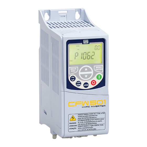
- Page 1 Motors I Automation I Energy I Transmission & Distribution I Coatings Frequency Inverter CFW501 V1.8X Programming Manual...
- Page 3 Programming Manual Series: CFW501 Language: English Document Number: 10002391560 / 01 Software Version: 1.8X Publication Date: 04/2015...
- Page 4 Summary of Reviews The information below describes the reviews made in this manual. Version Review Description V1.5X First edition V1.8X New options of the V/f and VVW Control Type included and modified...
-
Page 5: Table Of Contents
Summary QUICK REFERENCE OF PARAMETERS, ALARMS AND FAULTS ..0-1 1 SAFETY INSTRUCTIONS ..............1-1 1.1 SAFETY WARNINGS IN THIS MANUAL ..................1-1 1.2 SAFETY WARNINGS IN THE PRODUCT ..................1-1 1.3 PRELIMINARY RECOMMENDATIONS ..................1-2 2 GENERAL INFORMATION ..............2-1 2.1 ABOUT THE MANUAL ........................2-1 2.2 TERMINOLOGY AND DEFINITIONS .....................2-1 2.2.1 Terms and Definitions Used ....................2-1 2.2.2 Numerical Representation .................... - Page 6 Summary 9 V/f SCALAR CONTROL ................9-1 9.1 PARAMETERIZATION OF THE V/f SCALAR CONTROL ............. 9-3 9.2 START-UP IN V/f MODE ....................... 9-8 10 V V W VECTOR CONTROL ..............10-1 10.1 VVW VECTOR CONTROL PARAMETERIZATION ..............10-3 10.2 START-UP IN V V W MODE ......................10-8 11 FUNCTIONS COMMON TO ALL THE CONTROL MODES ....
- Page 7 Summary 15 READING PARAMETERS ..............15-1 16 COMMUNICATION ................16-1 16.1 SERIAL RS-485 INTERFACE ......................16-1 16.2 BACNET COMMUNICATION ..................... 16-2 16.3 METASYS N2 COMMUNICATION .................... 16-2 16.4 COMMUNICATION COMMANDS AND STATUS ..............16-2 17 SOFTPLC .................... 17-1 18 HVAC FUNCTIONS ................18-1 18.1 ENERGY SAVING .........................18-1 18.2 PROTECTION AGAINST SHORT CYCLES ................
- Page 8 Summary...
- Page 9 Quick Reference of Parameters, Alarms and Faults QUICK REFERENCE OF PARAMETERS, ALARMS AND FAULTS User Param. Function Adjustable Range Factory Setting Propr. Groups Pag. Setting P0000 Access to Parameters 0 to 9999 P0001 Speed Reference 0 to 65535 rpm READ 15-1 P0002 Motor Speed 0 to 65535 rpm...
-
Page 10: Quick Reference Of Parameters, Alarms And Faults
Quick Reference of Parameters, Alarms and Faults User Param. Function Adjustable Range Factory Setting Propr. Groups Pag. Setting P0029 Power HW Config. 0 = Not Identified READ 1 = 200-240 V / 1.6 A 2 = 200-240 V / 2.6 A 3 = 200-240 V / 4.3 A 4 = 200-240 V / 7.0 A 5 = 200-240 V / 9.6 A... - Page 11 Quick Reference of Parameters, Alarms and Faults User Param. Function Adjustable Range Factory Setting Propr. Groups Pag. Setting P0075 Log. State 3 Fault 0000h to FFFFh READ 14-10 P0080 Last Fault in “Fire Mode” 0 to 999 READ 14-10 P0081 Second Fault in “Fire Mode” 0 to 999 READ 14-10...
- Page 12 Quick Reference of Parameters, Alarms and Faults User Param. Function Adjustable Range Factory Setting Propr. Groups Pag. Setting P0204 Load/Save Parameters 0 to 2 = Not Used 5-11 3 = Reset P0043 4 = Reset P0044 5 = Load 60 Hz 6 = Load 50 Hz 7 = Load User 1 8 = Load User 2...
- Page 13 Quick Reference of Parameters, Alarms and Faults User Param. Function Adjustable Range Factory Setting Propr. Groups Pag. Setting P0210 Main Display Decimal Point 0 = wxyz 1 = wxy.z 2 = wx.yz 3 = w.xyz 4 = According to P0511 5 = According to P0511 6 = Reserved 7 = According to P0511...
- Page 14 Quick Reference of Parameters, Alarms and Faults User Param. Function Adjustable Range Factory Setting Propr. Groups Pag. Setting P0231 AI1 Signal Function 0 = Speed Ref. 12-3 1 = Not Used 2 = Not Used 3 = SoftPLC 4 = PTC 5 = Main PID Feedback 1 6 = Main PID Feedback 2 7 = Not Used...
- Page 15 Quick Reference of Parameters, Alarms and Faults User Param. Function Adjustable Range Factory Setting Propr. Groups Pag. Setting P0253 AO1 Signal Type 0 = 0 to 10 V 12-9 1 = 0 to 20 mA 2 = 4 to 20 mA 3 = 10 V to 0 4 = 20 mA to 0 5 = 20 to 4 mA...
- Page 16 Quick Reference of Parameters, Alarms and Faults User Param. Function Adjustable Range Factory Setting Propr. Groups Pag. Setting P0269 DI7 Function See options in P0263 12-17 P0270 DI8 Function See options in P0263 12-17 P0271 DI1 Function 0 = (DI1..DI8)NPN 12-15 1 = DI1 PNP 2 = (DI1..DI2)PNP...
- Page 17 Quick Reference of Parameters, Alarms and Faults User Param. Function Adjustable Range Factory Setting Propr. Groups Pag. Setting P0289 Ny Speed 0 to 18000 rpm 1800 (1500) rpm 12-24 P0290 Ix Current 0.0 to 200.0 A 1.0xI 12-24 P0291 Zero Speed 0 to 18000 rpm 18 (15) rpm 12-25...
- Page 18 Quick Reference of Parameters, Alarms and Faults User Param. Function Adjustable Range Factory Setting Propr. Groups Pag. Setting P0343 Mask for Faults and Alarms 0000 to FFFFh 0003h 14-4 Bit 0 = F0074 Bit 1 = F0048 Bit 2...3 = Reserved Bit 4 = F0076 Bit 5..15 = Reserved P0349 Ixt Alarm Level...
- Page 19 Quick Reference of Parameters, Alarms and Faults User Param. Function Adjustable Range Factory Setting Propr. Groups Pag. Setting P0510 Ref. Eng. Unit 1 0 = None 1 = V 2 = A 3 = rpm 4 = s 5 = ms 6 = None 7 = m 8 = None...
- Page 20 Quick Reference of Parameters, Alarms and Faults User Param. Function Adjustable Range Factory Setting Propr. Groups Pag. Setting P0513 Indirect Indication Form 2 0 = wxyz 1 = wxy.z 2 = wx.yz 3 = w.xyz P0516 Ref. Eng. Unit 4 See options in P0510 P0517 Indirect Indication Form 4 0 = wxyz...
- Page 21 Quick Reference of Parameters, Alarms and Faults User Param. Function Adjustable Range Factory Setting Propr. Groups Pag. Setting P0690 Logical Status 2 Bit 0..3 = Not Used READ, 7-11 Bit 4 = Force Low Fs Bit 5 = Sleep State Bit 6 = Deceleration Ramp Bit 7 = Acceleration Ramp Bit 8 = Freeze Ramp...
- Page 22 Quick Reference of Parameters, Alarms and Faults User Param. Function Adjustable Range Factory Setting Propr. Groups Pag. Setting P1020 Main PID P. Gain 0.000 to 32.767 1.000 HVAC 17-2 18-12 P1021 Main PID I. Gain 0.000 to 32.767 0.430 HVAC 17-2 18-12 P1022 Main PID D.
- Page 23 Quick Reference of Parameters, Alarms and Faults User Param. Function Adjustable Range Factory Setting Propr. Groups Pag. Setting P1048 Broken Belt Torque 0.0 to 350.0 % 20.0 % HVAC 17-2 18-7 P1049 Broken Belt Time 0.00 to 650.00 s 20.00 s HVAC 17-2 18-7...
- Page 24 Quick Reference of Parameters, Alarms and Faults User Param. Function Adjustable Range Factory Setting Propr. Groups Pag. Setting P1076 External PID Feedback Alarm Low V. -32768 to 32767 HVAC 17-2 18-26 P1077 External PID Feedback Alarm Low T. 0.00 to 650.00 s 5.00 s HVAC 17-2...
- Page 25 Quick Reference of Parameters, Alarms and Faults Fault / Alarm Description Possible Causes A0046 Motor overload alarm. Settings of P0156, P0157, and P0158 are too low for the „ Motor overload used motor. Overload on the motor shaft. „ A0047 Overload alarm on the power pack with Inverter output overcurrent.
- Page 26 Quick Reference of Parameters, Alarms and Faults Fault / Alarm Description Possible Causes A0760 Alarm that indicates the process variable Parameter P1030 is programmed for 1 and the value of the „ Low Level of the Process of the main PID controller has a low process variable of the main PID controller remained below Variable of the Main PID value.
- Page 27 Quick Reference of Parameters, Alarms and Faults Fault / Alarm Description Possible Causes F0031 Main control cannot set a communication Plug-In module is damaged. „ Communication fault with link with the Plug-In module. Plug-In module is not properly connected. „ Plug-In module Problem in the identification of the Plug-In module;...
- Page 28 Quick Reference of Parameters, Alarms and Faults Fault / Alarm Description Possible Causes F0711 The upload or the SoftPLC application Fault in the HVAC plug-in connection. „ The upload of the SoftPLC failed. Fault in the communication between the HVAC plug-in board „...
-
Page 29: Safety Instructions
Safety Instructions 1 SAFETY INSTRUCTIONS This manual contains the information necessary for the correct setting of the frequency inverter CFW501. It was developed to be used by people with proper technical training or qualification to operate this kind of equipment. These people must follow the safety instructions defined by local standards. The noncompliance with the safety instructions may result in death risk and/or equipment damage. -
Page 30: Preliminary Recommendations
If necessary, first touch the grounded metallic frame or use proper grounding strap. Do not execute any applied potential test on the inverter! If necessary, contact WEG. NOTE! Frequency inverters may interfere in other electronic equipments. Observe the recommendations of chapter 3 - Installation and Connection of the user’s manual in order to minimize these effects. -
Page 31: General Information
General Information 2 GENERAL INFORMATION 2.1 ABOUT THE MANUAL This manual presents information necessary for the configuration of all the functions and parameters of the frequency inverter CFW501. This manual must be used together with the user’s manual of the CFW501. The text provides additional information so as to make the use and programming of the CFW501 easier in certain applications. - Page 32 General Information PTC: resistor whose resistance value in ohms increases proportionally to the temperature; it is used as a temperature sensor in motors. NTC: resistor whose resistance value in ohms decreases proportionally to the increase of the temperature; it is used as a temperature sensor in power packs.
-
Page 33: Numerical Representation
General Information Iw: current on phase w (RMS). Ia: output active current (RMS). Hz: hertz. kHz: kilohertz = 1000 hertz. mA: milliampere = 0.001 ampere. min: minute. ms: millisecond = 0.001 seconds. Nm: newton meter; unit of torque. rms: root mean square; effective value. rpm: revolutions per minute;... - Page 34 General Information 2-4 | CFW501...
-
Page 35: About The Cfw501
About the CFW501 3 ABOUT THE CFW501 The frequency inverter CFW501 is a high performance product which enables speed and torque control of three- phase induction motors. This product provides the user with the options of vector (V V W ) or scalar (V/f) control, both programmable according to the application. - Page 36 About the CFW501 = DC link connection = Braking resistor connection Pré- U/T1 R/L1/L carga V/T2 Power S/L2/N Internal Motor supply W/T3 RFI filter T/L3 DC-Inverter Single-phase with IGBT / three-phase transistors rectifier and current feedback Voltage feedback...
- Page 37 About the CFW501 1 – Fixing support (for surface mounting) 2 – Fixing support (for Din-rail mount) 3 – Fan with fixing support 4 – Plug-in module 5 – HMI 6 – Front cover Figure 3.2: Main components of the CFW501 CFW501 | 3-3...
- Page 38 About the CFW501 3-4 | CFW501...
-
Page 39: Hmi And Basic Programming
HMI and Basic Programming 4 HMI AND BASIC PROGRAMMING 4.1 USE OF THE HMI TO OPERATE THE INVERTER Through the HMI, it is possible to view and set all the parameters. The HMI features two operating modes: monitoring and parameterization. The functions of the keys and the active fields on the HMI display vary according to the operating mode. -
Page 40: Indications On The Hmi Display
HMI and Basic Programming 4.2 INDICATIONS ON THE HMI DISPLAY The information shown on the HMI LCD display is divided into five fields: menu, status, secondary display, unit, and main display. Those fields are defined in Figure 4.2: Display areas on page 4-2. -
Page 41: Operating Modes Of The Hmi
HMI and Basic Programming 4.3 OPERATING MODES OF THE HMI The monitoring mode allows the user to view up to two variables of interest, one on the main display, and another on the secondary display. Such fields of the display are defined in Figure 4.2: Display areas on page 4-2. - Page 42 HMI and Basic Programming 4-4 | CFW501...
-
Page 43: Basic Instructions For Programming And Settings
Basic Instructions for Programming and Settings 5 BASIC INSTRUCTIONS FOR PROGRAMMING AND SETTINGS 5.1 PARAMETER STRUCTURE Aiming at simplifying the parameterization process, the CFW501 parameters were classified into ten groups which can be individually selected in the Menu area of the HMI display. When the enter/menu key of the HMI is pressed in the monitoring mode, you enter the setting mode level 1. -
Page 44: Hmi
Basic Instructions for Programming and Settings NOTE! Besides the selected group in the menu field of the HMI, the view of the parameters on the HMI depends on the hardware installed and on the operating mode of the CFW501. Therefore, observe the connected plug-In module, as well as the motor control mode: V V W or V/f. - Page 45 Basic Instructions for Programming and Settings P0200 – Password Adjustable 0 = Inactive Factory 0 = Inactive Range: 1 = Active Setting: 1 to 9999 = New Password Properties: Access groups via HMI: Description: It allows activating the password (by inserting a new value) or disabling it. For further details regarding the use of this parameter, refer to Table 5.2: Required procedure for each kind of action on page 5-3.
- Page 46 Basic Instructions for Programming and Settings P0208 – Main Display Scale Factor P0211 – Secondary Display Scale Factor Adjustable 0.1 to 1000.0 % Factory 100.0 % Range: Setting: Properties: Access groups via HMI: P0210 – Indication Form of the Main Display P0212 –...
- Page 47 Basic Instructions for Programming and Settings P0209 – Main Display Engineering Unit Adjustable 0 = none Factory 1 = V Range: Setting: 2 = A 3 = rpm 4 = s 5 = ms 6 = none 7 = m 8 = none 9 = none 10 = %...
-
Page 48: Indirect Engineering Units
Basic Instructions for Programming and Settings P0216 – HMI Display Light Adjustable 0 = Inactive Factory Range: 1 = Active Setting: Properties: Access groups via HMI: Description: The function of this parameter is to turn on or off the backlight of the HMI display. NOTE! When the remote HMI is connected and activated by P0312, the light of the CFW501 local HMI is cut off and parameter P0216 starts to control the remote HMI. - Page 49 Basic Instructions for Programming and Settings 38 = gal/h 39 = l/s 40 = l/min 41 = l/h 42 = m/s 43 = m/min 44 = m/h 45 = ft/s 46 = ft/min 47 = ft/h 48 = m³/s 49 = m³/min 50 = m³/h 51 = ft³/s 52 = ft³/min...
- Page 50 Basic Instructions for Programming and Settings 5 = ms 6 = none 7 = m 8 = none 9 = none 10 = % 11 = °C 12 = none 13 = Hz 14 = none 15 = h 16 = W 17 = kW 18 = none 19 = none...
- Page 51 Basic Instructions for Programming and Settings P0513 – Indirect Indication Form 2 Adjustable 0 = wxyz Factory Range: 1 = wxy.z Setting: 2 = wx.yz 3 = w.xyz Properties: Access groups via HMI: Description: This parameter selects the decimal point that will be viewed in the user’s parameter of the SoftPLC which is associated to it, that is, any user’s parameter of the SoftPLC that is associated to the indirect indication form 2 will be viewed in this format on the CFW501 HMI.
- Page 52 Basic Instructions for Programming and Settings 34 = m³ 35 = ft³ 36 = gal/s 37 = gal/min (= GPM) 38 = gal/h 39 = l/s 40 = l/min 41 = l/h 42 = m/s 43 = m/min 44 = m/h 45 = ft/s 46 = ft/min 47 = ft/h...
-
Page 53: Backup Parameters
Reset P0044: resets the kWh counter. Load WEG 60 Hz: It loads the default parameters on the inverter with the factory default for 60 Hz. Load WEG 50 Hz: It loads the default parameters on the inverter with the factory default for 50 Hz. -
Page 54: Setting Of Display Indications In The Monitoring Mode
Basic Instructions for Programming and Settings 5.6 SETTING OF DISPLAY INDICATIONS IN THE MONITORING MODE Whenever the inverter is powered up, the HMI display goes to the monitoring mode. In order to simplify the reading of the inverter parameters, the display was designed to indicate two parameters simultaneously, at the user’s discretion. -
Page 55: Identification Of The Inverter Model And Accessories
Identification of the Inverter Model and Accessories 6 IDENTIFICATION OF THE INVERTER MODEL AND ACCESSORIES To verify the inverter model, check the code on the product identification labels: the complete one, on the side of the inverter, or the summarized one, under the HMI. Once the inverter model identification code is checked, it is necessary to interpret it in order to understand its meaning. - Page 56 Identification of the Inverter Model and Accessories P0029 – Power Hardware Configuration Adjustable 0 to 38 Factory Range: Setting: Properties: Access groups READ via HMI: Description: This parameter identifies the inverter model, distinguishing frame, supply voltage and rated current as per Table 6.2: Identification of the CFW501 models for frames A, B, C, D and E on page 6-2.
- Page 57 Identification of the Inverter Model and Accessories P0295 – Inverter Rated Current Adjustable 0.0 to 200.0 A Factory According Range: Setting: to inverter model Properties: Access groups READ via HMI: Description: This parameter presents the inverter rated current as per Table 6.2: Identification of the CFW501 models for frames A, B, C, D and E on page 6-2.
- Page 58 Identification of the Inverter Model and Accessories 6-4 | CFW501...
-
Page 59: Logical Command And Speed Reference
Logical Command and Speed Reference 7 LOGICAL COMMAND AND SPEED REFERENCE The drive of the electric motor connected to the inverter depends on the logical command and on the reference defined by one of the several possible sources, such as: HMI keys, digital inputs (DIx), analog inputs (AIx), serial/ USB interface, SoftPLC, etc. - Page 60 Logical Command and Speed Reference Direction of rotation Run / Stop Control word Control word Direction Control of rotation word Run / Stop All of the inverter command and reference sources (HMI, terminals, networks and SoftPLC) LOC/REM Ramp Speed reference Speed reference Speed reference...
- Page 61 Logical Command and Speed Reference Command selection P0105 and P0223 to P0228 HMI Keys CRS485 P0312 Serial/USB Inverter control word SoftPLC SoftPLC Figure 7.2: Command selection structure CFW501 | 7-3...
- Page 62 Logical Command and Speed Reference Speed reference selection P0221 or P0222 Reference key (P0121) 0 - HMI Keys P0247 8 - FI Frequency 12 - FI > 0 input P0249 P0232 1 - AI1 9 - AI1 > 0 P0234 Inverter speed 4 - AI1 + AI2 >...
- Page 63 Logical Command and Speed Reference P0220 – Local/Remote Selection Adjustable 0 = Always Local Factory Range: 1 = Always Remote Setting: 2 = Local / Remote HMI Key (LOC) 3 = Local / Remote HMI Key (REM) 4 = Digital Input (DIx) 5 = Serial / USB (LOC) 6 = Serial / USB (REM) 7 = SoftPLC...
- Page 64 Logical Command and Speed Reference P0223 – Direction of Rotation Selection – LOCAL Situation P0226 – Direction of Rotation Selection – REMOTE Situation Adjustable 0 = Clockwise Factory P0223 = 2 Range: Setting: 1 = Counterclockwise P0226 = 0 2 = HMI Key (H) 3 = HMI Keys (AH) 4 = DIx 5 = Serial / USB (H)
-
Page 65: Speed Reference
Logical Command and Speed Reference P0225 – JOG Selection – LOCAL Situation P0228 – JOG Selection – REMOTE Situation Adjustable 0 = Inactive Factory P0225 = 1 Range: Setting: 1 = HMI Keys P0228 = 2 2 = DIx 3 = Serial / USB 4 = SoftPLC Properties: Access groups... -
Page 66: Speed Reference Limits
Logical Command and Speed Reference 7.2.1 Speed Reference Limits Although the parameters to adjust the reference have a wide range of values (0 to 18000), the value applied to the ramp is limited by P0133 and P0134. Therefore, the values in module out of this range will have no effect on the reference. -
Page 67: Speed Reference Parameters
Logical Command and Speed Reference 7.2.3 Speed Reference Parameters P0121 – Speed Reference via HMI Adjustable Factory 0 to 18000 rpm 90 rpm Range: Setting: Description: Parameter P0121 stores the speed reference via HMI (P0221 = 0 or P0222 = 0). When the keys " "... -
Page 68: Control Word And Inverter Status
Logical Command and Speed Reference 7.3 CONTROL WORD AND INVERTER STATUS The inverter control word is the grouping of a set of bits to determine the commands received by the inverter from an external source. On the other hand, the status word is another set of bits that define the inverter status. This way, the control and status words establish an interface for the exchanging of information between the inverter and an external module, such as a communication network or a controller. - Page 69 Logical Command and Speed Reference P0690 – Logical Status 2 Adjustable 0000h to FFFFh Factory Range: Setting: Properties: Access groups NET, READ via HMI: Description: Parameter P0690 presents other signaling bits for functions exclusively implemented in the CFW501. The function of each bit of P0690 is described in Table 7.4: Status word (P0680) on page 7-11.
- Page 70 Logical Command and Speed Reference P0682 – Serial / USB Control Adjustable Factory 0000h to FFFFh Range: Setting: Properties: Access groups via HMI: Description: The inverter control word for a certain source is accessible for reading and writing, but read only access is permitted for the other sources.
-
Page 71: Control Via Hmi Inputs
Logical Command and Speed Reference P0229 – Stop Mode Adjustable 0 = Ramp to Stop Factory Range: 1 = Coast to Stop Setting: 2 = Quick Stop Properties: Access groups via HMI: Description: This parameter defines the motor stop mode when the inverter receives the “Stop” command. Table 7.6: Selection of stop mode on page 7-13 describes the options of this parameter. - Page 72 Logical Command and Speed Reference 7-14 | CFW501...
-
Page 73: Available Motor Control Types
Available Motor Control Types 8 AVAILABLE MOTOR CONTROL TYPES The inverter feeds the motor with variable voltage, current and frequency, providing control of the motor speed. The values applied to the motor follow a control strategy, which depends on the selected type of motor control and on the inverter parameter settings. - Page 74 OVERTEMPERATURE PROTECTION (F0051 AND A0050) on page 14-6. ATTENTION! The default setting of P0397 meets most application needs of the inverter. Therefore, avoid modifying its content without knowing the related consequences. If you are not sure, contact WEG Technical Assistance before changing P0397. 8-2 | CFW501...
- Page 75 Available Motor Control Types Table 8.1: Options available to configure the control (P0397) Bit 3 Bit 2 Bit 1 Bit 0 P0397 Reduction of P0297 in Output Current Compensation of Slip Compensation A0050 Stabilization Dead Time During Regeneration 0000h Disabled Disabled Disabled Disabled...
- Page 76 Available Motor Control Types 8-4 | CFW501...
-
Page 77: Scalar Control
V/f Scalar Control 9 V/f SCALAR CONTROL This is the classical control method for three-phase induction motors, based on a curve that relates output frequency and voltage. The inverter works as a variable frequency voltage source, generating a combination of voltage and frequency according to the configured curve. - Page 78 V/f Scalar Control Figure 9.1: Block diagram of V/f scale control 9-2 | CFW501...
-
Page 79: Parameterization Of The V/F Scalar Control
V/f Scalar Control 9.1 PARAMETERIZATION OF THE V/f SCALAR CONTROL The scalar control is the inverter factory default control mode for its popularity and because it meets most applications of the market. However, parameter P0202 allows the selection of other options for the control mode, as per chapter 8 AVAILABLE MOTOR CONTROL TYPES on page 8-1. - Page 80 V/f Scalar Control P0136 – Manual Torque Boost Adjustable 0.0 to 30.0 % Factory According Range: Setting: to inverter model Properties: Access groups BASIC, MOTOR via HMI: Description: This parameter actuates in low speeds, that is, in the range from 0 to P0147, increasing the inverter output voltage to compensate the voltage drop in the motor stator resistance so as to keep the torque constant.
- Page 81 V/f Scalar Control P0142 – Maximum Output Voltage P0143 – Intermediate Output Voltage P0144 – Minimum Output Voltage Adjustable 0.0 to 100.0 % Factory P0142 = 100.0 % Range: Setting: P0143 = 66.7 % P0144 = 33.3 % Properties: cfg, V/f Description: These parameters allow adjusting the inverter V/f curve together with its orderly pairs P0145, P0146 and P0147.
- Page 82 V/f Scalar Control P0137 – Automatic Torque Boost Adjustable 0.0 to 30.0 % Factory 0.0 % Range: Setting: Properties: Access groups MOTOR via HMI: Description: The automatic torque boost compensates the voltage drop in the stator resistance because of active current. Look at Figure 9.1: Block diagram of V/f scale control on page 9-2, where variable m...
- Page 83 V/f Scalar Control P0138 – Slip Compensation Adjustable -10.0 % to 10.0 % Factory 0.0 % Range: Setting: Properties: Access groups MOTOR via HMI: Description: Parameter P0138 is used in the motor slip compensation function, when set for positive values. In this case, it compensates the speed drop due to application of the load on the shaft and, consequently, the slip.
-
Page 84: Start-Up In V/F Mode
V/f Scalar Control 9.2 START-UP IN V/f MODE NOTE! Read chapter 3 - Installation and Connection of the user’s manual before installing, powering up or operating the inverter. Sequence for installation, verification, power up and start-up. 1. Install the inverter: according to chapter 3 - Installation and Connection of the user’s manual, making all the power and control connections. -
Page 85: V W Vector Control
10 V V W VECTOR CONTROL The V V W vector control mode (Voltage Vector WEG) uses a control method with a much higher performance than the V/f control because of the load torque estimation and of the control of the magnetic flux in the air gap, as per scheme of Figure 10.1: VVW control flow on page... - Page 86 V V W Vector Control Figure 10.1: V V W control flow 10-2 | CFW501...
-
Page 87: Vvw Vector Control Parameterization
Below are described the parameters to configure the V V W vector control setting. Those data are easily obtained on the nameplate of WEG motors; however, in old motors or motor of other manufacturers, this information may not be available. In those cases, it is recommended first contact the motor manufacturer, measure or calculate the desired parameter, or, still, make a relationship with Table 10.1: Characteristics of IV pole WEG standard motors... - Page 88 V V W Vector Control Voltage Current Frequency Speed Efficiency Power Stator Power [P0404] Frame [P0400] [P0401] [P0403] [P0402] [P0399] Factor Resistance (CV) (kW) (Hz) (rpm) [P0407] [P0409] (Ω) 0.16 0.12 0.73 1375 57.0 0.72 30.62 0.25 0.18 1.05 1360 58.0 0.74 20.31...
- Page 89 V V W Vector Control Set it according to the value informed on the motor nameplate. It affects the motor overload protection. P0399 – Motor Rated Efficiency Adjustable 50.0 to 99.9 % Factory 75.0 % Range: Setting: Properties: cfg, V V W Access groups MOTOR, STARTUP via HMI:...
- Page 90 V V W Vector Control P0401 – Motor Rated Current Adjustable 0 to 200.0 A Factory 1.0 x I Range: Setting: Properties: Access groups MOTOR, STARTUP via HMI: P0402 – Motor Rated Speed Adjustable 0 to 30000 rpm Factory 1710 rpm Range: Setting: (1425 rpm)
- Page 91 In this case, P0409 will be loaded with the factory default value which is equivalent to WEG IV pole standard motor stator resistance with power matched to the inverter, as per Table 10.1: Characteristics of IV pole WEG standard motors on page...
-
Page 92: Start-Up In V V W Mode
6. Parameterization of the V V W control: browsing the “STARTUP” menu, set parameters P0398, P0399, P0400, P0401, P0402, P0403, P0404 and P0407 according to the data on the motor nameplate. If some of those data are not available, insert the approximate value by calculation or similarity to WEG standard motor – see Table 10.1: Characteristics of IV pole WEG standard motors on page... - Page 93 V V W Vector Control For better visualization of the start-up in the V V W mode, check Figure 10.2: Start-up of the VVW mode on page 10-10, below. Action/Indication on the Display Action/Indication on the Display Monitoring mode. „ Press the ENTER/MENU key to enter the 1 level of the Press the...
- Page 94 V V W Vector Control Action/Indication on the Display Action/Indication on the Display If necessary, modify the content of P0407 – Motor rated „ To exit the STARTUP menu, just press BACK/ESC. „ power factor, or press the key for the next parameter. At this point, the HMI shows the option to do the Self-Tuning.
-
Page 95: Functions Common To All The Control Modes
Functions Common to all the Control Modes 11 FUNCTIONS COMMON TO ALL THE CONTROL MODES This chapter describes the functions common to all the inverter control modes V/f and VVW, but which interferes in the drive performance. 11.1 RAMPS The inverter ramp functions allow the motor to accelerate or decelerate faster or slower. They are adjusted by parameters that define the linear acceleration time between zero and the maximum speed (P0134) and the time for a linear deceleration from the maximum speed to zero. - Page 96 Functions Common to all the Control Modes P0102 – Acceleration Time 2 Ramp Adjustable 0.1 to 999.0 s Factory 10.0 s Range: Setting: Description: Acceleration time from zero to maximum speed (P0134) when the 2 ramp is active. P0103 – Deceleration Time 2 Ramp Adjustable Factory...
-
Page 97: Dc Link Voltage And Output Current Limitation
Functions Common to all the Control Modes P0105 – 1 Ramp Selection Adjustable 0 = 1 Ramp Factory Range: 1 = 2 Ramp Setting: 2 = DIx 3 = Serial/ USB 4 = SoftPLC Properties: Access groups via HMI: Description: It defines the command origin source to activate the 2 Ramp. -
Page 98: Dc Link Voltage Limitation By "Ramp Hold" P0150 = 0 Or 2
Functions Common to all the Control Modes 11.2.1 DC Link Voltage Limitation by “Ramp Hold” P0150 = 0 or 2 It has effect during deceleration only. „ Actuation: when the DC link voltage reaches the level set in P0151, a command is set to the “ramp” block, „... - Page 99 Functions Common to all the Control Modes P0151 – Actuation Level of the DC Link Voltage Regulation Adjustable 339 to 1200 V Factory 400 V Range: Setting: (P0296 = 0) 800 V (P0296 = 1) 1000 V (P0296 = 2) Properties: V/f, V V W Access groups...
- Page 100 Functions Common to all the Control Modes DC link voltage (P0004) F0022- Overvoltage P0151 DC link regulation rated Time Output speed Time Figure 11.3: Example graph of DC link voltage limitation – Ramp Hold (P0152 = 0 or P0152 = 2) Ramp P0100-P0104 Output speed...
-
Page 101: Output Current Limitation By "Ramp Hold" P0150 = 2 Or 3
Functions Common to all the Control Modes DC link voltage (P0004) F0022- Overvoltage P0151 DC link regulation rated Time Output speed Time Figure 11.5: Example graph of the DC ling voltage limitation – Accelerate Ramp (P0152 = 1 or P0152 = 3) Like in the DC link voltage regulation, the output current regulation also has two operating modes: “Ramp Holding”... - Page 102 Functions Common to all the Control Modes P0135 – Maximum Output Current Adjustable Factory 0.0 to 200.0 A 1.5 x I Range: Setting: Properties: V/f, V V W Access groups BASIC, MOTOR via HMI: Description: Current level to activate the current limitation for the ramp hold and decelerate ramp modes, as per Figure 11.6: (a) and (b) Actuation modes of current limitation via P0135 on page 11-8, respectively.
-
Page 103: Flying-Start / Ride-Through
Functions Common to all the Control Modes 11.3 FLYING-START / RIDE-THROUGH The Flying Start function allows driving a motor that is in free spinning, accelerating it from the rotation in which it is. The Ride-Through function allows recovering the inverter, with no locking by undervoltage, when there is an instant drop in the power supply. -
Page 104: Ride-Through Function
Functions Common to all the Control Modes 11.3.2 Ride-Through Function The Ride-Through function will disable the inverter output pulses (IGBT) as soon as the supply voltage reaches a value below the undervoltage value. A fault due to undervoltage (F0021) does not occur and the DC link voltage will slowly drop until the supply voltage returns. - Page 105 Functions Common to all the Control Modes Injection of direct current at starting Output speed Time P0299 P0302 DC Braking Time Stop Figure 11.8: DC braking actuation at start P0300 – DC Braking Time at Stop Adjustable 0.0 to 15.0 s Factory 0.0 s Range:...
- Page 106 Functions Common to all the Control Modes P0301 – Speed to Begin DC Braking at Stop Adjustable 0 to 18000 rpm Factory 30 rpm Range: Setting: Properties: Access groups MOTOR via HMI: Description: This parameter establishes the initial point to apply the DC braking at the stop when the inverter is disabled by ramp, as per Figure 11.9: (a) and (b): Actuation of DC braking at command stop (a) Run/Stop (b) General Enable on page...
-
Page 107: Avoided Speed
Functions Common to all the Control Modes 11.5 AVOIDED SPEED This inverter function prevents the motor from operating permanently at speed values in which, for example, the mechanical system goes into resonance (causing excessive vibration or noises). P0303 – Skip Speed 1 P0304 –... - Page 108 Functions Common to all the Control Modes 11-14 | CFW501...
-
Page 109: Digital And Analog Inputs And Outputs
Digital and Analog Inputs and Outputs 12 DIGITAL AND ANALOG INPUTS AND OUTPUTS This section presents the parameters to configure the CFW501 inputs and outputs. Table 12.1: I/O Configurations of the CFW501 Functions Plug-In Module RS-232 RS-485 10 V 24 V CFW500-CRS485 DI –... - Page 110 Digital and Analog Inputs and Outputs P0230 – Dead Zone of the Analog Inputs Adjustable 0 = Inactive Factory Range: 1 = Active Setting: Properties: Access groups via HMI: Description: This parameter acts just for the analog inputs(AIx) programmed as frequency reference, and defines if the dead zone in those inputs is Active (1) or Inactive (0).
- Page 111 Digital and Analog Inputs and Outputs P0231 – Signal Function AI1 P0236 – Signal Function AI2 P0241 – Signal AI3 Function Adjustable 0 = Speed Reference Factory P0231 = 5 Range: 1 = Not Used Setting: P0236 = 8 2 = Not Used P0241 = 0 3 = SoftPLC 4 = PTC...
- Page 112 Digital and Analog Inputs and Outputs Option 5 (Feedback 1 of Main PID) configures the input to be used as the feedback 1 of the Main PID Controller. The parameter P1026 defines its functionality in the feedback of the Main PID Controller. Option 6 (Feedback 2 of Main PID) configures the input to be used as the feedback 2 of the Main PID Controller.
- Page 113 Digital and Analog Inputs and Outputs P0235 – Input Filter AI1 P0240 – Input Filter AI2 P0245 – Input Filter AI3 Adjustable 0.00 to 16.00 s Factory 0.15 s Range: Setting: Properties: Access groups via HMI: Description: Each analog input of the inverter is defined by the steps of calculation of signal, OFFSET, gain, filter, function and value AIx, as shown in Figure 12.2: Block diagram of the analog inputs –...
- Page 114 Digital and Analog Inputs and Outputs P0243 – Input Signal AI3 Adjustable Factory 0 = 0 to 10 V / 20 mA Range: Setting: 1 = 4 to 20 mA 2 = 10 V / 20 mA to 0 3 = 20 to 4 mA 4 = –10 V to +10 V Properties: Access groups...
-
Page 115: Analog Outputs
Digital and Analog Inputs and Outputs 12.2 ANALOG OUTPUTS The analog outputs (AOx) are configured by means of three types of parameters: function, gain and signal, as per block diagram of Figure 12.3: Block diagram of Analog outputs – AOx on page 12-7. - Page 116 Digital and Analog Inputs and Outputs P0251 – Output Function AO1 P0254 – Output Function AO2 Adjustable 0 = Speed Ref. Factory P0251 = 16 Range: Setting: 1 = Not Used P0254 = 5 2 = Real Speed 3 = Not Used 4 = Not Used 5 = Output Current 6 = Active Current...
- Page 117 Digital and Analog Inputs and Outputs P0252 – Output Gain AO1 P0255 – Output Gain AO2 Adjustable 0.000 to 9.999 Factory 1.000 Range: Setting: Properties: Access groups via HMI: Description: It determines the analog output gain according to the equation of Table 12.3: Full scale of analog outputs on page 12-8.
-
Page 118: Frequency Input
Digital and Analog Inputs and Outputs 12.3 FREQUENCY INPUT A frequency input consists of a fast digital input able to convert the frequency of the pulses in the input into a proportional signal with 10-bit resolution. After the conversion, this signal is used as an analog signal for speed reference, process variable, use of SoftPLC, etc. - Page 119 Digital and Analog Inputs and Outputs P0021 – Value of Frequency Input FI in % Adjustable -100.0 to 100.0 % Factory Range: Setting: Properties: Access groups READ, I/O via HMI: Description: This read-only parameter indicates the value of the frequency input in percentage of full scale. The indicated values are those obtained after the offset action and multiplication by the gain.
- Page 120 Digital and Analog Inputs and Outputs P0247 – Input Gain in Frequency FI Adjustable 0.000 to 9.999 Factory 1.000 Range: Setting: P0248 – Minimum Frequency Input FI Adjustable 10 to 20000 Hz Factory 10 Hz Range: Setting: P0249 – Input Offset in Frequency FI Adjustable -100.0 to 100.0 % Factory...
-
Page 121: Frequency Output
Digital and Analog Inputs and Outputs 12.4 FREQUENCY OUTPUT Like the frequency input is implemented in the digital input DI2, the frequency output is fixed to the transistor digital output DO2. The configuration and resources available in the frequency output are basically the same as those of analog outputs, as shown in Figure 12.5: Block diagram of the output in frequency FO (DO2) on page 12-13. - Page 122 Digital and Analog Inputs and Outputs P0257 – Frequency Output Function FO Adjustable 0 = Speed Reference Factory Range: 1 = Not Used Setting: 2 = Real Speed 3 = Not Used 4 = Not Used 5 = Output Current 6 = Active Current 7 = Output Power 8 = Not Used...
-
Page 123: Digital Inputs
Digital and Analog Inputs and Outputs P0258 – Frequency Output Gain FO Adjustable 0.000 to 9.999 Factory 1.000 Range: Setting: P0259 – Minimum Frequency Output FO Adjustable Factory 10 to 20000 Hz 10 Hz Range: Setting: P0260 – Maximum Frequency Output FO Adjustable Factory 10 to 20000 Hz... - Page 124 Digital and Analog Inputs and Outputs P0012 – Status of Digital Inputs DI8 to DI1 Adjustable Factory Bit 0 = DI1 Range: Setting: Bit 1 = DI2 Bit 2 = DI3 Bit 3 = DI4 Bit 4 = DI5 Bit 5 = DI6 Bit 6 = DI7 Bit 7 = DI8 Properties:...
- Page 125 Digital and Analog Inputs and Outputs P0263 – Function of Digital Input DI1 P0264 – Function of Digital Input DI2 P0265 – Function of Digital Input DI3 P0266 – Function of Digital Input DI4 P0267 – Function of Digital Input DI5 P0268 –...
- Page 126 Digital and Analog Inputs and Outputs a) RUN/STOP It enables or disables the motor rotation through the acceleration and deceleration ramp. Aceleration ramp Deceleration ramp Output speed Time Active Inactive Time Figure 12.6: Example of the Run-Stop function b) GENERAL ENABLE It enables the inverter spin through the acceleration ramp and disables it by cutting off the pulses immediately, the motor stops by inertia.
- Page 127 Digital and Analog Inputs and Outputs d) DIRECTION OF ROTATION If DIx is Inactive, the direction of rotation if clockwise; otherwise, the direction of rotation will be counterclockwise. Clockwise Output speed Time Counterclockwise Active Inactive Time Figure 12.9: Example of the direction of rotation function e) LOCAL / REMOTE If DIx is inactive, the local command is selected;...
- Page 128 Digital and Analog Inputs and Outputs g) 2 RAMP If DIx is inactive, the inverter uses the default ramp by P0100 and P0101; otherwise, it will use the 2 ramp by P0102 and P0103. Active Inactive DIx - Run-Stop Time Active DIx - 2 ramp...
- Page 129 Digital and Analog Inputs and Outputs n) DISABLE FLYING START It allows the DIx, when active, to disable the action of the Flying-Start function preset in parameter P0320 = 1 or 2. When the DIx is inactive, the Flying-Start function operates normally again; Refer to section 11.3 FLYING-START / RIDE-THROUGH on page 11-9.
-
Page 130: Digital Output
Digital and Analog Inputs and Outputs 12.6 DIGITAL OUTPUT The CFW501 can operate up to three digital outputs according to the selected interface plug-in module; refer to Table 12.1: I/O Configurations of the CFW501 on page 12-1. The DO1 digital output is always relay, while DO2 is always transistor; the other outputs can be relay or transistor according to the plug-in module. - Page 131 Digital and Analog Inputs and Outputs Table 12.9: Digital output functions Value Output Function Description Not Used Digital output inactive. N* > Nx Active when the speed reference (P0001) is greater than Nx (P0288). N > Nx Active when the motor speed (P0002) is above Nx (P0288) plus a hysteresis value (P0287) and inactive when the motor speed (P0002) is below Nx (P0288) minus a hysteresis value (P0287).
- Page 132 Digital and Analog Inputs and Outputs P0281 – Fx Frequency Adjustable 0.0 to 500.0 Hz Factory 4.0 Hz Range: Setting: P0282 – Fx Hysteresis Adjustable 0.0 to 15.0 Hz Factory 2.0 Hz Range: Setting: Properties: Access groups via HMI: Description: These parameters set the hysteresis and actuation level on the Fx output frequency signal and on the F* ramp of the relay digital outputs.
- Page 133 Digital and Analog Inputs and Outputs P0291 – Zero Speed Adjustable 0 to 18000 rpm Factory 18 (15 rpm) Range: Setting: Properties: Access groups via HMI: Description: It specifies the value, in rpm, below which the effective speed will be considered zero for the purpose of the Stop Logic function.
- Page 134 Digital and Analog Inputs and Outputs 12-26 | CFW501...
-
Page 135: Rheostatic Braking
Rheostatic Braking 13 RHEOSTATIC BRAKING The braking torque that may be obtained by the application of frequency inverters, without rheostatic braking resistors, varies from 10 % to 35 % of the motor rated torque. In order to obtain higher braking torques, resistors for rheostatic braking are used. In this case, the regenerated energy is dissipated in the resistor mounted outside the inverter. - Page 136 Rheostatic Braking DC link voltage (U ) (P0004) F0022 - Overvoltage P0153 Rheostatic braking actuation rated Time Braking resistor voltage (BR) Time Figure 13.1: Rheostatic braking actuation curve Steps to enable the rheostatic braking: With the inverter powered down, connect the braking resistor (refer to the user’s manual, item 3.2 - Electric „...
-
Page 137: Faults And Alarms
Faults and Alarms 14 FAULTS AND ALARMS The problem detection structure in the inverter is based on the fault and alarm indication. In case of fault, the IGBTs will be locked and the motor will stop by inertia. The alarm works as a warning for the user that critical operating conditions are taking place and that a fault may occur if the situation is not corrected. - Page 138 Faults and Alarms P0156 – Overload Current at Rated Speed P0157 – Overload Current 50 % of Rated Speed P0158 – Overload Current 20 % of Rated Speed Adjustable 0.0 to 200.0 A Factory P0156 = 1.1 x Inom Range: Setting: P0157 = 1.0 x Inom P0158 = 0.8 x Inom...
- Page 139 Faults and Alarms P0349 – Level for Alarm Ixt Adjustable 70 to 100 % Factory 85 % Range: Setting: Properties: Description: This parameter defines the level for alarm actuation of the motor overload protection (A0046 when P0037 > P0349). The parameter is expressed in percentage of the overload integrator limit value, where fault F0072 occurs.
-
Page 140: Igbts Overload Protection (F0048 And A0047)
“Bit” equivalent to “0” disables the respective fault or alarm. Note that the numeric representation of P0343 is hexadecimal. ATTENTION! Disabling the ground fault or overload protections may damage the inverter. Only do that under WEG technical directions. 14-4 | CFW501... -
Page 141: Motor Overtemperature Protection (F0078)
Faults and Alarms 14.3 MOTOR OVERTEMPERATURE PROTECTION (F0078) This function protects the motor against overtemperature through indication of fault F0078. The motor needs a temperature sensor of the triple PTC type. The reading of the sensor can be done in two different ways: through the analog input or through the digital input. -
Page 142: Igbts Overtemperature Protection (F0051 And A0050)
P0397. ATTENTION! An improper change of P0397 may damage the inverter. Only do that under WEG technical directions. 14.5 OVERCURRENT PROTECTION (F0070 AND F0074) The ground fault and output overcurrent protections act very fast by means of the hardware to instantly cut the output PWM pulses when the output current is high. -
Page 143: Link Voltage Supervision (F0021 And F0022)
NOTE! When this fault occurs, contact WEG. 14.12 FAULT IN THE CPU (F0080) The execution of the inverter firmware is monitored at several levels of the firmware internal structure. When some internal fault is detected in the execution, the inverter will indicate F0080. -
Page 144: Incompatible Main Software Version (F0151)
8-1) and the pulse feedback circuit has some defect, fault F0182 will occur. NOTE! When this fault occurs, contact WEG. 14.15 FAULT HISTORY The inverter is able to store a set of data on the last three faults occurred, such as: fault number, current (P0003), DC link voltage CC (P0004), output frequency (P0005), power module temperature (P0030) and logical status (P0680). - Page 145 Faults and Alarms P0051 – Output Current Last Fault P0061 – Output Current Second Fault P0071 – Output Current Third Fault Adjustable Factory 0.0 to 200.0 A Range: Setting: Properties: Access groups READ via HMI: Description: They indicate the output current at the moment of the occurred fault. P0052 –...
- Page 146 Faults and Alarms P0054 – Temperature in the IGBTs Last Fault P0064 – Temperature in the IGBTs Second Fault P0074 – Temperature in the IGBTs Third Fault Adjustable Factory -20 to 150 ºC Range: Setting: Properties: Access groups READ via HMI: Description: These parameters indicate the IGBTs temperature at the moment of the occurred fault.
-
Page 147: Fault Auto-Reset
Faults and Alarms 14.16 FAULT AUTO-RESET This function allows the inverter to execute the automatic reset of a fault by means of the setting of P0340. NOTE! The auto-reset is locked if the same fault occurs three times in a row within 30 seconds after the reset. P0340 –... - Page 148 Faults and Alarms 14-12 | CFW501...
-
Page 149: Reading Parameters
Parâmetros de Leitura 15 READING PARAMETERS In order to simplify the view of the main inverter reading variables, you may directly access the READ – “Reading Parameters” menu of the CFW501 Remote HMI. It is important to point out that all the parameters of this group can only be viewed on the HMI display, and cannot be changed by the user. - Page 150 Parâmetros de Leitura P0005 – Output Frequency (Motor) Adjustable Factory 0.0 to 500.0 Hz Range: Setting: Properties: Access groups READ via HMI: Description: Real frequency instantly applied to the motor in Hertz (Hz). P0006 – Inverter Status Adjustable Factory According to Table 15.1: Inverter status - P0006 on page 15-2 Range: Setting:...
- Page 151 Parâmetros de Leitura P0007 – Output Voltage Adjustable Factory 0 to 2000 V Range: Setting: Properties: Access groups READ via HMI: Description: It indicates the line voltage in inverter output, in Volts (V). P0009 – Motor Torque Adjustable -1000.0 % to 1000.0 % Factory Range: Setting:...
- Page 152 Parâmetros de Leitura P0012 – Digital Input Status Refer to section 12.5 DIGITAL INPUTS on page 12-15. P0013 – Digital Output Status Refer to section 12.6 DIGITAL OUTPUT on page 12-22. P0014 – Analog Output Values AO1 P0015 – Analog Output Values AO2 Refer to section 12.2 ANALOG OUTPUTS on page 12-7.
- Page 153 Parâmetros de Leitura P0030 – Heatsink Temperature Adjustable Factory -20 to 150 ºC Range: Setting: Properties: Access groups READ via HMI: Description: Temperature in ºC measured inside the power module by the internal NTC. P0037 – Motor Overload Ixt Refer to section 14.1 MOTOR OVERLOAD PROTECTION (F0072 AND A0046) on page 14-1.
- Page 154 Parâmetros de Leitura P0044 – kWh Output Energy Adjustable Factory 0 to 65535 kWh Range: Setting: Properties: Access groups READ via HMI: Description: It indicates the energy consumed by the motor. It indicates up to 65535 kWh, and then it gets back to zero. By setting P0204 = 4, the value of the parameter P0044 is reset to zero.
-
Page 155: Communication
Communication 16 COMMUNICATION In order to exchange information via communication network, the CFW501 features several standardized communication protocols, such as Modbus, Bacnet and Metasys N2. For further details referring to the inverter configuration to operate in those protocols, refer to the CFW501 user’s manual for communication with the desired network. -
Page 156: Bacnet Communication
Communication 16.2 BACNET COMMUNICATION P0760 – BACNET Equipment Instance - High Part P0761 – BACNET Equipment Instance - Low Part P0762 – Maximum Master Number P0763 – Maximum MS/TP Frame Number P0764 – I-AM Transmission P0765 – Number of Received Tokens Parameters for configuration and operation of the BACnet communication. -
Page 157: Softplc
SoftPLC 17 SOFTPLC The SoftPLC function allows the inverter to assume PLC (Programmable Logical Controller). For further details regarding the programming of those functions in the CFW501, refer to the CFW501 SoftPLC manual. Below are described the parameters related to the SoftPLC. P1000 –... - Page 158 SoftPLC P1003 – SoftPLC Applicative Selection Adjustable 0 = User Factory 1 = HVAC Range: Setting: Properties: Access groups HVAC via HMI: Description: It allows the user to select the CFW501 built in applications. Table 17.1: Parameter P1003 option description P1003 Description It defines that the application to be executed on the SoftPLC is the one uploaded by the user by means of the...
-
Page 159: Hvac Functions
HVAC Functions 18 HVAC FUNCTIONS The CFW501 frequency inverter is an optimized device for use in heating, ventilation and air conditioning applications, that is, the HVAC market. As a result, some common functionalities/protections for this market sector were added, such as: Automatic energy saving. - Page 160 HVAC Functions P0407 – Motor Rated Power Factor Adjustable 0.50 to 0.99 Factory 0.80 Range: Setting: Properties: cfg, V/f, V V W Access groups MOTOR, STARTUP via HMI: Description: Setting of the motor rated power factor. In order to obtain the proper operation of the energy saving function, the motor power factor must be correctly set, according to the information on the motor nameplate.
-
Page 161: Protection Against Short Cycles
HVAC Functions P0590 – Energy Saving Minimum Speed Adjustable 360 to 18000 rpm Factory 600 (525) rpm Range: Setting: Properties: cfg, V/f Access groups HVAC via HMI: Description: This parameter defines the minimum speed value at which the energy saving function will remain active. The hysteresis for the minimum speed level is of 2 Hz. -
Page 162: Dry Pump
HVAC Functions P0586 – Minimum Run Time Adjustable 0 to 650.00 s Factory 5.00 s Range: Setting: Properties: Access groups HVAC via HMI: Description: It defines a minimum length of time the compressor will be kept running, not accepting a “Stop” command. P0587 –... - Page 163 HVAC Functions P1043 – Dry Pump Detection Speed Adjustable 0 to 18000 Factory Range: Setting: Properties: Access groups HVAC via HMI: Description: This parameter defines the speed above which will be enabling to compare the actual motor torque with the motor torque for dry pump detection set in P1044.
-
Page 164: Broken Belt
HVAC Functions 18.4 BROKEN BELT This parameter group allows the user to configure the broken belt operation detection. The broken belt detection is intended to avoid the motor driven by frequency inverter to operate empty, i.e., to a mechanical problem between the motor and load, it continues to operate. This is done by detecting the operation speed in conjunction with the motor torque. -
Page 165: Filter Maintenance Alarm
HVAC Functions P1048 – Broken Belt Detection Motor Torque Adjustable 0.0 to 350.0 % Factory 20.0 % Range: Setting: Properties: Access groups HVAC via HMI: Description: This parameter defines the motor torque value below which will be detected the broken belt condition P1049 –... -
Page 166: Main Pid Controller
HVAC Functions P1051 – Filter Maintenance Alarm Time Adjustable Factory 0 to 32000 h 5000 h Range: Setting: Properties: Access groups HVAC via HMI: Description: This parameter defines the operation time of motor driven by CFW501 frequency inverter needed to be done changing the filter system. - Page 167 HVAC Functions P1011 – Main PID Controller Automatic Setpoint Adjustable -32768 to 32767 Factory Range: Setting: Properties: Access groups HVAC via HMI: Description: This parameter defines the value of Main PID controller setpoint in engineering unit when it is in automatic mode. NOTE! This parameter is displayed as the selection in the indirect engineering unit 1 parameters (P0510 and P0511).
- Page 168 HVAC Functions P1017 – Main PID Controller Action Control Adjustable 0 = Disable PID Factory Range: 1 = Direct Mode Setting: 2 = Reverse Mode Properties: Access groups HVAC via HMI: Description: This parameter defines how the action control or regulation of Main PID controller. Table 18.4: Description of Main PID controller action control P1017 Description...
- Page 169 HVAC Functions P1018 – Main PID Controller Operation Mode Adjustable 0 = Always Automatic Factory Range: 1 = Always Manual Setting: 2 = Automatic or Manual selection via DIx and transition without bumpless 3 = Automatic or Manual selection via Network and transition without bumpless 4 = Automatic or Manual selection via DIx and transition with bumpless...
- Page 170 HVAC Functions P1019 – Main PID Controller Sampling Time Adjustable 0.10 to 60.00 s Factory 0.10 s Range: Setting: Properties: Access groups HVAC via HMI: Description: This parameter defines the sampling time of the Main PID controller. P1020 – Main PID Controller Proportional Gain Adjustable 0.000 to 32.767 Factory...
- Page 171 HVAC Functions P1023 – Main PID Controller Output Minimum Value Adjustable 0.0 to 100.0 % Factory 0.0 % Range: Setting: Properties: Access groups HVAC via HMI: Description: This parameter defines the minimum output value of the Main PID controller. P1024 – Main PID Controller Output Maximum Value Adjustable 0.0 to 100.0 % Factory...
- Page 172 HVAC Functions P1027 – Minimum Level for Process Variable of the Main PID Controller Adjustable -32768 to 32767 Factory Range: Setting: Properties: Access groups HVAC via HMI: Description: This parameter defines the minimum value of the analog input sensor configured for process variable of the main PID controller according to its engineering unit.
- Page 173 HVAC Functions P1030 – Main PID Feedback Alarm Conf. Adjustable 0 = Disable Factory Range: 1 = Enable Alarm Setting: 2 = Enable Fault Properties: Access groups HVAC via HMI: Description: This parameter defines how the low level and high level alarm conditions will be handled for the process variable of the main PID controller.
- Page 174 HVAC Functions P1032 – Time for Low Level Alarm of the Process Variable of the Main PID Controller Adjustable 0.00 to 650.00 s Factory 5.00 s Range: Setting: Properties: Access groups HVAC via HMI: Description: This parameter defines the time with the low level condition of the process variable of the main PID controller, so that the alarm message “A0760: Low level alarm of the process variable of the main PID controller“...
- Page 175 HVAC Functions P1034 – Time for High Level Alarm of the Process Variable of the Main PID Controller Adjustable Factory 0.00 to 650.00 s 5.00 s Range: Setting: Properties: Access groups HVAC via HMI: Description: This parameter defines the time with the high level condition of the process variable of the main PID controller, so that the alarm message “A0762: High level alarm of the process variable of the main PID controller“...
- Page 176 HVAC Functions P1037 – Main PID Controller Sleep Mode Time Adjustable 0.00 to 650.00 s Factory 5.00 s Range: Setting: Properties: Access groups HVAC via HMI: Description: This parameter defines a time with the motor speed in low conditions for the controlled system is in sleep mode, will be generated the alarm message “A0764: Sleep Mode Active”.
- Page 177 HVAC Functions Process Variable P1011 - Main PID Controller Automatic Setpoint P1038 - Main PID controller wake up percentage deviation P1039 - Time to activate the wake up mode MOTOR SPEED P0134 - Maximum Speed (rpm) P1037 - Time to activate the sleep mode P1036 - Speed to Activate the Sleep Mode...
-
Page 178: External Pid Controller
HVAC Functions 18.7 EXTERNAL PID CONTROLLER This parameter group allows the user to configure the External PID controller operation. The External PID controller allows controlling an external actuator to the CFW501 frequency inverter via analog output by comparing the process variable control (feedback) with the required setpoint. The process variable is the one the PID controller uses as feedback of its control actions being compared to the required control setpoint, thus generating the error for the control. - Page 179 HVAC Functions P1062 – Process Variable of the External PID Controller Adjustable -32768 to 32767 Factory Range: Setting: Properties: Access groups HVAC via HMI: Description: This parameter shows the actual value of the process variable of the main PID controller in engineering unit. NOTE! This parameter is displayed as the selection in the indirect engineering unit 2 parameters (P0512 and P0513).
- Page 180 HVAC Functions P1065 – External PID Controller Operation Mode Adjustable 0 = Always Automatic Factory Range: 1 = Always Manual Setting: 2 = Automatic or Manual selection via DIx and transition without bumpless 3 = Automatic or Manual selection via Network and transition without bumpless 4 = Automatic or Manual selection via DIx and transition with bumpless...
- Page 181 HVAC Functions P1066 – External PID Controller Sampling Time Adjustable 0.10 to 60.00 s Factory 0.10 s Range: Setting: Properties: Access groups HVAC via HMI: Description: This parameter defines the sampling time of the External PID controller. P1067 – External PID Controller Proportional Gain Adjustable Factory 0.000 to 32.767...
- Page 182 HVAC Functions P1070 – External PID Controller Output Minimum Value Adjustable 0.0 to 100.0 % Factory 0.0 % Range: Setting: Properties: Access groups HVAC via HMI: Description: This parameter defines the minimum output value of the External PID controller. P1071 – External PID Controller Output Maximum Value Adjustable 0.0 to 100.0 % Factory...
- Page 183 HVAC Functions P1074 – Maximum Level for Process Variable of the External PID Controller Adjustable -32768 to 32767 Factory 1000 Range: Setting: Properties: Access groups HVAC via HMI: Description: This parameter defines the maximum value of the analog input sensor configured for feedback of the external PID controller according to its engineering unit.
- Page 184 HVAC Functions P1076 – Value for Low Level Alarm of the Process Variable of the External PID Controller Adjustable -32768 to 32767 Factory Range: Setting: Properties: Access groups HVAC via HMI: Description: This parameter defines the value below which it will be considered low level for the process variable of the external PID controller according to its engineering unit.
- Page 185 HVAC Functions P1078 – Value for High Level Alarm of the Process Variable of the External PID Controller Adjustable -32768 to 32767 Factory Range: Setting: Properties: Access groups HVAC via HMI: Description: This parameter defines the value above which the process variable of the external PID controller will be considered high level according to its engineering unit.
-
Page 186: Hvac Functions Logical Status
HVAC Functions 18.8 HVAC FUNCTIONS LOGICAL STATUS This parameter group allows the user to monitoring the status of HVAC functions. P1040 – HVAC Functions Logical Status Adjustable 0000h to FFFFh Factory Range: Setting: Properties: Access groups HVAC via HMI: Description: This parameter allows the user to monitoring the logical status of HVAC functions. -
Page 187: Fire Mode
„ the “Fire Mode” function. WEG strongly recommends to follow the cares and procedures above before using the CFW501 „ in the “Fire Mode” function, and it will not be liable to the final user or third parties for any losses or damages direct or indirectly incurred due to the programming and operation of the CFW501 in “Fire Mode”... - Page 188 HVAC Functions P0580 – Configuration “Fire Mode” Adjustable 0 = Disabled (“Fire Mode” inactive) Factory Range: 1 = Enabled (keeps speed reference/PID setpoint) Setting: 2 = Enabled (set speed reference to maximum [P0134]) 3 = Enabled (set PID setpoint to the value programmed in P0581) 4 = Enabled (general disable, motor will coast to stop) Properties: Access groups...
-
Page 189: Bypass Mode
HVAC Functions P0582 – Fire Mode Auto-reset Adjustable 0 = Limited Factory Range: 1 = Unlimited Setting: Properties: Access groups HVAC via HMI: Description: This parameter defines how the auto-reset functionality will work in Fire Mode when a critical fault occur (DC Bus Overvoltage (F0022) and Overcurrent/Short-circuit (F0070)). - Page 190 HVAC Functions DIx/Fault CFW501 Bypass drive P0584 desm desm Line P0584 P0006 P0680 Figure 18.2: Bypass mode activation logic An example of connecting the bypass can be seen in Figure 18.3: Bypass mode example on page 18-33. Setting used in this example: P0268 = 23 (DI6 = Bypass Mode) P0275 = 39 (RL1 = Drive Bypass Contactor) P0276 = 40 (RL2 = Mains Bypass Contactor)
- Page 191 HVAC Functions 220 V MDW16 MDW40 Bypass Circuit Circuit command breaker breaker 11 15 18 35 36 31 32 33 CFW501 220 V - 64 / 5 A R S T U V W 1 3 5 1 3 5 CWC07 - 10E CWC07 - 10E Mains contactor...
- Page 192 HVAC Functions P0583 – Mode Configuration “Bypass” Adjustable 0 = Inactive Factory Range: 1 = Active/DIx Setting: 2 = Active/DIx+Failure Properties: Access groups HVAC via HMI: Description: This parameter configured the triggering event for the CFW501 entering the Bypass Mode. Table 18.14: Options for the parameter P0583 P0583 Description...
Need help?
Do you have a question about the CFW501 V1.8X and is the answer not in the manual?
Questions and answers