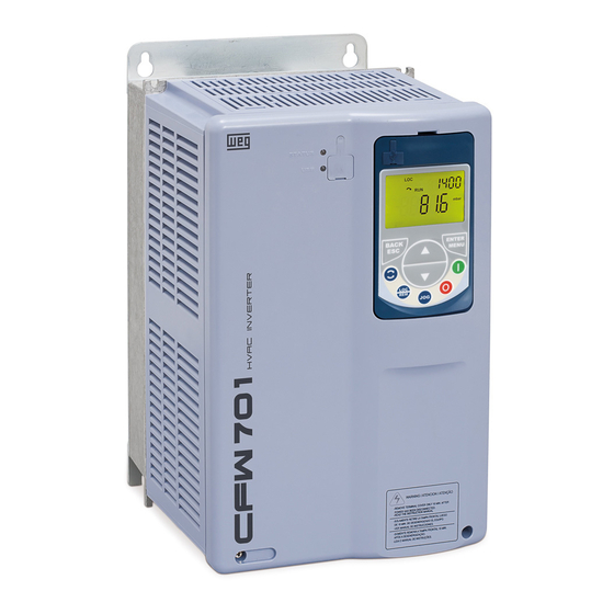
WEG CFW701 Quick Setup Manual
Hvac-r drives
Hide thumbs
Also See for CFW701:
- Addendum to the programming and troubleshooting manual (7 pages) ,
- User manual (31 pages) ,
- User manual (191 pages)

Related Manuals for WEG CFW701


Summary of Contents for WEG CFW701
- Page 1 Motors | Automation | Energy | Transmission & Distribution | Coatings CFW701 HVAC-R Drives Quick Setup Guide...
- Page 2 CFW701 HVAC-R Drives 1 - Installation and Power Connections Refer to CFW701 user guide chapter 3. 1.1 - Control Connections 4-20 mA Sensor AI1+ Analog input 1 (4-20 mA): Control Process Variable AI1- Common point of the digital inputs...
-
Page 3: Control Configuration
1.2 - Control Configuration PROG User Description 2 - Wire start/stop P0000 Access to parameters LOC/REM selection = LR key P0220 (REM when turn on CFW701) Press to select remote mode P0227 Remote run/stop = DIx P0263 DI1 = start/stop BACnet communication P0308 Δ... - Page 4 2 - Programming 2.1 - CFW701 Keypad Back/ESC Enter/Menu Return to Enter programming monitoring mode mode Return to previous Use to select/save programming level Up/Down Adjust speed Run in local mode in local mode Navigate through parameters Stop Stop in local mode Reset 2.2 - Motor and Keypad Settings...
- Page 5 PROG User Description Basic application - BASIC group P0100 Δ Acceleration time (s) P0101 Δ Deceleration time (s) P0133 90 rpm Δ Minimum speed (Hz) P0134 1,800 rpm Δ Maximum speed (Hz) Note: Δ Setting depends on application. PROG...
-
Page 6: Fire Mode
Fire Mode This function makes the drive to inhibit its internal faults making the motor run at adverse conditions without stopping the process. Alarm A211 will be generated on keypad when Fire Mode is enable. PROG User Description P0269 - DI7 function... - Page 7 1 = enabled by a digital input 2 = enabled by a digital input or when a fault happens Deine the triggering event for the CFW701 entering the Bypass Mode P0584 - Bypass contactor time Delay between the opening of one contactor P0584 0.30s...
- Page 8 Dry Pump Prevents the pump from running with no load. Pump protection PROG User Description Dry pump P0516 3 = rpm P0517 Decimal point of engineering unit = xywz 0 = disable P1042 Δ 1 = enable and generates only alarm (A0766)
-
Page 9: Broken Belt
Broken Belt Monitors motor torque and prevents VFD from running with no load in case of a broken belt. PROG User Description Broken belt P0516 3 = rpm P0517 Decimal point of engineering unit = xywz 0 = disable P1046 Δ... -
Page 10: Filter Maintenance Alarm
Filter Maintenance Alarm Warns about the need to replace the filter. PROG User Description Filter maintenance 0 = disable P1050 1 = enable and generates only alarm (A0770) Δ 2 = enable and generates fault (F0771) P1051 5,000h Filter maintenance time (0 to 32,000h) - Page 11 Short Cycle Protection Prevents compressor/motor from being switched on and off in short period of times. Run/stop commands are ignored, with the exception of “general disable” and faults. Compressor function protection PROG User Description Short cycle protection 0 = disable...
-
Page 12: Energy Saving
flux is reduced decreasing losses and therefore efficiency is improved. Fans and pumps applications Energy (%) Flow (%) Valve CFW701 with energy saving enable PROG User Description Energy saving (V/F operation mode) ■ P0407 0.68 Motor rated power factor... -
Page 13: System Configuration
Enable P0009 Actual Motor Torque (%) P0591 Torque Histeresis P0588 Maximum Torque (%) ENERGY SAVING Algorithm P0002 Running Actual Motor Speed (rpm) Save energy, Save money, GO GREEN. P0590 Minimum Speed (rpm) Input Data P0589 Minimum Voltage Level (%) - Page 14 2) Only change these parameters if it is necessary to improve the system response. Important: CFW701 offers two (AI2 and AI3) external PID Controllers for use to control independent process variables (it might be for the control of external process not related to what the main PID loop is handling).
-
Page 15: System Protection
System Protection PROG User Description Alarm or fault configuration 0 = disable P1030 Δ 1 = enable and generates only alarm (A0760 and A0762) 2 = enable and generates fault (F0761 and F0763) Low level protection (example broken pipe for pumps) -
Page 16: Sleep / Wake-Up Mode
3 = (rpm) P0517 Decimal point of engineering unit = wyw.z Sleep Mode P1036 Motor speed below which CFW701 goes to Sleep Mode (rpm) P1037 Δ Time delay for CFW701 goes to Sleep Mode (s) TIMER ON Motor Speed (rpm)
Need help?
Do you have a question about the CFW701 and is the answer not in the manual?
Questions and answers