
Related Manuals for WEG CFW11W G2 Series


Summary of Contents for WEG CFW11W G2 Series
- Page 1 Motors I Automation I Energy I Transmission & Distribution I Coatings Frequency Inverter CFW11W G2 User's Manual...
- Page 2 User's Manual Series: CFW11W G2 Language: English Document: 10006249713 / 01 Models: 780...3705 A/500...690 V Publication Date: 05/2020...
- Page 3 Summary of Reviews The table below describes all revisions made to this manual. Revision Description Chapter First edition Coolant's inhibitor concentration change, preventive maintenance review and general corrections...
-
Page 4: Table Of Contents
Contents 1 SAFETY INSTRUCTIONS ............... 1-1 1.1 SAFETY NOTICES IN THE MANUAL ....................1-1 1.2 SAFETY WARNINGS ON THE PRODUCT ..................1-1 1.3 PRELIMINARY RECOMMENDATIONS ..................1-2 2 GENERAL INFORMATION ..............2-1 2.1 ABOUT THE MANUAL ........................2-1 2.2 TERMS AND DEFINITIONS USED IN THE MANUAL ..............2-1 2.3 ABOUT THE CFW11W G2 ....................... - Page 5 Contents 3.4 INSTALLATIONS ACCORDING TO THE EUROPEAN ELECTROMAGNETIC COMPATIBILITY DIRECTIVE ......................3-47 3.4.1 Conformal Installation ......................3-47 3.4.2 Definition of the Standards ....................3-47 3.4.3 Emission and Immunity Levels Met .................. 3-48 4 HMI......................4-1 4.1 HMI-CFW11W G2 HUMAN MACHINE INTERFACE ..............4-1 4.2 PARAMETER STRUCTURE ......................
-
Page 6: Safety Instructions
Safety Instructions 1 SAFETY INSTRUCTIONS This manual contains the information necessary for the correct use of the CFW11W G2 frequency inverter. It was developed to be used by people with proper technical qualification or training to operate this kind of equipment. -
Page 7: Preliminary Recommendations
Only the user’s manual is supplied in print. The other manuals can be obtained on WEG website - www.weg.net. A printed copy of this information may be requested through your local WEG representative. -
Page 8: General Information
„ Anybus-CC communication manual. „ Those manuals are available on WEG website - www.weg.net. 2.2 TERMS AND DEFINITIONS USED IN THE MANUAL Normal Duty (ND): operating duty of the inverter that defines the maximum current values for continuous operation and overload of 110 % for one minute. It is selected by programming P0298 (Application) = 0 (Normal Duty nom-ND (ND)). - Page 9 General Information Pre-Charge Circuit: it loads the capacitors of the DC link with limited current, avoiding high current peaks at the inverter energization. DC Link: intermediate circuit of the inverters; voltage in direct current obtained by rectifying the alternate supply voltage or through an external power supply;...
- Page 10 General Information °C: degrees Celsius. AC: alternating current. DC: direct current. CFM: cubic feet per minute; a flow measurement unit. cm: centimeter. CV: Brazilian unit of power = 736 Watts; usually used to indicate mechanical power of electric motors. ft: foot. hp: Horse power = 746 Watts;...
-
Page 11: About The Cfw11W G2
General Information 2.3 ABOUT THE CFW11W G2 CFW11W G2 inverters are the second generation of CFW11W inverters. The main differences in relation to the previous generation are the following: Smaller. CFW-11M G2 is shorter, slimmer and less deep than the CFW11W, allowing the installation of 3 UP11W „... - Page 12 General Information Cooling system UP11W electronics 24 Vdc external UP11W 3 power suppl UP11W 2 UP11W 1 Motor DC Power Supply Capacitor Inverter Bank with IGBT transistors RFI Filter Feedbacks: - voltage - current ICUP Control Power supply of electronics and interfaces between power and control Power UC11 Electronics 24 Vdc External...
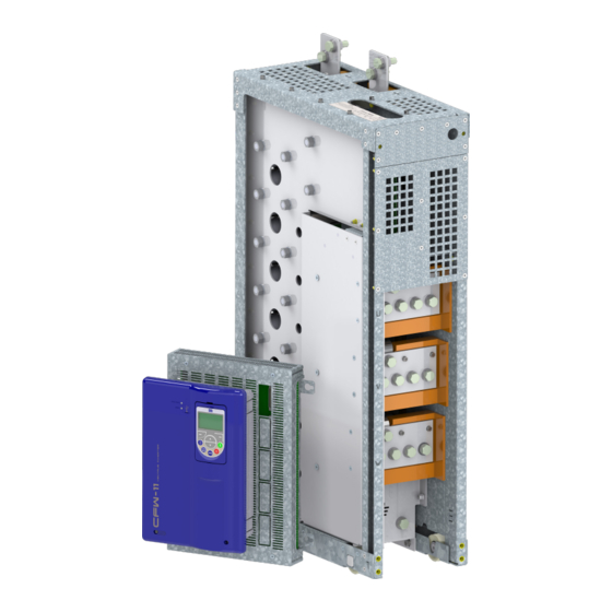
- Page 13 General Information Figure 2.2: Power unit (UP11W G2) Figure 2.3: Control unit (UC11 G2) 2-6 | CFW-11W G2...
-
Page 14: Uc11 G2 Nameplate
It is not necessary to include a current transformer (CT) in the drive for protection against short circuit to the ground in the output, since each UP11W G2 has its own internal protection. 2.4 UC11 G2 NAMEPLATE The UC11 G2 nameplate is located on the control rack. WEG Material UC11 model Serial Manufacturing date (30... -
Page 15: Up11W G2 Nameplate
The nameplate is located on the front of the UP11W G2. Manufacturing date (48 corresponds to the week and H to the year) Model of the UP11W MOD.: UP11W-01 G2 48 H WEG part number Serial number MAT.: 14133179 SERIAL#: 1234567890 Maximum ambient temperature OP.: 12345678 MAX. -
Page 16: How To Specify The Model Of The Cfw11W G2 (Smart Code)
General Information 2.6 HOW TO SPECIFY THE MODEL OF THE CFW11W G2 (SMART CODE) In order to specify the model of the CFW11W G2, it is necessary to replace the smart code values with the desired rated supply voltage and rated output current in the respective fields for operation under normal duty (ND), as shown in the example of Table 2.1 on page 2-9. -
Page 17: Receipt And Storage
General Information E.g.: CFW11WG21482T6OYZ corresponds to a CFW11W G2 three-phase inverter of 1482 A, with input supply voltage from 500 V to 690 V, with optional safety stop. The options for the inverter rated current under normal duty (ND) are in Table 2.2 on page 2-10, according to the inverter rated output voltage. -
Page 18: Installation And Connection
Installation and Connection 3 INSTALLATION AND CONNECTION This chapter describes the electrical and mechanical installation procedures for the CFW11W G2. The directions and suggestions must be observed so as to ensure the safety of people and equipment, and the proper operation of the inverter. -
Page 19: Lifting
Installation and Connection Table 3.2: Cable set items WEG Item Cable Set 13555095 2.5 m Cables 13555150 3.0 m Cables 13555151 3.6 m Cables The panel builder must provide the other parts of the drive. Among those parts are the rectifier, power busbar, pre-charge circuit, panel fans, protection fuses and input reactance. - Page 20 Installation and Connection [14.161] 359.7 [1.185] [4.909] 30.1 359.7 [0.362] ∅ 9.2 [0.362] ∅ 9.2 [19.047] [21.803] 483.8 553.8 SECTION H-H [0.362] ∅ 9.2 [19.083] 484.7 Figure 3.2: Dimensions of Rack 2 G2 in (mm) [in] CFW-11W G2 | 3-3...
- Page 21 Installation and Connection [18.1] [1.2] 459.7 [8.8] 30.1 224.7 [0.4] ∅ 9.2 [0.4] ∅ 9.2 [21.8] [19] 553.8 483.8 SECTION A-A [0.4] ∅ 9.2 [27] 684.7 Figure 3.3: Dimensions of Rack 3 G2 in mm [in] 3-4 | CFW-11W G2...
-
Page 22: Panel
Installation and Connection Figure 3.4: Insertion of the power modules into Rack 3 G2 3.1.5 Panel The minimum panel dimensions are subject to the quantity of UP11Ws G2 of the drive. Figure 3.5 on page 3-5, Figure 3.6 on page 3-6, Figure 3.7 on page 3-6,... - Page 23 Installation and Connection Panel Width At least 600 mm Panel Height At least 2000 mm Panel Depth At least 600 mm Weight Capacity 156 kg Figure 3.6: Panel data for a drive with 2 UP11W G2 Panel Width At least 800 mm Panel Height At least 2000 mm Panel Depth...
- Page 24 Installation and Connection Figure 3.10: Column with 3 UP11W G2 installed Mounting of the UC11 G2 on the panel door: control rack with flange mount and ICUP board shield mounted inside the door. The control rack is mounted with four screws M3 (recommended torque: 0.5 N.m). ICUP Figure 3.11: Example of mounting of the control rack in the panel CFW-11W G2 | 3-7...
- Page 25 Installation and Connection ø 5.2 (4X) (7.48) (0.20) R8 (4x) (0.32) 186.5 (7.34) 93.3 (3.67) 7 (0.27) 7 (0.27) (0.43) Figure 3.12: Mounting of the control rack and necessary slots in mm (in) [11.2] 283.6 [0.2] R4 (4x) Figure 3.13: Mounting of the base of the ICUP1 module in mm (in) The shield of the ICUP board is mounted with four screws M6 (recommended torque: 8.5 N.m).
-
Page 26: Cooling System
Installation and Connection 3.1.6 Cooling System Figure 3.14 on page 3-9 shows the details of the coolant inlet and outlet. Coolant inlet Coolant outlet Figure 3.14: Detail of the coolant inlet and outlet Table 3.3 on page 3-9 contains detailed specifications of the UP11W G2 cooling system. Table 3.3: Cooling system specifications From 0 ºC to 45 ºC (32 °F to 113 °F) according to the coolant;... - Page 27 Installation and Connection ATTENTION! It is recommended the use of stainless steel hydraulic connections in the application cooling system. Figure 3.16 on page 3-10 shows a simplified diagram of a closed cooling system for the UP11W G2. Degassing valve Over pressure valve Temperature transmitter Diaphragm Pressure transmitter...
- Page 28 Installation and Connection NOTA! WEG RSW cooling system can be used for cooling the CFW11W G2. For further information, refer to the RSW user's manual. The water used in the coolant must meet the specifications of Table 3.4 on page 3-11.
-
Page 29: Electrical Installation
Installation and Connection Condensation may occur when the incoming water temperature is too lower than the ambient temperature. The water temperature to avoid condensation varies according to the air relative humidity and ambient temperature. The temperature at which the water vapor contained in the air turns into liquid as small water drops is known as "dew point". -
Page 30: Input Rectifier
Active Front End (AFE), diode rectifier of 6, 12, 18 pulses or more. The following items contain general directions on the sizing of a 6-pulse rectifier. For further information on multipulse rectifiers or AFE, contact WEG. 3.2.1.1 Sizing The main rectifier bridge is sized according to the drive rated power. -
Page 31: Pre-Charge
Installation and Connection 3.2.1.3 Pre-Charge The resistors of the pre-charge circuit must be sized according to the following criteria: Maximum voltage. „ Maximum energy. „ Power overload capacity of the resistors during the pre-charge period (energy dissipation capacity). „ Table 3.8: Sizing of the pre-charge Peak Current During the Pre-charge (A) 0.82 x (V line... - Page 32 Installation and Connection Rectifier UP11 G2 line Motor Line KPCR Stop XC1:22 220 Vac CC11 (DO1) external XC1:23 XC1:22 KPCR KPCR Figure 3.17: Example of a pre-charge activation circuit The Input Rectifier of the CFW-11W G2 can be supplied via contactor or motorized circuit breaker (represented by K1), and its command must be interlocked with the command of the KPCR pre-charge contactor.
-
Page 33: Harmonics Of The 6-Pulse Rectifier
Installation and Connection 3.2.1.4 Harmonics of the 6-Pulse Rectifier Table 3.4 on page 3-11, Figure 3.18 on page 3-16 Figure 3.19 on page 3-16 show typical harmonic content values of the currents, Power Factor and THD(I) on the power line, considering the 6-pulse rectifier. Table 3.9: Typical individual harmonics, Power Factor and THD (I) for rated load in the output. -
Page 34: Harmonics Of The 12-Pulse Rectifier
Installation and Connection 3.2.1.5 Harmonics of the 12-Pulse Rectifier Table 3.11 on page 3-18, Figure 3.20 on page 3-17 Figure 3.21 on page 3-17 show the typical harmonic content values of the currents, Power Factor and THD(I) on the power line, considering the 12-pulse rectifier. Table 3.10: Typical individual harmonics, Power Factor and THD (I) for rated load in the output. -
Page 35: Harmonics Of The 18-Pulse Rectifier
Installation and Connection 3.2.1.6 Harmonics of the 18-Pulse Rectifier Table 3.7 on page 3-12, Figure 3.22 on page 3-18 Figure 3.23 on page 3-18 show the typical harmonic content values of the currents, Power Factor and THD(I) on the power line, considering the 18-pulse rectifier. Table 3.11: Typical individual harmonics, Power Factor and THD(I) for rated load in the output. -
Page 36: Busbars
Installation and Connection NOTE! The harmonics shown in Item 3.2.1.4 Harmonics of the 6-Pulse Rectifier on page 3-16, Item 3.2.1.5 Harmonics of the 12-Pulse Rectifier on page 3-17 Item 3.2.1.6 Harmonics of the 18-Pulse Rectifier on page 3-18 are typical values and may vary according to the application. The data shown are valid for the following condition: Short circuit current of the transformer: 100000 symmetric Arms „... - Page 37 Installation and Connection UC11 ICUP UP11W XC33 24 Vdc CC11 UP11W XC33 24 Vdc UP11W MOTOR XC33 24 Vdc Error_BR UP11W XC33 24 Vdc UP11W 24 Vdc Figure 3.24: General wiring diagram 3-20 | CFW-11W G2...
-
Page 38: Power Connections
Installation and Connection 3.2.5 Power Connections DC Power Supply Figure 3.25: Power and grounding connections ATTENTION! The protective earth of the motor must be connected to the panel ground. The fastening of the DC+ and DC- connections of the UP11W G2 is done with 4 screws M12X35 (recommended torque: 60 N.m);... - Page 39 Installation and Connection Figure 3.26: DC power supply terminals DC+: Positive pole of the DC power supply. DC-: Negative pole of the DC power supply. The U, V and W connections are made through 12 screws M12X25 (recommended torque: 60 N.m; see Figure 3.27 on page 3-23).
- Page 40 Installation and Connection Figure 3.27: U, V, W and grounding terminals U, V and W: connections to the motor. : Grounding cable connection. For a better current distribution between the UP11W G2, it is recommended that their output connections be interconnected through a single paralleling busbar.
-
Page 41: Input Connections
3-25, sized to withstand the DC link current, according to Table 8.1 on page 8-2. Figure 3.30 on page 3-25 shows an example of flexible braid used by WEG, using a fuse on DC+ and another on DC-. 3-24 | CFW-11W G2... -
Page 42: Output Connections
Installation and Connection Figure 3.29: Side view of the connections of the flexible braids and fuses ø 14 (3x) (0.55) (0.67) (1.02) (0.98) 8±1 (2.36) (1.97) Braided wire gauge: AWG-40 (0.08 mm) Figure 3.30: Example of flexible braid in mm (in) NOTE! It is important that all the flexible braids have the same length (defined by dimension “E”), which will depend on the panel construction. - Page 43 Installation and Connection ATTENTION! If a switch-disconnector or a contactor are installed on the motor power supply, never operate them with the motor spinning or with voltage in the inverter output. Use four cables in parallel with the gauge indicated in Table 3.7 on page 3-12 to interconnect connections U, V and W of the UP11W with the paralleling busbar (motor power supply).
-
Page 44: Grounding Connections
Installation and Connection The grounding system must present a good interconnection between the different locations of the installation, „ such as between the motor and of the inverter grounding points. Voltage or impedance differences between the different points may cause the flow of eddy currents between the devices connected to the ground, leading to problems of electromagnetic interference. -
Page 45: Networks
Installation and Connection Use two cables in parallel with the gauge indicated in Table 3.14 on page 3-28 to ground the UP11W power units. Table 3.14: Grounding cables Minimum Cable Current (A) Voltage (V) Steady-state Cross Section (mm²) (2X) 120 500-690 (2X) 95 3.2.9 IT Networks... -
Page 46: Control Connections
Installation and Connection 3.2.12 Control Connections 3.2.12.1 UP11W G2 Connections XC40: Connector DB25 Connectors fiber optic UP11 Control power supply Figure 3.32: Control cable connection points on the UP11W G2 XC6: Power supply 24 Vdc (UP11 G2 control) Fiber optics connectors (connections to the ICUP board) XC40: Connector DB25 (connection to the ICUP board) -
Page 47: Uc11 G2 Connections
Digital Inputs XC9: 24 Vdc Power Supply XC60: Connection XC67: Connection to Fiber optics to control rack the control rack (safety switches connectors reserved stop) S1 and S2 for WEG use Figure 3.34: ICUP board connection points 3-30 | CFW-11W G2... - Page 48 Installation and Connection The control rack is powered via connector XC9, located on the ICUP board; it is described in Table 3.18 on page 3-31. Table 3.18: Description of connector XC9 Function Specifications +24 Vcc Positive pole of the +24 Vdc power supply 24 Vdc power supply (±...
- Page 49 Installation and Connection The grounding of the UP11W plus UC11 must be done according to the diagram shown in Figure 3.31 on page 3-27. ICUP Shield ICUP UP11W Motor Power 24 V 220 V Error_BR ICUP Shield Fastening Screw CX60 CX60 XC98 CV11 Grounded...
- Page 50 Installation and Connection Figure 3.37: ICUP shield fastened to the panel The control rack must be grounded using a flat flexible braid with minimum width of 5 mm and minimum cross- section of 3 mm² with standard FASTON terminal 6.35 mm (E.g.: TYCO 735075-0 and 180363-2) and lug terminal M4;...
-
Page 51: Cc11 Connections
Installation and Connection 3.2.12.3 CC11 Connections The control connections (analog inputs/outputs, digital inputs/outputs) must be done to connector XC1 of the CC11 Control Electronic Board. The typical connections and functions are shown in Figure 3.40 on page 3-34 Figure 3.41 on page 3-35. - Page 52 Installation and Connection Terminal Factory Default Function Specifications Strip Positive reference for Output voltage: +5.4 V, ±5 % REF+ potentiometer Maximum output current: 2 mA AI1+ Analog input #1: Differential speed reference (remote) Resolution: 12 bits ≥5 kΩ Signal: 0 to 10 V (RIN = 400 kΩ) / 0 to 20 mA / 4 to 20 mA (RIN = 500 Ω) AI1- Maximum voltage: ±30 V Negative reference for...
- Page 53 Installation and Connection Slot 5 Slot 1 (white) Slot 2 (yellow) Slot 3 (green) Slot 4 Figure 3.42: Connector XC1 and switches to select the signal type of the analog inputs and outputs As factory standard, the analog inputs and outputs are selected within the range from 0 to 10 V, and they can be changed using switch S1.
- Page 54 Installation and Connection The correct connection of the cable shield is shown in Figure 3.44 on page 3-37. Insulate with tape Inverter Side Do not ground Figure 3.43: Connection of the shield Figure 3.44: Example of connection of the control cable shield 4.
-
Page 55: Typical Drives
Installation and Connection 3.2.12.4 Typical Drives Drive 1 - Run/Stop function with control via HMI (Local Mode). With the factory default programming, it is possible to operate the inverter in the local mode. This operating mode is recommended for users that are using the inverter for the first time, as a form of learning. In order to perform the start-up in this operating mode, refer to Chapter 5 ENERGIZATION AND START-UP on page... - Page 56 Installation and Connection Drive 3 - Run/Stop function with three-wire control. Enabling of the Run/Stop function with three-wire control. Parameters to be set: Program DI3 to START. „ P0265 = 6. „ Program DI4 to STOP. „ P0266 = 7. „...
- Page 57 Installation and Connection Drive 4 - Forward/Reverse. Enabling of the Forward/Reverse function. Parameters to be set: Program DI3 to FORWARD. „ P0265 = 4. „ Program DI4 to REVERSE. „ P0266 = 5. „ When the Forward/Reverse function is programmed, it will be enabled, both in local and remote mode. At the same time the keys are always disabled (even if P0224 = 0 or P0227 = 0).
-
Page 58: Safety Stop Function
Installation and Connection 3.3 SAFETY STOP FUNCTION The CFW11WG2...O...Y... inverters have the SRB board that provides the Safety Stop function. Through this board it is possible to control two safety relays (K1 and K2) which act directly on the power circuit, more specifically on the power supply of the IGBT activation fiber optics. -
Page 59: Installation
Installation and Connection Table 3.24: Content of parameter P0029 Bits 11 10 Inverter voltage: 0 = inverter without safety 01 = 380..480 V stop option 10 = 500..600 V Rated output current of the inverter 1 = inverter with safety 11 = 500..690 V stop option or 660/690 V... -
Page 60: Inverter State, Fault And Alarm
Installation and Connection 3.3.2.2 Inverter State, Fault and Alarm Table 3.27: Inverter state, fault and alarm related to the Safety Stop function State/Fault/Alarm Description Cause Voltage between terminals 1 and 2 (coil K1 of the relay) and between STO State Safety Stop enabled terminals 3 and 4 (coil K2 of the relay) of XC25 below 17 V Voltage is applied to coil K1 of the relay (STO1), but voltage is not... -
Page 61: Examples Of Wiring Diagrams Of The Inverter Control Signal
Installation and Connection 3.3.2.5 Examples of Wiring Diagrams of the Inverter Control Signal It is recommended to use the inverter DI1 and DI2 digital inputs defined as 3-wire Run/Stop commands and the wiring diagrams of the inverter control signal according to Figure 3.49 on page 3-44. -
Page 62: Technical Data
Switching voltage capacity: 30 Vdc per contact Switching current capacity: 100 mA per contact Maximum switching delay between contacts: 100 ms Example Type/manufacturer: WEG / CPt-D 3.3.3.2 Operating Safety Characteristic Table 3.30: Operating safety characteristic Of the Safety Stop function that forces the stop and/or prevents the motor from being inadvertently started,... -
Page 63: Certification
Installation and Connection 3.3.3.3 Certification 3-46 | CFW-11W G2... -
Page 64: Installations According To The European Electromagnetic Compatibility Directive
Installation and Connection 3.4 INSTALLATIONS ACCORDING TO THE EUROPEAN ELECTROMAGNETIC COMPATIBILITY DIRECTIVE The CFW-11W G2 inverters, when correctly installed, meet the requirements of the EMC Directive 2014/30/EU. The CFW-11W G2 inverters were developed for professional applications only. Therefore, the limits for emission of harmonic currents established by the IEC/EN 61000-3-2 and IEC/EN 61000-3-12 standards are not applicable. -
Page 65: Emission And Immunity Levels Met
Installation and Connection 3.4.3 Emission and Immunity Levels Met Table 3.31: Emission and immunity levels met EMC Phenomenon Basic Standard Level Emission Mains Terminal Disturbance Voltage IEC/EN61800-3 Table 3.28 on page 3-43 Frequency Range: 150 kHz to 30 MHz) Electromagnetic Radiation Disturbance Frequency Range: 30 kHz to 1 GHz Immunity: Electrostatic Discharge (ESD) -
Page 66: Hmi
4 HMI This chapter contains the following information: HMI keys and functions. „ Indications on the display. „ Parameter structure. „ 4.1 HMI-CFW11W G2 HUMAN MACHINE INTERFACE Using the HMI, it is possible to command the inverter, and to view and set all parameters. It presents a navigation method similar to that used in cell phones, with the option to access the parameters sequentially or by means of groups (Menu). - Page 67 Cover Remove the cover Press the cover and rotate it Cover for baterry access counterclockwise Remove the battery with the HMI without the battery Install the new battery positioning it first at help of a screwdriver positioned the left side in the right side Press the battery for its insertion Put the cover back and rotate it clockwise...
- Page 68 Installation: The HMI can be installed or removed with the inverter energized or not. Whenever the inverter is energized, the display goes to the monitoring mode. For the factory setting, a screen similar to Figure 4.3 on page 4-3 (a) will be shown. By setting proper parameters, other variables can be shown in the monitoring mode or the content of the parameters can be presented as bar graphs or larger characters as shown in Figure 4.3 on page 4-3...
-
Page 69: Parameter Structure
4.2 PARAMETER STRUCTURE When the right soft key is pressed in the monitoring mode (“MENU”), the first four parameter groups are shown on the display. The parameter group structure is shown in Table 4.1 on page 4-4. For further details on the existing groups in the software version in use, refer to the programming manual. -
Page 70: Energization And Start-Up
Energization and Start-Up 5 ENERGIZATION AND START-UP This chapter explains: How to check and prepare the inverter before energization. „ How to energize and check the success of the energization. „ How to program the inverter for operation in the V/f mode using the Oriented Start-up routine and the Basic „... -
Page 71: Start-Up
Energization and Start-Up 15. Mechanically uncouple the motor from the load. If the motor cannot be uncoupled, make sure that any speed direction (forward or reverse) will not result in personnel injury and/or equipment damage. 16. Command the drive, pre-charge the link and close the main circuit breaker/contactor. 17. -
Page 72: Oriented Start-Up
Energization and Start-Up 5.2.2 Oriented Start-up In order to simplify the setting of the inverter, there is a parameter group called Oriented Start-Up. Within this group is parameter P0317, which can be used to access the Oriented Start-Up. The Oriented Start-up routine shows on the HMI the main parameters in a logical sequence, so that their setting, according to the operating conditions, prepares the inverter for operation according to the supply voltage and motor used. - Page 73 Energization and Start-Up Step Action/Result Display Indication Step Action/Result Display Indication - Parameter "Oriented - If needed, set P0402 Ready 0rpm Config 0rpm Start-Up P0317: No" has according to the motor rated Oriented Start-Up Motor Rated Current been already selected speed.
-
Page 74: Setting Of The Basic Application Parameters
Energization and Start-Up 5.2.3 Setting of the Basic Application Parameters After the Oriented Start-up routine is executed and the parameters are correctly set, the inverter is ready for operation in the V/f mode. The inverter has a series of other parameters that allow its adaptation to different applications. This manual contains some basic parameters whose setting is necessary in most cases. - Page 75 Energization and Start-Up Table 5.1: Parameters contained in the basic application group Setting Factory Parameter Name Description Range Setting P0100 Acceleration time - Defines the time to linearly accelerate from 0 up to the maximum speed 0.0 to 999.0 s 20.0 s (P0134) - If set to 0.0 s, it means no acceleration ramp...
- Page 76 Energization and Start-Up Table 5.2: Main reading parameters Parameter Description Setting Range Parameter Description Setting Range Speed Reference 0 to 18000 rpm P0068 Fifth Fault Year 00 to 99 P0001 P0002 Motor Speed 0 to 18000 rpm P0069 Fifth Fault Time 00:00 to 23:59 P0070 Sixth Fault...
-
Page 77: Date And Time Setting
Energization and Start-Up 5.3 DATE AND TIME SETTING Step Action/Result Display Indication Step Action/Result Display Indication Monitoring mode - Once the setting of P0199 Ready 0rpm Ready 0rpm - Press "Menu" (right soft is over, the Real Time Clock Minutes key) is now updated P0198:... -
Page 78: How To Connect A Pc
Energization and Start-Up 5.5 HOW TO CONNECT A PC NOTE! Always use standard host/device shielded USB cable. Cables without shield may cause „ communication errors. Example of cables: Samtec: „ - USBC-AM-MB-B-B-S-1 (1 meter). - USBC-AM-MB-B-B-S-2 (2 meters). - USBC-AM-MB-B-B-S-3 (3 meters). The USB connection is galvanically isolated from the electric line and other high voltages inside „... -
Page 79: Flash Memory Module
Energization and Start-Up 5.6 FLASH MEMORY MODULE Location according to Figure 5.6 on page 5-12. Flash Memory Module Figure 5.5: Detail of location of the FLASH memory module Functions: It stores an image of the inverter parameters. „ It allows transferring parameters stored in the FLASH memory module to the inverter. „... -
Page 80: Operation With A Reduced Number Of Power Units
Energization and Start-Up 5.7 OPERATION WITH A REDUCED NUMBER OF POWER UNITS The CFW11W G2 can operate with a reduced number of UP11W G2 and reduced power for a short time. That operating mode is called "Reduced Power Mode". It may be applied to critical processes in which you do not want a whole machine to stop when one UP11W G2 fails, enabling the operation with reduced power until you have a UP11W G2 for replacement. - Page 81 Energization and Start-Up UC11 ICUP UP11W 24 Vdc CC11 UP11W 24 Vdc UP11W MOTOR 24 Vdc Error_BR UP11W 24 Vdc UP11W 24 Vdc Figure 5.6: Disconnection of the power and control cables of UP11W number 4 ATTENTION! The execution of self-tuning when the inverter is operating in the Reduced Power Mode is not permitted. 5-12 | CFW-11W G2...
- Page 82 Energization and Start-Up UC11 ICUP UP11W XC33 24 Vdc CC11 UP11W XC33 24 Vdc UP11W MOTOR XC33 24 Vdc Error_BR UP11W XC33 24 Vdc UP11W XC33 24 Vdc Figure 5.7: Moving the control connections on the ICUP board CFW-11W G2 | 5-13...
- Page 83 Energization and Start-Up 5-14 | CFW-11W G2...
-
Page 84: Troubleshooting And Maintenance
Troubleshooting and Maintenance 6 TROUBLESHOOTING AND MAINTENANCE This chapter presents: The list of all faults and alarms. „ Most probable causes for each fault and alarm. „ The list of the most common problems and corrective actions. „ Instructions for periodical inspections of the product and preventive maintenance. „... -
Page 85: Alarms, Faults And Possible Causes
Troubleshooting and Maintenance 6.2 ALARMS, FAULTS AND POSSIBLE CAUSES Table 6.1: Alarms, faults and possible causes Fault/Alarm Description Possible Causes F020: Undervoltage on the 24 Vdc power supply that feeds Voltage on the power supply below 22.8 Vdc. „ 24 Vdc Power Supply the control. - Page 86 Alarm that indicates error of access to the Anybus- Anybus-CC module defective, not recognized or „ Anybus Access Error CC communication module. incorrectly installed. Conflict with WEG optional board. „ A133: Alarm of power supply missing on the CAN controller. Broken or disconnected cable. „...
- Page 87 One of the relays is defective or without the „ Safety Stop Relay +24 Vdc voltage on the coil. F161: Refer to the programming manual of the PLC11-01 module available on www.weg.net. PLC11 CFW-11 Timeout A162: Incompatible PLC Firmware A163: It indicates that AI1 current reference (4-20 mA or Cable of AI1 broken.
- Page 88 Troubleshooting and Maintenance Fault/Alarm Description Possible Causes A191: Temperature alarm in sensor 1. High temperature on the motor. „ Temperature Alarm Sensor 1 Problem in the wiring that connects the IOE-01 „ Module (02 or 03) to the sensor. A192: Temperature alarm in sensor 2.
- Page 89 Troubleshooting and Maintenance Fault/Alarm Description Possible Causes A300: Alarm of high temperature measured on the High Temperature temperature sensor (NTC) of the IGBT of phase U IGBT U B1 of book 1. Measured temperature above 110 ºC (230 °F). F301: Fault of overtemperature measured on the Overtemperature temperature sensor (NTC) of the IGBT of phase U...
- Page 90 Troubleshooting and Maintenance Fault/Alarm Description Possible Causes A327: Alarm of high temperature measured on the High Temperature IGBT U B4 temperature sensor (NTC) of IGBT of phase U of book 4. Measured temperature above 110 ºC (230 °F). F328: Fault of overtemperature measured on the Overtemperature temperature sensor (NTC) of the IGBT of phase U IGBT U B4...
- Page 91 Troubleshooting and Maintenance Fault/Alarm Description Possible Causes A345: Alarm of overload on the IGBT of phase U of High Load IGBT U B1 book 1. F346: Fault of overload on the IGBT of phase U of book 1. Overload on IGBT U B1 A348: Alarm of overload on the IGBT of phase V of High Load IGBT V B1...
- Page 92 Troubleshooting and Maintenance Fault/Alarm Description Possible Causes A390: Alarm of current imbalance of phase U book 1. Current unbalance It indicates an imbalance of 20 % in the current Phase U B1 distribution between this phase and the smallest current of the same phase in another book, only when the current in this phase is higher than 75 % of its rated value.
- Page 93 Troubleshooting and Maintenance Fault/Alarm Description Possible Causes A402: Alarm of current imbalance of phase U book 5. Current unbalance It indicates an imbalance of 20 % in the current Phase U B5 distribution between this phase and the smallest current of the same phase in another book, only Poor electrical connection between the DC link „...
-
Page 94: Troubleshooting The Most Common Problems
Troubleshooting and Maintenance 6.3 TROUBLESHOOTING THE MOST COMMON PROBLEMS Table 6.2: Troubleshooting the most common problems Problem Point to be Checked Corrective Action Motor will not spin Wrong wiring 1. Check all the power and control connections. For example, the DIx digital inputs programmed as run/stop, general enable or without external fault must be connected to 24 Vdc or DGND* (see... -
Page 95: Cleaning Instructions
Do not touch the components or connectors directly. If necessary, first touch the grounded metallic frame or wear a ground strap. Do not execute any applied potential test on the inverter! If necessary, contact WEG. When installed in proper environment and operating conditions, the inverters require little maintenance. Table 6.3 on page 6-12 presents the main procedures and time intervals for preventive maintenance. -
Page 96: Optional Items And Accessories
Optional Items and Accessories 7 OPTIONAL ITEMS AND ACCESSORIES This chapter presents: The accessories that may be incorporated to the inverters. „ The installation, operation and programming details of the accessories are presented in the respective manuals and are not included in this chapter. 7.1 OPTIONAL ITEMS 7.1.1 Connections of the Cooling System with Quick Couplings Inverters with the following coding: CFW11WG2...O...QC... -
Page 97: Safety Stop Function
ATTENTION! Only one module can be used at a time in each slot 1, 2, 3, 4 or 5. Table 7.1: Accessory models Identification WEG Item Parameters (material Name Description Slot... - Page 98 Optional Items and Accessories Identification WEG Item Parameters (material Name Description Slot number) P0027 P0028 PLC module 1, 2 11094251 PLC11-02 ---- --xx (1)(3) and 3 Anybus-CC Accessories to Install in Slot 4 11008158 DEVICENET-05 DeviceNet interface module ---- --xx...
- Page 99 Optional Items and Accessories 7-4 | CFW-11W G2...
-
Page 100: Technical Data
Technical Data 8 TECHNICAL DATA This chapter contains the technical data (electrical and mechanical) of the CFW11W G2. 8.1 POWER DATA Power supply: The maximum rated line voltage of 690 V for models with DC power supply of 758...1150 Vdc, for altitude up „... - Page 101 Technical Data Table 8.1: Inverter technical data for rated switching frequencies CFW11W G2 CFW11W G2 CFW11W G2 CFW11W G2 CFW11W G2 Model 0780 T 6 1482 T 6 2223 T 6 2964 T 6 3705 T 6 Power Supply [V 574...1150 Nº...
- Page 102 Figure 8.1: (a) and (b) Overload curves of the IGBTs for operation under normal duty (ND) and operation under heavy duty (HD) (3) The motor power are just reference values; they are specified for WEG 4-pole 690 V motors for models with DC power supply of 758...1150 Vdc. The proper sizing must be done according to the rated current of the motors used.
-
Page 103: Electronics/General Data
Technical Data 8.2 ELECTRONICS/GENERAL DATA Table 8.2: General data regarding the inverter control and electronics Imposed voltage „ Control types: „ - V/f (scalar) - V V W: Voltage vector control - Vector control with encoder - Sensorless vector control (without encoder) Method - Vector encoder for permanent magnet motors (PMSM) PWM SVM (Space Vector Modulation) -
Page 104: Codes And Standards Met
Technical Data 8.2.1 Codes and Standards Met UL 61800-5-1 – Adjustable Speed Electrical Power Drive Systems – Part 5-1: Safety Requirements – Electrical, „ Thermal and Energy Safety Standards IEC/EN 61800-5-1 - Adjustable Speed Electrical Power Drive Systems – Part 5-1: Safety Requirements – „... -
Page 105: Mechanical Data
Technical Data 8.3 MECHANICAL DATA The UP11W G2 module has a total mass of 67 Kg. Its dimensions are shown in Figure 8.2 on page 8-6. [2.389] 60.7 [0.591] [1.614] [34.348] 872.45 Figure 8.2: Mechanical dimensions of the UP11W G2 in mm [in] 8-6 | CFW-11W G2... - Page 106 Technical Data [2.389] 60.7 [0.591] [1.614] [36.370] 992.45 Figure 8.3: Mechanical dimensions of the UP11W G2 with quick couplings in the hydraulic fittings in mm [in] CFW-11W G2 | 8-7...
- Page 107 Technical Data [7.091] 180.1 [8.389] 213.1 Figure 8.4: Dimensions of the control rack mm [in] [10.2] [11.2] 283.6 [0.3] ø8 (4x) [11.8] 298.7 Figure 8.5: Dimensions of the ICUP board metal enclosure in mm [in] 8-8 | CFW-11W G2...
Need help?
Do you have a question about the CFW11W G2 Series and is the answer not in the manual?
Questions and answers