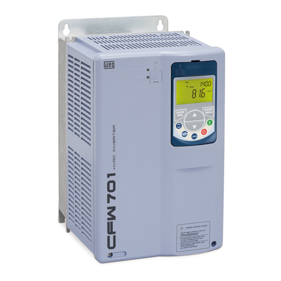
WEG bacnet CFW701 User Manual
Hide thumbs
Also See for bacnet CFW701:
- Addendum to the programming and troubleshooting manual (7 pages) ,
- Quick setup manual (17 pages) ,
- User manual (191 pages)

Related Manuals for WEG bacnet CFW701


Summary of Contents for WEG bacnet CFW701
- Page 1 Motors I Automation I Energy I Transmission & Distribution I Coatings BACnet CFW701 User’s Manual...
- Page 2 BACnet User’s Manual Series: CFW701 Language: English Document Number: 10000972124 / 02 Publication Date: 09/2016...
-
Page 3: Table Of Contents
Contents CONTENTS CONTENTS ......................... 3 ABOUT THE MANUAL ....................... 5 ABBREVIATIONS AND DEFINITIONS ......................5 NUMERICAL REPRESENTATION ....................... 5 DOCUMENTS ..............................5 INTRODUCTION TO THE SERIAL COMMUNICATION ..........6 INTRODUCTION TO THE BACNET COMMUNICATION ..........7 BACNET MS/TP ..........................8 2.1.1 BACnet MS/TP Message Structure .................. - Page 4 Contents P0761 – BACNET EQUIPMENT INSTANCE – LOW PART ............... 21 P0762 – MAXIMUM MASTER NUMBER ....................22 P0763 – MAXIMUM NUMBER OF MS/TP FRAMES ................. 23 P0764 – I AM TRANSMISSION ........................23 P0765 – NUMBER OF RECEIVED TOKENS....................23 BACNET OBJECT MODELING ..................
-
Page 5: About The Manual
About the Manual ABOUT THE MANUAL This manual provides the necessary information for the operation of the CFW701 frequency inverter using the BACnet protocol. This manual must be used together with the CFW701 user manual. ABBREVIATIONS AND DEFINITIONS ASCII American Standard Code for Information Interchange Programmable Logic Controller Human-Machine Interface Read-only... -
Page 6: Introduction To The Serial Communication
Introduction to the Serial Communication 1 INTRODUCTION TO THE SERIAL COMMUNICATION In a serial interface, the data bits are sent sequentially through a communication channel, or busbar. Several technologies use serial communication for data transfer, including the RS232 and RS485 interfaces. The standards that specify the RS232 and RS485 interfaces, however, do specify neither the format nor the character sequence for data transmission and reception. -
Page 7: Introduction To The Bacnet Communication
Introduction to the BACnet Communication 2 INTRODUCTION TO THE BACNET COMMUNICATION BACnet, acronym for "Building Automation Control Network", is a protocol defined by the ANSI/ASHRAE/ISO Standard 135-2004. The protocol defines a model for building-automation, describing the interaction between devices and systems. The protocol defines: Data and commands structured in an object-oriented model;... -
Page 8: Bacnet Ms/Tp
Introduction to the BACnet Communication BACNET MS/TP In the CFW701, the BACnet protocol was developed using the RS485 standard for the physical and data link layers, called BACnet MS/TP (Master Slave/Token Passing). BACnet MS/TP nodes can be divided into two groups, master nodes and slave nodes, according to the node address range. - Page 9 Introduction to the BACnet Communication HEADER DATA Frame Destination Source 0x55 0xFF Length Length Data type address address Figure 2.4: BACnet Frame Preamble: It is formed by two bytes with the 55h and FFh values respectively. Frame type: The BACnet specification defines eight frame types, from 0 to 7. Frame Types 8 through 127 are reserved for the specification improvement, and from 128 through 255 are reserved for each vendor specific frames.
-
Page 10: Address
Introduction to the BACnet Communication ADDRESS It presents an address range from 0 to 254, where: The range from 0 to 127 is reserved for master or slave nodes; The range from 128 to 254 is used only by slave nodes. ... -
Page 11: Network Connections
NETWORK CONNECTIONS 3 NETWORK CONNECTIONS The CFW701 frequency inverter has a standard RS485 interface. Information about the connection and installation of the inverter to the network is presented below. RS485 3.1.1 RS485 Interface Characteristics The interface follows the EIA-485 standard. ... - Page 12 NETWORK CONNECTIONS Enable the termination resistors only at two points, at the extremes of the main bus, even if there are derivations from the bus. CFW701 | 12...
-
Page 13: Inverter Programming
Inverter Programming 4 INVERTER PROGRAMMING Next, only the CFW701 frequency inverter parameters related to the BACnet communication will be presented. SYMBOLS FOR THE PROPERTIES DESCRIPTION Read-only parameter Parameter that can be changed only with a stopped motor Parameter visible on the HMI if the inverter has the network interface installed – RS232, RS485, CAN, Anybus-CC, Profibus –... -
Page 14: P0310 - Serial Baud Rate
Inverter Programming P0310 – SERIAL BAUD RATE Range: 0 = 9600 bits/s Default: 1 1 = 19200 bits/s 2 = 38400 bits/s 3 = 57600 bits/s Properties: Access groups via HMI: Description: It allows programming the baud rate for the serial communication interface, in bits per second. This baud rate must be the same for all the devices connected to the network. -
Page 15: P0314 - Serial Watchdog
Inverter Programming Table 4.1: P0313 options Options Description 0 = Inactive No action is taken and the drive remains in the existing status. A stop command with deceleration ramp is executed and the 1 = Disable via Run/Stop motor stops according to the programmed deceleration ramp. The drive is disabled by removing the General Enabling and the 2 = Disable via General Enable motor coasts to stop. -
Page 16: P0680 - Status Word
Inverter Programming P0680 – STATUS WORD Range: 0000h to FFFFh Default: - Properties: Access groups via HMI: Description: It allows the device status monitoring. Each bit represents a specific status: Bits Function Table 4.3: P0680 parameter bit functions Bits Values Bit 0 Reserved. -
Page 17: P0681 - Motor Speed In 13 Bits
Inverter Programming 0: The fast stop command is not active. Bit 4 1: The drive is executing the fast stop command. Active quick stop This bit is mapped in the BV4 object 0: The drive is configured to use the first ramp values, programmed in P0100 and P0101, as the motor acceleration and deceleration ramp times. -
Page 18: P0682 - Serial Control Word
Inverter Programming → motor speed = 0 P0681 = 0000h (0 decimal) P0681 = 2000h (8192 decimal) → motor speed = synchronous speed Intermediate or higher speed values in rpm can be obtained by using this scale. E.g. for a 4 pole motor and 1800 rpm of synchronous speed if the value read is 2048 (0800h), then, to obtain the speed in rpm one must calculate: 8192 =>... -
Page 19: P0683 - Serial Speed Reference
Inverter Programming 0: The drive uses the first ramp values, programmed in P0100 and P0101, as the motor acceleration and deceleration ramp times. Bit 5 1: The drive is configured to use the second ramp values, programmed in P0102 and P0103, as the Second ramp motor acceleration and deceleration ramp times. -
Page 20: P0695 - Digital Output Setting
Inverter Programming This parameter is mapped in the ANV17 object. P0695 – DIGITAL OUTPUT SETTING Range 0000h to 001Fh Default: 0000h Properties: Access groups via HMI: Description: It allows the control of the digital outputs by means of the network interfaces (Serial, CAN, etc.). This parameter cannot be changed via HMI. -
Page 21: P0760 - Bacnet Equipment Instance - High Part
If the values of parameters P0760 and P0761 are set 0 (default value), the inverter will automatically create the BACnet instance based on the vendor BACnet ID (WEG BACnet ID = 359) and the serial address. For this configuration, the user must only inform the serial address at the parameter P0308. -
Page 22: P0762 - Maximum Master Number
Inverter Programming BACnet instance = BACnet ID + Serial address Example 1: serial address = 102 Instance = 359102 Example 2: serial address = 15 Instance = 359015 NOTE! The instance created automatically is not showed at the parameters P0760 and P0761, which remain with the value 0. -
Page 23: P0763 - Maximum Number Of Ms/Tp Frames
Inverter Programming the address range, hindering the data exchange cycle and the entrance of new devices in the network. By limiting the longest address accepted, addresses above this value are ignored, preventing the search for unnecessary addresses and optimizing the communications. It is recommended that the devices on the network be addressed in sequence from address 1 on, and that this parameter be set with the same value as the last address of the network. -
Page 24: Bacnet Object Modeling
BACnet Object Modeling 5 BACNET OBJECT MODELING A BACnet object represents physical or virtual equipment information, as a digital input or parameters. The CFW701 presents the following object types: ANALOG INPUT; ANALOG OUTPUT; ANALOG VALUE; BINARY INPUT; ... -
Page 25: Cfw701 Bacnet Objects
BACnet Object Modeling Object Type – 10 bits Object instance– 22 bits The Object Type values are defined by the BACnet specification, and object instance is defined by the manufacturer for each object available for communication. Each object can present one of the following access types: Read-only Commandable object. -
Page 26: Mbox
BACnet Object Modeling ANV8 Internal Air Temp Temperature of the internal air – P0034 °C ANV9 Time Powered Number of inverter powered hours – P0042 ANV10 Time Enabled Number of inverter enabled hours – P0043 ANV11 kWh Output Energy Counter of the output KWh – P0044 ANV12 Present Alarm Present alarm –... -
Page 27: Binary Output (Bout) Object
BACnet Object Modeling 5.1.5 BINARY OUTPUT (BOUT) OBJECT It represents a physical digital output that can have its status changed by the controller. CFW701 BINARY OUTPUT type objects are described in the Table 5-6. Table 5-6: BINARY OUTPUT objects Object Access Object name Description... -
Page 28: Device Object
BACnet Object Modeling Table 5-9: Parameter P0682 BINARY VALUE objects Object Access Object name Description Active/inactive Identifier type Run/stop BV16 Run/Stop ON/OFF (P0682 parameter BIT 0) General enable BV17 General Enabling ON/OFF (P0682 parameter BIT 1) Speed direction BV18 Direction of Rotation ON/OFF (P0682 parameter BIT 2) BV19... - Page 29 BACnet Object Modeling 1. Inform the parameter number in the ANV100 object Present Value property; 2. Inform the value to be written in the parameter in the ANV101 object Present Value property. The value to be written must be an integer, without the decimal point representation. E.g., 20.0 must be written as 200 in the MBOX.
-
Page 30: Faults And Alarms Related To The Serial Communication
Faults and Alarms Related to the Serial Communication 6 FAULTS AND ALARMS RELATED TO THE SERIAL COMMUNICATION A128/F228 – TIMEOUT FOR SERIAL COMMUNICATION Description: It is the only alarm/fault related to the serial communication indicates that the equipment stopped receiving valid serial telegrams for a period longer than the one programmed in P0314. - Page 31 WEG Drives & Controls - Automação LTDA. Jaraguá do Sul – SC – Brazil Phone 55 (47) 3276-4000 – Fax 55 (47) 3276-4020 São Paulo – SP – Brazil Phone 55 (11) 5053-2300 – Fax 55 (11) 5052-4212 automacao@weg.net www.weg.net...
Need help?
Do you have a question about the bacnet CFW701 and is the answer not in the manual?
Questions and answers