Table of Contents
Advertisement
Quick Links
w w w . v o l t e c h . c o m
Voltech Instruments Inc.
11637 Kelly Road
Suite 306
Fort Myers FL 33908, U.S.A.
Tel: 239 437 0494
Fax: 239 437 3841
sales@voltech.com
V
AT
U
OLTECH
I
SER
U
SER
M
ANUAL
AT
AT
AT
AT
i i i i
M
ANUAL
Voltech Instruments Ltd.
Harwell International Business Centre
Didcot, Oxon OX11 ORA, U.K.
Tel: +44 (0) 1235 834555
Fax: +44 (0) 1235 835016
th
148 6
Street
sales@voltech.co.uk
P
I
AGE
Advertisement
Chapters
Table of Contents

Related Manuals for Voltech ATi


Summary of Contents for Voltech ATi
- Page 1 . v o l t e c h . c o m i i i i ANUAL Voltech Instruments Inc. Voltech Instruments Ltd. 11637 Kelly Road 148 6 Street Suite 306 Harwell International Business Centre Fort Myers FL 33908, U.S.A.
- Page 2 Voltech Instruments. Voltech Instruments 2002-2005. All rights reserved. The Voltech ATi is protected by the following patents: USA: US 5500598 2261957B Europe:...
- Page 3 DANGER OF ELECTRIC SHOCK Only qualified personnel should install this equipment, after reading and understanding this user manual. If in doubt, consult your supplier. RISQUE D'ELECTROCUTION L'installation de cet équipement ne doit être confiée qu'à un personnel qualifié ayant lu et compris le présent manuel d'utilisation.
-
Page 4: Table Of Contents
1.5 ATi Features Summary ................. 1-11 1.6 Typical Production Installation............... 1-12 1.7 Using the ATi for Design and Evaluation............1-14 1.8 Overview ....................... 1-15 1.9 How Does the ATi Tester Run a Test?............1-26 2 Getting Started..................2-1 2.1 Introduction ..................... 2-5 2.2 Installation..................... 2-10 2.3 Quick Start Tutorial .................. - Page 5 4.4 License Registration..................4-50 ....................5-1 IXTURES 5.1 Introduction ..................... 5-5 5.2 Description ...................... 5-6 5.3 Fixture System Specification ................. 5-12 5.4 Fixture Parts Available from Voltech ............. 5-13 5.5 Kelvin Connections..................5-18 .................6-1 RONT ANEL ODES 6.1 LCR Mode Basic Functions................6-5 6.2 Tests Available in the LCR Modes ..............
- Page 6 9.1 Warranty ......................9-5 9.2 Limitation of Warranty ..................9-5 9.3 Service and Calibration ................... 9-6 9.4 Obtaining Service and Applications Support ........... 9-6 9.5 Firmware Upgrades..................9-7 10 INDEX....................10-1 OLTECH ANUAL...
-
Page 7: Introduction
Thank you for choosing to use this Voltech product. If you experience any difficulty during installation or use of the ATi or are unsure of any of its features or abilities, please do not hesitate to contact either your local supplier or a Voltech main service centre as listed inside the front cover. - Page 8 NTRODUCTION OLTECH ANUAL...
- Page 9 NSTRUCTIONS 1.3. AT AT3600..................1-7 I AND 1.4. T ..................1-8 ESTS UPPLIED 1.4.1. Standard Program Tests................1-8 1.4.2. Optional Program Tests................1-8 1.4.3. ATi LCR Mode Functions................. 1-9 1.5. AT ..............1-11 EATURES UMMARY 1.6. T .............1-12 YPICAL RODUCTION NSTALLATION 1.7. U ........1-14...
- Page 10 NTRODUCTION OLTECH ANUAL...
-
Page 11: How To Use This Manual
Voltech reserves the right, however, to change the operation or specification of the ATi without notice. No liability is accepted for the inappropriate, negligent, or incorrect set-up of the ATi by the user, by either manual or automated means. OLTECH... -
Page 12: General Safety Instructions
1.2 G ENERAL AFETY NSTRUCTIONS WARNING: The ATi must be connected to a safety ground (earth). Only insert the power lead into a socket with a protective ground contact. Ensure that the power lead is in good condition and free from damage before use. -
Page 13: Ati And At3600
1.3 AT AT3600 I AND The ATi is one of a family of automatic testers from Voltech that share the same fixture construction and PC Editor and Server software. ATi’s and AT3600’s can share the same Server application, simultaneously recalling test programs and recording test results. -
Page 14: Tests
NTRODUCTION 1.4 T ESTS UPPLIED At the time of printing, the following tests are available for the ATi: 1.4.1 Standard Program Tests Continuity DC resistance AC resistance – series circuit AC resistance – parallel circuit Inductance – series circuit Inductance – parallel circuit Inductance –... -
Page 15: Ati Lcr Mode Functions
Frequency response RESP Trim adjustable part TRIM User port relay control Inductance – series circuit with external bias LSBX Inductance – parallel circuit with external bias LPBX 1.4.3 ATi LCR Mode Functions Measurement Symbol Units Display Units Ω DC resistance Ohms Ω... - Page 16 NTRODUCTION To determine which options were installed on your tester during manufacture, check the list attached to the calibration certificate shipped with your ATi. 1-10 OLTECH ANUAL...
-
Page 17: Ati Features Summary
NTRODUCTION 1.5 AT EATURES UMMARY The ATi tester is a fast, accurate and versatile automatic LCR meter. FAST – Typically more than 10 DIFFERENT tests per second. • 20 way switch matrix. • Automatically switches from making measurements on one winding of a transformer to another winding. -
Page 18: Typical Production Installation
NTRODUCTION The ATi is very easy to use. However, it is a complex instrument, which can be installed and operated in many ways. In order to maximize the benefits that the ATi can bring to your test environment, please study the following section carefully. - Page 19 NTRODUCTION Test Program Creation • Simple, easy to use, Windows based Editor for creating test programs. (Chapter 3). • Requires no software programming skills or expertise. • Test conditions may be entered manually, or chosen automatically by measuring a sample transformer. Program Archive ~ Management •...
-
Page 20: Evaluation
NTRODUCTION 1.7 U SING THE I FOR ESIGN AND VALUATION • Tests: L, C, Z, D, Q, Rac, X, Z, θ, Rdc, Insulation Resistance, Turns Ratio, Leakage Inductance. Bias current up to 1A. • Fully programmable (5V, 3MHz) or AUTOMATIC test conditions. •... -
Page 21: Overview
NTRODUCTION 1.8 O VERVIEW This section gives a more detailed overview of your ATi and how to use it. It is recommended that you read this section before attempting to use your tester. Topics covered in this overview: • The features and functionality of the ATi in a production environment. -
Page 22: Creating Programs - The Editor
NTRODUCTION 1.8.1 Creating Programs - The Editor The test program is, simply, the list of tests that you wish to apply to your transformer. Individual transformers will each have their own program, but as an example, a typical program for a three winding switch-mode power supply transformer could be as follows: Program: Resistance... -
Page 23: Storing Programs And Results - The Server
‘production’ use. This is the function of a second PC program supplied with your ATi called the Server. Usually, the Server would be installed on a PC with access to a large disk that could be attached to the PC itself, or connected via a network. -
Page 24: Transferring Programs Between Editor And Server
NTRODUCTION 1.8.3 Transferring Programs between Editor and Server Within your test environment there are several possible ways in which the Server and Editor may be installed and used, depending on how many separate PC’s are available. Programs Server port Auxiliary port The standard installation uses separate PC’s for the Editor and Server: Transferring a new test program from the Editor to the Server archive can be done in any of three ways:... - Page 25 NTRODUCTION With both Server and Editor installed on the same PC, transferring a new test program from the Editor to the Server archive can be done in either of two ways: • Via the tester (if the auxiliary port connection is made). •...
-
Page 26: Executing Programs
NTRODUCTION 1.8.4 Executing Programs Large Production Facility The standard installation in a large production facility could use several testers, together with a Server PC for test program and results archive: Programs/ Programs/ Programs/ Results Results Results Server Advantages • Convenient storage and management of large numbers of test programs (e.g. - Page 27 NTRODUCTION Limitations • Requires the Server PC to be permanently connected. This is to allow the tester uninterrupted access to the Server, for the purposes of accessing programs and storing results. • Usually requires an additional PC (which could be a portable) to be attached locally to (the auxiliary port of) one of the testers when a new program needs to be developed and evaluated.
- Page 28 NTRODUCTION Small Production Facility At the other extreme and possibly more suitable for a small production facility with a single AT series tester and limited or temporary access to a PC: Connect the AT to the PC (running both Editor and Server software) as shown above when developing the test programs.
-
Page 29: Test Fixtures
NTRODUCTION 1.8.5 Test Fixtures When running the test program in production, how do you connect your transformer with its own arrangement of terminals to the test nodes of the AT Series Tester? The AT Series of transformer testers has been designed with its own test fixture system to answer just this question: •... -
Page 30: Operating The At Series Testers In Production Test
NTRODUCTION 1.8.6 Operating the AT Series Testers in Production Test The ATi is suitable for use in both manual and robotic production situations. Manual Use – Testing Smaller Batches of Different Transformers: Operator: Chooses transformer part number from a list or swipes a barcode... - Page 31 In robotic situations, the tester's remote port provides the digital inputs and outputs for connecting into your system: Remote PC records all test data for statistical analysis using Run/Stop/Fail/Busy Voltech server software signals for process control Good parts for further processes...
-
Page 32: How Does The Ati Tester Run A Test
Circuits Processors Keyboard, Display and Interfaces The ATi consists of the following 7 basic functional blocks: Relay Switching Matrix The relay switching matrix is used to connect the selected test source and measurement circuits to the particular nodes required in the test. - Page 33 NTRODUCTION Test Sources The three sources are fully programmable in thousands of steps of voltage, current and frequency. Measurement Circuits Fully auto-ranging, the measurement circuits are capable of measuring from µV and nA to 500V and 4Apk with great precision. Keyboard, Display and Interfaces A broad range of programming, results display and storage methods.
- Page 34 NTRODUCTION As an example, the sequence for measuring inductance may be summarized below: Select Nodes Set-up Source Select Type (Relay Switching) Frequency Of Source Ramp-up Source Voltage Change Source Measure V & I Voltage Harmonic Analysis Signal Level Correct? Ramp-down Compare With Calculate Test Limits...
-
Page 35: Getting Started
2 Getting Started OLTECH ANUAL... - Page 36 ETTING TARTED OLTECH ANUAL...
- Page 37 TARTED Contents – Getting Started 2.1. I ..................2-5 NTRODUCTION 2.1.1. Package Contents ..................2-6 2.1.2. The ATi Front Panel ..................2-7 2.1.3. Other Data Inputs ..................2-9 2.2. I ..................2-10 NSTALLATION 2.2.1. Switching on the ATi.................. 2-10 2.2.2. Installing the PC Editor................2-12 2.2.3.
- Page 38 ETTING TARTED 2.9. S ..................2-77 2.9.1. Set-up Softkey................... 2-78 AT Password....................... 2-83 Resetting Tester Set-Up Options ................ 2-83 2.9.2. Groups Softkey ..................2-84 OLTECH ANUAL...
-
Page 39: Introduction
TARTED 2.1 I NTRODUCTION This chapter is designed to introduce you to the basic facilities of the ATi and help you to realize the benefits of automated transformer testing in the shortest possible time. If you are reasonably familiar with the testing of transformers and how to install... -
Page 40: Package Contents
Editor and Server installation files and other important information • Calibration certificate • Product registration information Please report any missing items to your Voltech supplier. Returning your product registration card will ensure that you continue to receive the latest product and application information. OLTECH ANUAL... -
Page 41: The Ati Front Panel
BNC connectors FAIL Indicator The front panel of the ATi is mounted towards of the rear of the fixture bay to allow easy access for loading transformers and to avoid accidental damage to the display and keys. The main features are as follows:... - Page 42 PASS or FAIL as desired. Logic level signals representing the RUN, PASS, FAIL and BEEP actions are available on the REMOTE port at the back of the ATi for use with automatic handling equipment and external indicators.
-
Page 43: Other Data Inputs
To give you the greatest ergonomic flexibility, methods other than the keyboard can be used to initiate testing and enter data. Run-pads Two stainless steel discs, at the front of each side of the ATi. Lightly touching the programmable run-pads will start the programmed test sequence. Footswitch The ‘Run’... -
Page 44: Installation
You must connect the power lead to a socket with a safety ground contact. When the ATi tester is switched on it performs a self-test, which lasts for about 10 seconds. During power-on self-test, you will see on information concerning your ATi’s configuration on the display, including the firmware version. - Page 45 Self-Test A detailed explanation of the operation of the ATi that follows pressing the Execute, Program and Self-Test keys is given later in this chapter. 2-11 OLTECH...
-
Page 46: Installing The Pc Editor
Connect the tester's auxiliary port to a spare COM port on the PC as shown. The type of connector on the PC will determine the cable that you use. For most PC’s this will be a 9-pin female (PC) to 9-pin female (ATi). Auxiliary port... - Page 47 PC COM Port Configuration When the installation of the Editor has been completed, you will see the Editor icon in the program group ‘Voltech Software’. Double-click with the left mouse button on the Editor icon to start the program. Initially, configure the Editor to use the chosen COM port: From the top-level ‘Setup’...
-
Page 48: Installing The Pc Server
Editor. The Server is often installed on a different PC to that which will be used for the Editor, depending on your production needs. A Server PC needs to be permanently connected to the ATi only if you wish to store test results or use a central program store rather than the ATi’s own memory. - Page 49 ETTING TARTED Programs/ Programs/ Programs/ Results Results Results Before installing an expansion card, ensure that the PC is switched off and that you follow all of the manufacturer’s instructions. All supporting software must also be installed before attempting to configure the Server application. The same server program is used for all AT Series Testers (excluding the discontinued AT3500 and AT1000).
- Page 50 Server Software Set-up When the installation of the Server has been completed, you will see the Server icon in the program group ‘Voltech Software’. Double-click with the left mouse button on the Server icon to start the program. Before you can use the Server, the PC communication channels must be assigned for each tester connected.
- Page 51 ETTING TARTED When the Server is executed for the first time, the following dialogue will be displayed: A check box 'Do not display this dialogue at Startup' exists to prevent it from being displayed each time the Server application is launched. When this option is activated, this dialogue box can be accessed via the ‘Setup’, ‘Communications...’...
- Page 52 ETTING TARTED The final stage of setting up the server involves specifying the file location paths. The directory set-up dialogue will prompt you with the current directory. Change these settings if you wish to nominate your own program and results storage directories.
-
Page 53: Quick Start Tutorial
UTORIAL 2.3.1 Introduction After you have installed your ATi and its associated Editor and Server PC software packages as described in the previous section you may wish to follow through this tutorial before trying to create any programs for actual use. -
Page 54: Drawing The Transformer Schematic
ETTING TARTED 2.3.2 Drawing the Transformer Schematic At the PC, double-click on the editor icon to start the PC Editor. The first thing to do is to ‘draw’ a schematic of the transformer to be tested. Using the left mouse button, click on ‘Schematic’ on the top Level menu bar, and select ‘Add Winding’... - Page 55 ETTING TARTED Repeat steps 1-3 to create a second winding. This time place the winding on the right hand side of the screen, a mirror image of the first winding, and use different terminal names (e.g. ‘C’ and ‘D’). The screen should then look like this: Now you must connect the windings to the test nodes of the tester: Place the mouse pointer over terminal A;...
-
Page 56: Creating The Test Program
ETTING TARTED 2.3.3 Creating the Test Program After creating the transformer schematic, you may now create an example program, containing the following four tests: Resistance of winding AB (59 to 73Ω) Resistance of winding CD (59 to 73Ω) Inductance of winding AB (>3H) (1:1 ±... - Page 57 ETTING TARTED By clicking with the mouse, enable the following option ‘Send Results to Server’ In the Fixture ID box, enter the name: ‘UNIVERSAL’ Click on ‘OK’ or press [Return] to accept and close the dialogue box. You can now move on to create the program: From the top-level ‘Program’...
- Page 58 ETTING TARTED The following dialogue box will appear. Initially enter the terminal names. Input ‘A’ as the high terminal and ‘B’ as the low terminal, moving between the fill-in boxes using the TAB key. Click anywhere over the High and Low Terminal drop-down boxes to see a list of the available terminals.
- Page 59 ETTING TARTED If the "User Offset Enabled" check box is checked, a value can be entered into the edit box. The value entered (in the units shown) is then added to any results returned from the AT tester. This function can be used to adjust for measurement fixture effects that cannot be compensated for or to compensate the fixture manually so a compensation stage is not required to obtain the correct readings.
- Page 60 ETTING TARTED High terminal C Low terminal D Minimum 59Ω Maximum 73Ω Click on the ‘OK’ button. Again, the test and its parameters will appear in the ‘Program’ window. Now, by double-clicking the left mouse button, select ‘LS Inductance (Series Circuit)’ from the ‘Available Tests’ window. At the dialogue box, enter the data required for the inductance test: Signal 1V (again, choose the V units button by clicking...
- Page 61 ETTING TARTED The "User Offset Enabled" check box has the same function as before but in units of inductance. Click on the ‘OK’ button. Again, the test and its parameters will appear in the ‘Program’ window. Finally, by double-clicking the left mouse button, select ‘TR Turns Ratio’...
- Page 62 ETTING TARTED Click on the ‘OK’ button. Again the test and its parameters will appear in the ‘Program’ window. 2-28 OLTECH ANUAL...
- Page 63 ETTING TARTED The lower-left window should now contain the complete program. The scroll bars in this window enable you to view each test in the program in turn to check that it is correct. The Editor will not allow a program to be run in the AT unless it has previously been saved: From the top-level menu bar, select Part >...
-
Page 64: Running The Program From The Editor
ETTING TARTED At the dialogue box, type in TUTORIAL as the part name Click on the OK button to close the dialogue box and save the test program in the Editor default directory. 2.3.4 Running the Program from the Editor The following section describes how to run a test program from the Editor. - Page 65 ETTING TARTED Before proceeding further, make sure that the interface cable between the tester's Auxiliary Port and the selected PC COM port is correctly fitted, and that the COM Port is correctly configured in the editor (see page 2.14). Ensure that the tester has been switched on. To run the program: From the top-level menu bar, select: Tester >...
- Page 66 8, 9, and 10 then the results might be: If no transformer is fitted, the results will have no meaning, but you have now successfully installed the ATi and the Voltech AT Editor software. The results window will give you the options to: Print the test results.
-
Page 67: Server Quick Start
2.3.5 Server Quick Start Transferring the Program to the Server The Voltech Server software is supplied with every AT Series Tester. The use of the Server software is required for handling and storage of test results and is recommended for handling large numbers of different test programs. - Page 68 ETTING TARTED To transfer the program, from the top-level menu bar, select: Server > Download Program The Editor will now download the test program to the Server using the AT. After a few seconds, you should see a message to say that the Download was successful.
- Page 69 ETTING TARTED At the dialogue box, type in the part name TUTORIAL as before, and change the directory to the one selected for program storage e.g. C:\AT3600\SERVER when the Server was installed. Click on the OK button to close the dialogue box and save the test program in the Server program directory.
-
Page 70: Running A Program On The Tester
ETTING TARTED 2.3.6 Running a Program on the Tester Having stored the program in the Server archive, it is now possible to run the program on any AT that is connected to the Server. Before proceeding further make sure that the Server is running, with the interface cable correctly fitted between the tester’s server port and the selected Server PC COM port, and the COM port is correctly configured in the Server software. - Page 71 ETTING TARTED Use the following sequence of key presses to ensure that the AT is configured to use the Server as the source for test programs: From the top-level menu, choose ‘Set-Up’ to change to the following display: Press the softkey ‘Set-Up’ and at the following display: Press the ↓...
- Page 72 ETTING TARTED If, as shown above, the origin is INTERNAL, then press the softkey ‘Server’, so that the third line reads as follows: Press the softkey EXIT to return to the ‘Set-Up’ display and then press the EXIT softkey, again, to return to the top-level display. 2-38 OLTECH ANUAL...
- Page 73 ETTING TARTED Then, use the following sequence of key presses to run the test program for the part ‘TUTORIAL’: Press the softkey ‘Programs’ to display: The program name can now be chosen from the list of programs available on the PC Server. If the list of programs fails to appear after a few seconds, check that the AT Server is running, the COM port and file folder are configured correctly and that the cable from the AT Server port is correctly fitted to the PC.
- Page 74 ETTING TARTED When the download has been successfully completed, you will see a message to fit the fixture similar to the following: As the fixture is already fitted, and compensation is not required with the sample transformer, simply press the ‘No Comp’ softkey to move on to the ‘Run-Finish’...
- Page 75 ETTING TARTED Press the ‘Run’ softkey to start program execution. As the program is running, the RUN indicator (the yellow LED to the left of the display) will be illuminated, and the display will indicate the test currently being executed: At the end of program execution, the PASS indicator (the green LED to the left of the display) should be illuminated, and the display should show: 2-41...
- Page 76 ETTING TARTED Press the RUN softkey several times to repeat the program execution. On each run of the program, the test results should be passed back to the Server, where they may be viewed in the ‘On-line Monitor’ window If batch statistics have been enabled within the Server, you will see the summary batch results window.
- Page 77 ETTING TARTED Test results may also be reviewed at any time via the tester’s front-panel results listing screen, which is accessible from the ‘Run-Finish’ display by pressing the ‘Results’ softkey (see below). The results listing screen displays all completed tests giving test number, type, result in both value and pass or fail, and status error (for a description of status error codes, see chapter 3).
- Page 78 This is the end of the step-by-step tutorial, which forms only a very brief introduction to the features available on your ATi. Please study and browse through the rest of this manual (or the on-line help for the Windows software) to get the best from your transformer tester.
-
Page 79: Storing Programs
Method 1: Using a permanently connected PC server has been described in the previous ‘Getting Started’ section. Method 2: Using the ATi’s own internal memory as described here: The programs can be stored within the tester even when it is switched off. - Page 80 ‘Programs’ at the top-level display, choose the program from the list of programs and press the ‘Run’ key and continue as before. Storing Groups of Programs Inside the ATi Using the PC Server Rather than dealing simply with individual programs, the AT Server allows you to create groups of programs, which may be downloaded to the AT tester and then used individually from within the local tester facilities.
- Page 81 ETTING TARTED On the tester, at the top-level display, choose ‘Set-Up’. Then, at the ‘Set-up’ display, press the ‘Groups’ softkey , followed by the ‘List’ softkey to obtain a list of program groups available for download. Select the group to be downloaded to the tester and press ‘Enter’. If the group download is completed successfully, you will see the following display: 2-47 OLTECH...
- Page 82 ETTING TARTED At this point, unless you wish to archive measured results on the Server, the Server connection may be removed. Return to the tester’s top-level display by pressing the ‘Continue’ softkey, change the set-up of the tester to use the internal program store instead of the Server, press the ‘Programs’...
-
Page 83: Self-Test
ETTING TARTED 2.4 S Self-test is a sequence of checks made by the tester to ensure the unit is functioning correctly. Self-test checks that all of the relays in the 20-way matrix are opening and closing properly and checks that all the test signal sources and measuring circuits are working properly and within their calibration limits. - Page 84 ETTING TARTED As the self-test is running, the front-panel display will indicate progress using a horizontal bar: At the end of the self-test, you should see the following screen: 2-50 OLTECH ANUAL...
- Page 85 In the unlikely event that your tester continues to fail, please make a careful note of the failure message and error codes, which may be accessed by pressing ‘Details’ at the above display, and contact your Voltech supplier immediately. (For more detail on AT error codes, see chapter 3.)
-
Page 86: Production Mode
TARTED 2.5 P RODUCTION This is the normal operating mode of the ATi when used for production testing of transformers. Before you try to use the tester in production mode, make sure that all of the following have been carried out: 1. -
Page 87: Production Mode With No Options Enabled
ETTING TARTED 2.5.1 Production Mode With No Options Enabled For simple test programs, (where Top-level none of the following options are Display enabled: batch number, operator number or serial number), the flow diagram shown on the left Select summarizes production mode Programs Soft-key operation. - Page 88 The program to be run may now be chosen from a list of programs available on the PC Server or in the ATi’s own memory (i.e., local programs), entered by swiping a barcode, or created directly from the front panel by selecting ‘* New program *’...
- Page 89 ETTING TARTED FIXTURE1 is the name given as the ‘Fixture ID’ in the Editor software ‘Program options’ dialogue (see chapter 3) or under program options in front- panel program mode (see chapter 6). Press ‘Compensate’ or ‘No Comp’ as required. Note: For fixture compensation, see later in this chapter.
-
Page 90: Error Messages
ETTING TARTED After the measurement, remove the component and place it in the ‘Pass’ or ‘Fail’ bin, as appropriate. Continue in this way until each component in the batch has been tested, then press ‘Finish’. 2.5.2 Error Messages Server Program Store Error Possible Causes: Faulty cable The cable from the AT Server port to the Server PC has a broken wire or is not... - Page 91 ETTING TARTED If the Server software and connection to the Server PC are working correctly, the following error screen may appear: Cause: The directory set up in the Server application as the location of test programs does not contain a test program file with the requested name. Local Program Store Error 2-57 OLTECH...
-
Page 92: Indications Displayed While Tests Are Running
ETTING TARTED Cause: The requested part number is not resident in the group of programs that have been downloaded into the AT. At all the above displays, pressing the ‘Continue’ softkey will take you back to the top-level display. 2.5.3 Indications Displayed While Tests Are Running Where ‘1’... - Page 93 ETTING TARTED The ‘Run-Finish’ display is seen after a component has been tested. The front- panel LED (green = ‘Pass’, red = ‘Fail’), the output lines of the remote port and the LCD indicate the pass or fail result of the previously tested transformer, so that the operator may place it in the appropriate ‘Pass’...
-
Page 94: Re-Measuring Fixture Compensation
If the STOP softkey is pressed or the STOP input of the remote port is held low, the ATi will immediately stop testing. STOP will be shown on the display, all LED’s will be off, and no results will be reported back to the Server. -
Page 95: Execute Mode With Options Enabled
Note that these options are part of the program, not global settings of the ATi, allowing you to enable different options for each transformer, as required. - Page 96 ETTING TARTED When running programs with any of the above options enabled, there will be additional displays (depending on which options are enabled) after the ‘Fit the Fixture’ display and before the RUN-FINISH display. 2-62 OLTECH ANUAL...
- Page 97 ETTING TARTED The following flow diagram summarizes the possibilities: Top-level Display Select Programs Soft-key Select Test Program to Run Fit and Compensate Fixture Enter Operator Name Enter Batch Number Enter Serial Number New Batch RUN-FINISH New Operator Menu Re-compensate FINISH Measurements Enter New Serial Number...
- Page 98 ETTING TARTED Additional displays after entering the part number 2-64 OLTECH ANUAL...
- Page 99 ETTING TARTED Use either the keypad or a barcode reader to enter the operator/batch/serial number, then press the ENTER key on the keypad or the ‘Enter’ softkey. Cursor softkeys ( ← → ) appear in context, and may be used with the ‘Delete’ softkey to correct mistakes.
- Page 100 ETTING TARTED If the next serial number to be used simply follows on in sequence after the previous one, then press the ‘Last + 1’ softkey (or the touch pads). This will enter the next serial number automatically and return the display to the RUN- FINISH selection.
- Page 101 ETTING TARTED (Again, cursor softkeys ( ← → ) appear in context, and may be used with the ‘Delete’ softkey to correct mistakes.) Note: Pressing the ‘Abort’ softkey will also take you back to the RUN-FINISH display, but with no serial number entered. This would be the correct action if the next softkey you wish to press is FINISH.
- Page 102 ETTING TARTED 2-68 OLTECH ANUAL...
-
Page 103: Stop On Fail
ETTING TARTED 2.6 S TOP ON ‘Stop on Fail’ is another program option that is either enabled or disabled when the program is created (see chapter 3). When enabled, it will cause the measurements to be terminated after each test that has produced a ‘Fail’... - Page 104 ETTING TARTED Note The third line, showing the graphical comparison of the measured value and test limits, has a logarithmic scale. The measured value may be represented by either a vertical bar (as shown), when it lies within the range that can be displayed on the LCD, or by an arrowhead (<...
-
Page 105: Trim
ETTING TARTED 2.7 T If the TRIM test is included in a program, the behavior in production mode is similar to the ‘Stop on Fail’ option described above: If the test before the TRIM test produces a ‘Pass’ result, then the program proceeds directly to the next test after the TRIM test. - Page 106 ETTING TARTED Note After making the necessary adjustments, you must press ‘Re-Run’ to enable the component to be recorded as a ‘Pass’. If further adjustment is necessary, you may re-run from the start as many times as you like. Unless the option ‘Send Retry Results to Server’ is enabled, there will be no data sent back to the Server until the measurements for all tests in the program have been completed.
-
Page 107: Fixture Compensation
ETTING TARTED 2.8 F IXTURE OMPENSATION The AT’s fixture compensation eliminates errors due to stray parasitic components on the fixture board itself. These are usually a combination of parallel capacitance between adjacent wires, sockets or pins, and series resistance and inductance along the lengths of wires. It is best to try fixture compensation when performing trial runs on the program, as it is being developed, using the Editor. - Page 108 ETTING TARTED For S/C compensation, first make up a transformer bobbin with shorting links in place of the windings: To make a shorting bobbin, solder short pieces of wire across the relevant pins (or all of the pins) a spare blank bobbin or complete transformer. Transformer Shorting Bobbin for S/C compensation Put the short-circuit bobbin into the fixture and...
-
Page 109: Getting Started
Press softkey 4 ‘NO COMP’ to abort compensation and begin running the program. Once you have chosen either S/C compensation or O/C compensation, the ATi will make very accurate measurements of the stray components. A typical S/C compensation measurement might take 10 seconds or more during which time... - Page 110 ETTING TARTED Should either S/C or O/C compensation display a FAIL, as shown above, check: • The short-circuit connections (for S/C compensation). • That there are no erroneous short–circuits on the fixture. • That the fixture is properly seated and locked down into the fixture bay.
-
Page 111: Set-Up Mode
ETTING TARTED 2.9 S Set-up mode has two main functions: To change the tester's set-up options (including setting up for Server operation) and to download a group of programs from the Server PC to the tester's internal memory. To access set-up mode from the top-level menu (see above), press the ‘Set- Up’... -
Page 112: Set-Up Softkey
ETTING TARTED The two main functions of set-up mode each have their own softkeys at this display. Press the ‘Groups’ softkey to download a group of test programs from the Server to the tester's internal memory; or press the ‘Set-Up’ softkey to change any of the tester’s set-up options. - Page 113 ETTING TARTED The full list of options is shown below: SHORT CONTINUOUS Fail Beeper SHORT Pass Beeper CLICK BEEP Key Response CHANGE Beeper Volume CHANGE Display Contrast LIGHT DARK Display Background Clock: → yyyy mmm dd hh:mm L AND R L OR R L ONLY R ONLY...
- Page 114 ETTING TARTED Beeper Volume Pressing the softkey ‘Change’ brings up an additional display: Press the ↑ and ↓ softkeys until the beeper makes the level of sound you require, then press the EXIT softkey to return to the set-up list. Display Contrast The additional option display is very similar to the beeper volume display, again with ↑...
- Page 115 For optimum measurement accuracy in LCR mode using the BNC leads, calibration factors are stored within the ATi. This calibration is set at the factory for the BNC leads supplied with the ATi and it is not normally necessary to adjust this calibration.
- Page 116 ETTING TARTED • Press 'Continue', short together nodes 13 and 15 on the fixture and press 'Continue' again to make the first measurement which is a short-circuit compensation. • Next remove the short, but ensure that the power and sense terminals are short-circuited together on nodes 13 and 15.
-
Page 117: At Password
ETTING TARTED AT Password Pressing the ‘Change’ softkey, brings up the following display: Enter the new AT password via the instrument keypad, using the ‘Shift’ softkey to activate letter entry, if necessary. Press ‘Enter’ to confirm the new password. Resetting Tester Set-Up Options Please note that pressing the decimal point (“.”) on the instrument keypad 2-83 OLTECH... -
Page 118: Groups Softkey
ETTING TARTED during boot-up at the general information screen will reset all tester options to the factory defaults, including screen contrast, screen background and beep volume, excluding the real-time clock. The factory default settings are: Option Default Setting FAIL Beeper PASS Beeper Key Response CLICK... - Page 119 As with other names, the group name can now be typed in from the keypad, entered using a bar-code reader connected to the bar-code port of the ATi, or selected from a list using the ‘List’ option. (Again, the cursor softkeys and the ‘Delete’...
- Page 120 ETTING TARTED Press ‘Continue’ to return to the top-level display. Your program group has now been loaded into the tester’s internal store and the Server PC may be disconnected. These programs will be saved during power off, and will only be overwritten by another group download.
- Page 121 ETTING TARTED Possible Causes: Faulty cable The cable from the tester’s Server port to the Server PC has a broken wire, or is not plugged in correctly. COM port The COM port has not been set up in the Server application. Server not running Either the Server PC is not powered on, or the Server application is not running.
- Page 122 ETTING TARTED disconnected. These programs will be stored during power off, and will only be overwritten by another group download. Tester Download Using The Editor A single program may be stored in the AT using the Editor PC. Once a program has been entered using the Editor and downloaded to the tester, the tester will display: Press ‘Local Save’...
-
Page 123: Program Editor
ROGRAM DITOR OLTECH ANUAL... - Page 124 ROGRAM EDITOR OLTECH ANUAL...
- Page 125 ROGRAM DITOR Contents – Program Editor 3.1.................3-5 REATING A ROGRAM 3.2..........3-6 REATING THE RANSFORMER CHEMATIC 3.2.1............3-7 DDING A RANSFORMER INDING 3.2.2........3-8 ONNECTING THE INDING ERMINALS TO ODES 3.2.3................3-8 ELETING A INDING 3.2.4................
- Page 126 ROGRAM EDITOR 3.5.1..............3-43 RONT PANEL RROR ODES 3.5.2................3-43 DITOR RROR ODES 2.8) SEE ALSO SECTION 3.6......3-46 IXTURE OMPENSATION 3.7............3-48 ROGRAMMING INTS AND OLTECH ANUAL...
-
Page 127: Creating A Program
ROGRAM DITOR 3.1 C REATING A ROGRAM Using the Editor enables you to quickly and easily create test programs for your AT Series Tester without any specialized knowledge of computer programming. The Editor will guide you through the programming of the tests you wish to carry out, helping you ensure that programming errors are eliminated. -
Page 128: Creating The Transformer Schematic
REATING THE RANSFORMER CHEMATIC The Voltech AT Series Schematic Editor allows you to recreate the configuration of the transformer on the fixture as a schematic diagram on the screen. Once the way in which the AT’s nodes are connected to the transformer pins has been entered into this schematic you can create test programs without having to refer to the tester’s node numbers. -
Page 129: Adding A Transformer
ROGRAM DITOR 3.2.1 A DDING A RANSFORMER INDING To add a transformer winding onto the screen: Select ‘Add Winding’ from the Schematic menu on the menu bar. Place the winding on the screen: A selected winding will now be displayed attached to the mouse pointer on the screen. -
Page 130: Connecting Thew
ROGRAM EDITOR 3.2.2 C ONNECTING THE INDING ERMINALS TO ODES To connect the winding terminals to test nodes: 1 Select a terminal to connect with the RIGHT mouse button. 2 Keeping the right button pressed, drag the wire to the selected test node. 3 When the mouse pointer is over the test node, release the mouse button. -
Page 131: Renaming A Terminal
ROGRAM DITOR 3.2.4 R ENAMING A ERMINAL To rename a terminal either: Select the winding containing the terminal to rename by using the mouse pointer and clicking the left mouse button. Choose ‘Rename Terminals’ from the ‘Schematic’ menu OR use the mouse pointer and double click on the chosen winding. -
Page 132: Dding Aerminal To An
ROGRAM EDITOR 3.2.5 A DDING A ERMINAL TO AN XISTING INDING To add a terminal to a transformer winding: Select ‘Add Winding’ from the ‘Schematic’ menu on the menu bar to create a second two terminal winding. Now place the new winding on the same side of the schematic as the winding that requires the additional terminal. -
Page 133: Eleting Aerminal
ROGRAM DITOR 3.2.6 D ELETING A ERMINAL ROM AN XISTING INDING To remove a terminal from a transformer winding: 1. Select the terminal which you would like to be removed by using the mouse pointer and clicking the left mouse button once. 2. -
Page 134: Dding Acreen
ROGRAM EDITOR 3.2.9 A DDING A CREEN ONNECTION To add a screen connection: Choose ‘Add Screen Connection’ from the ‘Schematic’ menu. A connection from the screen will appear on the schematic. You may now add a screen-to-node connection. 3.2.10 D ELETING A CREEN ONNECTION... -
Page 135: Creating The Test Program
ROGRAM DITOR 3.3 C REATING THE ROGRAM This section describes the procedures used when creating the test program with the AT Series Editor. By the end of this section, you will be able to: • Set up the program options •... -
Page 136: Setting The Program
ROGRAM EDITOR 3.3.1 S ETTING THE ROGRAM PTIONS Overview After you have created the program schematic, and before starting to insert any tests in the program, you should set up which program options you would like to use. From the top-level menu bar, select: Program >... - Page 137 ROGRAM DITOR You may now set up any of the following options by simply clicking with the left button of the mouse: Results Printing Printed reports may be obtained from the printer port of the tester as follows: There will be no results printed out during the test execution. The results of the tests producing a ‘fail’...
- Page 138 Exceeding the AQL is an indication that there is a problem with the quality of the production process or the quality of materials that are being used. AQL monitoring is an optional feature of the Voltech PC Server, which displays live summary results from multiple AT testers. When the AQL set here is reached or exceeded, the Server will display a warning.
- Page 139 ROGRAM DITOR When the test program is run on the AT Series Tester, the operator will be prompted to fit the fixture with this name. This will help to make sure that the correct fixture is used. Note that the fixture name does not have to be the same as the program (part) name.
- Page 140 ROGRAM EDITOR An example of this display for an inductance test is shown below. Vertical bar – Represents Box – Represents the user the value measured programmable limits for the test From this display, after you have pressed the CONTINUE softkey, the tester will execute the remaining tests in the program, and the transformer will be recorded as a fail.
- Page 141 ROGRAM DITOR After you have pressed the RE-RUN softkey, the tester will then be executing a ‘retry’. When results are sent to the Server, unless you have enabled the program option ‘Send Retry Results to Server’, then no result will be sent to the Server Results File except those for the final execution run, i.e.
- Page 142 ROGRAM EDITOR You will now see a display with three separate windows: A simplified view of the transformer schematic omitting the Top Left: wiring to the nodes. This is a passive window intended to be used as a memory aid; it cannot be used to change the schematic.
-
Page 143: Adding Tests
ROGRAM DITOR ‘Available Tests’ list. The following sections describe how to do this. 3.3.2 A DDING ESTS A test program is a list of tests chosen from the Available Tests list. To create a new program, you simply add tests to the list. To add a test, use the mouse to select the test you require from the Available Tests list, and double click on that test with the left button. -
Page 144: Inserting Tests
ROGRAM EDITOR Fill in the fields of the dialogue box. Click on the OK button. You will now see this test added to the Program: 3.3.3 I NSERTING ESTS Normally, if you are creating a new test program, you would add the tests in the correct order of execution, as described in the previous section. - Page 145 ROGRAM DITOR From the top-level menu bar, select: Program > Insert Test In this example, a Turns Ratio test will be inserted before the Inductance test 3 in the Program. You will now see the dialogue box for the test you wish to insert. Enter the appropriate test data in the fields of the dialogue box, and click on OK.
-
Page 146: Modifying Tests
ROGRAM EDITOR You will now see the new test inserted into the program. 3.3.4 M ODIFYING ESTS As part of creating a new test program, you would normally experiment by running it with a sample batch of transformers. At this point, you may find that some tests need to be modified, a typical example being that you need to change the test limits. -
Page 147: Deleting Tests
ROGRAM DITOR 3.3.5 D ELETING ESTS To delete a test from the Program with the Editor software is very simple. In the Program list window, click with the left mouse button to highlight the test you wish to delete. NOTE: Take care to correctly select the test to be deleted, as the Editor software will permanently delete the test. -
Page 148: Test Parameters
ROGRAM EDITOR 3.3.6 T ARAMETERS Some tests such as the R-Winding Resistance test (as used in the quick start tutorial – chapter 2) are relatively simple to program because you do not have to set up any test conditions. This is not the normal case. The LS - Winding Inductance (series circuit) - test is more typical, requiring the test parameters ‘Signal’... -
Page 149: Test Limits
ROGRAM DITOR use, some guidance is given in chapter 7 (Tests & Test Conditions) later in this manual. If you are using the Measure button to enter limit values, as described in the section later in this chapter, you may also at the same time have the AT Series Tester enter the recommended test parameter values. - Page 150 ROGRAM EDITOR The corresponding dialogue boxes are as follows: % limits Minimum and maximum limits (><) 3-28 OLTECH ANUAL...
- Page 151 ROGRAM DITOR Minimum limit only (>) Maximum limit only (<) 3-29 OLTECH ANUAL...
- Page 152 ROGRAM EDITOR Many of the tests available for the AT Series have all four limit types. There are obviously some tests where it is not sensible to have four limits types, IR - insulation resistance - being a clear example where only a minimum limit is applicable, as the perfect insulation between windings has no upper limit to its resistance.
- Page 153 ROGRAM DITOR 3.4 U SING THE EASURE UTTON While working through the Quick Start Tutorial (chapter 2), you may have noticed that the dialogue box for the test R - Winding Resistance - contained a button labeled ‘Measure’. In fact, most tests have a Measure button within the dialogue box. It is included there to allow you to fill in various fields in the dialogue box by using the AT to measure the value from a sample transformer.
- Page 154 ROGRAM EDITOR Have available both a sample transformer, and possibly a shorting header if you wish to add tests to the program for which you will be applying short-circuit compensation. 3.4.2 E LS T XAMPLE OF SING THE EASURE UTTON WITH THE LS - Winding Inductance (Series Circuit) - is one of the tests where both the test voltage and frequency, and the actual measurement may be obtained by using the Measure button.
- Page 155 ‘Disable Compensation’ will stop this dialogue being displayed for subsequent presses of the 'Measure' button for this program only. ‘Disable Compensation’ does not stop you being offered the opportunity to compensate the fixture for all tests when the complete program is downloaded to the ATi later. 3-33 OLTECH...
- Page 156 ROGRAM EDITOR Click on ‘OK’ with ‘Measure without Fixture Compensation’ selected if you do not wish to perform compensation. This is normal if the value of inductance is high. If you click on ‘OK’ with ‘Compensate Fixture’ selected, then there will be additional messages, depending on whether the test requires short- or open- circuit compensation or both (see section 2.8: ’Compensation’).
- Page 157 ROGRAM DITOR Remember to remove the short-circuit header before performing short-circuit compensation. You may still select ‘No’ on either of the above dialogues to perform just one type of fixture compensation or none at all. 3-35 OLTECH ANUAL...
- Page 158 ROGRAM EDITOR Assuming no errors, when the tester has finished the compensation measurement, you will be prompted to remove the shorting links, and fit the sample transformer. After you have clicked on the ‘OK’ button, the tester will be commanded to make its measurements, and you will see the following message: When the measurements have finished, the display will return to the dialogue box for the LS test, with values entered for the test signal, the frequency and...
- Page 159 ROGRAM DITOR If you have chosen fixed voltage, current or frequency conditions it may not be possible for the tester to make a measurement. For example, if the AC impedance of the winding under test is only 0.1Ω at the specified frequency and you have specified a 5V test signal, then the AT would have to supply 5V / 0.1Ω...
- Page 160 ROGRAM EDITOR 3.4.3 R ESTRICTIONS FOR UTOMATICALLY BTAINING ARAMETERS As shown above, the LS - Winding Inductance (Series Circuit) - test is one where both the test voltage (or current) and frequency may be obtained automatically by using the Measure button. Alternatively, you may wish to specify yourself either one or both of the parameters before using the Measure button.
- Page 161 ROGRAM DITOR 3.4.4 V ERIFYING ROGRAM Typically, in production use, your program would be downloaded to an AT Series Tester from the Server, which is a PC-resident software package, described in detail in chapter 4. However, before you transfer your program to the Server archive, you should always verify it by running it on an actual transformer.
- Page 162 ROGRAM EDITOR The Editor will now download the test program to the tester. After a few seconds, you should see a message to say that the download was successful. Again, from the top-level menu bar, select: Tester > Run Program The test program will now begin execution.
- Page 163 ROGRAM DITOR At this point, you may want to protect your test program by setting an AT password. To do this, select: Tester > Set Password The resulting dialogue (see below) allows the AT password to be set. If a password is set, this password will need to be entered into the AT whenever a test program is changed or...
-
Page 164: Error Codes
ROGRAM EDITOR 3.5 E RROR ODES Voltech AT Series testers provide the operator with two types of error detection: • An electrically sound hardware integrity test, called self-test, with the provision of error codes, should an electrical fault be detected. - Page 165 DSP status error code. Important Note: Should self-test fail for any reason, contact Voltech technical support immediately, providing the following information: • Serial number of the instrument •...
- Page 166 ROGRAM EDITOR If you look at the test results screen shown above, you will see that test 4 (LBAL) contains a status error code of 0010. This error code indicates that “The measurement had not settled in time”. Although this test passed, it indicates that a problem existed during the test sequence.
- Page 167 ROGRAM DITOR (xxx1) and a current over-range (xxx2) have occurred at the same time during test, then the error code is *0003* (i.e., both bits 0 and 1 set in the 16 bit binary error code). If a test has failed due to an interrupt, then an additional code is attached to bits 12-15 of the error code as the table details further.
- Page 168 ROGRAM EDITOR 3.6 F OMPENSATION ( 2.8) IXTURE SEE ALSO SECTION Often when measuring small values of resistance, inductance or capacitance, the effects of the fixture can add significant errors to the results. To allow you to make more accurate measurements, the AT Series Testers have built-in firmware to compensate for the fixture parasitics.
- Page 169 ROGRAM DITOR If errors are encountered, such as a shorting link is not fitted, the editor will display the appropriate warning message, and allow you either to try again, or to cancel the compensation. When the compensation measurements have been successfully completed, the compensation values for each test in the program will be stored inside the tester.
-
Page 170: Programming Hints And Tips
ROGRAM EDITOR 3.7 P ROGRAMMING INTS AND The following is a list of points that should be remembered when you are creating your test programs. Create your schematic first. When you are creating your test programs, you should work in the following order: a. - Page 171 Safety tests such as hi-pot Available only on the Voltech AT3600, Hi-Pot must be used to detect poor interwinding isolation where safety is an issue. For example, from a primary winding to a secondary winding on a mains isolation transformer.
- Page 172 ROGRAM EDITOR 3-50 OLTECH ANUAL...
-
Page 173: At Series Server
4 AT S ERIES ERVER OLTECH ANUAL... - Page 174 AT S ERIES ERVER OLTECH ANUAL...
- Page 175 AT S ERIES ERVER Contents – AT Series Server 4.1. I ..................4-5 NTRODUCTION 4.2. T ..............4-6 ROGRAM ANDLING 4.2.1. Storing Test Programs ................4-6 4.2.2. Viewing a Test Program ................4-7 4.2.3. Saving a New Copy of a Part ..............4-8 4.2.4.
- Page 176 AT S ERIES ERVER OLTECH ANUAL...
-
Page 177: Introduction
AT S ERIES ERVER 4.1 I NTRODUCTION The Server program supplied with your AT Series Tester may be considered as an on-line storage system. The server will handle two types of data: • TEST PROGRAMS • TEST RESULTS Test programs that are created using the Editor application may be uploaded into the Server central file store. -
Page 178: Test Program Handling
AT S ERIES ERVER 4.2 T ROGRAM ANDLING 4.2.1 S TORING ROGRAMS After a test program has been created using the Editor application, it will be ready for use with your AT Series Tester. The diagram below shows a potential connection scheme for use with a single tester and two PCs. -
Page 179: Viewing A Test Program
AT S ERIES ERVER 4.2.2 V IEWING A ROGRAM Each test program has a part name. To view a particular test program you will need to know its part name. Select FILE, PART and then OPEN from the menu bar. You may select the part to open from the list displayed, or change the path and drive to search for other parts. -
Page 180: Saving A New Copy Of A Part
AT S ERIES ERVER 4.2.3 S AVING A OPY OF A Using the SAVE AS function under the PART menu, you are able to save a new copy of the same test program under a new part name. • Open the part required and select SAVE AS. •... -
Page 181: Deleting A Test Program
AT S ERIES ERVER 4.2.4 D ELETING A ROGRAM If you need to remove a part from the Server program directory, a button has been provided within the PART, OPEN dialogue. Select the part to be deleted and press the DELETE button. You will then be prompted to enter the password (as defined when installing the Server software) to allow the part to be deleted. -
Page 182: Grouping Test Programs
AT S ERIES ERVER 4.2.5 G ROUPING ROGRAMS Programs that are used on the transformer tester at similar times may be grouped for convenience. For example, a number of transformers all based on the same bobbin may be tested at the same time. When a program group has been defined it may be downloaded to the tester. -
Page 183: Test Results Handling
AT S ERIES ERVER 4.3 T ESULTS ANDLING 4.3.1 R ECEIVING ESULTS By default, the AT Series Tester does not automatically send test results back to the Server. Results will only be sent back for test programs that have been set up with the ‘Send Results to Server’... - Page 184 AT S ERIES ERVER "VOLTECH ATi RESULTS FILE" "Server Program Version: 2.37” "Communication Channel: 6" "ATi ID: 0571" "ATi Software Version: 2.46" "File name: C6200500.atr" "Test Date: 20 May 2000" "Part #","Tutorial" "Fixture ID","Universal" "Operator" "Batch #" "No Fixture Compensation"...
-
Page 185: Result Display And Analysis
AT S ERIES ERVER 4.3.2 R ESULT ISPLAY AND NALYSIS Three approaches have been provided to allow observation of your test result data: • Simple on-line monitoring • Batch statistics on-line analysis • On-Line analysis • Off-Line analysis 4.3.3 S IMPLE LINE ONITORING... - Page 186 From the 'Set-up' menu, select 'Results' to see the following dialogue: Select 'Display Basic Statistics' to save results to a database. For this feature to operate a licence for use must first be obtained from your Voltech supplier. All results formats can be saved simultaneously.
- Page 187 AT S ERIES ERVER The batch statistics window display is automatically shown once this feature is enabled. For each AT connected to the Server the following information is displayed: • The type of AT and its serial number, and the part name, operator and batch.
- Page 188 ERVER the quality of the production process or the quality of materials used. AQL monitoring is an optional feature of the Voltech PC Server which displays live summary results from multiple AT testers. When the AQL level set here is reached or exceeded, the Server will display a warning.
-
Page 189: On-Line Analysis Via A Database
Select 'Database Results Saving' to save results to a database. For this feature to operate properly a connection to the database must be set up first and a licence for use must be obtained from your Voltech supplier. All results formats can be saved simultaneously. - Page 190 AT S ERIES ERVER Click on 'Advanced' to set up your database connection: To connect to your database, the Server software uses a connection string that contains (amongst other things) the name of a provider, the name and location of the database and a valid database user name and password (if required). You may need to consult with the database or network administrator to obtain this information.
- Page 191 AT S ERIES ERVER To establish a new connection click on 'Connection Type'. The 'Data Link Properties' dialogue is a standard one that is supplied by Windows. You should choose the provider that will provide the connection to the type of database that you are using. Several different types of provider are installed along with the Server software;...
- Page 192 AT S ERIES ERVER Typical provider types are: Database Provider Microsoft Access 97 Microsoft Jet 3.51 Microsoft Access 2000 Microsoft Jet 4.0 Oracle Microsoft OLE DB Provider for Oracle SQL Server Microsoft OLE DB Provider for SQL Server In addition it is possible to connect to ODBC compliant databases (including Microsoft Access) using the Microsoft OLE DB Provider for ODBC Drivers.
- Page 193 AT S ERIES ERVER When you click on 'Test Connection' you should see something similar to: Next, click on 'OK' of the 'Test connection succeeded' dialogue and select the 'Advanced' tab. 4-21 OLTECH ANUAL...
- Page 194 AT S ERIES ERVER Check that the 'Access permissions' for the database are as required. 'Share Deny None' is the default and is usually the most suitable setting. 4-22 OLTECH ANUAL...
- Page 195 AT S ERIES ERVER Under the 'All' tab all of the individual settings can be reviewed and adjusted if necessary. Click on OK to complete the setting of the data link properties. A typical AT Server advanced database results dialogue would be: Click on OK to return to the results dialogue.
-
Page 196: Database Tables
Note that new data is not necessarily appended to the end of a table; it may appear anywhere within. Table: tblVoltechATUnitID Field Format Notes ATUnitID Text (25) Index ID UnitType Text (10) AT3600, AT1600, ATi UnitID Text (10) Unit Serial Number FirmwareID Text (10) Unit Firmware Version 4-24 OLTECH ANUAL... - Page 197 AT S ERIES ERVER Table: tblVoltechResults Field Format Notes ResultID Text (25) Index ID RunID Text (25) As tblVoltechRunID.RunID TestID Text (25) As tblVoltechTestID.TestID TestNo Number (Long Integer) Test number as in test program OC_Comp Text (5) YES , NO , N/AOpen Circuit Compensation status SC_Comp Text (5)
- Page 198 AT S ERIES ERVER Table: tblVoltechTestID Field Format Notes TestID Text (25) Index ID TestMnemonic Text (10) Individual test mnemonic TestUnits Text (10) Individual test units CheckType Text (5) NONE/MIN/MAX/DIFF/POLType of test limits (see *) MinLimit Number (Single) Minimum limit for test (see *) MaxLimit Number (Single) Maximum limit for test (see *)
- Page 199 The example reports presented here were created using PQ Systems ChartRunner, but many other charting and analysis programs are available. Voltech does not recommend one package more than any other. You should choose to use the one that best meets your needs.
- Page 200 AT S ERIES ERVER Resistance Distribution Analysis Overall Pass / Fail Analysis 4-28 OLTECH ANUAL...
- Page 201 AT S ERIES ERVER ChartRunner Example Database Connection The chart will show the trend of inductance measurements over time - an 'Individuals' chart type. See the ChartRunner help system for how to set up control limits, change the display appearance or set up any of the other available chart types.
- Page 202 AT S ERIES ERVER Enter a chart type, the refresh rate (for on-line analysis) and the chart type. Click on the 'Data Source' tab to choose the results database: Under the 'Data Definition' tab: Select the table of the database that holds the data that you want to chart. (You may also select a query that has been written in the database or write a 'Custom Query').
- Page 203 AT S ERIES ERVER In this case the database table 'tblVoltechresults' has been chosen and the column 'Result' flagged as a measurement. (To do this, click on the 'Treat as' column of the 'Result' row and select 'Measurement' from the drop down list). Next, click on 'Filtering' and filter the data for 'TestNo' = 2.
- Page 204 AT S ERIES ERVER Next click on the 'Limits' tab and enter appropriate specification limits that will appear on the chart. The ChartRunner software can automatically select appropriate control limits from the data. This is the default and recommended setting. 4-32 OLTECH ANUAL...
- Page 205 AT S ERIES ERVER Under the 'Control Chart' tab, display options (including axis scaling) can be altered. Other options including chart titles and size can be altered by selecting the 'Titles' and 'Misc.' tabs. Click on 'OK' when finished. Double click on the chart definition to display the chart.
- Page 206 AT S ERIES ERVER Free trial versions of ChartRunner are available from PQSystems at www.pqsystems.com or any of their regional offices. United States PQ Systems Inc. Corporate Headquarters Toll free: 1-800-777-3020 Phone: 937-885-2255 E-mail: sales@pqsystems.com Europe PQ Systems Europe Ltd. Phone: +44 1704 871465 E-mail: sales@pqsys.demon.co.uk Asia-Pacific...
-
Page 207: On-Line Analysis Via Ole
AT S ERIES ERVER 4.3.7 O LINE NALYSIS VIA The MS Windows environment provides a system of transferring data between active applications in real-time known as Object Link Embedding (OLE). OLE2 is the latest version of the transfer standard and is fully supported by the Server application. - Page 208 “INVALID RESULT NUMBER” range no updated result data available “NO RESULT” Further Voltech Server OLE functions are described below. They use the same format and failure strings as 'GetVariant Result'. Only function specific responses and return values are shown. NewDataAvailable (LPCSTR ComPort) Returns TRUE or FALSE (Boolean 1 or 0 as variant) depending on whether new data is available.
- Page 209 AT S ERIES ERVER GetBatchID (LPCSTR ComPort) This call returns the batch number on success or a failure string: “NO BATCH ID” no valid batch number found GetFirmwareID (LPCSTR ComPort) This call returns the firmware version number on success or a failure string: “NO FIRMWARE ID”...
- Page 210 AT S ERIES ERVER GetTestPass (LPCSTR ComPort, short TestNumber) “PASS” Test result has passed “FAIL” Test result has failed GetOverallPass (LPCSTR ComPort) “PASS” All tests have passed “FAIL” One or more tests have failed GetNumberOfTests (LPCSTR ComPort) Returns a short integer variant type giving the number of tests in the program. Use for possible determination of the maximum value for TestNumber in other functions.
- Page 211 The number returned is a float representing the value of the result measured or a zero if no result was available. This function is included for compatibility with older versions of the Voltech AT Server. It is not recommended for new applications.
- Page 212 AT S ERIES ERVER This section shows available functions for controlling an attached instrument via the server. This is to allow basic instrument control in applications where the AT is being used entirely remotely. The functions available allow a program to be loaded into an AT, and give the ability to run and stop it.
- Page 213 AT S ERIES ERVER Example of On-line Analysis This section contains a simple example to illustrate how you may use OLE to transfer the measured results into a spreadsheet as they happen in real-time. The spreadsheet used in the example is Microsoft Excel 97, and the module of code illustrated is written in the Visual Basic supplied with the spreadsheet.
- Page 214 AT S ERIES ERVER '************************************************************** 'OLE_Demo Sub 'Procedure to demonstrate linking AT results into an Excel spreadsheet 'in real time using OLE. 'The procedure will read the third test in the program and put the result 'into a cell on the third row of the spreadsheet. 'The procedure will do this for a total of 3 program runs, and then exit.
-
Page 215: Additional Notes For The Above Example
AT S ERIES ERVER When you have finished typing the code, return to the ‘Sheet 1’ of the spreadsheet. To run the code, again from the Excel top-level menu bar, select: Tools > Macro At the dialog box, select the name of the macro ‘OLE_Demo’, and click on the RUN button. - Page 216 AT S ERIES ERVER Once the results have been placed into cells in the spreadsheet, standard Excel functions may be used to perform further analysis on the data, or to present the data in different ways. As an example, you may wish to use the Excel Chart Wizard to produce a graph of the results.
-
Page 217: Off-Line Analysis
AT S ERIES ERVER activated at exactly the same time as the results are being transferred from the AT to the server. Depending on the speed and other parameters of your PC, there may be a small time during the transfer when the result number requested can be read as invalid. - Page 218 AT S ERIES ERVER Example of Off-line Analysis The spreadsheet used in the example is Microsoft Excel 97. From the Excel top-level menu bar, select: File > Open Excel will then bring up the ‘Open File’ dialogue box. Select the results file you wish to view and click on ‘Open’.
- Page 219 AT S ERIES ERVER Ensure that the ‘De-limited’ option is checked and click on ‘Next >’ to move to step two. 4-47 OLTECH ANUAL...
- Page 220 AT S ERIES ERVER In the ‘Delimiters’ section of this screen, ensure that only the ‘Comma’ option is checked. Click on ‘Next >’ and proceed to step three: Check that the ‘Column Data Format’ option is checked as ‘General’ and click on finish.
- Page 221 AT S ERIES ERVER The results will now be displayed as shown below: You may need to adjust the cell number format of the spreadsheet, and the width of the columns, in order to display the required number of decimal places.
-
Page 222: Icense Egistration
The software may be registered in either trial (or 'demo') or full mode. A FREE trial of the software may be obtained your Voltech supplier and will enable you to make full use of the database results storage feature for up to 30 days from registration. - Page 223 This dialogue will display an 'ID Code' that is unique to that PC installation. • Contact your Voltech supplier with the exact 'ID Code' and you will be issued with a 'Key Code' provided that the appropriate payment has been received. (A 30-day trial key code may be supplied FREE OF CHARGE).
-
Page 224: Transferring The License To Another Pc
'old' installation and enter this as the 'Key Code' on the new PC. • The software will now be licensed on the new PC and disabled on the old. Please do not hesitate to contact your Voltech supplier if you have any problems with this procedure. 4-52... -
Page 225: Fixtures
IXTURES OLTECH ANUAL... - Page 226 IXTURES OLTECH ANUAL...
- Page 227 VAILABLE OLTECH 5.4.1. Fixture Plate (Voltech Part Number 91-184) ..........5-15 5.4.2. Custom Fixture Kit (Voltech Part Number 91-185) ........5-16 5.4.3. Socket Fixture (Voltech Part Number 91-186)........... 5-16 5.4.4. Connection Lead Set (Voltech Part Number 78-030) ........ 5-17 5.4.5. Clamp (Voltech Part Number 91-187) ............5-17 5.4.6.
- Page 228 IXTURES OLTECH ANUAL...
-
Page 229: Introduction
A broad range of basic fixturing parts and fixture kits are available from Voltech. In addition, complete, ready-to-use fixturing solutions are also available from Voltech’s fixturing partners. Visit our website (www.voltech.com) for the latest information. -
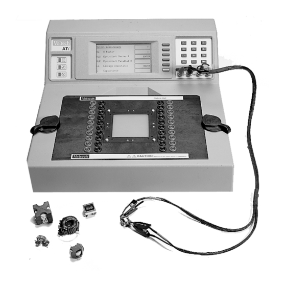
Page 230: Description
5.2 D ESCRIPTION The Voltech AT Series fixture system allows you freedom and flexibility when considering your fixturing needs. All fixtures are mounted on fixture boards, which are available as a blank fixture plate and also as fixture kit, which contains parts to help you. - Page 231 IXTURES C. 40-Socket Fixture A fixture board fitted with 40 4mm sockets. 20 red (power) and 20 black (sense). The sockets are wired to the 40 contacts, which align with the tester's 40 nodes. This complete fixture may be used for convenient wiring to existing fixtures or as a means of connecting flying leads and clips for use in developing test programs or testing small quantities.
-
Page 232: Basic Fixture Plate
IXTURES 5.2.1 B ASIC IXTURE LATE The Fixture Plate may be used to mount existing test fixtures onto an AT Series Tester, or to create test fixtures for flying lead parts where spring probes are not required. Fixture Plate Components 1. -
Page 233: Custom Fixture Kit
IXTURES 5.2.2 C USTOM IXTURE The Custom Fixture Kit enables many types of transformers and other wound components to be quickly and securely connected to an AT Series tester for fast and accurate testing. The system can accommodate transformer sizes of up to 63.5mm (2.5”) and, with suitable probes, parts with surface mounting, pin, blade or flying lead connections can be connected. - Page 234 3. Clamp An optional hand clamp holds the test piece against the test probes. The clamp is adjustable in height and in spring pressure. Voltech Part No. 91-187 Guides 12 adjustable guides are supplied to locate the test piece in the fixture quickly and accurately.
-
Page 235: Socket Fixture
A variety of clips and posts can be used to enable connection to the component under test. When testing larger quantities of the same component (50 or more) then a custom fixture solution is strongly recommended. Ask your Voltech supplier for details of the Custom Fixture Kit. 5-11... -
Page 236: Fixture System Specification
IXTURES 5.3 F IXTURE YSTEM PECIFICATION The Voltech custom fixture is designed to connect to wound components with the following characteristics: Size: A footprint of up to 63.5mm square A height of up to 63.5mm A connection matrix up to 60mm square... -
Page 237: Fixture Parts Available From Voltech
MORE INFORMATION: A comprehensive guide to the construction of your own custom fixtures is supplied with each custom fixture plate kit. A copy of the guide is also available on the ATi CD-ROM in Adobe PDF format. Please contact your Voltech supplier for more information or visit our website at www.voltech.com for details. - Page 238 IXTURES Example probe box drilled for multiple RM bobbin types M Series Kelvin Fixture 5-14 OLTECH ANUAL...
-
Page 239: Fixture Plate (Voltech Part Number 91-184)
IXTURES 5.4.1 F 91-184) IXTURE LATE OLTECH UMBER Designed for mounting existing fixtures to an AT series tester, the fixture plate comprises: Item 1 Base plate (including contact pins) with cover Item 2 Test piece interface plate Fittings and fasteners for above. 5-15 OLTECH ANUAL... -
Page 240: Socket Fixture (Voltech Part Number 91-186)
IXTURES 5.4.2 C 91-185) USTOM IXTURE OLTECH UMBER A kit of parts for constructing your own fixtures. Interconnecting wire, test probes or clips and a drilling template will also be required. The custom fixture kit comprises: Item 1 Base plate (including contact pins) with cover Item 2 Test piece interface plate Item 3... -
Page 241: Connection Lead Set (Voltech Part Number 78-030)
5.4.6 T OOLING Drilling templates are available in a variety of sizes (1.27mm, 2.00mm, 2.50mm, 2.54mm, 3.81mm) and are sold as a pack. Pack of 5 (1 of each pitch) drilling templates. Voltech Part No. 50-307 5-17 OLTECH ANUAL... -
Page 242: Kelvin Connections
‘Kelvin’ or 4–terminal connections are commonly used in precision measurement systems to obtain accurate measurements of impedance. Each of the ATi’s 20 measurement nodes (including the BNC connectors) consists of two terminals (Power and Sense) to allow complete 4-terminal testing. - Page 243 ‘Sense’ leads. The voltage measuring circuit is designed to have a very high input impedance (10MΩ on the ATi) and so negligible current flows in the Sense leads, there being a negligible error in the voltage measurement.
- Page 244 IXTURES V = 100mV 2mΩ 2mΩ 2mΩ 2mΩ 2mΩ 2mΩ 2mΩ ≅ 5mΩ 5mΩ 5mΩ 5mΩ 5mΩ 5mΩ 5mΩ R = 1.000Ω 4-wire measurement circuit The current flowing is the same: I = 100.0mV / 1014mΩ Ω Ω Ω = 98.62mA But the voltage measured is now: 1.000Ω...
- Page 245 IXTURES Ideally, all impedance measurements would be made using Kelvin connections. However, many terminals do not permit the use of four wires all the way to the body of the component under test. In such cases, separate power and sense leads are used up to the base of the terminal, and the length of ‘common’...
- Page 246 POWER terminals are all on the outside of the fixture area. SENSE terminals are all on the inside of the fixture area. The BNC to clip leads supplied with your ATi provide true 4-terminal Kelvin connections. IMPORTANT: Kelvin four terminal connections are generally advised to be used in all test fixtures;...
- Page 247 IXTURES When Kelvin connections are not possible because of space limitations, use a semi-Kelvin connection. Below are two examples of Kelvin connections: Clips supplied with BNC leads Kelvin pins 5-23 OLTECH ANUAL...
- Page 248 IXTURES 5-24 OLTECH ANUAL...
-
Page 249: Front -Panel Modes
RONT ANEL ODES OLTECH ANUAL... - Page 250 RONT PANEL ODES OLTECH ANUAL...
-
Page 251: Lcr Mode Basic Functions
RONT PANEL ODES Contents – Front-panel Modes 6.1. LCR M ..............6-5 ASIC UNCTIONS 6.1.1. LCR (BNC) Mode ..................6-7 6.1.2. LCR (FIX) Mode ..................6-11 6.1.3. Insulation Resistance ................6-13 6.2. T LCR M ...........6-17 ESTS VAILABLE IN THE ODES 6.3. - Page 252 RONT PANEL ODES OLTECH ANUAL...
-
Page 253: Lcr (Bnc) Mode
ASIC UNCTIONS As well as executing complete test sequences at high speed on multiple windings for production testing, the ATi can make LCR and turns ratio-type measurements on a component or single winding without using the PC-based test program editor. - Page 254 Two 'LCR' modes are available. LCR (BNC) mode uses the flexible leads attached to the four connectors on the control panel of the ATi to perform LCR (Inductance, Capacitance, Resistance)-type measurements on a single winding or component. LCR (FIX) mode uses nodes 13, 14, 15 and 16 of the fixture bay to perform LCR-type measurements plus Turns Ratio, Leakage Inductance and Interwinding Capacitance on two windings of a transformer.
- Page 255 RONT PANEL ODES 6.1.1 LCR (BNC) M Press the LCR (BNC) softkey, and the ATi immediately begins to make measurements. Ensure that DC Bias current is switched off before connecting and disconnecting component under test. The upper measurement is that of the parameter selected by the 1st (upper) softkey.
- Page 256 (see below). If the impedance of the part is very low, the ATi might not be able to supply sufficient current to maintain the programmed voltage. In this case, the voltage measured will be less than the program voltage.
- Page 257 RONT PANEL ODES Remove any fixture from the fixture bay and ensure these nodes (18 and 20) are clear before using the BNC terminals. The top softkey (number 1) allows you to move through the visible options. Press softkey 1, and you will see: Lp and Q The options for the second display line have changed as appropriate and can be changed by pressing the softkey 3.
- Page 258 Lp and D More tests are available by pressing 'More (1/3)', softkey 2: θ Z and Please see the sections following LCR (FIX) for details of how to use the front- panel LCR modes of the ATi. 6-10 OLTECH ANUAL...
-
Page 259: Lcr (Fix) Mode
The ATi is making measurements on nodes 13 and 15 (the 'primary') and nodes 14 and 16 (the 'secondary'). The LCR fixture supplied with your ATi has four Kelvin leads already connected to these nodes. 6-11... - Page 260 RONT PANEL ODES To change from measurements on the primary (nodes 13, 15) to measurements on the secondary (nodes 14, 16) press softkey 5, 'Pri Sec'. For measurements of TR (turns ratio) and TRL (turns ratio by inductance), softkey 5 toggles the display of measured test conditions. It does NOT alter the designation of primary (13,15) and secondary (14,16).
-
Page 261: Insulation Resistance
RONT PANEL ODES By default, the number of primary turns is assumed to be 1. In this example: Np : Ns 1 : 0.365 To display the actual number of turns as measured, enter the number of primary turns by pressing the appropriate buttons on the numeric keypad. (Note: Only numbers and a decimal place can be entered for Np.) E.g., Np = 1000 Np : Ns... - Page 262 RONT PANEL ODES OFF contols are provided for maximum operator safety. To measure insulation resistance, select IR from either the LCR (BNC) or LCR (FIX) modes. CAUTION: The insulation resistance test can generate voltages of up to 500V DC. Although the available energy of the source has been limited in accordance with EN61010-1, care should be taken to avoid accidental or unexpected electrical shocks.
- Page 263 RONT PANEL ODES Settings for the voltage integration can be changed by pressing softkey 4, ‘Settings’. A 'Print' option is included in this menu. Press softkey 1 ‘ IR Voltage’ And then press 'Enter V' to adjust the IR Voltage. 6-15 OLTECH ANUAL...
- Page 264 RONT PANEL ODES Enter the required test voltage using the 12-key numeric keypad. Press softkey 1, ‘ENTER’, to accept the value that you have typed. Press softkey 5, ‘CANCEL’, to discard changes and return to the previous menu. Press softkey 4, ‘DELETE’, to correct mistakes. Insulation resistance set-ups cannot be stored in memory, but the voltage and used nodes are automatically stored and recalled the next time that IR is selected.
- Page 265 RONT PANEL ODES 6.2 T LCR M ESTS VAILABLE IN THE ODES The available combinations are: More (1/4) Softkey 1 Softkey 3 Q, D, Rs Q, D, Rp D, Q, Rs D, Q, Rp More (2/4) Softkey 1 Softkey 3 θ, Q, D More (3/4) Softkey 1...
- Page 266 RONT PANEL ODES The symbols used are: Measurement Symbol Units Display Units Ω DC Resistance Ohms Ω DC Resistance Using High- Ohms voltage Source Ω AC Resistance – Series Circuit Ohms Ω AC Resistance – Parallel Circuit Ohms Inductance – Series Circuit Henries Inductance –...
- Page 267 RONT PANEL ODES 6.3 LCR M ENUS See the previous section for details of the tests that are available. The following flow diagrams describe the menu structure for LCR (BNC) and LCR (FIX) modes. 6.3.1 LCR (BNC) M LCR (BNC) Lp Cs Cp LCR (FIX) More (1/3)
- Page 268 RONT PANEL ODES 6.3.2 LCR (FIX) M LCR (BNC) LCR (FIX) Lp Cs Cp Execute More (1/4) Program D Rs More (2/4) θ θ θ θ Settings More (3/4) TRL LL C Self-Test Settings More (4/4) EXIT Settings PHAS EXIT Settings EXIT EXIT...
-
Page 269: Lcr Modes
6.3.3 LCR M ETTINGS For maximum convenience and ease of use, the ATi automatically chooses the voltage and frequency at which the LCR mode tests are carried out. The test conditions can also be programmed to fixed values to match the specification of a part or to ensure that a batch of parts are tested at exactly the same conditions. - Page 270 RONT PANEL ODES Press the 'Settings' softkey to reveal the settings menu. Press the 'Signal' softkey to show the signal settings. 6-22 OLTECH ANUAL...
- Page 271 RONT PANEL ODES Note that in LCR (BNC) mode there is only one set of conditions to choose and that the 'Pri Sec' softkey is thus not shown. On the bottom line of this display, the last measurement and its measurement conditions are displayed if they are available.
- Page 272 RONT PANEL ODES Press ‘Fix’ to enter the value currently being measured by the ATi. (This does not apply to ‘Ibias’, the DC bias current.) Press ‘Enter’ to accept the value that you have entered. Press ‘Auto’ to have the ATi automatically choose a voltage or frequency.
- Page 273 RONT PANEL ODES When the ‘Shift’ key (softkey 6) is pressed, it is shown in reverse video. Press ‘5’ with the ‘Shift’ key in reverse to enter the multiplier k (x1,000). Press ‘6’ with the ‘Shift’ key in reverse to enter the mulitiplier M (x1,000,000). Press softkey 4, ‘Delete’, to correct mistakes.
- Page 274 RONT PANEL ODES New settings are diplayed as above, once they have been stored. Since no measurements have been made with these new conditions, measured values cannot be displayed on bottom line. Having entered fixed values of voltage, frequency and Ibias as required, and pressed softkey 6 ‘OK’, the screen will show: The ‘Bias’...
- Page 275 The integration level controls details of the measurement method including the number of readings that are averaged together to provide the displayed measurements. To achieve the specified accuracy of the ATi, the default 'Medium' measurement should be chosen. Choosing 'Short' integration will provide faster but less stable and accurate results.
- Page 276 Print Press the 'Print' softkey in the settings menu, and the measurement information displayed will be output to the printer port of the ATi. Measurements can be recorded on any standard printer with a conventional PC-type parallel centronics input. The output is formatted using standard codes, so that a simple 40-column ticket printer may be used.
-
Page 277: Compensation
Measured V Winding under test The ATi is fully compensated at the factory for a broad range of frequencies, and compensation is often not required when using the LCR modes. If compensation is required, one of the following measurements will be... - Page 278 RONT PANEL ODES To compensate for the effect of stray inductance, the ATi must make a measurement with a short-circuit in place of the winding(s) under test. This is called short-circuit compensation. The short-circuit should be made of a piece of copper wire that is as short as possible.
-
Page 279: Performing Compensation
The 'One' short or open-frequency compensation options will be available if you have chosen any fixed frequency. Choosing 'One' sets up the ATi to perform compensation measurements at the chosen frequency only and is the preferred choice. Choosing 'All' will set up the tester to re-compensate at all frequencies, and this can take up to two minutes or more and is not normally necessary. - Page 280 Press softkey 6 ‘OK’ to use any compensation measurements that have just been made and return to the previous LCR screen. During short or open circuit compensation, the ATi is making very accurate measurements of the small stray or parasitic components. Remember that the power &...
-
Page 281: Compensation Fail
RONT PANEL ODES measurement may take up to 2 minutes, during which you will see the following display: Press softkey 5, ‘CANCEL’, at any time to cancel or stop the compensation measurement, and you will be returned to the previous screen. Once both short and open circuit compensation have been performed succesfully, the words ‘comp req' will be removed from the compensation screen and from the main LCR or Rdc IR measurement screen. - Page 282 Check the connection (either short or open circuit ) and repeat the compensation measurement. In the unlikely event that compensation continues to fail, you can use the ATi without compensation (‘comp req' will be shown on the display), while contacting your Voltech supplier for applications assistance.
-
Page 283: Lcr Mode Rror Messages
This means that the ATi will automatically compensate for lead resistance and (if 4-wire Kelvin connections are used) the contact resistance between connector and the part under test. -
Page 284: Program V
Other measurement circuit. Measured V Program V There are circumstances when the ATi cannot maintain the measured voltage to be equal to the program voltage. For example, if the AC impedance of the winding under test is only 0.1Ω at the specified frequency, and you have specified a 5V test signal, then the AT would have to supply 5V / 0.1Ω... - Page 285 You could, of course, choose AUTO values of voltage and current. In either case, the ATi will not sustain any damage, even if it is left permanently in the overload condition.
- Page 286 Examples are attempting to enter ‘AUTO’ frequency when a fixed voltage has already been entered or entering a value outside the specification of the ATi - such as 10MHz for test frequency.
- Page 287 ODES 6.6 P ROGRAM As well as using the AT Editor software to create test programs for the ATi, programs for your ATi tester may be created directly from the instrument’s front panel. From the top-level menu, choose softkey 1, ‘Programs’.
-
Page 288: Creating A New Test Program
RONT PANEL ODES 6.6.1 C REATING A ROGRAM In order to create a new test program, select ‘* New program *’, using the arrow softkey, and choose ‘Set-up’, softkey 2. The next screen shown is the test selection screen, initially, with the absence of any tests. - Page 289 Use the arrow key (softkey 2) to select a test to be set up. For example, scroll down one line, to ‘R – Winding Resistance’, and press ‘Enter’ to set up a winding resistance test on your ATi tester. The next screen that you will see is the set-up screen for the selected test. In this example, the ‘Set up R’...
- Page 290 RONT PANEL ODES Use the arrow key to scroll through and set up the test parameters. For example, to set up limits, scroll to the ‘Limit type’ line and press softkey 3 three times to enter both minimum and maximum limit values. Use the down arrow key, again, to scroll to the ‘Minimum limit’...
- Page 291 RONT PANEL ODES Then, scroll down, again, to choose your high and low nodes. Choose ‘Next’. At the following display (see below), you may choose to ‘Measure’, if the test that is being set up, supports this functionality. Pressing ‘Measure’ will update the limits as well as signal and frequency, if those parameters are set to ‘Auto’, similar to the ‘Measure’...
-
Page 292: Setting Up Test Program Options
RONT PANEL ODES Choosing ‘OK’ will return you to the program test selection screen, which should now correctly display the test parameters that have been entered in a table format (see below). Note: The ‘OK’ softkey does not allow you to exit the test set-up screen until all required test parameters have been entered. - Page 293 RONT PANEL ODES set the test program name, fixture ID and all other program options that are also available in the AT Editor software. For example, under ‘Name’, enter TUTORIAL as the program name and under ‘Fix ID’, enter UNIVERSAL as your fixture ID. To enter those names, scroll to the appropriate line, use the ‘Delete’...
- Page 294 RONT PANEL ODES Once you have completed the program options set-up, press ‘OK’ to return to the program test selection screen and ‘OK’ again to confirm your set-up. Note that, if a password has been set, the AT requests the password to be entered before the program can be saved.
-
Page 295: Running A Test Program
RONT PANEL ODES A “Password Valid” screen will confirm the correct password entry and return you to the program screen, which now lists the new test program that has been created. 6.6.3 R UNNING A ROGRAM To run the program, use the arrow keys to select it and choose the ‘Run’ softkey. -
Page 296: Password Protection
ASSWORD ROTECTION The ATi’s front-panel program mode allows the operator to edit test programs that are stored in the AT Server or the AT’s local program store, save new or modified programs or delete test programs directly from the front panel. To help protect existing test programs and their set-up, two AT passwords may be created—a Server password and a local password. - Page 297 As well as from within the Editor software (see chapter 3), the internal, local AT password may be set up directly from the main set-up menu of the ATi. From the top-level instrument menu, choose ‘Set-Up’. At the set-up screen, choose softkey 2, ‘Set-Up’.
- Page 298 RONT PANEL ODES If a password has already been set, the existing password must be entered at the screen below, before a new internal password can be set. The internal AT password protection may be removed by setting the password to a blank password, i.e., not enter any characters.
-
Page 299: Tests And Test Conditions
ESTS AND ONDITIONS OLTECH ANUAL... - Page 300 ESTS AND ONDITIONS Contents – Tests and Test Conditions 7.1. I ..................7-4 NTRODUCTION 7.1.1. Choosing Tests for a Transformer............... 7-4 7.1.2. CTY – Continuity ..................7-12 7.1.3. R – DC Resistance..................7-13 7.1.4. R2 – DC Resistance Match............... 7-16 7.1.5.
- Page 301 7.1.26. ANGL – Phase Angle of Impedance............7-105 7.1.27. PHAS – Interwinding Phase Angle ............7-108 7.1.28. TRIM – Pause Testing in Order to Trim a Component Value ....7-111 7.1.29. OUT – Control External Devices ............7-113 7.1.30. LSBX – Inductance with External Bias (Series Circuit)......7-116 7.1.31.
-
Page 302: Introduction
ONDITIONS 7.1 I NTRODUCTION Tests and Test Conditions This chapter provides guidance for the use of each of the tests currently available for the ATi. For the latest information please check the Voltech web site at: www.voltech.com 7.1.1 C HOOSING... -
Page 303: Cty - Continuity
A continuity check is a very quick test to determine if the transformer has been inserted correctly into the fixture. Used with the ‘Stop on Fail’ feature of the ATi, the transformer can be re-seated without wasting test time or recording a ‘FAIL’. - Page 304 A higher than expected leakage inductance can indicate inaccurately aligned core halves or poor layering of the windings. Check between the primary and the secondaries. (The ATi automatically creates short-circuits across the secondary windings that you specify for this test).
- Page 305 Additional tests can be purchased at any time, and are available on disk or by e-mail, so that your ATi can be upgraded in a few minutes with the aid of the Voltech Editor software running on a PC.
- Page 306 ESTS AND ONDITIONS circumstances, any measurement instrument may report negative inductance values and measurement errors. Should these symptoms be observed, reduce the test frequency to avoid problems. The frequency at which the inductive impedance equals the capacitive impedance (X ) is known as the self resonant frequency (SRF) of the component.
-
Page 307: Rdc Resistance
Tests Currently Available Test Description Transformer Application Reason for Test Checks properly installed Continuity fixture and part Checks properly installed fixture and part, correct wire DC Resistance used and integrity of terminations Checks matching between DC Resistance Match SMPS, audio & telecom windings Inductance Checks primary turns, right... -
Page 308: Resp Frequency Response
Bias current than is possible with ZB test. Check www.voltech.com for the latest list of available tests. Each test is described in detail in the following pages, together with programming guidance for use with the Voltech PC Editor. 7-10... - Page 309 * These tests require the use of one or more Voltech DC1000 Precision DC Bias Current Sources. Contact your Voltech sales office for details. 7-11 OLTECH ANUAL...
- Page 310 Used together with the ‘Stop on Fail’ option, CTY will allow you to re-insert a transformer into the fixture without recording a ‘FAIL’ or wasting further test time. CTY is a production-oriented test and is not available in the ATi’s front panel LCR meter mode. Programming the Test Using the PC Test Editor...
- Page 311 7.1.3 R – DC R ESISTANCE Measurement Range Basic Accuracy 0.1% 10µΩ to 10MΩ R1 represents the resistance of the copper wire used to wind the transformer. When current flows in the winding, the resistance causes losses in the winding R losses), which cause undesirable heating within the transformer.
- Page 312 ESTS AND ONDITIONS Choosing the Test Signal The DC test signal is set automatically according to the value specified as maximum in the test limits: Maximum <0.1Ω <1Ω <10Ω <100Ω <1kΩ <10kΩ >10kΩ Resistance Test 400mA 200mA 100mA 30mA 8.0V 300µA Signal Programming the Test Using the PC Test Editor...
- Page 313 If the "User Offset Enabled" check box is checked, a value can be entered into the edit box. The value entered (in the units shown) is then added to any results returned from the AT tester. This function can be used to adjust for measurement fixture effects that cannot be compensated for or to compensate the fixture manually so a compensation stage is not required to obtain the correct readings.
- Page 314 ESTS AND ONDITIONS 7.1.4 R2 – DC R ESISTANCE ATCH Measurement Test Test Basic Range Voltage Frequency Accuracy 1:1000 to 1000:1 0.2% AT Series Tester Where Used The DC resistance match test – as opposed to an ordinary DC resistance measurement (R) - is used on audio and telecommunications transformers, where it is important that the resistance of different pairs of windings is controlled and matched to a specified ratio.
- Page 315 Choosing Test Conditions For optimum accuracy and performance, use the test conditions shown in the DC resistance section of this chapter for each of the two windings. Programming the Test Using the PC Test Editor • Select the integration time required. •...
- Page 316 ESTS AND ONDITIONS • If the "User Offset Enabled" check box is checked, a value can be entered into the edit box. The value entered (in the units shown) is then added to any results returned from the AT tester. •...
- Page 317 Faults in numbers of turns, core material and core gapping may be determined using this test. For line frequency iron cored transformers where the inductance varies rapidly with voltage a magnetizing current test (MAGI) is recommended. (The MAGI test is only available on the Voltech AT3600). 7-19 OLTECH ANUAL...
- Page 318 ESTS AND ONDITIONS Test Conditions To measure inductance, the tester applies an AC voltage across the selected windings and measures the voltage across and the current through the winding. Using harmonic analysis, the measured voltage is divided by the current to obtain the complex impedance from which the inductance is extracted.
- Page 319 → 100H 50Hz → 100H 50Hz → 10kH 20Hz Ideal Test Conditions for Inductance Measurement The test conditions can also be determined automatically by the ATi according to this table: Specified voltage Specified current Auto Auto Signal Specified Specified Specified...
- Page 320 ESTS AND ONDITIONS Programming the Test Using the PC Test Editor Choose the integration period (normally ‘Medium’) and enter the terminals to be measured. Use the PC Editor’s ‘Measure’ button (together with a sample part) if you are unsure of how to choose the test conditions. 7-22 OLTECH ANUAL...
- Page 321 Notes When choosing test conditions, the following potential problems should be considered: a) Current Levels The upper voltage limits should be chosen to give a maximum current level of about 50mA rms for the lowest inductance expected. In some cases, this current may cause core saturation, and a lower voltage should be used.
- Page 322 This can be a problem when trying to compare measurements made on commercially available impedance bridges, or component testers, with measurements made using the ATi. The test signal in such bridges is usually determined within the instrument, and is often at a fixed frequency and at a voltage level that is not guaranteed to be constant for all value of inductance.
- Page 323 Test limits should be set as close as possible to detect assembly faults. A transformer made with a pair of gapped ferrite cores can often be tested to a tolerance of ±2%. For un-gapped cores, the tolerance may have to be as much as ±20% because of the core’s manufacturing tolerance.
- Page 324 ESTS AND ONDITIONS 7.1.6 QL – Q UALITY ACTOR Measurement Test Test Basic Range Voltage Frequency Accuracy 0.001 to 1000 1mV To 5V 20Hz To 3MHz 0.5% When a transformer is energized, the changing magnetic field in the core causes two types of losses: hysteresis losses and eddy current losses. The total of these losses can be represented on the equivalent circuit of a transformer by a resistance associated with the inductance of the winding.
- Page 325 Choosing the Test Signal For optimum accuracy and performance, use the test conditions chosen for inductance in the previous section of this chapter. The test conditions can also be determined automatically by the ATi according to this table: Specified voltage...
- Page 326 ESTS AND ONDITIONS Programming the Test Using the PC Test Editor Choose the integration period (normally ‘medium’) and enter the terminal to be measured. Use the Editor’s ‘Measure’ button (together with a sample part) if you are unsure of how to choose the test conditions. Choosing Test Limits The test limits can be: A nominal value together with + and –...
- Page 327 Typically, Q is tested against a minimum value. A typical ferrite cored transformer may have a Q >20. A specially designed low loss transformer may have a Q >100. Because Q is a ratio of two impedances it has no units. If the "User Offset Enabled"...
- Page 328 ESTS AND ONDITIONS δ δ δ δ 7.1.7 D – D ISSIPATION ACTOR OR Measurement Test Test Basic Range Voltage Frequency Accuracy 0.001 to 1000 1mV to 5V 20Hz to 3MHz 0.5% SEE ALSO THE CAPACITOR TESTING SECTION OF THIS CHAPTER. AT Series Tester The parameter ‘D’...
- Page 329 Choosing the Test Signal For optimum accuracy and performance, use the test conditions chosen for capacitance in a later section of this chapter. The test conditions can also be determined automatically by the ATi according to this table: Specified voltage...
- Page 330 ESTS AND ONDITIONS Programming the Test Using the PC Test Editor Choose the integration period (normally ‘Medium’) and enter the terminals to be measured. Use the Editor’s ‘Measure' button (together with a sample part) if you are unsure of the nominal value. Choosing Test Limits The test limits can be: A nominal value together with + and –...
- Page 331 Use the PC Editor’s ‘Measure’ button (together with a sample part) if you are unsure of the nominal value. Typically, D is tested against a maximum value. A typical film dielectric capacitor may have a D < 0.01. Because D is a ratio of two impedances it has no units.
- Page 332 ESTS AND ONDITIONS 7.1.8 RLS, RLP – AC R ESISTANCE ERIES AND ARALLEL IRCUIT Measurement Test Test Basic Range Voltage Frequency Accuracy 1mV to 5V 20Hz to 3MHz 0.05% 10µΩ t o 10MΩ AT Series Tester The equivalent AC resistance of a winding may be different to that measured at DC.
- Page 333 Choosing the Test Signal For optimum accuracy and performance, use the test conditions chosen for inductance in the previous section of this chapter. The test conditions can also be determined automatically by the ATi according to this table: Specified voltage...
- Page 334 ESTS AND ONDITIONS Programming the Test Using the PC Test Editor Choose the integration period (normally ‘Medium’) and enter the terminals to be measured. Use the PC Editor’s ‘Measure’ button (together with a sample part) if you are unsure of how to choose the test conditions. Choosing Test Limits The test limits can be: A nominal value together with + and –...
- Page 335 Remember to click on the units of limits (mOhm, Ohm etc.) when entering absolute values as limits. Test limits should be set as close as possible to detect assembly faults. If the "User Offset Enabled" check box is checked, a value can be entered into the edit box.
- Page 336 ESTS AND ONDITIONS 7.1.9 LSB, LPB – I NDUCTANCE WITH ERIES AND ARALLEL IRCUIT DC Bias Measure Test Test Basic Range Voltage Frequency Accuracy 1mA to 1A 1nH 1MH 1mV to 5V 20Hz to 3MHz 0.05% AT Series Tester Inductance is the electrical parameter that is commonly used to check that a high-frequency transformer has been constructed according to its design and that it will operate properly in use.
- Page 337 Choosing Test Conditions For optimum accuracy and performance, use the test conditions chosen for inductance without bias in the previous section of this chapter. The test conditions can also be determined automatically by the ATi according to this table: Specified voltage...
- Page 338 ESTS AND ONDITIONS Programming the Test Using the PC Test Editor Choose the integration period (normally ‘Medium’) and enter the terminals to be measured. Do use the PC Editor’s ‘Measure’ button (together with a sample part) if you are unsure of how to choose the test conditions. Choosing Test Limits The test limits can be: A nominal value together with + and –...
- Page 339 Use Editor’s ‘Measure’ button (together with a sample part) if you are unsure of the nominal value. Remember to click on the units of limits (nH, mH etc.) when entering absolute values as limits. Test limits should be set as close as possible to detect assembly faults. A transformer made with a pair of gapped ferrite cores can often be tested to a tolerance of ±2%.
- Page 340 ESTS AND ONDITIONS 7.1.10 L2 – I NDUCTANCE ATCH Measurement Test Test Basic Range Voltage Frequency Accuracy 1:10000 to 10000:1 1mV to 5V 20Hz to 3MHz 0.1% The inductance of a winding is determined by the number of turns and the construction and dimension of the core materials;...
- Page 341 The frequency will be common to both windings being tested for match. The test conditions can also be determined automatically by the ATi according to this table: Specified voltage...
- Page 342 ESTS AND ONDITIONS Programming the Test Using the PC Test Editor Choose the integration period (normally ‘Medium’) and enter the terminals to be measured. Terminals (X) High and Low: Winding 1 Terminals (Y) ‘High’ and ‘Low’: Winding 2 Use the PC Editor’s ‘Measure’ button (together with a sample part) if you are unsure of how to choose the test conditions.
- Page 343 7.1.11 LL, LLO – L EAKAGE NDUCTANCE AND EAKAGE NDUCTANCE WITH FFSET Measurement Test Current Test Basic Range Frequency Accuracy 1nH to 1kH 20Hz to 3MHz 0.1% 20µA to 100mA LLO Offset Range: –1H to +1H in 1nH steps Due to imperfections in the coupling between windings, a short-circuited transformer acts as if there is inductive impedance in series with the winding.
- Page 344 ESTS AND ONDITIONS Test Conditions Leakage inductance is tested by measuring the inductance of a primary winding when one or more secondary windings are shorted out. (See also the LS test). Typically, the impedance to be measured is very small, so a constant current AC test signal is used to provide stable, accurate results over a broad range of values.
- Page 345 10mH 1kHz → 10mH 100mH 100Hz → 100mH 100Hz → 50Hz 500µA The test conditions can also be determined automatically by the ATi according to this table: Specified voltage Specified current Auto Auto Signal Specified Specified Specified Auto Frequency Note that a ‘fixed’ signal cannot be used with an ‘Auto’ frequency.
- Page 346 ESTS AND ONDITIONS Programming the Test Using the PC Test Editor Choose the integration period (normally ‘Medium’) and enter the terminals to be measured. The ‘Primary Terminals’ are where the test signal will be applied; the ‘Secondary Terminals’ will be short-circuited together. Note that more than one secondary can be short-circuited at the same time by adding more of the available terminals to the ‘used’...
- Page 347 In order to protect transformer windings, the test current when measuring leakage inductance is limited in the table to 50mA maximum. In addition, the problem of self-resonant frequency listed under the primary inductance test also applies when measuring leakage inductance, so always use the lower of the available band of frequencies.
- Page 348 ESTS AND ONDITIONS 7.1.12 C – I NTERWINDING APACITANCE ARALLEL IRCUIT Measurement Test Test Basic Range Voltage Frequency Accuracy 100fF to 1mF 1mV to 5V 20Hz to 3MHz 0.1% SEE ALSO THE CS AND CP TESTS AND THE CAPACITOR TESTING SECTION OF THIS CHAPTER.
- Page 349 → 10nF 100nF 100Hz → 100nF 10µF 100Hz 500mV Test Conditions for Capacitance Measurement The test conditions can also be determined automatically by the ATi according to this table: Specified Auto Auto Voltage Specified Specified Auto Frequency Note that a ‘fixed’ voltage signal cannot be used with an ‘Auto’ frequency.
- Page 350 ESTS AND ONDITIONS Programming the Test Using the PC Test Editor Choose the integration period (normally ‘Medium’) and enter the terminals to be measured. More than one terminal can be ‘High’ and more than one terminal can be ‘Low’. This is to allow testing of the complete primary to secondary capacitance of a transformer by taking all primary terminals ‘High’...
- Page 351 When choosing the test conditions, the following potential problems should be considered: a) Current Levels For larger capacitance, particularly at higher frequencies, the current flowing during the measurement can be very high, and similarly the measured current could also be very small for small capacitance at lower frequencies and voltages.
- Page 352 ESTS AND ONDITIONS > A minimum value only < A maximum value only Use the PC Editor’s ‘Measure’ button (together with a sample part) if you are unsure of the nominal value. Remember to click on the units of limits (pF, nF etc.) when entering absolute values as limits.
- Page 353 7.1.13 CS CP – C APACITANCE ERIES AND ARALLEL IRCUIT Measurement Test Test Basic Range Voltage Frequency Accuracy 100fF to 1mF 1mV to 5V 20Hz to 3MHz 0.1% SEE ALSO THE C TEST AND THE CAPACITOR TESTING SECTION OF AT Series Tester THIS CHAPTER.
- Page 354 Frequency Note that a ‘fixed’ voltage signal cannot be used with an ‘Auto’ frequency. CS and CP are currently only available on the Ati’s front panel LCR mode. Contact your local supplier or check the Voltech website at www.voltech.com for up to date information.
- Page 355 7.1.14 C2 – C APACITANCE ATCH Measurement Test Test Basic Range Voltage Frequency Accuracy 1:1000 to 1000:1 1mV to 5V 20Hz to 3MHz 0.2% Capacitance occurs in transformers due to the physical proximity of, and electrostatic coupling between, different turns of wire. In general, the capacitance is distributed between different layers within a winding, and between the outside layer of one winding and the inside layer of the next.
- Page 356 ESTS AND ONDITIONS Test Conditions To measure capacitance match, the tester makes two capacitance measurements (see the C test) and compares the two results. Limits for the match of the two measured capacitances may be set in terms of the ratio between them (e.g.
- Page 357 Choosing Test Conditions For optimum accuracy and performance choose test conditions based on the nominal value of capacitance as listed in the previous capacitance section. The test conditions can also be determined automatically by the ATi according to this table: Specified...
- Page 358 ESTS AND ONDITIONS 7.1.15 TR – T URNS ATIO AND HASING Measurement Test Test Basic Range Voltage Frequency Accuracy 1:100,000 100,000:1 1mV to 5V 20Hz to 3MHz 0.1% Applying an AC voltage to the primary of the transformer will produce an AC voltage in the secondary.
- Page 359 Test Conditions To measure turns ratio, the test signal is applied to one winding called the energized winding. The voltages across two other windings (one of which may be the energized winding) are measured. The turns ratio is then measured by dividing one measured voltage by the other, and making a compensation for the effects of winding resistance.
- Page 360 ESTS AND ONDITIONS The test conditions can also be determined automatically by the ATi according to this table: Specified Auto Auto Voltage Specified Specified Auto Frequency Note that a ‘fixed’ voltage signal cannot be used with an ‘Auto’ frequency. Programming the Test Using the PC Test Editor Choose the integration period (normally ‘Medium’).
- Page 361 Primary Terminals ‘High’ and ‘Low’: The zero phase reference terminals, which are often the same as the energized terminals. Secondary Terminals ‘High’ and ‘Low’: The turns ratio and polarity measurement will be made between the primary and secondary terminals. Use the PC Editor’s ‘Measure’ button (together with a sample part) if you are unsure of how to choose the test conditions.
- Page 362 ESTS AND ONDITIONS In this way windings that should be matched are treated equally during the test. 7-64 OLTECH ANUAL...
- Page 363 Choosing Test Limits The limits may be entered as: A nominal value together with a percentage tolerance (%) Enter the nominal Primary to Secondary ratio, together with the limits as positive and negative percentage values. An absolute number of turns (#) When limits are set as +/- an absolute number of turns, the tester converts these limits to the % type in the following way: = +/-...
- Page 364 ESTS AND ONDITIONS Which equates to the actual ratios with a one-turn error on the secondary. In general, the voltages obtained during any voltage turns ratio test will not equate exactly to the theoretical calculation of Np / Ns, because, for example, of the relative positions of the windings with respect to each other and the core.
- Page 365 How do I set limits that will detect a one-turn error on either the primary or the secondary? To do this you must set limits that will detect the smallest possible error. This will be due to the one-turn error being on the winding with the largest number of turns.
- Page 366 ESTS AND ONDITIONS 7.1.16 TRL – T URNS ATIO BY NDUCTANCE Measurement Test Test Basic Range Voltage Frequency Accuracy 1:100 100:1 1mV to 5V 20Hz to 3MHz 0.1% The correct ratio of the number of turns on one winding to the number of turns on another winding is important for the proper operation of any transformer.
- Page 367 Where Used The turns ratio by inductance test is used on transformers that have poor coupling btween windings and where a turns ratio by voltage (TR) test may not produce the expected result. For example, transformers for electronic lighting ballasts are often deliberately wound to have relatively large values of leakage inductance.
- Page 368 ESTS AND ONDITIONS Programming the Test Using the PC Test Editor Using the Measure Button to Set Test Parameters Select the integration period you require, enter the primary and secondary terminals, then click on the ‘Measure’ button as explained in the Editor section of this manual.
- Page 369 Setting the Primary and Secondary Parameters Manually To do this you will need to know the inductance of the primary and secondary windings. The optimum test conditions are chosen for an inductance value that is between the primary and secondary (L ×...
- Page 370 50Hz → 100H 50Hz → 100H 50Hz → 10KH 20Hz The ATi can automatically determine the test conditions according to the following table: Specified Auto Auto Voltage Specified Specified Auto Frequency Note that a ‘fixed’ voltage signal cannot be used with an ‘Auto’ frequency.
- Page 371 7.1.17 LVOC – L OLTAGE IRCUIT Measurement Test Test Basic Range Voltage Frequency Accuracy 1mV to 5V 20Hz to 3MHz 0.1% 100µV to 5V Applying an AC voltage to the primary of the transformer will produce an AC voltage in the secondary. Low Voltage Open Circuit measures the ‘open circuit’...
- Page 372 ESTS AND ONDITIONS frequency transformers at their operating point (up to 270V, 1kHz and 2A). See also the test TR – turns ratio. Test Conditions To measure low voltage open circuit, the test signal is applied to one winding called the energized winding. The voltages across another winding (or the same, energized winding) are measured.
- Page 373 The test conditions can also be determined automatically by the ATi according to this table: Specified Auto Auto Voltage Specified Specified Auto Frequency Note that a ‘fixed’ voltage signal cannot be used with an ‘Auto’ frequency. Programming the Test Using the PC Test Editor Choose the integration period (normally ‘Medium’).
- Page 374 ESTS AND ONDITIONS Primary Terminals ‘High’ and ‘Low’: The zero phase reference terminals that are often the same as the energized terminals. Secondary Terminals ‘High’ and ‘Low’: The turns ratio and polarity measurement will be made between the primary and secondary terminals. Use the PC Editor’s ‘Measure’...
- Page 375 7.1.18 IR – I NSULATION ESISTANCE Test Measurement Test Test Basic Range Voltage Frequency Accuracy 100V to 500V 1.0% 1MΩ to 1GΩ Transformer windings are often insulated from each other and from the core by insulating tape, enamel on the wire or by plastic moulding on the bobbin.
- Page 376 ESTS AND ONDITIONS To measure insulation resistance, the tester applies a DC voltage between two groups of windings with the windings in each group being shorted together. Each group may contain as many windings as you wish. The voltage and current are measured; dividing the voltage by the current gives the insulation resistance.
- Page 377 A value of 100MΩ is generally suitable for most applications. Where higher voltage safety testing is required, see the Hi-Pot tests that are available with the Voltech AT3600. If the "User Offset Enabled" check box is checked, a value can be entered into the edit box.
- Page 378 ESTS AND ONDITIONS 7.1.19 GBAL – G ENERAL ONGITUDINAL ALANCE Measurement Test Test Basic Range Voltage Frequency Accuracy 0 dB to 100 dB 1mV to 5V 20Hz to 3MHz 0.5dB Longitudinal balance is a measure of the common mode rejection ratio (CMRR) of a transformer.
- Page 379 audio and telecommunications transformers to the standards IEEE455 and FCC 68.310 and wherever similar connection methods are specified. Test Conditions The source and load resistors (RS and RL) and the measuring transformer are connected to the transformer under test as shown. This may be done automatically using the tester’s OUT test.
- Page 380 ESTS AND ONDITIONS FCC 68.310 Method (Used in USA) OUT1 OUT2 Fixture Transformer Energized (Vin) Measured (Vout) Terminals (X) Terminals (Y) Choosing Test Conditions The source and load resistors and the fixture transformer for the IEEE and FCC methods are assumed to be on the fixture, but are not shown on the Editor schematic.
- Page 381 Programming the Test Using the PC Test Editor The voltage and frequency are usually determined by the final application of the part under test. Select the integration period, which is normally ‘Medium’ Enter the required terminal names: Terminals (X) - the energized winding. Terminals (X) –...
- Page 382 ESTS AND ONDITIONS Choosing Test Limits The test limits can be: A nominal value together with + and – percentage limits. >< Minimum and maximum values > A minimum value only < A maximum value only Use the PC Editor’s ‘Measure’ button (together with a sample part) if you are unsure of the nominal value.
- Page 383 7.1.20 LBAL – L ONGITUDINAL ALANCE Measurement Test Test Basic Range Voltage Frequency Accuracy 0 dB to 100 dB 1mV to 5V 20Hz to 3MHz 0.5dB Longitudinal balance is a measure of the common mode rejection ratio (CMRR) of a transformer. That is, the ability of the transformer to reject unwanted noise signals that are common to both input terminals with respect to a common point.
- Page 384 ESTS AND ONDITIONS Test Conditions The source and load resistors (RS and RL) are connected to the transformer - this may be done automatically using the tester’s OUT test. Then, two measurements are performed using the circuits above, which the tester automatically configures.
- Page 385 Choosing Test Conditions The source and load resistors are not shown on the Editor schematic. They are switched in circuit using an OUT test that must be inserted in the program before the GBAL test. (The relay patterns associated with inserting and removing fixture resistors have deliberately not been included in the GBAL test dialogue for two reasons: a) it would make the dialogue too complicated, and b) it is not always necessary - e.g.
- Page 386 ESTS AND ONDITIONS Terminals (X) – the measured voltage VOUT1 Terminals (Y) – the energized terminals for creating a common mode voltage. Terminals (Y) – the measured voltage VOUT2 Note that the PC Editor’s ‘Measure’ button CANNOT be used to determine the test voltage.
- Page 387 7.1.21 RESP – F REQUENCY ESPONSE Measurement Test Test Basic Range Voltage Frequency Accuracy -100dB to +100dB 1mV to 5V 20Hz to 3MHz 1.0dB Where Used The frequency response test, RESP, may be used to check that the variation in power loss of a telecommunications or audio transformer over a specified frequency range is less than specified limits.
- Page 388 ESTS AND ONDITIONS -5dB -10dB Frequency The result of a RESP test is a single value, chosen as follows: If all the referred ILOS results are at or inside the specified limits, the result of a RESP test is the referred ILOS result that is closest to the limit. If any of the referred ILOS results are outside the specified limits, the RESP result is the referred ILOS result that is furthest away from the limit.
- Page 389 Programming the Test Using the PC Test Editor • Enter the voltage and frequency parameters of the reference test signal. • Select the integration time required. (Normally 'Medium') • Enter the names of the Hi and Lo input terminals. • Enter the names of the Hi and Lo output terminals.
- Page 390 ESTS AND ONDITIONS • Select OK. The test specification will then be displayed in the program window. Note that although resistors should be fitted to the fixture, there is no need to enter their values here since the RESP test result is the difference between two ratios based on the same resistor values.
- Page 391 7.1.22 ILOS – I NSERTION Measurement Test Test Basic Range Voltage Frequency Accuracy -100dB to +100dB 1mV to 5V 20Hz to 3MHz 0.5dB The insertion loss is a measure of the power lost by a transformer relative to the maximum theoretical power that the transformer could transmit to a given load.
- Page 392 ESTS AND ONDITIONS The tester applies the specified voltage Vin, and the voltage Vout is measured. The ratio of actual to theoretical power loss is calculated using the formula: ILOS = 10log ((Vin2 RL) / (4 Vout2 RS)) Choosing Test Conditions The voltage and frequency are usually determined by the final application of the part under test.
- Page 393 Choosing Test Limits The test limits can be: % A nominal value together with + and – percentage limits. >< Minimum and maximum values > A minimum value only < A maximum value only Use the PC Editor’s ‘Measure’ button (together with a sample part) if you are unsure of the nominal value.
- Page 394 ESTS AND ONDITIONS 7.1.23 RLOS – R ETURN Test Test Basic Measurement Voltage Frequency Accuracy Range -100dB to +100dB 1mV to 5V 20Hz to 3MHz 0.2% AT Series Impedance Z Tester The return loss is a measure of the impedance mismatch between the transformer and a transmission line.
- Page 395 The return loss is calculated using the formula: ( Z / Z ) RLOS = 20 log – Z Where Z is a complex impedance in the form Z= R + jX ½...
- Page 396 ESTS AND ONDITIONS Programming the Test Using the PC Test Editor Choose the integration period (normally ‘Medium’) and enter the ‘High’ and ‘Low’ Terminal names. The reference impedance values are the nominal values of the transmission line to which the transformer will be connected in its final application. This is a complex impedance Z = R + jX where R is the real part of the impedance and X is the imaginary part.
- Page 397 Xc = 1/ 2π π π π fC. Note that the PC Editor’s ‘Measure’ button CANNOT be used to determine the test voltage. Choosing Test Limits The test limits can be: A nominal value together with + and – percentage limits. ><...
- Page 398 ESTS AND ONDITIONS 7.1.24 Z, ZB – I MPEDANCE MPEDANCE WITH Measurement Test Test Basic Range Voltage Frequency Accuracy 1mV to 5V 20Hz to 3MHz 0.2% 1mΩ to 1MΩ The impedance of a transformer is usually complex, that is it consists of real (resistive) and inductive or capacitive (imaginary) parts.
- Page 399 To measure Z, the tester applies the specified voltage and (for impedance with bias, the specified DC bias current). By measuring both the applied AC voltage and the resulting AC current, the total impedance is calculated. Z is the magnitude of the complex impedance Z = √ (R Choosing Test Conditions The voltage and frequency are usually determined by the final application of the part under test.
- Page 400 ESTS AND ONDITIONS Choose the integration period (normally ‘Medium’) and enter the ‘High’ and ‘Low’ Terminal names. For the impedance with bias test, you may also select a DC bias current. Note that the Editor’s ‘Measure’ button CANNOT be used to determine the test voltage.
- Page 401 7.1.25 X – R EACTANCE Measurement Test Test Basic Range Voltage Frequency Accuracy 1mV to 5V 20Hz to 3MHz 0.2% 1mΩ to 1MΩ The impedance of a transformer is usually complex, that is it consists of real (resistive) and inductive or capacitive (imaginary) parts. The total impedance at a specified frequency is the vector sum of these parts.
- Page 402 X is the imaginary part of the complex impedance Z = R + jX. Choosing Test Conditions The voltage and frequency are usually determined by the final application of the part under test. The X test is only available on the ATi’s front panel LCR mode. 7-104 OLTECH ANUAL...
- Page 403 7.1.26 ANGL – P HASE NGLE OF MPEDANCE Measurement Test Test Basic Range Voltage Frequency Accuracy 1mV to 5V 20Hz to 3MHz -360° to +360° 0.05° The impedance of a winding is usually complex as it consists of real (resistive) and inductive or capacitive (imaginary) parts. The phase angle φ...
- Page 404 ESTS AND ONDITIONS Measuring the phase angle of the impedance will help to determine that the part has been properly assembled using the correct cores and the right gauge of wire. Measurement Conditions The AT Series Tester applies the specified AC voltage to the winding under test.
- Page 405 Programming the Test Using the PC Test Editor Choose the integration period (normally ‘Medium’) and enter the ‘High’ and ‘Low’ Terminal names. Note that the PC Editor’s ‘Measure’ button CANNOT be used to determine the test voltage. Choosing Test Limits The test limits can be: A nominal value together with + and –limits of up to +90 and –90 deg.
- Page 406 ESTS AND ONDITIONS 7.1.27 PHAS – I NTERWINDING HASE NGLE Measurement Test Test Basic Range Voltage Frequency Accuracy 1mV to 5V 20Hz to 3MHz -360° to +360° 0.05° When the AC voltage across one winding is compared to the voltage across another, they may be different in amplitude and phase.
- Page 407 incorporated into the TR (Turns Ratio) test that can only determine +ve or -ve polarity. Test Conditions The AT Series Tester applies the specified AC voltage to one winding and measures the voltage produced across two windings, one of which may be the energized winding.
- Page 408 ESTS AND ONDITIONS Choose the integration period (normally ‘Medium’): Energized Terminals: The terminals where the test signal will be applied. This is normally the winding with the greatest number of turns. Primary Terminals ‘High’ and ‘Low’: The zero phase reference terminals that are often the same as the energized terminals.
- Page 409 7.1.28 TRIM – P AUSE ESTING IN RDER TO RIM A OMPONENT ALUE The TRIM test is used on signal, audio and telecommunications transformers and other components where a means of physically adjusting a parameter is provided. For example, the Q factor of a coil may be tuned to within specified limits by adjusting a trimmable core.
- Page 410 ESTS AND ONDITIONS Tests that may be TRIMmed include: R, RLS, RLP, LS, LP, LSP, LSB, Q, C, TR, LL, LLO, TR, L2, C2, GBAL, LBAL, ILOS, RLOS and Z. Choosing Test Conditions On selecting ‘TRIM - Trimming Adjustment’ from the Available Tests Window, the following dialogue box will be displayed: To program the test: Select OK.
- Page 411 The user relays may in turn be used to switch in external components such as impedance matching resistors (important for audio and telecommunications transformers) or to connect windings in series for subsequent testing. The user port is situated at the rear of the ATi. 7-113 OLTECH...
- Page 412 ESTS AND ONDITIONS See also the tests for audio and telecommunications transformers, LBAL, GBAL, ILOS, RLOS and Z. Most types of power and many signal transformers will be tested using the tester’s internal relay matrix to perform switching, and an OUT test is not required for these.
- Page 413 Note: The relay drivers are only set as and when the tester encounters an OUT test. The settings given will remain in place until another OUT test is encountered. Therefore if the settings are required for one part of the test program only, two OUT tests will be required, the first to turn the appropriate relay drivers on and the second to turn them back off.
- Page 414 20Hz to 3MHz 0.2% @ Q>10 250A This test requires the use of one or more Voltech DC1000 Precision DC Bias Current Sources. Contact your Voltech sales office for details. The inductance of a transformer winding while an external bias current is flowing through it may be tested using series or parallel equivalent circuit models.
- Page 415 To program the test: Enter the signal, frequency and bias current required for the test. Note that the signal is normally entered as a voltage by selecting the ‘mV’ or ‘V’ button; but you may optionally enter it as a current by selecting the ‘mA’ button.
- Page 416 20Hz to 3MHz 0.2% @ Q>10 250A This test requires the use of one or more Voltech DC1000 Precision DC Bias Current Sources. Contact your Voltech sales office for details. The inductance of a transformer winding while an external bias current is flowing through it may be tested using series or parallel equivalent circuit models.
- Page 417 To program the test: Enter the signal, frequency and bias current required for the test. Note that the signal is normally entered as a voltage by selecting the ‘mV’ or ‘V’ button; but you may optionally enter it as a current by selecting the ‘mA’...
- Page 418 0.2% 1mΩ to 1MΩ 3MHz This test requires the use of one or more Voltech DC1000 Precision DC Bias Current Sources. Contact your Voltech sales office for details. The Winding Impedance with External Bias test measures the impedance of a selected winding while applying a DC current from the DC1000 through the winding.
- Page 419 To program the test: Enter the value of a voltage (or current) for the signal and the required frequency of the test. Also enter the bias current you would like to apply. Please note that the Measure button may be used here. For information, refer to the ‘Test Program Editor’...
- Page 420 ESTS AND ONDITIONS >< Enter minimum and maximum values. > Enter just a minimum value. < Enter just a maximum value. Select OK. The test specification will then be displayed in the program window. 7-122 OLTECH ANUAL...
-
Page 421: Series And Parallel Circuits
ERIES AND ARALLEL IRCUITS The ATi can make measurements of many parameters such as Inductance (L), Capacitance (C) and AC resistance (R) using both the parallel and equivalent circuits. The measurements for the series or parallel equivalent circuits will not necessarily be the same and care should be taken when choosing which equivalent circuit to use when testing. - Page 422 ESTS AND ONDITIONS For an INDUCTIVE IMPEDANCE, Rs represents the copper losses in the wire and Rp represents the in-phase core losses. X (ωL) is usually much lower than Rp, so Rp is insignificant. Choose the SERIES equivalent circuit. If the inductance is large (> 1 Henry) and / or the series resistance (Rs) is very small, the parallel equivalent circuit is sometimes used.
-
Page 423: Capacitor Measurements
7.3 C APACITOR EASUREMENTS The ATi and its front panel LCR mode are ideal for making precise measurements on capacitors. Capacitance (Farads) To measure the capacitance, use the C test in the PC editor or simply select C on the top line of the LCR mode. The measurement conditions can be fully automatic or user programmed following the guidelines given earlier in this chapter. - Page 424 ESTS AND ONDITIONS ESR Equivalent Series Resistance This is also a measure of the losses in the capacitor. The ESR is the equivalent AC resistance of the series equivalent circuit. To measure ESR, choose the test RLS in the PC editor or select Rs SERIES circuit from the front panel LCR mode.
-
Page 425: Specifications
PECIFICATIONS OLTECH ANUAL... - Page 426 PECIFICATIONS OLTECH ANUAL...
-
Page 427: Specifications Summary - Available Tests
PECIFICATIONS Contents - Specifications 8.1. S – A ........8-5 PECIFICATIONS UMMARY VAILABLE ESTS 8.2. A – A ........8-8 CCURACY PECIFICATIONS VAILABLE ESTS 8.2.1. R Test......................8-8 8.2.2. LS, LP, LSB, LPB, RLS, RLP and X Tests ..........8-9 8.2.3. LL and LLO Tests..................8-10 8.2.4. - Page 428 PECIFICATIONS 8.4. EMC C ................8-35 OMPLIANCE 8.4.1. Declaration of Conformity................8-35 8.4.2. EMC Precautions ..................8-36 OLTECH ANUAL...
- Page 429 PECIFICATIONS 8.1 S – A PECIFICATIONS UMMARY VAILABLE ESTS User-Entered Test Data Test Measurement Range Test Signal Test Frequency Continuity 10kΩ - 10MΩ 10µΩ - 10MΩ 0.1% Resistance Resistance 1:1000 - 1000:1 0.2% Match Inductance (Series) 1nH - 1MH 1mV - 5V 20Hz - 3MHz 0.05% + Bias...
- Page 430 PECIFICATIONS User-Entered Test Data Test Measurement Range Test Signal Test Frequency Turns Ratio by 30:1 - 1:30 1mV - 5V 20Hz - 3MHz 0.1% Inductance Low Voltage LVOC 100µV - 5V 1mV - 5V 20Hz - 3MHz 0.1% Open Circuit Insulation 1MΩ...
- Page 431 PECIFICATIONS 1mV to 5V or Impedance with 20µA to 1mΩ to 1MΩ 20Hz to 3MHz 0.2% External Bias 100mA Notes 1. A = basic relative accuracy; full specifications follow. Specification at 23ºC ± 5ºC after one-hour warm-up and long integration. 2.
-
Page 432: Tests
PECIFICATIONS 8.2 A – A CCURACY PECIFICATIONS VAILABLE ESTS 8.2.1 R T The accuracy is based on the test conditions chosen to measure the winding resistance, and is given as: +A +A +A Where is the total accuracy (%) is the basic relative accuracy (%) is the calibration accuracy (%) is the correction for voltage level (%) is the correction for current level (%) - Page 433 PECIFICATIONS 8.2.2 LS, LP, LSB, LPB, RLS, RLP ESTS The accuracy is based on the test conditions chosen to measure the impedance of the parameter under test, and is given as: Where is the total accuracy (%) is the basic relative accuracy (%) is the calibration accuracy (%) is the correction for voltage level (%) is the correction for current level (%)
- Page 434 PECIFICATIONS 8.2.3 LL LLO T ESTS The accuracy is based on the test conditions chosen to measure the impedance of the parameter under test, and is given as: Where is the total accuracy (%) is the basic relative accuracy (%) is the calibration accuracy (%) is the correction for voltage level (%) is the correction for current level (%)
- Page 435 PECIFICATIONS 8.2.4 C, CS CP T ESTS The accuracy is based on the test conditions chosen to measure the impedance of the parameter under test, and is given as: Where is the total accuracy (%) is the basic relative accuracy (%) is the calibration accuracy (%) is the correction for voltage level (%) is the correction for current level (%)
-
Page 436: Ql Andd Tests
PECIFICATIONS 8.2.5 QL ESTS The accuracy of measuring Q factor and D factor is given as: Where is the basic total accuracy (%) is the basic relative accuracy (%) is the correction for current level (%) is the correction for Q or D factor (%) The value of A is given in the table in section 8.1 of this chapter. -
Page 437: Tr Test
PECIFICATIONS 8.2.6 TR T The accuracy is based on the test conditions chosen to measure the turns ratio, and is given as: +A +A +A +A Where is the total accuracy (%) is the basic relative accuracy (%) is the calibration accuracy (%) is the correction for primary voltage level (%) is the correction for secondary voltage level (%) is the correction for the turns ratio value (%) -
Page 438: Lvoc Test
PECIFICATIONS 8.2.7 LVOC T The accuracy for measuring open circuit voltage is given as: Where is the total accuracy (%) is the basic relative accuracy (%) is the calibration accuracy (%) is the correction for voltage level (%) The value of A is given in the section 8.1 of this chapter. -
Page 439: Trl Test
PECIFICATIONS 8.2.8 TRL T The accuracy for the test is given as: Where is the total accuracy (%). is the accuracy of the primary winding measurement (%). is the accuracy of the secondary winding measurement (%). To determine the values of A and A use the accuracy specification for series inductance. -
Page 440: Ir Test
PECIFICATIONS 8.2.9 IR T The accuracy is based on the test conditions chosen to measure the insulation resistance, and is given as: +A +A +A Where is the total accuracy (%) is the basic relative accuracy (%) is the calibration accuracy (%) is the correction for current level (%) is the correction for impedance level (%) The value of A... -
Page 441: L2, C2 And R2 Tests
PECIFICATIONS 8.2.10 L2, C2 R2 T ESTS The accuracy is dependent on the accuracy of the two inductance, capacitance or resistance measurements made, and is given as: Where is the total accuracy (%) is the accuracy of the X measurement (%) is the accuracy of the Y measurement (%) Refer to the accuracy specifications for the LS, C and R tests to determine the accuracy of the X and Y measurements. -
Page 442: Gbal Test
PECIFICATIONS 8.2.11 GBAL T The accuracy is based on the test conditions chosen to measure the longitudinal balance of the transformer under test, and is given as: +0.87(A +A +A ) Where is the total accuracy (dB) is the basic relative accuracy (dB) is the correction for calibration is the correction for the X measurement voltage level is the correction for the Y measurement voltage level... - Page 443 PECIFICATIONS 8.2.12 LBAL, ILOS RESP T ESTS The accuracy is given as: +0.87 A +A +A Where is the total accuracy (dB) is the basic relative accuracy (dB) is the correction for calibration is the correction for the input voltage level is the correction for the output voltage level The value of A is given in the table in section 8.1 of this chapter.
-
Page 444: Rlos Test
PECIFICATIONS 8.2.13 RLOS T The accuracy is given as: 0.174 x Where is the total accuracy (dB) is the total accuracy for the Z test (%) is V real imag Where is the measured voltage (V) is the measured current (A) is the real part of the reference impedance (Ω) real is the imaginary part of the reference impedance (Ω) -
Page 445: Zand Zb Test
PECIFICATIONS 8.2.14 Z ZB T The accuracy is given as: +A +A +A Where is the total accuracy (%) is the basic relative accuracy (%) is the calibration accuracy (%) is the correction for voltage level (%) is the correction for current level (%) The value of A is given in the table in section 8.1 of this chapter. -
Page 446: Angl Test
PECIFICATIONS 8.2.15 ANGL T The accuracy is given as: +A +A +A Where is the total accuracy (°) is the basic relative accuracy (°) is the calibration accuracy (°) is the correction for voltage level (°) is the correction for current level (°) The value of A is given in the table in section 8.1 of this chapter. -
Page 447: Phas Test
PECIFICATIONS 8.2.16 PHAS T The accuracy is given as: +A +A +A Where is the total accuracy (°) is the basic relative accuracy (°) is the calibration accuracy (°) is the correction for voltage level (°) is the correction for turns ratio (°) The value of A is given in the table in section 8.1 of this chapter. - Page 448 PECIFICATIONS 8.2.17 LSBX LPBX T ESTS The accuracy is based on the test conditions chosen to measure the impedance of the parameter under test, and is given as: Where is the total accuracy (%) is the basic relative accuracy (%) is the calibration accuracy (%) is the correction for voltage level (%) is the correction for current level (%)
-
Page 449: Interface Details
8.3 I NTERFACE ETAILS The following interfaces are available at the rear of the ATi: From left to right: Barcode – Server – Printer – Auxiliary (Editor) – Remote – User – Ground All these ports may be susceptible to damage from static discharge. - Page 450 PECIFICATIONS Signal name Signal name No connection No connection No connection No connection No connection The recommended barcode reader for the AT Series Testers is the ‘Smart Wand’ Barcode Reader from Hewlett Packard, (available from Farnell Electronic Components.) Hewlett-Packard List No: HBSW-8300 The HP ‘Smart Wand’...
-
Page 451: Server Port
PECIFICATIONS 8.3.2 S ERVER RS232 interface for connection to a PC Server running the Voltech AT Series Server software. 25-pin male D-type connector. Signal name Signal name Ground (Earth) No connection No connection No connection 8.3.3 A UXILIARY RS232 interface for connection to a PC running the Voltech AT Series Editor software. -
Page 452: Printer Port
PECIFICATIONS 8.3.4 P RINTER Standard parallel printer interface. 25-pin female D-type connector. Signal name Signal name !STROBE BUSY No connection !AUTOFD !ERROR !INIT !SLCTIN !ACKNLG Signals with a name starting with ! are active Lo. Printing options can be chosen from the ‘Options’ dialogue of the Editor software. - Page 453 PECIFICATIONS 8.3.5 R EMOTE TTL compatible interface for operation with various peripherals including foot switch, remote controller and monitor output. 15-pin female D-type connector. Signal name Signal name BEEP DO NOT USE !PASS / Bin1 +12V !STOP !FAIL / BinStrb !RUN DO NOT USE !BUSY / Bin0...
- Page 454 10kΩ. DO NOT USE (Pins 5, 8 and 9) These pins are intended for use with Voltech approved accessories and must be left unconnected. DANGER: Pin 8 may have voltages of up to 500V present during normal operation of the ATi.
-
Page 455: Remote Port
PECIFICATIONS +12V (pin 3) Total maximum current (Remote port pin 3 + User port pin 5) = 100mA +5V (pin 14) Maximum current : 800mA 8.3.6 U The port contains six open-collector relay drive outputs, and two HC MOS compatible inputs. The relay drives are switched on and off by certain optional tests (e.g. - Page 456 PECIFICATIONS Connector Details 9-pin female D-type connector. Signal name Signal name User Relay Drive 0 User Relay Drive 1 User Relay Drive 2 User Relay Drive 3 User Relay Drive 4 User Relay Drive 5 User Input 0 User Input 1 +12V User Relay Drive Outputs (pins 1, 2, 3, 6, 7 and 8) All the user Relay Drive Outputs have the following equivalent circuit:...
- Page 457 Maximum logic 0 input: 0.25V The zero reference voltage for these inputs is the 0V(ground) 4mm socket situated on the right of the ATi unit. The user inputs have no function at present and should be left unconnected. +12V (pin 5)
-
Page 458: Environmental Conditions
PECIFICATIONS 8.3.7 E NVIRONMENTAL ONDITIONS Line Input IEC 3-pin socket 87 to 265V ac 47 or 440Hz @100VA Fuse 1.6AT Dielectric Strength 2kV ac 50Hz for 1 minute, line input to case. Storage Temperature -40° to +70°C Operating Temperature 0° to 40°C Humidity 10 to 90% RH non-condensing Mechanical... -
Page 459: Emc Compliance
Supplementary Information: The product herewith complies with the requirements of the EMC Directives 89/336/EEC and 92/31/EEC and the Low Voltage Directive 73/23/EEC Signed on behalf of Voltech Instruments Ltd Martin Whitley, Quality Manager Abingdon, United Kingdom, April 25, 2000 8-35... - Page 460 The ATi complies with the limits of BS EN 55022 Class A. Immunity The ATi may be susceptible to Fast Electrical Transients on the power line and Electrostatic Discharges, which can disrupt the operation of the unit. In the event of these circumstances, return the ATi to normal operation by:...
-
Page 461: Warranty And Service
ARRANTY AND ERVICE OLTECH ANUAL... - Page 462 ARRANTY AND ERVICE ANUAL...
- Page 463 ARRANTY AND ERVICE Contents - Warranty and Service 9.1. W ..................... 9-5 ARRANTY 9.2. L ............... 9-5 IMITATION OF WARRANTY 9.3. S ..............9-6 ERVICE AND CALIBRATION 9.4. O ........9-6 BTAINING ERVICE AND PPLICATIONS UPPORT 9.5. F ................9-7 IRMWARE PGRADES OLTECH...
- Page 464 ARRANTY AND ERVICE ANUAL...
-
Page 465: Warranty
(24) months OR ten million (10,000,000) transformer tests, whichever occurs first. In the event of failure of a customer unit during this period, Voltech will: • At Voltech’s discretion, repair or replace the faulty unit free-of-charge for a unit returned to an authorized service center. -
Page 466: Service And Calibration
Because software is inherently complex and may not be completely free of errors, you are advised to verify your work. In no event will Voltech be liable for direct, indirect, special, incidental or consequential damages arising out of the use of, or inability to use, software or documentation, even if advised of the possibility of such damage. -
Page 467: Firmware Upgrades
9.5 F IRMWARE PGRADES The firmware of the ATi controls how tests are carried out, which tests are available and how the interfaces (including the front panel) function. New versions of the firmware are made available periodically, and electronic copies are available free of charge. - Page 468 12 minutes required for this part of the upgrade. If the power is removed from the ATi or the communications disrupted in any way during this process, the ATi may be rendered inoperable and require service at a service center.
-
Page 469: Index
HASE NGLE FAIL Indicator ......2-7 Print..........6-28 Fixture Compensation....2-73 ......8-28 RINTER Fixture Parts from Voltech ... 5-13 Program Edit......3-19 Fixtures - Description..... 5-6 Program Mode......2-77 Footswitch........2-9 Quality Factor ......7-26 ....7-89 REQUENCY RESPONSE Quick start tutorial ....... - Page 470 NDEX ....... 8-29 ...... 4-14 EMOTE ASIC TATISTICS ..... 3-9 Stop on Fail ......... 2-69 ENAMING A ERMINAL ......7-13, 7-34 Stop On Fail (Editor)....3-17 ESISTANCE RESP – F ..7-89 Switching on ........ 2-10 REQUENCY ESPONSE δ..........7-30 ........ 7-96 ETURN terminals ........
Need help?
Do you have a question about the ATi and is the answer not in the manual?
Questions and answers