
Related Manuals for Voltech AT5600


Summary of Contents for Voltech AT5600
- Page 1 VOLTECH INSTRUMENTS AT5600 Wound Component Tester User Manual AT5600 User Manual 98-119 issue 14 Page 1...
- Page 2 Thank you for choosing the Voltech AT5600. This wound component tester should give you many years of reliable use. Should you experience any difficulty during the set up or use of your Voltech product, please do not hesitate to contact either your local supplier or one of our main offices.
-
Page 3: Table Of Contents
1.4. Package Contents ........................32 System Overview ................... 33 2.1. What is the AT5600? ......................33 2.2. What is the AT5600 used for? ....................34 2.3. AT5600 Features Summary ....................34 2.4. Front Panel Description ......................35 2.5. Rear Panel Description ......................37 2.6. - Page 4 Measurement Circuits ..................... 57 4.1.6. Touch Screen & Buttons ....................58 4.1.7. Interfaces ......................... 58 4.2. How Does the AT5600 Tester Run a Test? ................59 Getting Started ....................61 5.1. Installing the AT5600 ......................61 5.2. Installing the Windows Software ..................... 61 5.3.
- Page 5 Batch ............................176 Operator ........................... 177 Compensation .......................... 178 Run Screen ..........................182 Results ............................. 183 8.1.7. SELF-TEST ........................184 8.1.8. SET UP .......................... 186 8.1.9. SOUND .......................... 187 8.1.10. CLOCK ........................188 AT5600 User Manual 98-119 issue 14 Page 5...
- Page 6 DCRT Test ......................... 238 10.2.31. ACVB Test ......................... 239 10.2.32. DCVB Test ......................... 240 10.3. Interface Specifications ..................... 241 10.3.1. Server Port ......................... 241 10.3.2. Auxiliary Port ......................241 10.3.3. Remote Port ....................... 242 AT5600 User Manual 98-119 issue 14 Page 6...
- Page 7 The Voltech Fixture System ....................260 13.2.1. Description of the Fixture System ................260 13.2.2. Compatible connection types ..................261 13.3. The Voltech 40 Socket Fixture ..................261 13.4. Making Fixture Connections – Kelvin Connections ............262 13.5. Compensation ........................264 13.5.1.
- Page 8 14.6.22. OUT – Output to User Port ..................347 14.6.23. IR - Insulation Resistance ..................348 14.6.24. HPDC - DC Hi-Pot (EHT) ................... 349 14.6.25. HPAC - AC Hi-Pot (EHT) ................... 350 AT5600 User Manual 98-119 issue 14 Page 8...
- Page 9 2016 (.xlsx) ..........................418 15.5.7. Off-line Analysis ......................421 Manual, Firmware and Software Change Log ........... 425 16.1. AT5600 User Manual ......................426 16.2. AT5600 Firmware......................428 16.3. AT Series Editor Software ....................436 AT5600 User Manual 98-119 issue 14 Page 9...
- Page 10 16.4. AT Series Server Software ....................437 AT5600 User Manual 98-119 issue 14 Page 10...
-
Page 11: Introduction
It will also help to get the most from the product by introducing all its features and capabilities. 1.1. AT5600 New Features The AT5600 is the next generation of AT Wound Component Testers offered by Voltech. New features include: • 2 x faster testing greatly increases productivity • Ethernet Port... -
Page 12: How To Use This Manual
Important information that explains a general principal that should be understood in order to use the product effectively. If any information is not clear, then please visit the Voltech website for more information or contact us for assistance. 1.2.2. -
Page 13: Verwendung Dieses Handbuchs - Deutsch
Información importante que explica un principio general que debe ser comprendido para usar el producto con eficacia. Si alguna información no aparece clara le rogamos visitar el sitio web de Voltech para mayor detalle o contactarnos para solicitar ayuda. AT5600 User Manual 98-119 issue 14... -
Page 14: Come Usare Questo Manuale - Italiano
Informazioni importanti che spiegano un principio generale da comprendere per utilizzare efficacemente il prodotto. In caso di dubbi in merito a qualunque informazione contenuta nel manuale, visitare il sito web Voltech per chiarimenti o contattare gli uffici Voltech per richiedere assistenza. 1.2.6. -
Page 15: Sådan Bruger Du Denne Manual - Dansk
Viktig information som förklarar en allmän princip som måste förstås för effektiv användning av produkten. Om någon information är oklar kan du besöka Voltechs webbplats för mer information eller kontakta oss för att få hjälp. AT5600 User Manual 98-119 issue 14 Page 15... -
Page 16: Tämän Oppaan Käyttöohjeet - Suomi
Všechny bezpečnostní informace je nutné prostudovat a pochopit. Důležité informace vysvětlující obecné principy, kterým je v zájmu efektivního použití produktu nutné porozumět. Pokud některé informace nejsou srozumitelné, navštivte web společnosti Voltech, kde naleznete další informace a můžete si vyžádat naši pomoc. AT5600 User Manual 98-119 issue 14... -
Page 17: Hogy Kell Használni Ezt A Kézikönyvet - Magyar
Ważne informacje wyjaśniające ogólną zasadę, którą należy zrozumieć w celu właściwego użytkowania produktu. Jeśli podane informacje są niejasne, wówczas należy uzyskać dodatkowe informacje ze strony internetowej firmy Voltech lub skontaktować się z nami z prośbą o pomoc. AT5600 User Manual 98-119 issue 14... -
Page 18: Kılavuzun Kullanımı - Türkçe
Bu türden bütün güvenlik bilgileri mutlaka okunmalı ve anlaşılmalıdır. Ürünün verimli bir şekilde kullanılması için anlaşılması gereken genel ilkeleri açıklayan önemli bilgiler. Tam olarak anlayamadığınız şeyleri lütfen Voltech sitesinde ayrıntılı olarak inceleyiniz ya da yardım almak için bizimle temas kurunuz. AT5600 User Manual 98-119 issue 14... -
Page 19: General Safety Instructions
LECTRIC HOCK WARNING: The AT5600 must be connected to a safety ground (earth). Only insert the power lead into a socket with a protective ground contact. Ensure that the power lead is in good condition and free from damage before use. -
Page 20: Consignes Générales De Sécurité - Français
DANGER ! Risque d'électrocution ATTENTION : L'AT5600 doit être connecté à une prise de terre de sécurité. Ne brancher le cordon d'alimentation que sur une prise ayant un contact de protection avec la terre. S'assurer que le cordon d'alimentation est en bon état et exempt de dommage avant utilisation. -
Page 21: Allgemeine Sicherheitshinweise - Deutsch
5 x 20 mm, 2,0 A. Wartungsarbeiten dürfen nur von qualifiziertem Personal durchgeführt werden, das die Gefahr von Stromschlägen versteht. WARNUNG: Die AT5600 kann Spannungen erzeugen, die TÖDLICH sein können. Der Sicherheitsinterlock ist zum Schutz von Bedienern beim Einsatz mit einem von Voltech zugelassenen Sicherheitssystem vorgesehen. -
Page 22: Instrucciones Generales De Seguridad - Español
¡PELIGRO! Riesgo de Choque Eléctrico ADVERTENCIA: El AT5600 tiene que ser conectado a una toma de tierra segura. Inserte el cable tomacorriente solo a una toma provista de un contacto protector de tierra. Asegúrese que el cable tomacorriente está en buenas condiciones y sin daños antes de usarlo. -
Page 23: Istruzioni Generali Di Sicurezza - Italiano
PERICOLO! Rischio di scosse elettriche AVVERTENZA: l’AT5600 deve essere collegato a una rete provvista di messa a terra di protezione. Inserire il cavo di alimentazione solo in una presa munita di messa a terra di protezione. -
Page 24: Algemene Veiligheidsinstructies - Nederlands
De veiligheidsvergrendeling is ontworpen om de veiligheid van gebruikers zeker te stellen bij gebruik met een door Voltech goedgekeurd veiligheidssysteem. Om de veiligheid van de gebruiker zeker te stellen moet deze vergrendeling altijd correct zijn aangesloten op een door Voltech goedgekeurd veiligheidssysteem. -
Page 25: Generel Sikkerhedsvejledning - Dansk
En sikkerhedslåsemekanisme er udviklet til at sikre sikkerheden for operatører, når den anvendes med et Voltech-godkendt sikkerhedssystem. For at sikre operatørens sikkerhed skal denne lås altid være korrekt tilsluttet et Voltech- godkendt sikkerhedssystem. Du kan finde alle oplysninger i kapitel 6 i denne brugermanual. -
Page 26: Allmänna Säkerhetsanvisningar - Svenska
De här driftanvisningarna måste följas. Kontakta återförsäljaren om du är osäker. FARA! Risk för elektriska stötar VARNING: AT5600 måste vara kopplad till en skyddsjordning (jord). Sätt endast i nätsladden i ett eluttag med en skyddande jordkontakt. Se till att nätsladden är i gott skick och inte har några skador före användning. Byt endast ut säkringar mot samma typ och märkning: 2.0AT 5X20 ANTISURGE. -
Page 27: Yleiset Turvallisuusohjeet - Suomi
Vaihda sulakkeiden tilalle aina samantyyppiset ja luokitukseltaan vastaavat sulakkeet: 2,0 AT 5 × 20 VIRTAPIIKKISUOJAUS. Teetä huoltotyöt aina pätevillä työntekijöillä, jotka ymmärtävät sähköiskujen vaarat. VAROITUS: AT5600 voi synnyttää mahdollisesti TAPPAVIA jännitteitä. Turvalukitus on suunniteltu varmistamaan käyttäjien turvallisuus, kun sitä käytetään yhdessä Voltechin hyväksymän turvajärjestelmän kanssa. Käyttäjän turvallisuuden varmistamiseksi tämä... -
Page 28: Obecné Bezpečnostní Pokyny - Ceština
2.0AT 5X20 ANTISURGE. Opravy a údržbu svěřte pouze kvalifikovaným pracovníkům, kteří chápou nebezpečí úrazu elektrickým proudem. UPOZORNĚNÍ: Zařízení AT5600 může generovat napětí, která mohou být SMRTÍCÍ. Bezpečnostní blokování je navrženo tak, aby zajistilo bezpečnost při použití s bezpečnostním systémem schváleným společností Voltech. Pro zajištění... -
Page 29: Általános Biztonsági Utasítások - Magyar
FIGYELEM: Az AT5600 nagy feszültséget generálhat, amely adott esetben HALÁLT okozhat. A biztonsági reteszelés arra szolgál, hogy védje a kezelőket a Voltech által jóváhagyott biztonsági rendszer használata közben. A kezelő biztonsága érdekében e reteszelésnek mindig megfelelően csatlakoztatva kell lennie a Voltech által jóváhagyott biztonsági rendszerhez. -
Page 30: Ogólne Instrukcje Bezpieczeństwa - Polski
ŚMIERTELNE napięcia. Zainstalowana jest blokada zabezpieczająca, aby zapewnić bezpieczeństwo operatorów podczas stosowania z systemem bezpieczeństwa atestowanym przez firmę Voltech. W celu zapewnienia bezpieczeństwa operatora blokada musi być zawsze właściwie podłączona do systemu bezpieczeństwa atestowanego przez firmę Voltech. Szczegółowe informacje znajdują się w rozdziale 6 niniejszej instrukcji użytkownika. -
Page 31: Genel Güvenlik Talimatları - Türkçe
UYARI: AT5600, ÖLÜMCÜL olabilecek derecede voltaj üretebilir. Voltech onaylı güvenlik sistemleriyle birlikte kullanıldığında operatörlerin güvenliğini sağlamak için güvenli kilidi mevcuttur. Operatörün güvenliğini sağlamak için bu kilidin mutlaka Voltech onaylı güvenlik sistemlerinden birisine düzgün bir şekilde bağlı olması gerekmektedir. Konuyu ayrıntılı olarak bu kullanım kılavuzunun 6. Bölümünde bulabilirsiniz. -
Page 32: Package Contents
(VPN 96-049) 1 x “The AT5600; what’s new?” Flyer (VPN 86-794) If there is anything missing from this list when you first unpack your new AT5600, then please contact your supplier for an immediate replacement. AT5600 User Manual 98-119 issue 14... -
Page 33: System Overview
PC software so that legacy ATi’s and AT3600’s can share the same server, simultaneously recalling test programs and recording test results. This allows a seamless migration to the AT5600 to take advantage of all the benefits it has to offer. -
Page 34: What Is The At5600 Used For
2.2. What is the AT5600 used for? Your AT5600 is designed for fast, accurate and reliable testing of transformers and other wound components in a production or goods inwards environment. It is however a versatile instrument with many ways in which it can be set up and used. -
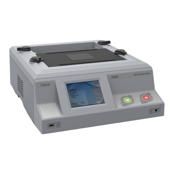
Page 35: Front Panel Description
Press this button to stop running a test program. A red indicator will illuminate around the button when measurements have been stopped. (5) Power Indicator This indicates that the power supply to the instrument is switched on. AT5600 User Manual 98-119 issue 14 Page 35... - Page 36 Separate sense and power connections allow for four wire (Kelvin) connections to the part under test so that test fixture connections are not included in the measurements. AT5600 User Manual 98-119 issue 14 Page 36...
-
Page 37: Rear Panel Description
(2) Safety Interlock Supplied protected by a cover plate, this connects to a safety device, such as a light curtain. When the connection is broken the AT5600 cannot produce any dangerous voltages. HIGH VOLTAGE MAY BE PRESENT (<=400Vpk). See chapter 6, Safety Systems. To gain access to the port, remove the cover plate... - Page 38 O V E R V I E W Removal and Replacement of a Cover Plate (4) Remote Port The Remote Port is used to electrically signal the status and control the AT5600 allowing external indicators (Running/Pass/Fail) and control inputs (Run/Stop). For more information see 10.3.3...
- Page 39 C H A P T E R – S Y S T E M O V E R V I E W AT5600 User Manual 98-119 issue 14 Page 39...
- Page 40 (9) Server Port This RS232 serial port if used for connection to a computer system running the Voltech AT Series Server software. It is normally only used for legacy connections where an AT5600 is being used to replace an AT3600 or ATi.
-
Page 41: Air Circulation
O V E R V I E W 2.6. Air Circulation The AT5600 has air vents in both sides that draw in and expel air to keep the internal components cool. These vents must not be obstructed. Do not place any other equipment within 50mm of all vent openings. -
Page 42: Tilt Feet
O V E R V I E W 2.7. Tilt Feet To improve the visibility of test pins under certain operator seating arrangements, or to give the AT5600 the same tilt as the AT3600, the rear feet may be tilted. Tilting the feet 2.8. Lifting Points Two lifting points (one for each hand) are provided beneath each side vent. -
Page 43: A Typical Installation
(See chapter 14, AT Series Editor Software) • Requires no software programming skills or expertise. • Test conditions may be entered manually or chosen automatically by measuring a sample transformer. • Up to 50 user tests per program. AT5600 User Manual 98-119 issue 14 Page 43... -
Page 44: Test Fixture
2.9.3. Test Fixture The test fixture acts as an interface between the spring probes of the AT5600 and the part under test. They can be made to order or easily customized from standard fixture kits to allow fast and efficient contacts to be made. See Chapter 13, Test Fixtures. -
Page 45: Using The At5600
3. Using the AT5600 3.1. Usage Overview The following activities must be carried out to use the AT5600 to test components. Create a test fixture. The fixture is required to reliably connect the component under test to the AT5600. Develop a test program. Use the AT Editor software to develop a suitable test program for the component under test. -
Page 46: Test Fixtures
PCB mounting and flying lead transformers. 4. A single test fixture can be used for all transformers wound on the same bobbin. As well as the standard fixture system, custom fixtures are available from Voltech partners. Please see the Voltech website www.voltech.com for more information. -
Page 47: Creating Test Programs - At Editor
The Test Program Editor supplied with the AT5600 allows the creation of test programs simply and easily without any need for software programming skills. Each test required for the program is selected from a list of ‘available tests’ by clicking with the mouse. - Page 48 Programs are stored on the Server for later retrieval. For full details of the AT Editor Software, see section 14, AT Series Editor Software. AT5600 User Manual 98-119 issue 14 Page 48...
-
Page 49: Utilizing Editor Test Programs
‘production’ use. Store the program in the AT Server program directory once a program has been developed. It shall then be made available to the AT5600 to load up and be ready to run through the AT5600 user interface. - Page 50 With the Editor and Server installed on the same PC, configuring the Server to use the same default program folder as the Editor is recommended. This way all the test programs are immediately available for use by the Editor and Server. AT5600 User Manual 98-119 issue 14 Page 50...
-
Page 51: Results Printing
A T 5 6 0 0 3.5. Results Printing The AT5600 can be configured to automatically print results at the end of each program run and the results can be printed using the PRINT soft-key through the user interface as detailed in Section 8. - Page 52 A T 5 6 0 0 1. The report title 2. The serial number of the AT5600 that is printing this report. 3. AT5600 Firmware Version. 4. The operator name as entered at the start of the batch. This line is omitted if no operator name has been entered.
-
Page 53: Recommended Configuration
• Usually requires an additional PC (which could be a portable) to be attached locally to (the USB or Auxiliary Port) one of the AT testers when a new program needs to be developed and evaluated • . AT5600 User Manual 98-119 issue 14 Page 53... -
Page 54: Operating The At5600 In Production Test
In robotic situations, the tester's Remote Port provides signals for control systems. For interface details see 10.3.3 The AT5600 shall be connected to a Server PC to allow the option for full statistical process control – results can be used to adjust and check manufacturing parameters. -
Page 55: At5600 Functional Description
4. AT5600 Functional Description 4.1. Behind the Front Panel It is not necessary to understand the operation of the AT5600, but it may be of interest as well as helping to understand its capabilities and to troubleshoot measurement problems. The internal functionality of the AT5600 tester is summarized below:... -
Page 56: Relay Switching Matrix
The purpose of the relay-switching matrix is to connect the selected test source and measurement circuits to the nodes required in the test. The matrix is a crucial component in the performance of the AT5600. It is made up of very advanced, high speed, high voltage reed relays, capable both of holding off the 7000V test voltages used in Hi Pot tests, and of accurately switching the very small voltages and currents encountered in other tests. -
Page 57: Measurement Circuits
= 5V * [500 / (500 + 50)] = 4.55 V 4.1.5. Measurement Circuits The AT5600 tester contains a variety of circuits, capable of performing all the following measurements: • Voltages from less than 1mV to greater than 7000V • Currents from nano-amps to amps •... -
Page 58: Touch Screen & Buttons
4.1.7. Interfaces The AT5600 Interfaces include the USB ports, Ethernet, Remote, Auxiliary, User Port and Server Ports. See section 10.3 for full interface specifications. AT5600 User Manual 98-119 issue 14... -
Page 59: How Does The At5600 Tester Run A Test
D E S C R I P T I O N 4.2. How Does the AT5600 Tester Run a Test? Programming of each test is done at a high level; it is not strictly necessary for you to know the details of how tests are executed within the tester. However, for some users this subject may be of interest, therefore a brief explanation has been included here. - Page 60 C H A P T E R – A T 5 6 0 0 F U N C T I O N A L D E S C R I P T I O N AT5600 User Manual 98-119 issue 14 Page 60...
-
Page 61: Getting Started
For operation of the AT5600, a safety interlock must be properly connected as detailed in chapter 6, Safety Systems. For Demo Units; The AT5600 shall indicate how many days the unit will remain activated for use on the Touch Panel Display top level menu. -
Page 62: Quick Start Tutorial
5.4. Quick Start Tutorial After you have installed the AT5600 together with the editor and server software packages as described in section 5.2 and 5.3, you may wish to follow through this tutorial to familiarize yourself with the system operation. - Page 63 This time place the winding on the right-hand side of the screen, a mirror image of the first winding, and use different terminal names (e.g. ‘C’ and ‘D’). The screen should then look like this: AT5600 User Manual 98-119 issue 14 Page 63...
-
Page 64: Creating The Test Program
Resistance of winding AB (1 M to 209 m) Resistance of winding CD (171 m to 209 m) Inductance of winding AB (>330 uH) (1:1 2%) Turns ratio AB to CD AT5600 User Manual 98-119 issue 14 Page 64... - Page 65 The schematic window showing the two windings. Right side: The available tests window listing all the tests available on your AT5600. (Any test that is not available shall be grayed-out). Lower left: The Program window displaying the tests programmed so far.
- Page 66 171 m and 209 m) > Click to enter just a minimum value (for example, > 171 m), < Click to enter just a maximum value (for example < 209 m). AT5600 User Manual 98-119 issue 14 Page 66...
- Page 67 (Leave as the default - Medium) High terminal C Low terminal D Minimum 20 m Maximum 171 m Click on the ‘OK’ button. Again, the test and its parameters will appear in the ‘Program’ window. AT5600 User Manual 98-119 issue 14 Page 67...
- Page 68 Finally, add the fourth test by double clicking the left mouse button, select ‘TR Turns Ratio’ from the ‘Available Tests’ window. At the dialogue box, enter the data required for the turns ratio test: Voltage Frequency 50 Hz Integration (Leave as the default - Medium) AT5600 User Manual 98-119 issue 14 Page 68...
- Page 69 The lower left window should now contain the complete program. The scroll bars in this window enable you to view each test in the program in turn to check that it is correct. AT5600 User Manual 98-119 issue 14 Page 69...
- Page 70 From the Top Level ‘Part’ menu, select ‘Save As’, At the dialogue box, type in TUTORIAL as the part name. Click on the OK button to close the dialogue box and save the test program in the editor default directory. AT5600 User Manual 98-119 issue 14 Page 70...
-
Page 71: Running The Program From The Editor
5.4.3. Running the Program from the Editor Having created the test program, it is now ready to run on your AT5600 under the control of the Editor. Before proceeding further, make sure that the AT5600 has been powered on and communications are correctly configured in the editor (see 14.3.3). -
Page 72: Transferring The Program To The Server
5.4.4. Transferring the Program to the Server The Voltech Server software is supplied with every AT5600. The use of the Server software is required for handling and storage of test results and is recommended for handling large numbers of different test programs. - Page 73 Server program directory. (note- the At Server allows you to change the program store directory, so check where the AT SERVER has the programs folder specified. This example shown is just the default directory. AT5600 User Manual 98-119 issue 14 Page 73...
- Page 74 2. Loading a program from the server: A full description of the Front Panel operation is given in Chapter 8. Using the front panel of the AT5600, from the top-level menu, tap the soft-key EXECUTE to change to the following display:...
- Page 75 S T A R T E D Select the program from the list or tap the data entry box on the main screen. Enter the Part Number or the program name TUTORIAL in our example. AT5600 User Manual 98-119 issue 14 Page 75...
- Page 76 Connect the transformer to the fixture and press the Run button. When the tester has finished testing, the result shall be displayed as shown; 4. Viewing the Results: To view the test results, tap the RESULTS soft-key; you will see the following display: AT5600 User Manual 98-119 issue 14 Page 76...
-
Page 77: Usb Printer Setup
S T A R T E D 5.5. USB Printer Setup The AT5600 can be configured to automatically print the test results at the end of each program run and the results. Automatic printing is configured as part of the test program using the Editor software. - Page 78 5. Press the Feed button, for less than one second, three times. This will access Mode 3. Customize Value Settings. Then press and hold the Feed button for more than one second. The printer shall print the following; AT5600 User Manual 98-119 issue 14 Page 78...
- Page 79 8. Press the Feed button, for less than one second, two times. This will set the printer to Printer Class. Then press and hold the Feed button for more than one second. The printer shall print the following; AT5600 User Manual 98-119 issue 14 Page 79...
- Page 80 9. At this point, the changes to the setting have been saved and you can turn off the printer. The print is now ready for use. 10. Plug the printer into the Front or Rear USB ‘A’ port on the AT5600. If the printer is configured correctly, the system will display the Printer icon on the front panel as shown below.
-
Page 81: Safety Systems
With this in mind, the rear panels of the AT5600 and some AT accessories have been designed with a safety interlock connector, which is described in the user manual of those products. -
Page 82: Recommended Safety Systems
The light curtain is positioned in front of the AT5600, the light curtain barrier extends well beyond the width of the tester so that the operator is not impeded when he/she has to load and unload the transformer under test. -
Page 83: Constructing Your Own Safety System
3) The safety signals may be switched using Safety electromechanical relays, contactors, or any other switches operated by a device that detects an operator has breached the safety barrier(s). Voltech can supply a pre-made cable suitable for integrating the AT with your own system Part number 250-030... -
Page 84: Safety Notices
6.3. Safety Notices Operator Safety It is the responsibility of the user to ensure that the AT5600 and its associated safety systems are installed, maintained, and operated in accordance with all safety guidance and legislation that may be locally in force. - Page 85 3 A control box, containing the power supply circuits, the switching electronics and the interface to the tester. The interconnection between each of the modules is via simple multi-way cables, which are easy for you to install. Typical installation is shown below AT5600 User Manual 98-119 issue 14 Page 85...
-
Page 86: The At5600 Safety System User Interface
The AT5600 safety system user interface This section describes the various operating and warning messages that may be observed on the AT5600 when it is being used with a safety light curtain. Please consult the documentation supplied with your safety system for its own operating instructions. -
Page 87: Constructing Safe Fixtures
This ensures that the safety system has had time to de-energize the component under test before the user's hand has reached the component or it's connections. 6.7. DC1000 DC Bias Current Source When operating the DC1000A(s) with the AT5600, For Safety Requirements refer to DC1000A User Manual (98-102). 6.8. AC Interface Fixture When operating the AC Interface Fixture with the AT5600, For Safety Requirements refer to AC Interface Fixture User Manual (98-072). - Page 88 C H A P T E R – S A F E T Y S Y S T E M S AT5600 User Manual 98-119 issue 14 Page 88...
-
Page 89: Tests And Test Conditions
USB-B port, launch the AT Editor. Tests which are not available for use shall be grayed-out in the Available Tests window. If you have purchases an AT5600 Standard, you will find you only have 14 of the tests installed. Please contact Voltech if you wish to purchase tests that are not available. -
Page 90: Low Voltage Tests
Turns Ratio by As with Turns Ratio All windings Check windings have Inductance but used where there correct turns and is poor flux linkage phasing between windings. AT5600 User Manual 98-119 issue 14 Page 90... - Page 91 Selected Windings Finds phase shift Phase Angle transformers between Voltage and Current on a winding. PHAS Interwinding Audio & telecom Selected Windings Measures phase shift Phase Test transformers between a pair of windings AT5600 User Manual 98-119 issue 14 Page 91...
-
Page 92: High Voltage Tests
One winding Correct core material. WATT transformers Properly assembled Stress Wattage Line frequency & One Winding (Usually Checks integrity of STRW High Frequency the primary) inter-turn insulation, Transformers the magnetic material and joints AT5600 User Manual 98-119 issue 14 Page 92... -
Page 93: Dc1000 Tests
ZB test. These tests require the use of one or more Voltech DC1000 Precision DC Bias Current Sources. Contact your Voltech sales office for details. 7.1.4. AC INTERFACE Tests Test... -
Page 94: Self-Resonant Frequency
Note that stray fixture capacitance will add to the capacitance of the component and reduce the SRF. Performing compensation will remove the effect of stray fixture capacitance on the measurement of capacitance but cannot remove its effect on SRF. AT5600 User Manual 98-119 issue 14 Page 94... -
Page 95: Explanation Of Integration
The larger the number of sub-measurements (n) the smaller will be the relative standard error, but the greater the time to get a result. The AT5600 provides for AT5600 User Manual 98-119 issue 14 Page 95... - Page 96 For production testing, test limits are usually sufficiently wide to allow short (and occasionally medium) integration to be chosen, and this will result in the shortest possible test times. AT5600 User Manual 98-119 issue 14 Page 96...
-
Page 97: Cty - Continuity
CTY maintains compatibility with the AT5600, but with no speed advantage as the AT5600 is much faster than the AT3600, therefore an R Test is recommended rather than the CTY Test. -
Page 98: R - Winding Resistance
Maximum Value - Specify limit as tightly as possible to ensure that correct wire has been used. Minimum Value - Not usually so critical - can be set to any value that ensures that there is no solder splash causing a short circuit between pins. AT5600 User Manual 98-119 issue 14 Page 98... - Page 99 V=R*100u Where: V = Volts (V) I = Current (A) Ω) R = Resistance ( Please also see 14.6.2 for specific advice on programming the test, and 10.2.1 for test accuracy specification AT5600 User Manual 98-119 issue 14 Page 99...
-
Page 100: Rls Or Rlp - Equivalent Series Or Parallel Resistance
7.7.2 Table 2, based on the value of the inductance of the winding under test. Please also see 14.6.3 for specific advice on programming the test, and 10.2.2 for test accuracy specification AT5600 User Manual 98-119 issue 14 Page 100... -
Page 101: Ls Or Lp - Inductance (Series Or Parallel Circuit)
LS or LP - Inductance (Series or Parallel Circuit) Where Used The AT5600 offers two basic alternative ways to confirm that the transformer has been assembled properly, with the appropriate number of primary and secondary turns, the right grade of magnetic material for the core, and the correct air gap if required. - Page 102 In general, high values of inductance will have a high inter-turn capacitance and hence a low resonant frequency. Where there is a choice of test frequencies always use the lower value, to minimize any problems due to self-resonance. Non-linear inductance AT5600 User Manual 98-119 issue 14 Page 102...
- Page 103 This can be a problem when trying to compare measurements made on commercially available impedance bridges, or component testers, with measurements made using the AT5600. The test signal in such bridges is usually determined within the instrument and is often at a fixed frequency and at a voltage level which is not guaranteed to be constant for all value of inductance.
-
Page 104: Lsb Or Lpb-Inductance With Bias Current (Series Or Parallel Circuit)
Parallel Circuit) Where Used With the LSB and LPB tests, the AT5600 offers two further ways to confirm that the transformer has been assembled properly, with the appropriate number of turns, the right grade of magnetic material for the core, and the correct air gap if required. -
Page 105: Ql - Quality Factor
Section 7.7.2 Table 2, based on the value of the inductance of the winding under test. Please also see 14.6.6 for specific advice on programming the test, and 10.2.3 for test accuracy specification AT5600 User Manual 98-119 issue 14 Page 105... -
Page 106: D - Dissipation Factor Or Tan
For optimum accuracy and performance, use the test conditions chosen for capacitance in a later section of this chapter. Please also see 14.6.7 for specific advice on programming the test, and 10.2.3 for test accuracy specification AT5600 User Manual 98-119 issue 14 Page 106... -
Page 107: Ll - Leakage Inductance
1 Amp flowing in the shorted secondary winding. To protect transformer windings, the test current when measuring leakage inductance is limited in the table to 50mA maximum. AT5600 User Manual 98-119 issue 14 Page 107... - Page 108 In this case, the user offset may be required to fully remove the errors. Please also see 14.6.8 for specific advice on programming the test, and 10.2.2 for test accuracy specification AT5600 User Manual 98-119 issue 14 Page 108...
-
Page 109: C - Interwinding Capacitance
AT5600 User Manual 98-119 issue 14 Page 109... - Page 110 Non-linear Capacitance Normally non-linearity in the stray capacitance of transformers are not a problem, and therefore capacitance is measured with as large a voltage as possible. AT5600 User Manual 98-119 issue 14 Page 110...
- Page 111 The tester always uses a parallel equivalent circuit for capacitance measurements. Please also see 14.6.9 for specific advice on programming the test, and 10.2.2 for test accuracy specification AT5600 User Manual 98-119 issue 14 Page 111...
-
Page 112: Tr - Turns Ratio
7.13. TR - Turns Ratio Where Used The AT5600 offer two basic alternative ways to confirm that the transformer has been assembled properly, with the appropriate number of primary and secondary turns. Turns ratio is the preferred test for signal, pulse and switched mode power transformers, where the normal operating conditions require only small excursions of the B-H curve, never extending beyond the linear regions. - Page 113 Next, energize a secondary winding (possibly at a different voltage and / or frequency depending on its inductance) and measure the turns ratio between the various primaries. In this way windings, which should be matched are treated equally during the test. AT5600 User Manual 98-119 issue 14 Page 113...
- Page 114 Please consider the following two examples which illustrate this point. A, Best Practice set up All the LO terminals are defined as “A” The secondary is at the LO end of A-C ; SEC LO is at 0V AT5600 User Manual 98-119 issue 14 Page 114...
- Page 115 C O N D I T I O N S B, NON-OPTIMAL set up – avoid this configuration. The secondary is at the HI end of A-C, hence SEC LO is not at 0V, potentially causing a common mode effect. AT5600 User Manual 98-119 issue 14 Page 115...
- Page 116 (i.e. 11:10 or 10:11), and therefore limits of +5% and -5% would be suitable to detect the error. Please also see 14.6.10 for specific advice on programming the test, and 10.2.4 for test accuracy specification AT5600 User Manual 98-119 issue 14 Page 116...
-
Page 117: Trl - Turns Ratio By Inductance
7.14. TRL - Turns Ratio by Inductance Where Used The AT5600 offers two basic alternative ways to confirm that the transformer has been assembled properly, with the appropriate number of primary and secondary turns. Turns ratio is the preferred test for signal, pulse and switched mode power transformers, where the normal operating conditions require only small excursions of the B-H curve, never extending beyond the linear regions. - Page 118 (i.e. 11:10 or 10:11), and therefore limits of +5% and -5% would be suitable to detect the error. Please also see 14.6.11 for specific advice on programming the test, and 10.2.5 for test accuracy specification AT5600 User Manual 98-119 issue 14 Page 118...
-
Page 119: Z, Zb - Impedance, Impedance With Bias
The test voltage is applied to the input winding, and the voltage and current measured. From the measured results the impedance is calculated. Please also see 14.6.12 for specific advice on programming the test, and 10.2.23 for test accuracy specification AT5600 User Manual 98-119 issue 14 Page 119... -
Page 120: R2 - Dc Resistance Match
Use the PC Editor’s ‘Measure’ button (together with a sample part) if you are unsure of the resistance values. Please also see 14.6.2 for specific advice on programming the test, and 10.2.18 for test accuracy specification AT5600 User Manual 98-119 issue 14 Page 120... -
Page 121: L2 - Inductance Match
Compensation can be used to eliminate these errors. The following table suggests suitable test conditions for different values of expected average inductance: AT5600 User Manual 98-119 issue 14 Page 121... - Page 122 Where there is a choice of test frequencies always use the lower value, to minimize any problems due to self-resonance. Please also see 14.6.13 for specific advice on programming the test, and 10.2.18 for test accuracy specification AT5600 User Manual 98-119 issue 14 Page 122...
- Page 123 Note that, for any given winding, the inductance values for two circuits are not necessarily the same; this should be born in mind when specifying the test limits. AT5600 User Manual 98-119 issue 14 Page 123...
-
Page 124: C2 - Capacitance Match
100pF 100KHz → 100pF 10KHz → 10nF 1KHz → 10nF 100nF 100Hz → The Test Conditions for Capacitance Match Measurement When choosing the test conditions, the following potential problems should be considered: AT5600 User Manual 98-119 issue 14 Page 124... - Page 125 Generally, this will present no problems, as on most transformers the difference between the two values is usually negligible and can be ignored. Please also see 14.6.14 for specific advice on programming the test, and 10.2.18 for test accuracy specification AT5600 User Manual 98-119 issue 14 Page 125...
-
Page 126: Gbal - General Longitudinal Balance
GBAL dialogue box has a separate group of terminals X and Y for the first and second measurements respectively. The preferred method of measurement is the LBAL test for which Voltech provide a separate test specifically for this measurement. This test is suitable for audio & telecommunication transformers and checks the effective common mode rejection ratio of the transformer. - Page 127 C O N D I T I O N S 1) Preferred method (the method of the LBAL test, used by many transformer manufacturers) Measurement Energized Measured 2) IEEE 455 method (used in Canada, Europe and ROW) Measurement Energized Measured AT5600 User Manual 98-119 issue 14 Page 127...
- Page 128 GBAL = 20 log | VM1 / VM2 | + (optionally) compensation for test fixture scaling Please also see 14.6.15 for specific advice on programming the test, and 10.2.19 for test accuracy specification AT5600 User Manual 98-119 issue 14 Page 128...
-
Page 129: Lbal - Longitudinal Balance
LBAL – Longitudinal Balance Where Used The longitudinal balance test is Voltech's preferred method to measure what is effectively the Common Mode Rejection Ratio of a transformer designed to connect to a balanced line. Two measurements are performed each by applying a voltage to the transformer and measuring the resulting voltage to calculate the CMRR. -
Page 130: Ilos - Insertion Loss
(specified by the user in the test dialogue), the insertion loss is calculated. Please also see 14.6.17 for specific advice on programming the test, and 10.2.20 for test accuracy specification AT5600 User Manual 98-119 issue 14 Page 130... -
Page 131: Resp - Frequency Response
ILOS results are outside the specified limits, the RESP result is the preferred ILOS result that is furthest away from the limit. Please also see 14.6.18 for specific advice on programming the test, and 10.2.21 for test accuracy specification AT5600 User Manual 98-119 issue 14 Page 131... -
Page 132: Rlos - Return Loss
(specified by the user in the test dialogue), the return loss is calculated. The impedances used are complex, where Please also see 14.6.19 for specific advice on programming the test, and 10.2.22 for test accuracy specification AT5600 User Manual 98-119 issue 14 Page 132... -
Page 133: Angl - Impedance Phase Angle
30A → 1k 10k 300A → 100 1k → 10 0.5V 10mA 100 → 1 100mV 50mA 10 → 100m 10mV 50mA 1 50mA 100 m→ 10m 10 m → 1m 50mA AT5600 User Manual 98-119 issue 14 Page 133... -
Page 134: Phas - Interwinding Phase Test
→ 0.5V 100 10 → 100mV 10 1 → 10mV 1 100m → 100m 10m Please also see 14.6.21 for specific advice on programming the test, and 10.2.25 for test accuracy specification AT5600 User Manual 98-119 issue 14 Page 134... -
Page 135: Out - Output To User Port
Therefore, if the settings are required for one part of the test program only, 2 OUT tests will be required, 1 to turn the appropriate relay drivers on and 1 to turn them back off. Please also see 14.6.22 for specific advice on programming the test, AT5600 User Manual 98-119 issue 14 Page 135... -
Page 136: Ir - Insulation Resistance
In many cases, specifying a lower value will speed up the execution of the test. A value of 100M is generally suitable for most applications. Please also see 14.6.23 for specific advice on programming the test, and 10.2.11 for test accuracy specification AT5600 User Manual 98-119 issue 14 Page 136... -
Page 137: Hpdc - Dc Hi-Pot (Eht)
IEC742 has been replaced by IEC61558, which specifies 1 second for production testing. Details are available on the IEC web-site (http://www.iec.ch) Please also see 14.6.24 for specific advice on programming the test, and 10.2.12 for test accuracy specification AT5600 User Manual 98-119 issue 14 Page 137... -
Page 138: Hpac - Ac Hi-Pot (Eht)
In programming the AT5600 you may select the voltage (from 100V to 5kVrms), the frequency (50Hz / 60Hz at the full voltage, or up to 1kHz at reduced voltage), the current trip level (10A to 30mA peak), and the ramp up and dwell times, all to... - Page 139 This method complies with the production requirements of EN61558-1 (1998), UL1411, 5 Edition and others. Please also see 14.6.25 for specific advice on programming the test, and 10.2.13 for test accuracy specification AT5600 User Manual 98-119 issue 14 Page 139...
-
Page 140: Surg - Surge Stress Test
More impulses may also help find defective wire insulation. For multiple impulses, The AT5600 will return the LOWEST result of all the impulses programmed. For each impulse, the AT5600 will charge an internal capacitor to the programmed test voltage. - Page 141 C O N D I T I O N S Transient Analysis During the decay phase after the impulse has been fired, the AT5600 measures both the voltage amplitude along the transient, and the time of decay. The AC waveform (and frequency/amplitude/decay rate) is a function of the characteristics of your UUT and the AT5600 Capacitors used to discharge the DC spike.
- Page 142 Volt/turn ratio. To prevent damage to the UUT, or to the AT5600, the SURG test should always be applied to the winding with the greatest number of turns. You should also check that the design of the other windings that will be energized can withstand the induced voltage.
- Page 143 300%) your nominal mVs for this effect to be seen so is unlikely to even be seen by most users. Please also see 14.6.26 for specific advice on programming the test, and 10.2.17 for test accuracy specification AT5600 User Manual 98-119 issue 14 Page 143...
-
Page 144: Watt - Wattage
During the Wattage test, a constant, user specified AC voltage is applied across the winding in question. All other windings are held open circuit during this test. The AT5600 measures the voltage across and current through the winding. The Wattage is the product of the in-phase components of the current and voltage. -
Page 145: Watx - Wattage (External Source)
This test uses an external source to provide the test signal which must be coupled to the tester via a Voltech AC Source Interface (contact your supplier for details). See the AC Source Interface user manual or the Editor help system for details of how to configure external AC sources for use with an AT5600. - Page 146 Trimming of requested Voltage (when using Step-up transformer with AC Interface) When using the AC interface with a step-up transformer, the AT5600 uses the Class D drive (used on VOC MAGI WATT and STRW) and routes it thought the AC interface. The AT5600 calculates a nominal value for the voltage needed to get the target value based on your requested voltage, and the programmed ratio of your chose transformer.
-
Page 147: Strw - Stress Watts
This breakdown is detected by an increase in the measured power. Note: Maximum power for this test is 25W Please also see 14.6.29 for specific advice on programming the test, and 10.2.15 for test accuracy specification AT5600 User Manual 98-119 issue 14 Page 147... -
Page 148: Strx - Stress Watts (External Source)
See the AC Source Interface user manual or the Editor Help system for details of how to configure external AC sources for use with an AT5600. This test is suitable for large line frequency bobbin wound and some HF transformers. It checks the integrity of inter-turn insulation, the magnetic material and joints at higher than the normal operating voltage. - Page 149 Trimming of requested Voltage (when using Step-up transformer with AC Interface) When using the AC interface with a step-up transformer, the AT5600 uses the Class D drive (used on VOC MAGI WATT and STRW) and routes it thought the AC interface. The AT5600 calculates a nominal value for the voltage needed to get the target value based on your requested voltage, and the programmed ratio of your chose transformer.
-
Page 150: Magi - Magnetizing Current
To give you repeatable accurate results, the measurement does not start until any transient has settled. In addition, to give you the quickest test execution time, the AT5600 uses a switch- on sequence which minimizes such transient effects. - Page 151 C O N D I T I O N S Specifying the Test Limits The AT5600 offers you two ways to specify the test limits: • Using a true RMS measurement (the most common method) • Using a mean-sense measurement that is scaled to RMS for sine waves...
-
Page 152: Magx - Magnetizing Current (External Source)
MAGX - Magnetizing Current (External Source) Where Used The AT5600 offers two basic alternative ways to confirm that the transformer has been assembled properly, with the appropriate number of primary and secondary turns, the right grade of magnetic material for the core, and the correct air gap if required. - Page 153 Trimming of requested Voltage (when using Step-up transformer with AC Interface) When using the AC interface with a step-up transformer, the AT5600 uses the Class D drive (used on VOC MAGI WATT and STRW) and routes it thought the AC interface. The AT5600 calculates a nominal value for the voltage needed to get the target value based on your requested voltage, and the programmed ratio of your chose transformer.
-
Page 154: Voc - Open Circuit Voltage
7.37. VOC - Open Circuit Voltage Where Used The AT5600 offers two basic alternative ways to confirm that the transformer has been assembled properly, with the appropriate number of primary and secondary turns. Open circuit voltage measurements are the preferred tests for line frequency transformers, designed to operate over the full extent of the B-H curve, including the non-linear regions. - Page 155 In this case the AT EDITOR dialog box will ask for a Nominal Voltage. The AT uses this nominal voltage as a starting position for testing. The AT5600 will then attempt to trim V to get the exact value current that is needed.
-
Page 156: Vocx - O/C Voltage (External Source)
7.38. VOCX - O/C Voltage (External Source) Where Used The AT5600 offers two basic alternative ways to confirm that the transformer has been assembled properly, with the appropriate number of primary and secondary turns. Open circuit voltage measurements are the preferred tests for line frequency transformers, designed to operate over the full extent of the B-H curve, including the non-linear regions. - Page 157 Trimming of requested Voltage (when using Step-up transformer with AC Interface) When using the AC interface with a step-up transformer, the AT5600 uses the Class D drive (used on VOC MAGI WATT and STRW) and routes it thought the AC interface. The AT5600 calculates a nominal value for the voltage needed to get the target value based on your requested voltage, and the programmed ratio of your chose transformer.
-
Page 158: Lvoc - Low Voltage Open Circuit
B-H curve, never extending beyond the linear region. On the AT5600, high voltage open circuit tests (VOC or VOCX) are available for testing line frequency transformers at their operating point (up to 270V, 1 kHz and 2A). - Page 159 → 50Hz 100H → 100H 50Hz → 20Hz 10kH → The test conditions can also be determined automatically by the AT5600 according to this table: Voltage Specified Auto Auto Frequency Specified Specified Auto Note that a ‘fixed’ voltage signal cannot be used with an ‘Auto’ frequency.
-
Page 160: Ilk - Leakage Current Test
The voltage and frequency applied are normally the operating voltage and frequency of the transformer. Please also see 14.6.36 for specific advice on programming the test, and 10.2.26 for test accuracy specification AT5600 User Manual 98-119 issue 14 Page 160... -
Page 161: Lsbx - Inductance With External Bias (Series Circuit)
IR HPAC, HPDC, DCRT, ACRT, DCVB or ACBV in the same program. The AT5600 and AT Editor will check for this and warn you if you are attempting to do this. The AT3600 and old AT Editor did not give this warning, but it is still a valid best practice for the AT3600. -
Page 162: Lpbx - Inductance With External Bias (Parallel Circuit)
IR HPAC, HPDC, DCRT, ACRT, DCVB or ACBV in the same program. The AT5600 and AT Editor will check for this and warn you if you are attempting to do this. The AT3600 and old AT Editor did not give this warning, but it is still a valid best practice for the AT3600. -
Page 163: Zbx - Impedance With External Bias
IR HPAC, HPDC, DCRT, ACRT, DCVB or ACBV in the same program. The AT5600 and AT Editor will check for this and warn you if you are attempting to do this. The AT3600 and old AT Editor did not give this warning, but it is still a valid best practice for the AT3600. -
Page 164: Acrt - Ac Hi-Pot Ramp
The voltage and current are monitored throughout the ramp time. In programming the AT5600 you may select the voltage (from 100V to 5.5kVrms), the frequency (50Hz / 60Hz at the full voltage, or up to 1 kHz at reduced voltage), the current trip level (10A to 5mApeak), and the ramp up times (1 to 30sec), all... -
Page 165: Dcrt - Dc Hi-Pot Ramp
If the maximum monitored current is exceeded before the target voltage is reached the test has "Failed". Please also see 14.6.41 for specific advice on programming the test, and 10.2.30 for test accuracy specification AT5600 User Manual 98-119 issue 14 Page 165... -
Page 166: Acvb - Ac Voltage Break Down
The voltage will ramp to the specified maximum plus 50V. In programming the AT5600 you may select the voltage (from 100V to 5kVrms), the frequency (50Hz / 60Hz at the full voltage, or up to 1 kHz at reduced voltage), the current trip level (10A to 5mApeak), and the ramp up times (1 to 30sec), all... -
Page 167: Dcvb - Dc Voltage Break Down
The voltage will ramp to the specified maximum plus 50V. In programming the AT5600 you may select the voltage (from 100V to 7kV DC), the current trip level (10A to 1mA), and the ramp up times (1 to 2sec), all to suit the specification of the transformer under test. - Page 168 C H A P T E R – T E S T S A N D T E S T C O N D I T I O N S AT5600 User Manual 98-119 issue 14 Page 168...
-
Page 169: Front Panel Operation
Introduction 8.1.1. The Touch Screen Display The AT5600 has a colour touch screen display. Light finger pressure will activate any touch sensitive area. The format of the screen display is similar throughout the menu system and consists of a screen title at the top, a main window on the left, and a soft-key area on the right. -
Page 170: Run And Stop Buttons
8.1.3. User Input User input can be made into the AT5600 using the touch screen, buttons, or other accessories connected to available interface ports. The touch screen provides the ability to tap and select items, and to display a soft keyboard for typing. -
Page 171: Splash Screen
8.1.5. Power On Once the AT5600 has initialized and powered up, it will wait for user input. This is the top-level menu for access to all the major functions available. PART LIST Load a test program from AT SERVER software RESUME re-load the last test program if “FINISH”-ed accidentally... -
Page 172: Part List
• SYNC P/N LIST – Gets a fresh list of programs from the AT Server. This list (but NOT the actual program) is stored in the AT5600 so only needs SYNC if the list changes. This speeds up navigation. The actual ATP test program will always be fetched from the Server, never stored in the unit. -
Page 173: Entering A Part Number
The program name can be typed (or partially typed) at the keyboard or selected from the list. Tap the soft-key ACCEPT when program is selected. You can clear any selection by clicking on the “X” to the right of the selection box AT5600 User Manual 98-119 issue 14 Page 173... - Page 174 Note that these options are part of the program, not global settings for the AT, allowing you to enable different options for each transformer as required. If you have chosen to enable any of these, then on program load, the following screen will be shown. AT5600 User Manual 98-119 issue 14 Page 174...
-
Page 175: Serial Number
Remember to create enough leading zeros, if you are going to exceed the number of digits – see examples below etc. ATY678 ATY679 ATY680 ATY681 etc. RFR998 RFR999 RFR000 RFR001 etc. RFR0998 RFR0999 RFR1000 RFR1001 etc. AT5600 User Manual 98-119 issue 14 Page 175... -
Page 176: Batch
Enter the batch number for the transformer under test then tap the ACCEPT soft- key. The BACKSPACE soft-key will clear the last character entered. The “X”in the entry field will clear the whole text AT5600 User Manual 98-119 issue 14 Page 176... -
Page 177: Operator
Tap the OPERATOR soft-key; you will see the following display: Enter the OPERATOR NAME then tap the ACCEPT soft-key. The BACKSPACE soft-key will clear the last character entered. The “X”in the entry field will clear the whole text AT5600 User Manual 98-119 issue 14 Page 177... -
Page 178: Compensation
The screen also confirms if you have successfully compensated the program since the program was loaded. These show as “Applied” Use the active soft keys to enter the sub menu- for each compensation type. AT5600 User Manual 98-119 issue 14 Page 178... - Page 179 Follow the on-screen instruction then tap the RUN button, the short circuit compensation shall begin. When the AT5600 has completed the short circuit compensation process, the following screen will appear. Tap the BACK soft-key to return to the previous menu.
- Page 180 Follow the on-screen instruction then tap the RUN button to run the open circuit compensation. Tap the BACK soft-key to return to the previous menu. When the AT5600 has completed the open circuit compensation process, the following screen will appear.
- Page 181 When the LOAD soft-key is tapped, the following screen shall appear: Follow the on-screen instruction then tap the RUN button to run Load compensation. When the AT5600 has completed the load compensation process, the following screen will appear. Tap the BACK soft-key to return to the previous menu.
-
Page 182: Run Screen
O P E R A T I O N R u n S c r e e n Once a program is loaded into the AT5600, connect the transformer to the fixture and press the Run button to begin testing the transformer. When testing is complete, you will see the following display: •... -
Page 183: Results
PAGE UP used to scroll up the list PAGE DOWN used to scroll down the list PRINT used to print the results if USB printer attached BACK Return to testing mode AT5600 User Manual 98-119 issue 14 Page 183... -
Page 184: Self-Test
Before commencing system test, please ensure that there is no fixture fitted and nothing is touching any of the test nodes on the top surface of the AT5600. The self-test shall only run if the Safety Interlock is in the safe condition. - Page 185 BACK – return to main menu If there is a failure found in the self-test, follow the instruction outlined in section 14.8 for a listing of the results and contact your Voltech supplier for service. AT5600 User Manual 98-119 issue 14...
-
Page 186: Set Up
O P E R A T I O N 8.1.8. SET UP Set up allows the adjustment of the AT5600 options that effect the way the unit runs tests and stores results. You may change the System parameter at any time. Tap the SET UP soft-key in the top-level screen. -
Page 187: Sound
The SOUND soft-key changes the way the internal Beeper sounds or to turn off the sound for functions such as Failure indicator, Pass indicator, Soft-keyboard sound ACCEPT change the internal beeper settings CANCEL return to the previous screen, without accepting the changes AT5600 User Manual 98-119 issue 14 Page 187... -
Page 188: Clock
Set the time and date accordingly then tab the ACCEPT to save changes and returns to the previous screen ACCEPT save the changes and returns to the previous screen BACKSPACE clear the last character entered. CANCEL return to the previous screen without accepting changes AT5600 User Manual 98-119 issue 14 Page 188... -
Page 189: Server
TCP/IP(Ethernet.) If you choose TCP/IP for Ethernet, then enter the IP of the PC running the AT SERVER software. ACCEPT save changes and return CANCEL return to the previous screen without changes. AT5600 User Manual 98-119 issue 14 Page 189... -
Page 190: Network
O P E R A T I O N 8.1.12. NETWORK This soft-key allow the user to configure the way the AT5600 connects to your internal network, if using Ethernet. When the DHCP is selected the AT5600 shall acquire an available IP address from your network automatically. -
Page 191: Unit Info
F R O N T P A N E L O P E R A T I O N 8.1.13. UNIT INFO This page displays basic unit information BACK to return to previous screen AT5600 User Manual 98-119 issue 14 Page 191... -
Page 192: Status Bar Icons
Third is the COMMUNICATIONS icon. This is shown when the unit is communicating with the AT SERVER to send test results, or when the AT is being controlled by the AT EDITOR. AT5600 User Manual 98-119 issue 14 Page 192... -
Page 193: Testing Wound Components
8.2. Testing Wound Components 8.2.1. A Typical Workflow The below shows the basic test execution flow, and the possible sequence of user inputs (set in the AT EDITOR program options) during testing. AT5600 User Manual 98-119 issue 14 Page 193... -
Page 194: Traceability
A) printed to USB printer And/or B) Saved with any results to CSV, MS SQL or MS ACCESS, if the Save Results to the Server option is enabled in the ATP program. AT5600 User Manual 98-119 issue 14 Page 194... -
Page 195: Stop On Fail Function
“false” FAIL results caused by misconnection from being recorded to the Server. It can also save time on longer test programs with genuine fails. See below for description of this functionality. AT5600 User Manual 98-119 issue 14 Page 195... -
Page 196: Getting The Results
If the “Send results to Server” program option has been set, then the results will be sent back and recorded in the server software. AT5600 User Manual 98-119 issue 14 Page 196... - Page 197 14.5.1) then a printout will automatically be sent to the USB printer. The PRINT soft-key can also be used to manually trigger a print of the results, even if printing is not enabled in the test program. AT5600 User Manual 98-119 issue 14 Page 197...
- Page 198 C H A P T E R 8 – F R O N T P A N E L O P E R A T I O N AT5600 User Manual 98-119 issue 14 Page 198...
-
Page 199: Troubleshooting
If the self-test fails, then a list of all the failure that the self-test found shall be listed in the Results. If the AT5600 fails, the Self-Test then please contact your nearest Voltech service center or Voltech technical support providing the details of the self-test failures. -
Page 200: Editor Error Codes
0003 (i.e., both bits 0 and 1 are set, so the binary value is 0000000000000011). If a test has been interrupted, then an additional code is set in bits 12-15 of the status code. AT5600 User Manual 98-119 issue 14 Page 200... - Page 201 An over-temperature interrupt has terminated the test; unit has become too hot. An auxiliary fault interrupt has terminated the test; this can be created by an accessory attached to the peripheral port. Unit rebooted during the test sequence. AT5600 User Manual 98-119 issue 14 Page 201...
-
Page 202: Correcting Errors
See section 10.3.5 for details of the safety interlock interface. 9.2.2. Temperature error If the AT5600 gets too hot, then an error message indicating an Over Temperature shall be displayed in the error message window. Overheating can be caused by many factors;... -
Page 203: Voltage Present Error
AT5600 for any faults. If the AT5600 is found not to be faulty then the cause of this error must either; 1. An external source connected incorrectly 2. - Page 204 C H A P T E R – T R O U B L E S H O O T I N G AT5600 User Manual 98-119 issue 14 Page 204...
-
Page 205: 10. Specifications
C H A P T E R – S P E C I F I C A T I O N S Chapter 10. Specifications 10.1. Specification Summary AT5600 User Manual 98-119 issue 14 Page 205... - Page 206 3 MHz 0.20% Bias Impedance ° ° ° ANGL -360 1 mV 20 Hz 3 MHz 0.05 Phase Inter-winding ° ° ° PHAS -360 1 mV 20 Hz 3 MHz 0.05 Phase AT5600 User Manual 98-119 issue 14 Page 206...
- Page 207 20 Hz 0.10% Source) Wattage (Ext. 5 kHz WATX 100 mW 6 kW 600 V 20 Hz Source) Stress 5 kHz STRX Wattage (Ext. 100 mW 6 kW 600 V 20 Hz Source) AT5600 User Manual 98-119 issue 14 Page 207...
- Page 208 +/- 100 uA +/- (2.5% +/- 0.01% / kHz) of test signal. Tests in BOLD MAGX VOCX WATX STRX - for use with AC INTERFACE. LSBX LPBX ZBX - for use with DC1000 / DC1000A. AT5600 User Manual 98-119 issue 14 Page 208...
-
Page 209: Accuracy Specifications - Available Tests
- Maximum Ω Ω Ω Ω- Ω Ω <1 -10k >50k Resistance R Test current I=1/R V=R*100u Where: V = Volts (V) I = Current (A) Ω) R = Resistance ( AT5600 User Manual 98-119 issue 14 Page 209... -
Page 210: Ls, Lp, Rls, Rlp, Ll And C Tests
= 0.08 % + (0.2 % ∗ �� (������ ������ & ������) �� ��) where: is the test frequency (Hz) is the measured voltage (V) is the measured current (A) is the measured Q factor AT5600 User Manual 98-119 issue 14 Page 210... -
Page 211: Ql And D Tests
�� �� �� = 0.2 % ∗ [�� )] (������ �� ������������) ���� �� �� �� where: is the measured current (A) is the measured Q factor is the measured D factor AT5600 User Manual 98-119 issue 14 Page 211... -
Page 212: Tr Test
= 0.1 % + ( �� �� �� where: is the test frequency (Hz) is the measured primary voltage (V) is the measured secondary voltage (V) is the measured turns ratio (Primary/Secondary) AT5600 User Manual 98-119 issue 14 Page 212... -
Page 213: Trl Test
(%) is the accuracy of the secondary inductance (%) To calculate the accuracies of the primary and secondary inductances, use the formula for LS accuracy given in 10.2.2. AT5600 User Manual 98-119 issue 14 Page 213... -
Page 214: Magi Test
�� �� �� 0.01 % �� = 0.03 % + ( ) + (2.0 % ∗ �� �� �� �� �� where: is the test frequency (Hz) is the measured current (A) AT5600 User Manual 98-119 issue 14 Page 214... -
Page 215: Magx Test (External Source)
(Hz) is the measured current (A) During a MAGX test the AT5600 automatically applies the test voltage to the part under test and checks that the voltage has stabilized before recording measurements. The time that the voltage takes to stabilize will vary with the source type used and the nature of the part under test. -
Page 216: Voc Test
= 0.08 % + ( 0.001 % ∗ �� �� �� �� 0.01 % �� = 0.03 % + ( �� �� �� where: is the test frequency (Hz) is the measured voltage (V) AT5600 User Manual 98-119 issue 14 Page 216... -
Page 217: Vocx Test (External Source)
(Hz) is the measured voltage (V) During a VOCX test the AT5600 automatically applies the test voltage to the part under test and checks that the voltage has stabilized before recording measurements. The time that the voltage takes to stabilize will vary with the source type used and the nature of the part under test. -
Page 218: Lvoc Test
= 0.08 % + ( 0.00001 % ∗ �� �� �� �� 0.01 % �� = 0.03 % + ( �� �� �� where: is the test frequency (Hz) is the measured voltage (V) AT5600 User Manual 98-119 issue 14 Page 218... -
Page 219: Ir Test
= 3.20 % + ( �� �� �� = 0.5 % + ( 0.001 % ∗ �� �� �� �� where: is the measured current (A) is the measured IR value (M) AT5600 User Manual 98-119 issue 14 Page 219... -
Page 220: Hpdc Test
(%) is the correction for current level (%) where: �� = 3.20 % �� �� = 0.08 % �� 0.0001 % �� �� �� �� where: is the measured current (A) AT5600 User Manual 98-119 issue 14 Page 220... -
Page 221: Hpac Test
�� = 3.00 % �� �� = 0.08 % + 0.001 % ∗ ���� �� 0.001 % �� �� �� �� where: is the measured current (A) is the test frequency (Hz) AT5600 User Manual 98-119 issue 14 Page 221... -
Page 222: Lsb And Lpb Tests
= 0.08 % + ( �� �� �� where: is the test frequency (Hz) is the measured voltage (V) is the measured current (A) is the bias current (A) is the measured Q factor AT5600 User Manual 98-119 issue 14 Page 222... -
Page 223: Watt And Strw Tests
(A) is the power factor of the load and: �� ���� = ���� where: is the measured power (W) is the product of test voltage and magnetizing current AT5600 User Manual 98-119 issue 14 Page 223... -
Page 224: Watx And Strx Tests (External Source)
(W) is the product of MAGX and VOCX results When performing either of these tests, the AT5600 automatically applies the test voltage to the part under test and checks that the voltage has stabilized before recording measurements. The time that the voltage takes to stabilize will vary with the source type used and the nature of the part under test. -
Page 225: Surg Test
For UUTs with Ls => 125uH, the unit maximum is achievable, namely 5000V DC For UUTs with Ls<=125uH, the maximum voltage achievable is defined by Vout = (7000 * Luut) / (Luut + 50) Where Luut = UUT Series Inductance in uH AT5600 User Manual 98-119 issue 14 Page 225... -
Page 226: L2, C2 And R2 Tests
Y measurement (%) Refer to the accuracy specifications for the LS, C and R tests to determine the accuracy of the X and Y measurements (10.2.2 and 10.2.1). AT5600 User Manual 98-119 issue 14 Page 226... -
Page 227: Gbal Test
= 0.1 + (0.000001 ∗ �� �� �� 0.01 ���� �� ���� �� ���� 0.01���� �� ���� �� ���� where: is the test frequency (Hz) is the measured input voltage (V) is the measured output voltage (V) AT5600 User Manual 98-119 issue 14 Page 227... -
Page 228: Lbal And Ilos Tests
�� �� 0.01 ���� �� ���� �� ���� 0.01 ���� �� ���� �� ���� where: is the test frequency (Hz) is the measured input voltage (V) is the measured output voltage (V) AT5600 User Manual 98-119 issue 14 Page 228... -
Page 229: Resp Test
�� �� 0.01 ���� �� ���� �� ���� 0.01 ���� �� ���� �� ���� where: is the test frequency (Hz) is the measured input voltage (V) is the measured output voltage (V) AT5600 User Manual 98-119 issue 14 Page 229... -
Page 230: Rlos Test
�������� and: is the measured voltage (V) is the measured current (A) is the real part of the reference impedance () real is the imaginary part of the reference impedance () imag AT5600 User Manual 98-119 issue 14 Page 230... -
Page 231: Z And Zb Test
) + [0.03 % ∗ ( �� �� �� �� �� where: is the test frequency (Hz) is the measured voltage (V) is the measured current (A) is the bias current (A) AT5600 User Manual 98-119 issue 14 Page 231... -
Page 232: Angl Test
0.01 �� = 0.03 + �� �� �� 0.000003 �� = 0.03 + �� �� �� where: is the test frequency (Hz) is the measured voltage (V) is the measured current (A) AT5600 User Manual 98-119 issue 14 Page 232... -
Page 233: Phas Test
�� = 0.05 ∗ (|�� − |) ������ �� �� ���� where: is the test frequency (Hz) is the measured primary voltage (V) is the turns ratio between the primary and secondary AT5600 User Manual 98-119 issue 14 Page 233... -
Page 234: Ilk Test
= 0.1 % + ( 0.001 % ∗ �� �� �� �� 0.00001 % �� = 0.1 % + ( �� �� �� where: is the test frequency (Hz) is the measured current (A) AT5600 User Manual 98-119 issue 14 Page 234... -
Page 235: Lsbx And Lpbx Tests
= 0.08 % + ( �� �� �� where: is the test frequency (Hz) is the measured voltage (V) is the measured current (A) is the bias current (A) is the measured Q factor AT5600 User Manual 98-119 issue 14 Page 235... -
Page 236: Zbx Test
) + [0.03 % ∗ ( �� �� �� �� �� where: is the test frequency (Hz) is the measured voltage (V) is the measured current (A) is the bias current (A) AT5600 User Manual 98-119 issue 14 Page 236... -
Page 237: Acrt Test
�� = 3.0 % + ( �� �� �� 0.001 % �� �� �� �� where: is the measured voltage (Vrms) is the maximum test current (Arms) is the test frequency (Hz) AT5600 User Manual 98-119 issue 14 Page 237... -
Page 238: Dcrt Test
= 0.08 % �� 500 % �� = 3.0 % + ( �� �� �� 0.0001 % �� �� �� �� where: is the actual voltage (V) is the maximum test current (A) AT5600 User Manual 98-119 issue 14 Page 238... -
Page 239: Acvb Test
Special Notes: Under certain test conditions the measured current will be higher than the allowed minimum limit due to parasitic effects on the AT5600 and any connected fixture system. This works out to be 12.5 uA at 2.5 KV @ 50Hz. -
Page 240: Dcvb Test
= 0.08 % �� 500 % �� = 3.0 % + ( �� �� �� 0.0001 % �� �� �� �� where: is the actual voltage (V) is the maximum test current (A) AT5600 User Manual 98-119 issue 14 Page 240... -
Page 241: Interface Specifications
No connection As RS232 is now a legacy protocol for communications, it’s it highly likely that customers using RS232 on the AT5600 will use a USB to RS232 converter to interface with your PC. As the AT5600 generates high voltages and is commonly used in environments where high voltage and EMC noise is present, we recommend using an optically ISOLATED USB-RS232 converter. -
Page 242: Remote Port
!STOP Input (Pin 9) The !STOP input is an active Lo input with an internal pull-up resistor. The active-going edge of this input halts all AT5600 activity, turning off all signal sources. To use this with an ‘emergency stop’ switch, wire the switch between this input and 0V. - Page 243 All the outputs are fitted with 1k protection resistors, and therefore they cannot directly drive external high current loads such as indicators, or bin-select relays. Beep Output (Pin 1) This is an active Hi output which copies the internal beeper. AT5600 User Manual 98-119 issue 14 Page 243...
-
Page 244: Peripheral Interface
S P E C I F I C A T I O N S 10.3.4. Peripheral Interface This interface is for connection only to an approved Voltech accessory. Do not try to make other connections to this interface as damage may occur. 15-pin female D-type connector... -
Page 245: Safety Interlock
There are 3 active circuits on the safety interlock connector. Two are digital control circuits, and the third is a high voltage analog circuit. ALL three circuits must be correctly made before the AT5600 will run any tests. Once the Safety interlock has been connected, the AT5600 can produce voltages that should be considered lethal. -
Page 246: User Port
10.3.6. User Port The User Port is positioned on the rear panel of the AT5600 and contains six open-collector relay drive outputs, and two HC MOS compatible inputs. The relay drives are switched on and off by the OUT test, inserted into your test program sequence. - Page 247 User Relay Drive Outputs (pins 1, 2, 3, 6, 7, 8) All the User Relay Drive Outputs have the following equivalent circuit: Specification: Relay coil resistance: > 150 Maximum output current: 80 mA per output AT5600 User Manual 98-119 issue 14 Page 247...
-
Page 248: Ethernet Port
Standard USB 2.0 type ‘A’ interfaces used to connect the AT5600 to a printer. 10.3.9. USB ‘B’ Port A standard USB 2.0 type ‘B’ interface used to connect the AT5600 to a PC running the Voltech editor software. AT5600 User Manual 98-119 issue 14... -
Page 249: Environmental Conditions
This ensures the safety of the instrument and the user when normal precautions are followed. Dielectric Strength 1.5 KV AC 50Hz for 1 minute, line input to earth Storage Temperature -40°C to +70°C Operating Temperature +5°C to +40°C Humidity 10% to 80% RH non-condensing AT5600 User Manual 98-119 issue 14 Page 249... -
Page 250: Mechanical
Height: 199mm Depth: 572mm The fixture bay on the top surface of the AT5600 accepts Voltech fixture plates (see chapter 13). The maximum static weight over a 100cm area in the center of a fixture is 5.0Kg AT5600 User Manual 98-119 issue 14... -
Page 251: Emc Compliance
Supplimentary Information: The product herewith complies with the requirements of the EMC Directive 2004/108/EC the Low Voltage Directive 2006/95/EC Signed for on behalf of Voltech Instruments Dr John Ford, Managing Director 21 May 2014 AT5600 User Manual 98-119 issue 14... - Page 252 C H A P T E R – S P E C I F I C A T I O N S AT5600 User Manual 98-119 issue 14 Page 252...
-
Page 253: 11. Maintenance
11.1. Air Filters The AT5600 houses two air filters that filter the air going through its cooling fans. These filters will be cleaned during a service and calibration (if returned to a Voltech service center), and if done annually, this is normally sufficient to maintain the air flow through the instrument. -
Page 254: Removing The Air Filters
Ingun (UK) Ltd Part Number GK S113 204 300 R 1502. The test pins on the bottom of the test fixture can also tarnish with age, and accrue dirt and grease from the manufacturing environment. Voltech recommends Chemtronics Pow-R-Wash VZ for cleaning the test pins/ https://www.chemtronics.com/pow-r-wash-vz 11.3. -
Page 255: 12. Warranty And Service
Customer and that for a period of one year (12 months) from such time Voltech will repair or replace any Product which does not comply with this warranty PROVIDED ALWAYS THAT the Company’s liability... -
Page 256: Service And Calibration
It shall be deemed to exclude all other warranties and conditions whether express or implied and whether arising by common law statute or otherwise. Voltech reserve the right to waive this benefit in any event where it is clear upon inspection that the cause of the failure is due to customer misuse. -
Page 257: Accessories
If you require any cables, fixtures, or fuses in addition to those supplied with your AT5600, please contact your local Voltech supplier. The Voltech part numbers for the parts supplied with your unit are given in the section 1.4 on page 17 of this manual. - Page 258 C H A P T E R – W A R R A N T Y A N D S E R V I C E AT5600 User Manual 98-119 issue 14 Page 258...
-
Page 259: 13. Test Fixtures
The full fixture system user manual part number 98-028 is available from the Voltech website. The AT5600 can perform an extremely comprehensive series of tests on a wide variety of wound components. To utilize this capability fully it is recommended that test fixtures are constructed to suit each part to be tested. -
Page 260: The Voltech Fixture System
13.2.1. Description of the Fixture System The Voltech AT Series fixture system allows you freedom and flexibility when considering your fixturing needs. All fixtures are mounted on fixture boards, which are available as a blank fixture plate and as a fixture kit which contains parts to help you. -
Page 261: Compatible Connection Types
This fixture may be used for convenient wiring to existing fixtures or as a means of connecting flying leads and clips for use in developing test programs or testing parts in a design laboratory. AT5600 User Manual 98-119 issue 14 Page 261... -
Page 262: Making Fixture Connections - Kelvin Connections
The ‘common’ lead length is shown as AA’ and BB’ in the diagram below. AT5600 User Manual 98-119 issue 14 Page 262... - Page 263 SENSE terminals are all on the inside of the fixture area. IMPORTANT: Kelvin four terminal connections are generally advised to be used in all test fixtures but they are essential for impedance measurements less then 1. AT5600 User Manual 98-119 issue 14 Page 263...
-
Page 264: Compensation
In addition to the open and short circuit correction, the AT5600 has been enhanced to provide load correction feature (for certain tests only), similar to high... -
Page 265: Compensation Summary - Available Tests
Insulation Resistance Hi-Pot (DC) HPDC Hi-Pot (AC) HPAC Hi-Pot Ramp (DC) DCRT Hi-Pot Ramp (AC) ACRT Voltage Break down (DC) DCVB Voltage Break down (AC) ACVB Surge Stress SURG Output to User Port AT5600 User Manual 98-119 issue 14 Page 265... -
Page 266: Equipment Required
Nominal Value, is then entered into the test program in the Load Compensation box. The results returned by the AT are then adjusted to compensate any stray parasitic from the system. i.e. Standard Reference Component; AT5600 User Manual 98-119 issue 14 Page 266... - Page 267 Program for Load Compensation) 2. When the AT5600 performs a Load Compensation, it measures say 120 nH. The ratio of Nominal Value / AT Measured Results is stored in the AT5600’s memory as the Load Compensation Ratio. Example, this case 100nH / 120 nH = 0.833.
-
Page 268: General Notes
13.6.1. Beware of High Voltages The AT5600 can apply DC voltages up to 7000 V DC and AC voltages up to 5000 V AC during a test. This must be kept in mind when constructing test fixtures. If possible, always design the fixture with the nodes that experience the same high voltages grouped together. -
Page 269: Kelvin Connections
The test pins on the bottom of the test fixture can also tarnish with age, and accrue dirt and grease from the manufacturing environment. Voltech recommends Chemtronics Pow-R-Wash VZ for cleaning the test pins/ https://www.chemtronics.com/pow-r-wash-vz AT5600 User Manual 98-119 issue 14... - Page 270 C H A P T E R – T E S T F I X T U R E S AT5600 User Manual 98-119 issue 14 Page 270...
-
Page 271: 14. At Series Editor Software
• Test programs and may be stored in a PC running the AT series server. • Transfer of test programs to specified folder paths or external disks. • A full context sensitive and menu driven help system. • Upgrading the firmware inside the AT5600. AT5600 User Manual 98-119 issue 14 Page 271... -
Page 272: Installing The Editor Software
If USB operation is required (as recommended) then download AT5600 USB drivers from the Voltech website and follow the instructions for installing the drivers. After installation, when the AT5600 is connected via the USB port, a virtual COM port will be created through which you can communicate with the AT5600. -
Page 273: Installing The Main Application
‘Language’. In the dialogue box, select the language and the click OK to save. 14.3.3. Communications Configuration Configure the Editor to use the virtual COM Port installed for the AT5600 (see 14.2.2): From the Top Level ‘Setup’ menu, select ‘Communications’. -
Page 274: Schematic Editing
Click the left mouse button to place the winding. 3. When the winding is placed, a dialogue box appears prompting you to name both of the winding’s two terminals. AT5600 User Manual 98-119 issue 14 Page 274... - Page 275 Adding a Terminal to an Existing ” in section 14.4.5. Winding NOTE: Terminal names may be between 1 and 6 characters in length and may contain any upper-case letter or AT Series keyboard character excluding SPACE. AT5600 User Manual 98-119 issue 14 Page 275...
-
Page 276: Connecting The Winding Terminals To Nodes
1. Select a winding by pointing at it with the mouse pointer and clicking the left mouse button once. A selected winding will be indicated by a box surrounding the winding. 2. Choose ‘Delete Winding’ from the ‘Schematic’ menu. The selection will be removed from the screen. AT5600 User Manual 98-119 issue 14 Page 276... -
Page 277: Renaming A Terminal
Upon clicking the left mouse button, a form fill-in dialogue box will appear on the screen with prompts to insert the terminal names of the new winding. AT5600 User Manual 98-119 issue 14 Page 277... -
Page 278: Deleting A Terminal From An Existing Winding
Adding a Core Connection To add a core connection: Choose ‘Add Core Connection’ from the ‘Schematic’ menu. A connection from the core will appear on the screen. You may now add a core-to-node connection. AT5600 User Manual 98-119 issue 14 Page 278... -
Page 279: Deleting A Core Connection
1. Select the connection you wish to delete by pointing at it with the mouse prompt and pressing the left mouse button. 2. Choose ‘Delete Screen Connection’ from the ‘Schematic’ menu. The screen connection will be removed from the schematic. AT5600 User Manual 98-119 issue 14 Page 279... -
Page 280: Creating The Program
After you have created the program schematic, before starting to insert any tests in the program, you should set up which program options you would like to use. From the Top-Level menu bar, select Program > Option; AT5600 User Manual 98-119 issue 14 Page 280... -
Page 281: Results Printing
Failures Only - The results of the tests producing a ‘fail’ result will be printed. Full Reporting - The results for all the tests in the program will be printed out for each transformer tested. AT5600 User Manual 98-119 issue 14 Page 281... -
Page 282: Kelvin Pre-Check
UUT windings. What is Tested Any node (1-20) connected to a winding, core or screen terminal on the schematic is tested once, even if the terminal is not used in a test. AT5600 User Manual 98-119 issue 14 Page 282... - Page 283 RETRY, ignore the failure and CONTINUE with testing, or ignore the failure and CANCEL the testing. In the case of retry and ignore, the execution is resumed by pressing the RUN button. AT5600 User Manual 98-119 issue 14 Page 283...
- Page 284 However, programs with the Kelvin option enabled can still be used on these products, but the flag will simply be ignored. This prevents users from maintaining two separate test programs and maintains ATP program portability between unit types. AT5600 User Manual 98-119 issue 14 Page 284...
-
Page 285: Operator Numbering
Enable this function if you wish the Server archive to contain the results from the additional measurements associated with re-running a program, for example after execution has been halted by the STOP ON FAIL program option. AT5600 User Manual 98-119 issue 14 Page 285... -
Page 286: Stop On Fail
RUN TO END Disable STOP ON FAIL for the rest of the run. Useful if you have a long program with many fails that you wish to let run. AT5600 User Manual 98-119 issue 14 Page 286... -
Page 287: Date And Time On Reports
FAIL, as the requested test conditions were not met. This is analogous to ALC (Auto Level Control) on most popular LCR meters. With this option enabled, the AT5600 will make the PASS/FAIL judgement purely based on the measured parameter and ignore the “0020” error code. -
Page 288: Aql (Acceptable Quality Level)
AQL monitoring is an optional feature of the Voltech PC Server, which displays live summary results from multiple AT testers. When the AQL set here is reached or exceeded, the Server will display a warning. -
Page 289: Fixture Id
Using an external source extends the power and voltage range available. The source must be coupled to the tester via a Voltech AC Source Interface (contact your supplier for details). This option allows you to choose and configure the type of external source you will be using;... -
Page 290: Program Edit
Tests which are not available for use shall be grayed-out. Contact your Voltech sales office to purchase test that not available. See section 14.9 Customize Tester for instruction to upgrade your AT5600 with additional tests. -
Page 291: Adding Tests
Program. As an example, if you wish to add another ‘R Winding Resistance’ to the program: Double click on the ‘R Winding Resistance’ test in Available Test list. Fill in the fields of the dialogue box. AT5600 User Manual 98-119 issue 14 Page 291... -
Page 292: Inserting Tests
This will become the point of insertion; the new test will be inserted in front of the one you have selected. From the Top Level menu bar, select Program > Insert Test; AT5600 User Manual 98-119 issue 14 Page 292... - Page 293 You will now see the dialogue box for the test you wish to insert. Enter the appropriate test data in the fields of the dialogue box, and click on OK. You will now see the new test inserted into the Program. AT5600 User Manual 98-119 issue 14 Page 293...
-
Page 294: Modifying Tests
Make any changes you require to the test data in the fields of the dialogue box, and click on OK. You will now see the test with the modified data in the Program window. AT5600 User Manual 98-119 issue 14 Page 294... -
Page 295: Deleting Tests
From the Top Level menu bar, select Program > Delete Test You will now see the test has been removed from the list in the Program window. AT5600 User Manual 98-119 issue 14 Page 295... -
Page 296: Test Parameters
Note that some tests do not have a Measure button. These are High voltage test, Magnetizing Current, and others. The programming details for each test in section 14.6 (Programming Tests) of this chapter specify which tests allow the use of the Measure button. AT5600 User Manual 98-119 issue 14 Page 296... -
Page 297: Test Limits
The four types of limits for the R- Winding Resistance - test are: The limits are entered as positive and negative percentages about a nominal value. > <: The limits are entered as minimum and maximum values. AT5600 User Manual 98-119 issue 14 Page 297... - Page 298 To choose which type of limit you wish to use, simply use the mouse to click on one of the buttons %, > <, >, or <. AT5600 User Manual 98-119 issue 14 Page 298...
-
Page 299: Using The Measure Button
In fact, most tests have a Measure button within the dialogue box. It is included there to allow you to quickly measure the value from a sample transformer with the AT5600 and to set the limits for that test. Hardware Connections for Using the Measure Button Before attempting to use the Measure button: 1. - Page 300 Assuming no errors, when the tester has finished the compensation measurement, you will be prompted to remove the shorting links, and fit the sample transformer: AT5600 User Manual 98-119 issue 14 Page 300...
- Page 301 0.1 at the specified frequency and you have specified a 5V test signal, then the AT would have to supply 5V / 0.1 = 50 Amps! AT5600 User Manual 98-119 issue 14 Page 301...
- Page 302 Check first that the winding is properly connected to the right nodes. Choose ‘No’ and no conditions will be chosen. See Chapter 7 – Tests and test conditions for suitable values. Also, see 4.1.4 Test Source – Low Power Generator for limitations. AT5600 User Manual 98-119 issue 14 Page 302...
-
Page 303: Verifying Your Program
4. From the Top Level menu bar, select Tester > Download Program The Editor will now download the test program to the tester. After a few seconds, you should see a message to say that the Download was successful. AT5600 User Manual 98-119 issue 14 Page 303... - Page 304 2 …. runs. This is because the AT5600 learns the best generator settings to quickly trim to your requested test conditions. You should find that subsequent runs can be 200-300% faster than the first run, and this is expected and normal.
-
Page 305: Compensation
After you have clicked on the ‘OK’ button at either of the messages, the tester will be commanded to make the compensation measurements for your test program. AT5600 User Manual 98-119 issue 14 Page 305... - Page 306 REMEMBER: Whenever you make changes to the program, the compensation results in the tester will no longer be valid. Make sure to compensate again each time you download a test program to an AT Series Tester. AT5600 User Manual 98-119 issue 14 Page 306...
-
Page 307: Hints And Tips
Safety tests such as Hi-Pot To detect poor interwinding isolation; but this time where safety is an issue, for example, from a primary winding to a secondary winding on a mains isolation transformer. AT5600 User Manual 98-119 issue 14 Page 307... - Page 308 The resulting ATP program file can then be moved to your chosen program storage folder on the PC, or a network drive, for use by the AT SERVER. Program File Names can be up to 20 characters’ long AT5600 User Manual 98-119 issue 14 Page 308...
-
Page 309: Test Grouping
Tests can be programmed in any order you wish, and the results for each individual test will be independent of where they are in the program. However, the AT5600 has 6 different power sources, and to get the best speed execution time we recommend that tests are grouped using the following table. - Page 310 General Longitudinal Balance ACRT Hi-Pot Ramp AC ACVB Hi-Pot Voltage Breakdown AC DCRT Hi-Pot Ramp DC DCVB Hi-Pot Voltage Breakdown DC HPAC Hi-Pot AC HPDC Hi-Pot DC Leakage Current Insulation Resistance SURG Surge Stress AT5600 User Manual 98-119 issue 14 Page 310...
-
Page 311: Programming Tests
E D I T O R 14.6. Programming Tests This section describes in more detail how to fill in the data for the dialogue boxes for each of the tests available for your AT5600. AT5600 User Manual 98-119 issue 14 Page 311... -
Page 312: Cty - Continuity
If any winding has a resistance greater than 10k, then choose a value bigger than that expected for the winding with the largest resistance. 2. Select OK. The test specification will then be displayed in the program window. AT5600 User Manual 98-119 issue 14 Page 312... -
Page 313: R - Winding Resistance
R - Winding Resistance 14.6.2. To check that the resistance of a winding is correct, the AT5600 applies a DC test signal to the selected winding. It then measures both the current through and the voltage across the winding, and calculates the resistance. -
Page 314: Rls Or Rlp - Equivalent Series Or Parallel Resistance
The measured voltage is divided by the current to obtain a complex impedance and the equivalent series or parallel resistance calculated. Select either ‘RLS Equivalent Series Resistance’ or ‘RLP Equivalent Parallel Resistance’ from the Available Tests window, to display: AT5600 User Manual 98-119 issue 14 Page 314... - Page 315 < Enter just a maximum value. Note: The Measure button may be used here as outlined in section 14.5.9. 5. Select OK. The test specification will then be displayed in the program window. AT5600 User Manual 98-119 issue 14 Page 315...
-
Page 316: Ls Or Lp - Winding Inductance (Series Or Parallel Circuit)
On selecting ‘LS Inductance (series cct)’ or ‘LP Inductance (parallel cct)’ from the Available Tests window, a dialogue box will be displayed. To program the test: 1. Enter the signal and frequency required for the test. AT5600 User Manual 98-119 issue 14 Page 316... - Page 317 < Enter just a maximum value. Note: The Measure button may be used here as outlined in section 14.5.9. 5. Select OK. The test specification will then be displayed in the program window. AT5600 User Manual 98-119 issue 14 Page 317...
-
Page 318: Lsb Or Lpb - Inductance With Bias (Series Or Parallel Circuit)
On selecting ‘LSB Inductance with Bias (Series cct)’ or ‘LPB Inductance with Bias (Parallel cct)’ from the Available Tests window, a dialogue box will be displayed. AT5600 User Manual 98-119 issue 14 Page 318... - Page 319 Enter just a maximum value. Note: The Measure button may be used here as outlined in section 14.5.9. 5. Select OK. The test specification will then be displayed in the program window. AT5600 User Manual 98-119 issue 14 Page 319...
-
Page 320: Ql - Quality Factor
4. Select (mouse click the button) the type of limits you require and enter the values. % Enter a nominal value and then the limits as negative and positive AT5600 User Manual 98-119 issue 14 Page 320... - Page 321 < Enter just a maximum value. Note: The Measure button may be used here as outlined in section 14.5.9. 5. Select OK. The test specification will then be displayed in the program window. AT5600 User Manual 98-119 issue 14 Page 321...
-
Page 322: D - Dissipation Factor Or Tan
< A maximum value only Note: The Measure button may be used here as outlined in section 14.5.9. 5. Select OK. The test specification will then be displayed in the program window. AT5600 User Manual 98-119 issue 14 Page 322... -
Page 323: Ll - Leakage Inductance
By clicking on the arrow to the right of the fill-in box, you will be provided with a choice of possible terminals. Double-click on the name of the required terminal. 4. Select the secondary high and low terminals. AT5600 User Manual 98-119 issue 14 Page 323... - Page 324 In this case, the user offset may be required to fully remove the errors. 9. Select OK. The test specification will then be displayed in the program window. AT5600 User Manual 98-119 issue 14 Page 324...
-
Page 325: C - Interwinding Capacitance
C H A P T E R E D I T O R 14.6.9. C - Interwinding Capacitance Your AT5600 can test the capacitance present between windings, screens and core. Select ‘C Interwinding Capacitance’ from the list of available tests, to give the following dialogue box: To program the test: 1. -
Page 326: Tr - Turns Ratio
E D I T O R 14.6.10. TR - Turns Ratio You may program the AT5600 Tester to test the turns ratio between one winding and any other. To measure turns ratio, a test source voltage is applied to one winding, the energized winding, and the voltages across two other windings (one of which may also be the energized winding) are measured using harmonic analysis. - Page 327 6. If required, the polarity of the test can be checked. Click on the expected polarity of the transformer turns, otherwise disable the test by selecting ‘No Test’. 7. Select OK. The test specification will be displayed in the program window on the screen. AT5600 User Manual 98-119 issue 14 Page 327...
- Page 328 In this case set a limit of 0 (pri) and ½ (sec). This will result in equivalent limits of 19 and 21. Ideal for detecting an error of 1 turn or more. AT5600 User Manual 98-119 issue 14 Page 328...
- Page 329 This is why a combination of inductance and turns ratio tests are normally used to confirm the correct assembly of transformers. The polarity test may be selected as (+)ve, (-)ve or no test. To measure the exact interwinding phase angle use the PHAS test. AT5600 User Manual 98-119 issue 14 Page 329...
-
Page 330: Trl - Turns Ratio (By Inductance)
Click the required terminal.) Select the high and low terminals of the secondary winding. AT5600 User Manual 98-119 issue 14 Page 330... - Page 331 5. If required, the polarity of the test can be checked. Click on the expected polarity of the transformer turns, otherwise disable the test by selecting ‘No Test’. 6. Select OK. The test specification will be displayed in the program window on the screen. AT5600 User Manual 98-119 issue 14 Page 331...
-
Page 332: Z, Zb - Impedance
'Short' will test at the maximum speed, but may give a slightly noisier reading. See 7.3 Explanation of Integration. 3. Enter the terminal names between which the impedance is to be measured. See terminal selection. AT5600 User Manual 98-119 issue 14 Page 332... - Page 333 Note: The Measure button may be used here as outlined in section 14.5.9. 5. For the impedance with bias test, you may also select a DC bias current. 6. Select OK. The test specification will then be displayed in the program window. AT5600 User Manual 98-119 issue 14 Page 333...
-
Page 334: L2 - Inductance Match
5. Set the inductance ratio limits. Note: The Measure button may be used here as outlined in section 14.5.9. 6. Select OK. The test specification will then be displayed in the program window. AT5600 User Manual 98-119 issue 14 Page 334... -
Page 335: C2 - Capacitance Match
4. Selecting Terminals [Y] prompts a second dialogue box allowing the second set of windings to be configured for the test. 5. Set the capacitance limits. Note: The Measure button may be used here as outlined in section 14.5.9. AT5600 User Manual 98-119 issue 14 Page 335... - Page 336 C H A P T E R E D I T O R 6. Select OK. The test specification will then be displayed in the program window. AT5600 User Manual 98-119 issue 14 Page 336...
-
Page 337: Gbal - General Longitudinal Balance
GBAL dialogue box has a separate group of terminals X and Y for the first and second measurements respectively. The preferred method of measurement is the LBAL test for which Voltech provide a separate test specifically for this measurement. This test is suitable for audio & telecommunication transformers and checks the effective common mode rejection ratio of the transformer. - Page 338 7. Since components on the test fixture may scale measured readings the "Compensate for Test Fixture Scaling" allows the test to account for this. 8. Select OK. The test specification will then be displayed in the program window. AT5600 User Manual 98-119 issue 14 Page 338...
-
Page 339: Lbal - Longitudinal Balance
14.6.16. LBAL – Longitudinal Balance The longitudinal balance test is Voltech's preferred method to measure what is effectively the Common Mode Rejection Ratio of a transformer designed to connect to a balanced line. Two measurements are performed each by applying a voltage to the transformer and measuring the resulting voltage to calculate the CMRR. -
Page 340: Ilos - Insertion Loss
> Enter just a minimum value. Note: The Measure button may be used here as outlined in section 14.5.9. 6. Select OK. The test specification will then be displayed in the program window. AT5600 User Manual 98-119 issue 14 Page 340... -
Page 341: Resp - Frequency Response
5. Add test frequencies as required by entering the frequency and clicking 'add'. See Chapter 7. 6. Set the frequency response limits. 7. Select OK. The test specification will then be displayed in the program window. AT5600 User Manual 98-119 issue 14 Page 341... -
Page 342: Rlos - Return Loss
Enter just a minimum value. Note: The Measure button may be used here as outlined in section 14.5.9. 4. Select OK. The test specification will then be displayed in the program window. AT5600 User Manual 98-119 issue 14 Page 342... -
Page 343: Angl - Impedance Phase Angle
Z (impedance) test to check the complex impedance presented to the transformers input and output. On selecting “ANGL Impedance Phase Angle” from the ‘available tests’ window, the following dialogue box will be displayed: AT5600 User Manual 98-119 issue 14 Page 343... - Page 344 Note: The Measure button may be used here as outlined in section 14.5.9. 5. Select ‘OK’. The test specification will then be displayed in the program window. AT5600 User Manual 98-119 issue 14 Page 344...
-
Page 345: Phas - Interwinding Phase Test
On selecting "PHAS Interwinding Phase" from the 'available tests' window, the following dialog box is displayed: AT5600 User Manual 98-119 issue 14 Page 345... - Page 346 Note: The Measure button may be used here as outlined in section 14.5.9. 5. Select ‘OK’. The test specification will then be displayed in the program window. AT5600 User Manual 98-119 issue 14 Page 346...
-
Page 347: Out - Output To User Port
14.6.22. OUT – Output to User Port The User Port on the AT5600 has 6 ‘Relay Driver’ outputs associated with it. The OUT test allows programming of the User Port relay driver outputs to perform additional relay switching as part of the test program. -
Page 348: Ir - Insulation Resistance
1 mA. The Measure button may be used here as outlined in section 14.5.9. 5. Select OK. The test specification will then be displayed in the program window. AT5600 User Manual 98-119 issue 14 Page 348... -
Page 349: Hpdc - Dc Hi-Pot (Eht)
Used list; then click the ‘< Remove’ button to transfer it back to the Available list). 3. Enter the maximum current value in the bottom section. 4. Select OK. The test specification will then be displayed in the program window. AT5600 User Manual 98-119 issue 14 Page 349... -
Page 350: Hpac - Ac Hi-Pot (Eht)
3. Enter the maximum current value in the bottom section. Note that the current is the peak value, not an RMS. 4. Select OK. The test specification will then be displayed in the program window. AT5600 User Manual 98-119 issue 14 Page 350... -
Page 351: Surg - Surge Stress Test
1. Enter the desired test voltage. 2. Enter either a nominal winding inductance or select AUTO mode. When a fixed inductance is entered, the AT5600 uses this value to estimate the frequency and duration of the transient waveform and thus determine the digital waveform sampling rate that is used. - Page 352 6. If required, enter the load compensation value as outlined in section 13.5. 7. Select OK. The test specification will then be displayed in the program window. AT5600 User Manual 98-119 issue 14 Page 352...
-
Page 353: Watt - Wattage
4. Enter the maximum wattage value in the bottom section. The Measure button may be used here as outlined in section 14.5.9. 5. Select OK. The test specification will then be displayed in the program window. AT5600 User Manual 98-119 issue 14 Page 353... -
Page 354: Watx - Wattage (External Source)
Voltech AC Source Interface (contact your supplier for details). See the AC Source Interface user manual or the Editor help system for details of how to configure external AC sources for use with an AT5600. -
Page 355: Strw - Stress Wattage
2. Select the Dwell time you require. 3. Enter the names of the Hi and Lo terminals. 4. Set maximum power limit. 5. Select OK. The test specification will then be displayed in the program window. AT5600 User Manual 98-119 issue 14 Page 355... -
Page 356: Strx - Stress Watts (External Source)
This test uses an external source to provide the test signal which must be coupled to the tester via a Voltech AC Source Interface (contact your supplier for details). See the AC Source Interface user manual or the Editor help system for details of how to configure external AC sources for use with an AT5600. -
Page 357: Magi - Magnetizing Current
< Enter just a maximum value. Note: The Measure button may be used here as outlined in section 14.5.9. 6. Select OK. The test specification will then be displayed in the program window. AT5600 User Manual 98-119 issue 14 Page 357... -
Page 358: Magx - Mag. Current (External Source)
This test uses an external source to provide the test signal which must be coupled to the tester via a Voltech AC Source Interface (contact your supplier for details). See the AC Source Interface user manual or the Editor help system for details of how to configure external AC sources for use with an AT5600. -
Page 359: Voc - Open Circuit Voltage
On selecting ‘VOC Open Circuit Voltage’ from the available tests window, the following form-fill dialogue box will be displayed: To program the test: 1. Enter the test voltage and test frequency. AT5600 User Manual 98-119 issue 14 Page 359... - Page 360 7. Select OK. The test specification will then be displayed in the program window. AT5600 User Manual 98-119 issue 14 Page 360...
-
Page 361: Vocx - O/C Voltage (External Source)
This test uses an external source to provide the test signal which must be coupled to the tester via a Voltech AC Source Interface (contact your supplier for details). See the AC Source Interface user manual or the Editor help system for details of how to configure external AC sources for use with an AT5600. - Page 362 7. Select OK. The test specification will be displayed in the program window on the screen. AT5600 User Manual 98-119 issue 14 Page 362...
-
Page 363: Lvoc - Low Voltage Open Circuit
The Measure button may be used here as outlined in section 14.5.9. Test limits should be set as close as possible to the nominal value in order to detect faults. A typical tolerance would be 5%. AT5600 User Manual 98-119 issue 14 Page 363... -
Page 364: Ilk - Leakage Current Test
5. Select ‘OK’. The test specification will then be displayed in the program window. AT5600 User Manual 98-119 issue 14 Page 364... -
Page 365: Lsbx - Inductance With External Bias (Series Circuit)
0.2% @ Q>10 to 1000A This test requires the use of one or more Voltech DC1000 Precision DC Bias Current Sources. Contact your Voltech sales office for details. The inductance of a transformer winding while an external bias current is flowing through it may be tested using series or parallel equivalent circuit models. - Page 366 < Enter just a maximum value. The Measure button may be used here as outlined in section 14.5.9. 5. Select OK. The test specification will then be displayed in the program window. AT5600 User Manual 98-119 issue 14 Page 366...
-
Page 367: Lpbx - Inductance With External Bias (Parallel Circuit)
0.2% @ Q>10 to 1000A This test requires the use of one or more Voltech DC1000 Precision DC Bias Current Sources. Contact your Voltech sales office for details. The inductance of a transformer winding while an external bias current is flowing through it may be tested using series or parallel equivalent circuit models. - Page 368 < Enter just a maximum value. The Measure button may be used here as outlined in section 14.5.9. 5. Select OK. The test specification will then be displayed in the program window. AT5600 User Manual 98-119 issue 14 Page 368...
-
Page 369: Zbx - Impedance With External Bias
0.2% to 1000A This test requires the use of one or more Voltech DC1000 Precision DC Bias Current Sources. Contact your Voltech sales office for details. The Winding Impedance with External Bias test measures the impedance of a selected winding while applying a DC current from the DC1000 through the winding. - Page 370 < Enter just a maximum value. The Measure button may be used here as outlined in section 14.5.9. 5. Select OK. The test specification will then be displayed in the program window. AT5600 User Manual 98-119 issue 14 Page 370...
-
Page 371: Acrt - Ac Hi-Pot Ramp
Note that the current is the peak value, not an RMS. 4. Select the user offset enabled, if required and enter the voltage value. 5. Select OK. The test specification will then be displayed in the program window. AT5600 User Manual 98-119 issue 14 Page 371... -
Page 372: Dcrt - Dc Hi-Pot Ramp
4. Enter the maximum current value in the bottom section. 5. Select the user offset enabled, if required and enter the voltage value. 6. Select OK. The test specification will then be displayed in the program window. AT5600 User Manual 98-119 issue 14 Page 372... -
Page 373: Acvb - Ac Voltage Break Down
3. Enter the maximum voltage value in the bottom section. 4. Select the user offset enabled, if required and enter the voltage value. 5. Select OK. The test specification will then be displayed in the program window. AT5600 User Manual 98-119 issue 14 Page 373... -
Page 374: Dcvb - Dc Voltage Break Down
3. Enter the maximum current value in the bottom section. 4. Select the user offset enabled, if required and enter the voltage value. 5. Select OK. The test specification will then be displayed in the program window. AT5600 User Manual 98-119 issue 14 Page 374... -
Page 375: Firmware Upgrades
E D I T O R 14.7. Firmware Upgrades The firmware of the AT5600 controls how tests are carried out, which tests are available and how the interfaces (including the front panel) function. New versions of the firmware are made available periodically and electronic copies are available free of charge. -
Page 376: Self-Test
Before commencing system test, please ensure that there is no fixture fitted and nothing is touching any of the test nodes on the top surface of the AT5600. The self-test shall only run if the Safety Interlock is in the safe condition. - Page 377 A prompt shall be displayed when the Self-Test is complete, as shown below. g) If the self-test detects a failure, a Self-Test Fail shall pop-up, contact your Voltech supplier for service. Please include the self-test log file, SelfTest.xml, with your inquiry for service.
-
Page 378: Customize Tester
To determine which test are available, connect the AT5600 to a PC via AUX port or USB-B port, launch the AT Editor, select Program > Edit, tests which are not available for use shall be grayed-out in the Available Tests window. -
Page 379: 15. At Series Server Software
4. Viewing of test programs outside the test program editor environment 5. Test results may be received and stored in a database ready format for easy offline analysis 6. OLE 2 support allowing real-time analysis of your production test system AT5600 User Manual 98-119 issue 14 Page 379... -
Page 380: Installing The Server Software
C H A N G E L O G 15.2. Installing the Server Software All software is available from the Voltech website www.voltech.com. 15.2.1. Computer Requirements Before attempting to install any Windows software, check that the PC satisfies the following hardware requirements:... -
Page 381: Starting For The First Time
When the installation of the software has been completed, you will see the Server icon in the program group ‘Voltech Software’. Double-click this icon with the left mouse button to start the program. The first time the program runs it will show the communications configuration screen. -
Page 382: Setting Up The Options
The communications configuration dialog may be displayed when the software starts up or by using the Setup > Communications option from the Server menu There are two methods for communicating with the AT5600. The recommended method is using a Ethernet network connection. - Page 383 AT series tester. Highlight the open channel, and then click the Remove button in to remove the open channel and close the results window. AT5600 User Manual 98-119 issue 14 Page 383...
- Page 384 C H A N G E L O G Network Communications The recommended method for communicating with an AT5600 is using Network Communications. This will communicate over a standard TCP/IP Ethernet network using the Ethernet interface on the computer and AT5600.
- Page 385 L O G With network communications, the results window is not shown until communication is initiated from the AT5600. When shown, the results window title bar will identify the AT by the network IP address it has connected from. The AT is also identified by its IP address in the communications setting dialog as...
-
Page 386: Directories
SETUP section of the menu bar. IMPORTANT: If you change the factory default settings, remember that the Server will only look in the directories specified for test programs or results. AT5600 User Manual 98-119 issue 14 Page 386... -
Page 387: Groups
• Close • Add Group • Edit • Delete Note: The Groups function is not yet implemented in the AT5600. 15.4.4. Password To specify a password to prevent unauthorized deletion of files via the Server. Leave the password blank to disable this feature. -
Page 388: Results
Language menu as shown. Select the desired language and click on OK. A prompt will request the application to be restarted. Close and reopen the Server application for the new language to take effect. AT5600 User Manual 98-119 issue 14 Page 388... -
Page 389: Storing Test Programs
IMPORTANT: When a program file is copied to the server and a file with the same name is already resident within the server, the incoming file will replace the previous file. AT5600 User Manual 98-119 issue 14 Page 389... -
Page 390: Viewing A Test Program
When you have selected the correct part to open, click on the OK button. You will now be able to view the text listing of the test program chosen. AT5600 User Manual 98-119 issue 14 Page 390... -
Page 391: Deleting A Test Program
IMPORTANT: Once a part has been deleted it may not be recovered. Before deleting a part, it is advisable to open and view to ensure you are deleting the correct test program. AT5600 User Manual 98-119 issue 14 Page 391... -
Page 392: Test Results Handling
This can easily be avoided by using unique COM PORTS across all AT SERVER instances. Windows will allow you to use up to 256 different COM numbers which will avoid this potential problem. AT5600 User Manual 98-119 issue 14 Page 392... -
Page 393: Result Display And Analysis
Result Display and Analysis 15.5.2. Four approaches have been provided to allow observation of your test result data: On-Line monitoring On-Line analysis via a Database On-Line analysis via OLE Off-Line analysis AT5600 User Manual 98-119 issue 14 Page 393... -
Page 394: On-Line Monitoring
The most recent result for each channel will be visible in the window. An open result window may be minimized at any time and subsequently maximized using the icons indicated. AT5600 User Manual 98-119 issue 14 Page 394... -
Page 395: Batch Statistics On-Line Analysis
Select 'Display Basic Statistics' to save results to a database. For this feature to operate a license for use must first be obtained from Voltech. You will be then given a Key code to enable the option in the AT SERVER. - Page 396 Normally, you would select 'No' to leave the AQL checking active for the rest of the batch. When a new batch is started, the AQL level is reset according to the level entered for the part using the Voltech AT Editor.
-
Page 397: On-Line Analysis Via A Database
For this feature to operate a license for use must first be obtained from Voltech. You will be then given a Key code to enable the option in the AT SERVER. Once stored in a database the data may then be analyzed using tools available in the database application or tools provided by specialist software packages such as those available for SPC (Statistical Process Control). - Page 398 Several different types of provider are installed along with the Server software; others may be available if you have a database application installed on the same AT5600 User Manual 98-119 issue 14 Page 398...
- Page 399 The default user name 'Admin' with no password may be adequate. Consult your database administrator if you need a specific user name and password. When you click on 'Test Connection' you should see something similar to: AT5600 User Manual 98-119 issue 14 Page 399...
- Page 400 Check that the 'Access permissions' for the database are as required. 'Share Deny None' is the default and is usually the most suitable setting. Under the 'All' tab all of the individual settings can be reviewed and adjusted if necessary. AT5600 User Manual 98-119 issue 14 Page 400...
- Page 401 Ensure that 'Database Results Saving' is checked and click on 'OK'. Whenever a results window is open, the results will now be stored in the selected database. AT5600 User Manual 98-119 issue 14 Page 401...
-
Page 402: Database Tables
Text (25) Fixture name OperatorID Text (25) Operator name BatchID Text (25) Batch name TransformerSerialNo Text (25) Transformer serial number OverallResult Text (10) PASS/FAIL/RE-RUN/ABORT Overall test pass or fail result and Re-Run result. AT5600 User Manual 98-119 issue 14 Page 402... - Page 403 If there is a Min and Max limit (CheckType = POL) Polarity test If Positive Polarity test, MinLimit = 0 and MaxLimit = 1 If Negative Polarity test, MinLimit = -1 and MaxLimit = 0 AT5600 User Manual 98-119 issue 14 Page 403...
- Page 404 RRRRRRRR is a 32-bit random number expressed in hexadecimal • notation with characters 0-9 and A-F. Table Relationships The relationship between the four tables is relatively simple. It is best expressed using the below query diagram from ACCESS AT5600 User Manual 98-119 issue 14 Page 404...
- Page 405 In this way you can develop a bespoke company front end which reads and analyses data, which is separate from the data, and easily distributable to many users. AT5600 User Manual 98-119 issue 14 Page 405...
-
Page 406: Charting And Analysis Using Spc/Sqc Software
The example reports presented here was created using PQ Systems ChartRunner, but many other charting and analysis programs are available. Voltech does not recommend one package more than any other. You should choose to use the one that best meets your needs. - Page 407 C H A P T E R C H A N G E L O G Resistance Distribution Analysis Overall Pass/Fail Analysis AT5600 User Manual 98-119 issue 14 Page 407...
-
Page 408: On-Line Analysis Via Ole
OLE setup. NOTE This functionality is included for compatibility with older versions of the Voltech AT Server. It is not recommended for new applications, as Microsoft will soon depreciate OLE. IMPORTANT: Attempting to make more than ten data requests per second may result in data loss or corruption. - Page 409 “NO RESULT” no updated result data available Further Voltech Server OLE functions are described below. They use the same format and failure strings as 'GetVariant Result'. Only function specific responses and return values are shown. NewDataAvailable (LPCSTR ComPort) Returns TRUE or FALSE (Boolean 1 or 0 as variant) depending on whether new data is available.
- Page 410 This call returns the results file filename on success or a failure string: “NO RESULTS FILE” no valid filename found. (No results yet?) GetResultPolarity (LPCSTR ComPort, short TestNumber) “NO POLARITY” Test has no polarity result “+” Polarity is positive “-“ Polarity is negative AT5600 User Manual 98-119 issue 14 Page 410...
- Page 411 Float value giving the minimum limit for the test TestNumber. “NO LIMIT” This test has no minimum limit. GetMaxLimit (LPCSTR ComPort, short TestNumber) Float value giving the maximum limit for the test TestNumber. “NO LIMIT” This test has no maximum limit. AT5600 User Manual 98-119 issue 14 Page 411...
- Page 412 Compensation all OK. “Fixture Compensation: fail” + ExtraString Compensation has failed. GetUnitType (LPCSTR ComPort) Returns “AT5600”, “AT3600”, “AT1600” or ”ATi” depending on the type of instrument connected to the ComPort. GetResult (LPCSTR ComPort, short TestNumber) The number returned is a float representing the value of the result measured or a zero if no result was available.
- Page 413 If the function is called after it has returned this value it will cause the program to be run again. Variant StopAT (LPCSTR ComPort) “STOPPED” The AT must stop whatever test it is running. AT5600 User Manual 98-119 issue 14 Page 413...
- Page 414 • Run the program and check that the correct results are displayed in the on-line monitoring window. Leave the Server program running, and on the same PC, start Microsoft Excel 97. A new (empty) spreadsheet will be created. AT5600 User Manual 98-119 issue 14 Page 414...
- Page 415 = 3 sComPort = "COM2" 'Dummy read to clear any previous result vntResult(nTest) = objServerResult.GetVariantResult(sComPort, nTest) MsgBox ("Press the RUN key on the AT5600") For nRun = 1 To nNumRuns 'Get the results vntResult(nTest) = objServerResult.GetVariantResult(sComPort, nTest) Loop Until (vntResult(nTest) <> "NO RESULT") And _ (vntResult(nTest) <>...
- Page 416 Wizard to produce a graph of the results. Alternatively, you may wish to add further code to the example shown above, as another way of extending the functionality. For guidance of what may be possible, please refer to the Microsoft Excel user manuals. AT5600 User Manual 98-119 issue 14 Page 416...
- Page 417 Using the NewDataAvailable function also means that checking for 'INVALID RESULT NUMBER' and 'NO RESULT' return values is no longer necessary. AT5600 User Manual 98-119 issue 14 Page 417...
-
Page 418: Transferring Server Results From Microsoft Access Database (.Mdb) To Microsoft Excel 2016 (.Xlsx)
5. A window will be shown titled “Select Table”. Check “Enable selection of multiple Tables” and then check the following four tables and click “OK.” • tblVoltechATUnitID • tblVoltechResults • tblVoltechRunID • tblVoltechTestID AT5600 User Manual 98-119 issue 14 Page 418... - Page 419 “Table” for “Select how you want to view data in your workbook.” 7. Optional: Click on connection properties. This pane will allow you can customize the automatic refresh of the database results. When finished, click “OK” to close the Connection Properties. AT5600 User Manual 98-119 issue 14 Page 419...
- Page 420 • Sheet5 contains the data from tblVoltechTestID 9. The data will now automatically update or can be refreshed by selecting a cell in one of the tables, going to Design > Refresh > Refresh All. AT5600 User Manual 98-119 issue 14 Page 420...
-
Page 421: Off-Line Analysis
Refer to your application handbook for details of importing and manipulating data. Example of Off-Line Analysis The spreadsheet used in the example is Microsoft Excel 97. From the Excel top level menu bar, select: File > Open AT5600 User Manual 98-119 issue 14 Page 421... - Page 422 ‘Open’. After clicking ‘Open’, the Text Import Wizard dialog box will appear: Ensure that the ‘Delimited’ option is checked and click on ‘Next >’ to move to step two. AT5600 User Manual 98-119 issue 14 Page 422...
- Page 423 Click on ‘Next >’ and proceed to step three: Check that the ‘Column Data Format’ option is checked as ‘General’ and click on finish. The results will now be displayed as shown below: AT5600 User Manual 98-119 issue 14 Page 423...
- Page 424 Chart Wizard button and use this to create the graph you require in the normal way. For additional help on what may be possible, please refer to your spreadsheet user manual AT5600 User Manual 98-119 issue 14 Page 424...
-
Page 425: 16. Manual, Firmware And Software Change Log
Chapter 16. Manual, Firmware and Software Change Log Please find below change history for this user manual, the AT5600 firmware and AT Series software. All four of these items are free to download from our website, free of charge, for all users. -
Page 426: At5600 User Manual
7.37 Added note about using VOC with constant current settings. 8.xxx Updated all of chapter 8 for the new GUI on V1.000.000 of the firmware. 10.3.3 Added details of Voltech Foot switch to REMOTE port section. 15.5.5.3 Added explanation for IDs used in the 4 server database tables. - Page 427 13.5.2 O/C and S/C compensation instructions made clearer 7.41 / 7.42 / 7.43 LSBX LPBX ZBX; added legacy warning for best practice; DC nodes should be set to LO for any Hi-pot test. AT5600 + AT Editor will warn you about this.
-
Page 428: At5600 Firmware
Stop on fail is now followed by a safety interlock check. Kelvin checks are now followed by a safety interlock check. Resolved an issue that caused the AT5600 to crash if the printer ran out of paper. The remote BUSY light now turns on appropriately. - Page 429 MAGX, WATX and VOCX tests when used with AT output + Transformer VOCX WATX MAGX External magnetizing tests no longer disable ESE even when the signal level or frequency changes. ESE is enabled for all sequential AC IF tests. AT5600 User Manual 98-119 issue 14 Page 429...
- Page 430 TRL - Fixed accuracy and 0020 error code in TRL. R - Improved the accuracy of drift correction for resistance test over unit warm up period. STRW - STRW now has extra stabilization before trimming and measure. AT5600 User Manual 98-119 issue 14 Page 430...
- Page 431 R CTY - Removed periodic offsets, that was skewing the effects of compensation and causing periods of error before next offset check. DCR tests are now offset compensated silently on every run to account for thermal drift of unit AT5600 User Manual 98-119 issue 14 Page 431...
- Page 432 STOP ON FAIL The background colour for RETRY, CONTINUE and RUN TO END keys is now darker when selected - RUN button is then used to execute one of the three choices SETUP The server and network configurations are now independent menus. TESTS AT5600 User Manual 98-119 issue 14 Page 432...
- Page 433 TR - Added a common mode measurement to TR results during open circuit compensation to deal with common mode errors. LVOC - Added a common mode measurement to TR results during open circuit compensation to deal with common mode errors. AT5600 User Manual 98-119 issue 14 Page 433...
- Page 434 ILK - Resolved a spurious excessive load error during class D ramp up TRL - Resolved negative readings for turns ratio by inductance when negative polarity is measured with no polarity check specified. AT5600 User Manual 98-119 issue 14 Page 434...
- Page 435 TR - Fixed an issue with turns ratio limits using the error turns for the secondary on the primary. TR - Fixed a problem with multipart tests such as turns ratio reporting 0.0000 if there is a failure. AT5600 User Manual 98-119 issue 14 Page 435...
-
Page 436: At Series Editor Software
High Voltage test from sharing nodes with an X test (DC bias or AC Interface). Clarified the error message for when high voltage is programmed to be applied to external (DC bias or external interface) test nodes. V 3.56.2 Initial Release AT5600 User Manual 98-119 issue 14 Page 436... - Page 437 C H A P T E R C H A N G E L O G 16.4. AT Series Server Software V 3.40.4 Initial Release AT5600 User Manual 98-119 issue 14 Page 437...
- Page 438 No part of this publication may be produced, stored in a retrieval system, or transmitted in any form, or by means, electronic, mechanical photocopying, recording or otherwise without prior written permission of Voltech. AT5600 User Manual 98-119 issue 14 Page 438...
Need help?
Do you have a question about the AT5600 and is the answer not in the manual?
Questions and answers