Toshiba TOSVERT VF-AS3 Instruction Manual
High-performance industrial inverter for 3-phase motors, 3-phase 240v class 0.4 to 55kw, 3-phase 480v class 0.4 to 280kw
Hide thumbs
Also See for TOSVERT VF-AS3:
- Instruction manual (599 pages) ,
- Quick start manual (108 pages) ,
- Manual (69 pages)
Table of Contents
Advertisement
Quick Links
See also:
Manual
Industrial Inverter
Instruction Manual
High-performance inverter
3-phase 240V class 0.4 to 55kW
3-phase 480V class 0.4 to 280kW
1. Make sure that this instruction manual is delivered to the end user of the inverter unit.
2. Read this manual before installing or operating the inverter unit, and store it in a safe
place for reference.
(For 3-phase motors)
Notice
E6582062
I
Safety precautions
II
Introduction
1
Read first
2
Installation and wiring
3
[Basic operation]
Operation panel and
screen display
4
[Basic operation]
Operation methods of
motor
5
[Fundamental
operation] How to use
parameters
6
[Advanced] How to
use parameters
7
Operating using
external signals
8
Monitoring operation
status
9
Measures to satisfy
standards
10
Selection and
installation of
peripheral devices
11
Table of parameters
12
Specifications
13
Trip information and
measures
14
Maintenance and
inspection
15
Warranty
16
Disposal
17
18
Advertisement
Table of Contents

Subscribe to Our Youtube Channel
Related Manuals for Toshiba TOSVERT VF-AS3


Summary of Contents for Toshiba TOSVERT VF-AS3
-
Page 1: Industrial Inverter
E6582062 Safety precautions Introduction Industrial Inverter (For 3-phase motors) Read first Installation and wiring Instruction Manual [Basic operation] Operation panel and screen display [Basic operation] Operation methods of High-performance inverter motor [Fundamental operation] How to use parameters [Advanced] How to use parameters Operating using external signals... -
Page 3: Safety Precautions
Safety precautions The items described in the instruction manual and on the inverter itself are very important so that you can use safely the inverter, prevent injury to yourself and other people around you as well as to prevent damage to property in the area. Thoroughly familiarize yourself with the symbols and indications shown below and then continue to read the manual. - Page 4 However, it is possible to verify the application propriety under the condition that purpose is limited and special quality control is not required. Please contact your Toshiba distributor if you wish to use this product for a specific purpose.
- Page 5 • Do not install and operate the inverter if it is damaged or any of its components is missing. This will result in electric shock or fire. Please call your Toshiba distributor for repairs. • Do not place any inflammable object near the inverter.
- Page 6 E6582062 Caution • For transporting or carrying the inverter, do not hold by the front cover. The cover will come off and the unit will drop, resulting in injury. • Do not install the inverter in any place with large vibration. Prohibited The unit will fall due to the vibration, resulting in injury.
- Page 7 E6582062 ■ Wiring Warning • Do not connect power supply to the output (motor side) terminals [U/T1], [V/T2] and [W/T3]. Connecting power supply to the output will damage the inverter and result in fire. • Do not insert a braking resistor between DC terminals [PA/+] and [PC/-] or [PO] and[PC/-]. This will result in fire.
- Page 8 E6582062 Caution • Do not attach devices with built-in capacitors (such as noise reduction filters or surge absorbers) to the output terminals (motor side). Heat rises up and this could cause a fire. • Do not switch only one of two grounding capacitor switch screws in the same form. The inverter will have failure due to insufficient switching.
- Page 9 E6582062 ■ Operations Warning • Do not touch terminals when the inverter's power is on even if the motor is stopped. Touching the terminals while voltage is applied will result in electric shock. • Do not touch switches when the hands are wet and do not try to clean the inverter with a damp cloth. This will result in electric shock.
- Page 10 E6582062 • Use the inverter that conforms to specifications of the power supply and the three-phase motor to be operated. If you use the inappropriate inverter, not only will the three-phase motor not rotate correctly, but it will cause serious accidents such as overheating and burning out. •...
- Page 11 ■ Maintenance and inspection Warning • Do not replace parts. This will result in electric shock, fire and other injury. Please call your Toshiba distributor for repairs and replacement of expendable parts. Prohibited • Perform daily inspection and periodic inspection on equipment.
- Page 12 E6582062 Be sure to attach the caution labels where it is easily visible when selecting the auto-restart function or the retry function. (Example of caution label) Caution (Functions programmed for Auto restart) Do not go near motors and equipment. Motors and machines that have stopped temporarily due to momentary power failure will restart suddenly after power is restored.
-
Page 13: Introduction
Introduction Thank you for purchasing Toshiba's industrial inverter. To handle TOSVERT VF-AS3 correctly, this instruction manual explains how to install and wire the inverter, operation procedure, how to run the motor, measures for protective functions (when an alarm/trip occurs), etc. -
Page 15: Table Of Contents
E6582062 CONTENTS Safety precautions .............................I-1 II Introduction ...............................II-1 1 Read first................................1-1 1. 1 Check product purchase ..........................1-1 1. 2 Multi-rating ..............................1-4 1. 3 Indication of product type ...........................1-5 1. 4 Structure of equipment..........................1-7 1. 5 Operation procedure ..........................1-14 2 Installation and wiring............................2-1 2. - Page 16 E6582062 6. 28 Pattern operation..........................6-114 6. 29 Shock monitoring function........................6-118 6. 30 Setting the protection functions......................6-119 6. 31 Forced run control in emergency ......................6-154 6. 32 Frequency adjustment using external input (override function) ............6-156 6. 33 Adjustment parameters ........................6-159 6. 34 Setting functions of operation panel.....................6-164 6.
- Page 17 E6582062 15 Warranty................................15-1 16 Disposal ................................16-1...
-
Page 19: Read First
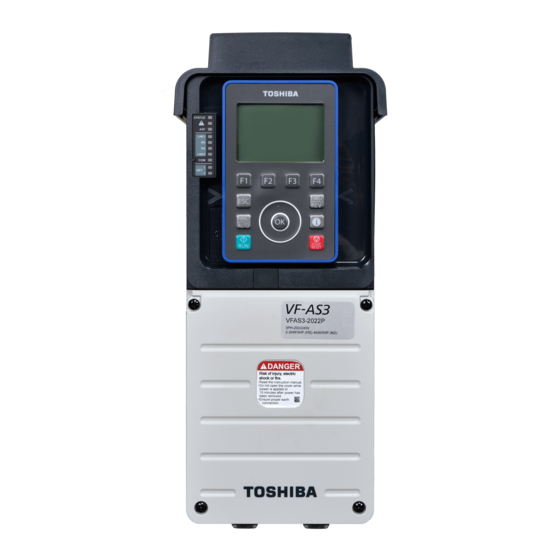
Read first This chapter explains check items when you receive the inverter, names of parts of the inverter, and the flow of basic procedures before operation. 1. 1 Check product purchase CAUTION • Use the inverter that conforms to specifications of the power supply and the three-phase motor to be operated. - Page 20 Name plate Name plate Inverter type Type indication label Inverter rated output capacity Rated voltage Danger label Rated input current Rated output current Manufactured in Indonesia from foreign and domestic components TOSHIBA INDUSTRIAL PRODUCTS AND SYSTEMS CORPORATION 1. Read first...
- Page 21 E6582062 Danger label kit Quick start Danger labels in 6 languages for sticking . • French • German • Italian • Spanish CD-ROM • Chinese Instruction manual is included as electronic data. • Japanese DC reactor Only for frame size A7 and A8. •...
-
Page 22: Multi-Rating
E6582062 1. 2 Multi-rating This inverter has multi-rating. Select rating with the parameter <AUL: Multi-rating select> according to the characteristics of the load to be applied. <AUL>="2: ND rating (120%-60s) (0 after execution)" - Select it to apply equipment with variable torque characteristic. - Example) Fans, pumps, blowers, etc. -
Page 23: Indication Of Product Type
E6582062 1. 3 Indication of product type Explanation of the indication of the inverter type. VFAS3 - 4 004 P C E Model name Input voltage Applicable motor capacity of HD (for ND) Additional function II E: IP55 type TOSVERT 2: 200 V - 240 V 004: 0.4 kW (0.75 kW) VF-AS3 series... - Page 24 E6582062 Type-Form Frame size 240V 480V VFAS3-2450P, 2550P VFAS3-4900PC to 4132KPC VFAS3-4160KPC VFAS3-4200KPC to 4280KPC 1. Read first...
-
Page 25: Structure Of Equipment
E6582062 1. 4 Structure of equipment The following is brief explanation of the names and functions of parts that compose the inverter. 1. 4. 1 Outside view This inverter has eight types of units with frame size A1 to A8 (made of resin or metal) according to the voltage class and the capacity. - Page 26 E6582062 • Top cover A cover to protect the top of the inverter, which is attached to models with frame size A1 to A5. Remove this cover to install inverters side by side or in a location with ambient temperature above 50°C for heat discharge.
-
Page 27: Operation Panel
E6582062 1. 4. 2 Operation panel and peripherals The operation panel of the inverter is directly connected to RS485 communication connector 1. It is equipped with some indicators for inverter status on the left side of the operation panel. Indicator for inverter status LCD screen Operation keys Operation panel lower... -
Page 28: Led Indicators
E6582062 • Operation panel female connector For handy use, connect the operation panel to this female connector with a cable. To mount the operation panel on the cabinet, use the Door mounting kit SBP010Z (optional). • USB-miniB connector Used only by manufacturer. •... -
Page 29: Terminal Blocks
E6582062 1. 4. 3 Terminal blocks This inverter is equipped with a power terminal block and a control terminal block. To the power terminal block, connect the power supply and the motor. To the control terminal block, connect external control signals. - Page 30 E6582062 ■ Control terminal block The control terminal block is common to all the types and is located on the lower side of the operation panel. It connects wiring between the inverter and an external control device. Control terminal block is detachable. Ethernet connector 1 Ethernet connector 2 Control terminal...
- Page 31 E6582062 • Connection of Ethernet to the RS485 communication connectors may result in a malfunction. Important 1. 4. 4 Features of inverter This inverter has the following features. A detachable LCD operation panel is equipped as standard • A touch wheel is adopted for excellent environment resistance. •...
-
Page 32: Operation Procedure
E6582062 1. 5 Operation procedure The basic procedure to operate a motor with the inverter is as follows. Reference Check of packed items -> [1.1 Check product purchase] Check of installation site -> [2.1.1 Installation environment] Carrying-in to installation site ->... - Page 33 E6582062 Switching of grounding capacitor -> [2.3.4 Switching of grounding capacitor] (If necessary) Mounting of front cover -> [2.2 How to remove covers of inverter] Connection of peripheral devices (when not wired in the inverter) -> [2.4.1 Motor], [2.4.2 Inverters], [2.4.3 What to do about Check of safety measures leakage current] Power ON...
-
Page 35: Installation And Wiring
Installation and wiring WARNING • Never disassemble, modify or repair. This can result in electric shock, fire and other injury. Please call your Toshiba distributor for repairs. Disassembly prohibited • Do not stick your fingers into openings such as cable wiring holes and cooling fan covers. -
Page 36: Installation
E6582062 2. 1 Installation Take special care with the installation environment of the inverter. Install the inverter in a location that secures space for ventilation and heat emitting (in the cabinet, etc.), considering heat generation and occurrence of noise. 2. 1. 1 Installation environment WARNING •... - Page 37 • If the inverter is installed in a location that is subject to vibration, anti-vibration measures are required. Please consult with your Toshiba distributor about these measures. If the inverter is installed near any of the equipment listed below, provide mea- sures to insure against errors in opera- tion.
- Page 38 WARNING • Do not install and operate the inverter if it is damaged or any of its components is missing. This will result in electric shock or fire. Please call your Toshiba distributor for repairs. Prohibited • Mount the inverter on a metal plate.
- Page 39 E6582062 H 3 or more H 1 or more 11 cm 11 cm H 3 or more or more or more H 2 or more Type H1(cm) H2(cm) H3(cm) VFAS3-2004P - 2370P VFAS3-4004PC - 4750PC VFAS3-2450P, 2550P VFAS3-4900PC - 4132KPC VFAS3-4160KPC VFAS3-4200KPC - 4280KPC 1) Basic installation...
- Page 40 E6582062 ■ Current reduction curve The current value of the inverter that can be output continuously varies depending on the installation method, ambient temperature, and the setting of carrier frequency. For details, refer to "Instruction manual for load reduction" (E6582116). ■...
- Page 41 E6582062 The amount of forcible air-cooling ventilation required and the necessary heat discharge surface quantity when operating in a sealed cabinet depending on motor capacity are as follows. <ND rating> Forced Sealeded air-cooled cabinet Applicable Input Inverter Inner side Required Necessary motor Frame...
- Page 42 E6582062 Forced Sealeded air-cooled cabinet Applicable Input Inverter Inner side Required Necessary motor Frame voltage Inverter type-form calorific value calorific value ventilation heat discharge capacity size Class (W) *1 (W) *1 amount surface (kW) /min) quantity (m 0.75 4004PC 0.32 1.13 4007PC 0.45...
- Page 43 E6582062 ■ When more than one inverter are installed in one cabinet When two or more inverters are installed in one cabinet, pay attention to the followings. • Ensure a space of at least 20 cm or more on the top and bottom of the inverters. (Note: Depending on the inverter type.) •...
-
Page 44: How To Remove Covers Of Inverter
E6582062 2. 2 How to remove covers of inverter WARNING • Never remove the front cover when the power is on. The unit contains high voltage parts and contact with them will result in electric shock. Prohibited CAUTION • When removing and mounting the front cover, wiring cover or the power terminal block with a screwdriver, be sure not to scratch your hand as these results in injury. - Page 45 E6582062 2. 2. 1 With frame size A1, A2, or A3 VFAS3-2004P to 2075P, VFAS3-4004PC to 4185PC The parts to be removed are as follows. Top cover • Front cover on the lower side of the front surface (resin) • Top cover on the top surface (resin) Each cover can be removed separately.
- Page 46 E6582062 ■ Top cover Put your fingers in the clearance in the back from the upper Top cover side of the top cover, and pull the cover toward you while lift- ing it upward. The tab shown in the figure on the right comes off. •...
- Page 47 E6582062 ■ Front cover Loosen four screws of the front cover. Since the screws are of falling prevention type, they do not come off the front cover even if loosened. Remove the front cover from the unit. Front cover The upper part of the front cover has no inserted part. Mount the front cover in the reverse procedure.
- Page 48 E6582062 2. 2. 3 With frame size A5 Top cover VFAS3-2220P to 2370P, VFAS3- 4450PC to 4750PC The parts to be removed are as follows. • Front cover in the middle of the front surface (metal) • Wiring cover on the lower side of the front surface (metal) •...
- Page 49 E6582062 ■ Top cover Remove two screws of the top cover. Top cover Store the removed screws so as not to be lost. Screw Pull the top cover slightly toward you. The tab shown in the figure on the right comes off. Lift the top cover upward and remove it from the unit.
- Page 50 E6582062 ■ Front cover Remove six screws of the front cover. Store the removed screws so as not to be lost. Front cover Screw Lift the bottom end of the front cover, pull the entire cover downward and remove it from the unit. Since the upper part of the front cover has an inserted part, the cover cannot be removed just by lifting it.
- Page 51 E6582062 Remove two screws of the wiring duct. Store the removed screws so as not to be lost. Remove one nut. Screw Store the removed nut so as not to be lost. Wiring duct Lift the left side of the wiring duct first and remove it from the unit.
- Page 52 E6582062 ■ Front cover (lower) Remove four screws of the front cover (lower). Store the removed screws so as not to be lost. Lift the front cover (lower) and remove it from the unit. The upper side of the front cover (lower) has three tabs.
- Page 53 E6582062 ■ Wiring duct and Duct cover Remove the front cover (lower) and the transparent cover. Refer to the procedure above. Remove two screws of Duct cover. Store Duct cover and screws so as not to be lost. Screw Wiring duct and Duct cover Remove two nuts of the wiring duct.
- Page 54 E6582062 Remove the wiring duct from the unit by pulling it down. Wiring duct and Duct cover Mount Wiring duct and Duct cover in the reverse pro- cedure. First, insert the upper right part of the wiring duct to the unit.
- Page 55 E6582062 ■ Front cover (upper) Remove the front cover (lower) and the DC reactor cover. Refer to the procedure above. Remove eight screws of the front cover (upper). Store the removed screws so as not to be lost. Front cover (upper) Screw Lift the lower end of the front cover (upper) slightly,...
- Page 56 E6582062 Loosen four screws of the front cover. Since the screws are of falling prevention type, they do not come off the front cover even if loosened. Front cover Hold the both side of the front cover and pull it slightly downward.
- Page 57 E6582062 Frame size A2 VFAS3-2037P, VFAS3-4055PC, 4075PC Charge lamp Frame size A3 VFAS3-2055P, 2075P, VFAS3-4110PC to 4185PC Charge lamp Frame size A4 VFAS3-2110P to 2185P, VFAS3-4220PC to 4370PC Charge lamp Frame size A5 VFAS3-2220P to 2370P, VFAS3-4450PC to 4750PC Charge lamp 2-23 2.
- Page 58 E6582062 ■ With frame size A6 to A8 VFAS3-2450P, 2550P, VFAS3-4900PC to 4280KPC You can check the charge lamp without opening the cover.When removing the front cover, be sure to check that the charge lamp is off. Charge lamp Charge lamp Charge lamp Frame size A6 Frame size A7...
-
Page 59: Wiring
2. 3 Wiring WARNING • Never disassemble, modify or repair. This can result in electric shock, fire and other injury. Please call your Toshiba distributor for repairs. Disassembly prohibited • Do not stick your fingers into openings such as cable wiring holes and cooling fan covers. - Page 60 E6582062 • The grounding wire must be connected securely. If the grounding wire is not securely connected, when the inverter has failure or earth leakage, this will result in electric shock or fire. grounded CAUTION • Do not attach devices with built-in capacitors (such as noise reduction filters or surge absorbers) to the output terminals (motor side).
- Page 61 E6582062 2. 3. 2 Standard connection method WARNING • Do not connect power supply to the output (motor side) terminals [U/T1], [V/T2] and [W/T3]. Connecting power supply to the output will damage the inverter and result in fire. • Do not insert a braking resistor between DC terminals [PA/+] and [PC/-] or [PO] and[PC/-]. This will result in fire.
- Page 62 E6582062 For details of the peripheral devices, refer to [Chapter 10]. • An noise filter is built in all the types as standard. • A DC reactor is built in as standard or attached (frame size A7, A8). Braking resistor •...
- Page 63 E6582062 Pass the motor wiring through the cable clamp. The cable clamp exists only in frame size A1 to A5. Mount the motor wiring to the screw of each corresponding terminal. Mount ferrules with insulation sleeve terminal and crimp-style terminal with insulation sleeve to the end of each wire of the motor in advance.
- Page 64 E6582062 Tighten two screws of the cable clamp and fix the motor wiring (four wires) with the cable clamp. The cable clamp exists only in frame size A1 to A5. Cable Screws (x2) Clamp Tighten the two screws of the clamp to fix the cable Similarly, mount the power supply wiring to the terminals [R/L1], [S/L2], and [T/L3] and a terminal [PE] after passing it through other cable clamp.
-
Page 65: Standard Connection Diagram
E6582062 • For the layout and shape of power terminal block of each frame size, refer to [2. 3. 3]. • The cable clamp exists only in frame size A1 to A5. Memo • Covers to be removed at the time of wiring vary depending on the frame size. For details, refer to [2. - Page 66 E6582062 [Standard connection diagram - Sink] This diagram shows an example of a standard connection for 240 V class, 0.4 to 37kW and 480 V class, 0.4 to 75kW (frame size A1 to A5). Power supply 240 V class: +DC -DC 0.4 - 37 kW Three-phase 200 - 240 V-50/60 Hz 480 V class:...
- Page 67 E6582062 [Standard connection diagram - Sink] This diagram shows an example of a standard connection for 240 V class, 45 - 55 kW and 480 V class, 90 - 132 kW (frame size A6). Power supply 240 V class: 45 - 55 kW Three-phase 200 - 240 V-50/60 Hz +DC -DC 480 V class:...
- Page 68 E6582062 [Standard connection diagram - Sink] This diagram shows an example of a standard connection for 480 V class, 160 kW (frame size A7). Power supply 480 V class: +DC -DC 160 kW Three-phase 380 - 440 V-50 Hz Three-phase 380 - 480 V-60 Hz PA/+ PC/- MCCB...
- Page 69 E6582062 [Standard connection diagram - Sink] This diagram shows an example of a standard connection for 480 V class, 200 to 280 kW (frame size A8). Power supply Braking unit Braking resistor 480 V class: +DC -DC 200 - 280 kW Three-phase 380 - 440 V-50 Hz Three-phase 380 - 480 V-60 Hz PA/+ PC/- BU+ BU-...
- Page 70 E6582062 [Standard connection diagram - Source] This diagram shows an example of a standard connection for 240 V class, 0.4 to 37 kW and 480 V class, 0.4 to 75 kW (frame size A1 to A5). Power supply 240 V class: +DC -DC 0.4 - 37 kW Three-phase 200 - 240 V-50/60 Hz...
- Page 71 E6582062 [Standard connection diagram - Source] This diagram shows an example of a standard connection for 240 V class, 45 to 55 kW and 480 V class, 90 to 132 kW (frame size A6). Power supply 240 V class: 45 - 55 kW Three-phase 200 - 240 V-50/60 Hz +DC -DC 480 V class:...
- Page 72 E6582062 [Standard connection diagram - Source] This diagram shows an example of a standard connection for 480 V class, 160 kW (frame size A7). Power supply 480 V class: +DC -DC 160 kW Three-phase 380 - 440 V-50 Hz Three-phase 380 - 480 V-60 Hz PA/+ PC/- MCCB...
- Page 73 E6582062 [Standard connection diagram - Source] This diagram shows an example of a standard connection for 480 V class, 200 to 280 kW (frame size A8). Power supply Braking unit Braking resistor 480 V class: +DC -DC 200 - 280 kW Three-phase 380 - 440 V-50 Hz Three-phase 380 - 480 V-60 Hz PA/+ PC/- BU+ BU-...
-
Page 74: Symbol
E6582062 2. 3. 3 Power terminals The power terminals are connected to the power supply (primary side) and the motor (secondary side). ■ Functions of power terminals Terminal Applicable Function symbol frame size Grounding terminal for inverter case. There are 3 terminals in cooling fin All frame sizes or mounting part of EMC plate. - Page 75 E6582062 ■ Recommended tightening torque of power terminal screws Power terminal torque and wire strip length Torque Strip length Screw size Frame size Cable size (mm) (N・m) (lb・in) 11.5 13.3 44.3 AWG2 or smaller 88.5 AWG1 or bigger 88.5 AWG1/0 or smaller AWG2/0 or bigger A7/A8 A7/A8...
- Page 76 E6582062 ■ Arrangement of power terminals 1) Frame size A1 VFAS3-2004P to 2022P, VFAS3-4004PC to 4037PC Charge lamp M4 screw Grounding terminal (M5 screw) CAUTION • Following type of screwdriver should be used for M4 screw; Mandatory PH2 (phillips, bit type2), shaft diameter 5.0 mm or less. action 2) Frame size A2 VFAS3-2037P,VFAS3-4055PC, 4075PC...
- Page 77 E6582062 3) Frame size A3 VFAS3-2055P, 2075P, VFAS3-4110PC to 4185PC Charge lamp M5 screw Grounding terminal (M5 screw) 4) Frame size A4 VFAS3-2110P to 2185P, VFAS3-4220PC to 4370PC Charge lamp M8 screw Grounding terminal (M8 screw) Grounding terminal (M6 screw) 5) Frame size A5 VFAS3-2220P to 2370P, VFAS3-4450PC to 4750PC Charge lamp...
- Page 78 E6582062 6) Frame size A6 VFAS3-2450P, 2550P, VFAS3-4900PC to 4132KPC Input/output Grounding terminal (M8 screw) Grounding terminal (M10 screw) 7) Frame size A7 VFAS3-4160KPC M12 screw Fan terminal Fan terminal M4 screw Ground capacitor switching screw M12 screw M10 screw Grounding terminal (M12 screw) 2-44 2.
- Page 79 E6582062 8) Frame size A8 VFAS3-4200KPC to 4280KPC M12 screw Fan terminal Fan terminal M4 screw Ground capacitor switching screw M12 screw Grounding terminal (M12 screw) 2. 3. 4 Switching of grounding capacitor WARNING • When using this 480V class inverter with a power supply system that is grounded in other than the neutral point (e.g.
- Page 80 E6582062 ■ With frame size A1 VFAS3-2004P to 2022P, VFAS3-4004PC to 4037PC Remove the front cover. Grounding For how to remove, refer to [2. 2. 1]. Screw Remove two screws for switching of grounding capacitor. Screw The grounding capacitor is disconnected. Mount the removed screws to the positions shown in the figure on the right and tighten them.
- Page 81 E6582062 ■ With frame size A2 VFAS3-2037P, VFAS3-4055PC, 4075PC Remove the front cover. Grounding For how to remove, refer to [2. 2. 1]. Remove two screws for switching of grounding capacitor. The grounding capacitor is disconnected. Insert the removed screws to the positions shown in the figure on the right.
- Page 82 E6582062 ■ With frame size A3 VFAS3-2055P, 2075P, VFAS3-4110PC to 4185PC Remove the front cover. Grounding For how to remove, refer to [2. 2. 1]. Screw Remove two screws for switching of grounding capacitor. Screw The grounding capacitor is disconnected. Insert the removed screws to the positions shown in the figure on the right.
- Page 83 E6582062 ■ With frame size A4 VFAS3-2110P to 2185P, VFAS3-4220PC to 4370PC Remove the front cover. Grounding mark For how to remove, refer to [2. 2. 2]. Nongrounding mark Grounding Remove the screw(s) for switching of grounding capacitor from the position of the grounding mark and insert it/them into the position of the non-grounding mark.
- Page 84 E6582062 ■ With frame size A5 VFAS3-2220P to 2370P, VFAS3-4450PC to 4750PC Remove the front cover. Grounding For how to remove, refer to [2. 2. 3]. Screw Remove the screw for switching of grounding capacitor from the position of the grounding mark and tighten it to the posi- tion of the non-grounding mark.
- Page 85 E6582062 ■ With frame size A7 VFAS3-4160KPC Remove the front cover and the transparent cover inside (transparent resin). For how to remove, refer to [2. 2. 5]. Remove the screw for switching of grounding capacitor from the position of the grounding mark and tighten it to the position of the grounding mark.
- Page 86 E6582062 ■ With frame size A8 VFAS3-4200KPC to 4280KPC Remove the front cover and the transparent cover inside (transparent resin). For how to remove, refer to [2. 2. 5]. Remove the screw for switching of grounding capacitor from the position of the grounding mark and tighten it to the position of the grounding mark.
-
Page 87: Control Terminals
E6582062 2. 3. 5 Control terminals The control terminals are connected to external control equipment to control operation of the inverter and motor and monitor the state externally. ■ Functions of control terminals The control terminal block is common to all the models. 2-53 2. - Page 88 E6582062 Terminal Input/ Electrical Function Internal circuit symbol output specifications Multifunction programmable digital input. In the default setting, Input forward run is performed with ON and deceleration stop with OFF. Multifunction programmable Digital input. digital input. In the default setting, Input •...
- Page 89 E6582062 Terminal Input/ Electrical Function Internal circuit symbol output specifications Common An equipotential terminal of the to input/ control circuit. It is allocated in output three positions. +24V 10 Vdc Voltage Voltage reference output for Output (allowable load potentiometer. Regulator current: 10 mAdc) +24V Digital output...
- Page 90 E6582062 Terminal Input/ Electrical Function Internal circuit symbol output specifications Multifunction programmable analog output. 0 - 10 Vdc output with default setting. With <F681: 0 - 10 Vdc Output Terminal FM switching>, meter (allowable load option (0 - 1 mA), current (0 - 20 resistance: 1 kΩ...
- Page 91 E6582062 Terminal Input/ Electrical Function Internal circuit symbol output specifications Multifunction programmable relay Maximum contact contact output. Operation of the capacity protection function of the inverter • 250 Vac-2 A +24V Output is detected in the default setting. (cosφ=1) The contact across [FLA]-[FLC] is •...
- Page 92 E6582062 Wire size Using two wires Using one wire Using two wires with twin ferule Conductor Solid wire 0.14-2.5 26-14 2x0.14 to 2x0.75 26-18 Relay Stranded wire 0.14-2.5 26-14 2x0.14 to 2x0.75 26-18 2x0.5 to 2x1.5 20-16 Solid wire 0.14-2.5 26-14 2x0.14 to 2x1.0 26-18...
- Page 93 E6582062 Sink logic Source logic SINK SINK SOURCE SOURCE 24Vdc 24Vdc Input Input Common Output Output Common 24Vdc Output Programmable Inverter Common P24 controller Input Programmable Inverter controller 2) When an external power supply is used The terminal [PLC] is used to connect to an external power supply or to separate a terminal from other input or output terminals.
- Page 94 E6582062 2. 3. 6 RS485 communication connectors This inverter is equipped with two RS485 communication ports. To use RS485, refer to "RS485 Communication Function Instruction Manual" (E6582143). • Connection of Ethernet to the RS485 communication connectors will result in a failure. Important 2.
- Page 95 E6582062 2. 3. 8 Mounting of DC reactor Caution • Mount the attached DC reactor (DCL) for VFAS3-4160KPC ~ 4280KPC. If you do not mount the attached DC reactor (DCL), it will result in malfunction. Mount the DC reactor (DCL) between [PA/+] and [PO]. Mandatory action This inverter is equipped with a DC reactor (DCL) as standard, however, for VFAS3-4160KPC to...
- Page 96 E6582062 Remove four screws of the top cover (mesh) of the DC Top cover Screw reactor. Store the removed screws so as not to be lost. Remove the top cover (mesh) from the DC reactor. Check the positions of four mounting holes on the back side of the DC reactor and mount the DC reactor to the panel.
- Page 97 E6582062 Mount the DC reactor cover to the DC reactor and tighten DC reactor cover four screws according to necessity of other work. After mounting the DC reactor to the inverter, mount the front cover (upper) before the DC reactor cover. Screw •...
-
Page 98: Cautions For Application
E6582062 2. 4 Cautions for application This section introduces cautions for use of the motor and inverter, influence of leakage current on periph- eral devices, and measures against it. 2. 4. 1 Motor CAUTION • Use the inverter that conforms to specifications of the power supply and the three-phase motor to be operated. - Page 99 E6582062 ■ Occurrence of instability (abnormal vibrations and overcurrent trips) Unstable phenomena such as abnormal vibrations and overcurrent trips may occur depending on combinations of the inverter and motor, and load. 1) In the following cases, lower the settings of inverter carrier frequency. •...
- Page 100 E6582062 Circuit diagram 1 is an example in which the standby function is assigned to the terminal [S2]. This circuit can be applied to a machine that mainly operates horizontally. Set the terminal [S2] to "Open" to turn off output of the inverter and have the motor in coasting state. Then. operate the brake. If the brake is operated with inverter output, the inverter may trip due to bound current.
- Page 101 E6582062 ■ Operating at other than rated voltage Connections to voltages other than the rated voltage described in the rating label cannot be made. If a connection must be made to a power supply other than one with rated voltage, use a transformer to raise or lower the voltage to the rated voltage.
- Page 102 E6582062 2. 4. 3 What to do about leakage current CAUTION • Take countermeasures against leakage current. The leakage current through the stray capacitance of the input/output power wires of inverter and motor can affect peripheral devices. In that case, please take countermeasures such as reducing the carrier frequency or shortening the length of input/output power wires.
- Page 103 E6582062 ■ Influence of leakage current across lines (in case of thermal relays) The high frequency component of current leaking into electrostatic capacity between inverter output wires will increase the effective current values and make externally connected thermal relays operate unnecessarily.
- Page 104 E6582062 ■ Influence of leakage current across lines (in case of CT and ammeter) If a CT and ammeter are connected externally to detect inverter output current, the leak current's high frequency component may destroy the ammeter. If the wires are long (50 m or more) or in case of models with motors of low rated current (several A (ampere) or less), especially the 480 V class low capacity (4.0 kW or less, 5.5 kW or less with ND) models, it will be easy for the high frequency component to pass through the externally connected CT and be superimposed on and burn the...
-
Page 105: Basic Operation] Operation Panel And Screen Display
[Basic operation] Operation panel and screen display This chapter introduces the functions of the operation keys on the operation panel and screen display and explains how to operate them. • The specifications and operation procedure of the operation panel are common to all the types Memo of this inverter. - Page 106 E6582062 • [ESC] key This key switches the display mode. It is also used to return to the previous item of the hierarchy of the screen. • [HAND/AUTO] key This key switches between hand (operation panel)/remote (remote control). It is used to operate the inverter temporarily at hand (operation panel) while performing terminal operation (remote control) normally.
- Page 107 E6582062 ■ Website (QR code) STOP 0.0Hz When you press the [i] key, information is displayed. 17:17 Website top For example, you can access easily from your smartphone Scan the QR code to to our website by displaying the QR code. access the detailed information ESC = Return...
- Page 108 E6582062 ■ Parameter information You can see QR code for the parameter when the parameter is selected or edited. STOP 0.0Hz 10:01 Basic parameters : Lower limit frequency 0.0Hz ACC : Acceleration time 1 10.0s dEC : Deceleration time 1 10.0s : Preset speed 0 0.0Hz...
- Page 109 E6582062 ■ [F1] - [F4] keys The [F1] - [F4] keys are used to execute the items (text, symbol, icon, etc.) displayed on the lower side of the LCD screen. STOP 0.0Hz 17:12 Standard Mode Screen Copy Setting Monitor Press [F1] key to execute Press [F2] key to execute Press [F3] key to execute Press [F4] key to execute...
-
Page 110: Display Mode
E6582062 Screen display Function Reference Displayed Display position Inverts the backlight color (white or red) [3. 1. 3] [3. 1. 3] Move setting to right [4. 2. 1] Page down (If there are more than six choices) Middle [F3] right R (Back) Searches backward [4. - Page 111 E6582062 [Monitor mode] • You can check the status such as the operation status of the inverter and terminal information. The following are the top screen of each mode and how to switch between them. When switching with the [F1] - [F4] keys STOP 0.0Hz 17:12...
- Page 112 E6582062 When switching with the [ESC] key STOP 0.0Hz 17:12 Standard Mode Screen Copy Setting Monitor [Standard mode] STOP 0.0Hz STOP 0.0Hz 17:13 17:13 Monitor Mode Setting Mode Direction of rotation 1. History function Forward Output frequency 2. Direct access 0.0Hz Output current 3. Guidance function Input voltage(DC detection) 4. Basic parameters...
-
Page 113: The Symbol
E6582062 ■ Screen display of [Standard mode] This is the normal display mode of the inverter. (1) - (6) are display contents common to [Standard mode], [Setting mode], [Easy mode], and [Monitor mode]. 20.0Hz 17:18 Standard Mode 20.0 Screen Copy Setting Monitor (10) - Page 114 E6582062 Run command from Icon Run / Stop RS485 communication Stop (connector 2) Communication option Stop The remaining capacity of the battery ( yes/ no) is displayed with icons. The current time ("hour/minute") is displayed. Current display mode [Standard mode] is displayed. Normally, the output frequency (default setting) is displayed.
- Page 115 E6582062 The functions assigned to the [F1] - [F4] keys are displayed. For details, refer to [3. 1. 1]. ■ Screen display of [Easy mode] This is a display mode to set parameters easily. It is displayed in the following cases. •...
- Page 116 E6582062 Furthermore, if is displayed in the [F4] key when selecting an item with the touch wheel, detailed information is displayed when you press the [OK] key. The functions assigned to the [F1] - [F4] keys are displayed. For details, refer to [3. 1. 1]. Memo •...
-
Page 117: Language Selection
E6582062 ■ Language selection STOP 0.0Hz Select a language to be displayed from the list. 17:15 Language select You can select among English, German, Italian, Spanish, English Portuguese, Chinese (simplified). (French and Russian Deutsch are in preparation.) Italiano The default setting is English. Español 中文... -
Page 118: Copy Function
E6582062 ■ Switching of backlight color STOP 0.0Hz 17:14 When you press the [F3] key ( mark), you can LCD screen setting change the color of the backlight to white or red. Language select The color is switched every time you press the key. Data/Time setting 2016/06/01 Screen contrast... - Page 119 E6582062 Copying to LCD (uploading) Select "Copy to the keypad" and press the [OK] or STOP 0.0Hz [F2] key. 15:20 Copy function Copy to the drive Copy to the keypad Return Set a figure 0 - 99 after the inverter type followed STOP 0.0Hz by #, and press the [OK] or [F2] key.
- Page 120 E6582062 Copying to inverter (downloading) Select "Copy to the drive", and press the [OK] or STOP 0.0Hz [F2] key. 15:37 Copy function Copy to the drive Copy to the keypad Return Select a file to be downloaded to the inverter and STOP 0.0Hz press the [OK] or [F2] key.
-
Page 121: Normal/Emergency Screen Display
E6582062 3. 2 Normal/emergency screen display This section explains the screen display of the operation panel. When operation such as parameter setting is not performed, the top screen of [Standard mode] is displayed. During run, output frequency, etc. are displayed, and the status of alarm and trip is displayed when an error occurs. - Page 122 E6582062 Even if [Standard mode] is switched to other display mode, 20.0Hz you can grasp the operation status from the display in the 17:18 Monitor Mode status area. Direction of rotation Forward Output frequency 20.0Hz Output current Input voltage (DC detection) 116% Output voltage Easy...
- Page 123 E6582062 3. 2. 3 Emergency off To apply emergency off from the operation panel except when the inverter is operated by the operation panel, follow the procedure below. For how to apply emergency off by other than the operation panel (digital input, etc.), refer to [6. 30. 4]. Press the [STOP/RESET] key.
- Page 124 E6582062 3. 2. 4 How to reset trip If a trip occurs, you can reset it with panel operation. For how to reset a trip by other than the operation panel (digital input, etc.), refer to [13. 1]. Press the [STOP/RESET] key with the trip displayed. Trip 20.0Hz "CLr"...
-
Page 125: Basic Operation] Operation Methods Of Motor
[Basic operation] Operation methods of motor WARNING • Do not touch terminals when the inverter's power is on even if the motor is stopped. Touching the terminals while voltage is applied will result in electric shock. • Do not touch switches when the hands are wet and do not try to clean the inverter with a damp cloth. -
Page 126: To Run/Stop Motor
E6582062 • Use the inverter that conforms to specifications of the power supply and the three-phase motor to be operated. If you use the inappropriate inverter, not only will the three-phase motor not rotate correctly, but it will cause serious accidents such as overheating and burning out. •... -
Page 127: Basic Setting Methods Of Parameters
E6582062 Memo • For how to switch other operation method to panel run, refer to [4. 3], [5. 2. 1]. ■ Terminal run The motor is operated with an external signal. Run/stop the motor with an ON/OFF signal to a digital input terminal. Also, input the frequency command with potentiometer/voltage/current signals to analog input terminals. - Page 128 E6582062 STOP 0.0Hz STOP 0.0Hz 14:00 14:45 Setting Mode Easy Mode 1. History function : Run command select CMOd 2. Direct access : Frequency command select 1 FMOd 3. Guidance function : Acceleration time 1 10.0s 4. Basic parameters : Deceleration time 1 10.0s 5. Extended parameters(F - - -) : Upper limit frequency 60.0Hz...
- Page 129 E6582062 Select a parameter you want to change and press the [OK] key. STOP 0.0Hz 14:00 In the example on the right, <F101: Reach signal History function specified frequency> is selected. : Icon areadisplay of operation paneh F723 : Reach signal frequency F101 2.5Hz : Panel Fwd/Rev run...
- Page 130 E6582062 • The following parameters are not displayed in the history function. <FC: Panel run frequency> <AUF: Guidance function> <AUA: Application easy setting> <AUL: Multi-rating select> <AU1: Automatic Acc/Dec> <AU2: Torque boost macro> Memo <SEt: Region setting check> <tyP: Default setting> <F699: Trip for test>...
- Page 131 E6582062 Set the value with the touch wheel. The first, second, and third digits from the right are STOP 0.0Hz 14:03 changed between "0" to "9." The fourth digit from Direct access the right is changed among "0", "A", and "C." Set the communication number The values are carried or borrowed.
- Page 132 E6582062 How to use For example, set preset speed operation in the following procedure. Select Guidance function "2: Preset speed operation" and press the [OK] key. STOP 0.0Hz 14:33 Guidance function Embedded Ethernet Preset speed guidance Analog signal operation guidance Motor 1,2 switching guidance Motor parameter guidance Monitor...
- Page 133 E6582062 List of parameters changeable by guidance function Embedded Ethernet setting Motor 1,2 switching <AUF>=1 <AUF>=4 C081-C096 Device name 1-16 Base frequency 1 C610 Emb Eth. IP setting mode Base frequency voltage 1 C611-C614 Emb Eth. IP address setting value Manual torque boost 1 C615-C618 Emb Eth.
- Page 134 E6582062 4) Basic parameter Basic parameters for inverter operation are STOP 0.0Hz 14:36 displayed. Basic parameters For details, refer to [5. 3], [5. 4], [11. 2]. : Application easy setting : Eco-standby power setting : Multi-rating select : Automatic Acc/Dec : Toque boost macro 5) Extended parameter (F---) Extended parameters used for complicated...
- Page 135 E6582062 • Since all the parameters are compared with the default setting values, it may take a few Memo seconds until parameters are displayed. • To cancel parameter search, press the [ESC] key. Read the changed parameter in the following procedure. Select "8.
- Page 136 E6582062 When you press the [F4] key ("F(Next)") repeat- edly, the changed parameters are displayed one by STOP 0.0Hz 14:43 one. Changed parameters search & edit F618 Overtoque detection time 1.0s Return R(Back) F(Next) When you press the [F3] key ("R(Back)"), the changed parameters are displayed one by one STOP 0.0Hz...
- Page 137 E6582062 The setting screen of the parameter is opened. STOP 0.0Hz 14:43 F618 :Overtoque detection time Min: 0.0 Max: 10.0 X1000 X100 Change the setting of the selected parameter and press the [OK] key. STOP 0.0Hz 14:43 F618 :Overtoque detection time Min: 0.0 Max: 10.0 X1000...
- Page 138 E6582062 ■ [Easy mode] In [Easy mode], basic ten (default setting) parameters are displayed. Up to 32 parameters can be registered to be displayed. STOP 0.0Hz STOP 0.0Hz 14:45 14:46 Easy Mode Easy Mode : Run command select : Lower limit frequency CMOd 0.0Hz : Frequency command select 1...
- Page 139 E6582062 <F701: Current, voltage units select> Select the unit of current/voltage displayed on the operation panel among % or A (ampere)/V (volt). For details, refer to [5. 2. 7]. <PSEL: Parameter mode select> Select the parameter mode between [Setting mode] and [Easy mode]. For details, refer to [5.
- Page 140 E6582062 ■ Setting of parameter for which an item should be selected For an example, here is a procedure to set an extended parameter <F710: Standard mode display>. Press the [ESC] key to change from [Standard mode] to [Setting mode]. STOP 0.0Hz 14:47...
- Page 141 E6582062 Select "3.7. Panel parameter (F7--)" with the touch wheel. STOP 0.0Hz 15:09 Extended parameters (F ---) Operation parameters (F3 - -) Motor parameters 1 (F4 - -) Acc/dec parameters (F5 - -) Protection parameters (F6 - -) Panel parameters (F7 - -) Monitor Press the [OK] key.
- Page 142 E6582062 Select a new setting value. Select it by using the touch wheel, the [F2] key STOP 0.0Hz 15:08 F710 : Standard mode display and the [F3] key 0: Output frequency In the example on the right, the setting value is 1: Frequency reference changed to "2: Output current."...
- Page 143 E6582062 ■ With parameters for which a value should be set For an example, here is a procedure to set the basic parameter <ACC: Acceleration time 1>. At that time, the current setting value, unit, setting lower limit (Min:), and setting upper limit (Max:) are displayed.
-
Page 144: Basic Panel Run Methods
E6582062 4. 3 Basic panel run methods This section introduces panel run methods with basic examples. Input a run command and a frequency command from the operation panel. 4. 3. 1 [Operation example 1] Operating with [RUN] key/ [STOP] key on operation panel Operate only with the operation panel. - Page 145 E6582062 The setting screen is displayed. STOP 0.0Hz 15:14 CMOd :Run command select 0: Terminal 1: Operation panel,Ext panel 2: Embedded Ethernet 3: RS485 com (connector 1) 4: RS485 com (connector 2) Select "1: Operation panel, Extension panel" and press the [OK] key. STOP 0.0Hz 15:15...
- Page 146 E6582062 Select "10: Touch wheel 1 (power off or press OK to save)" and press the [OK] key. STOP 0.0Hz 15:16 FMOd :Frequency command select 1 6: - 7: - 8: - 9: - 10: Touch wheel 1 (power off or press The basic parameter screen is displayed.
- Page 147 E6582062 Press the [OK] key. The screen returns to the [Standard mode] screen. STOP 0.0Hz 14:47 Standard Mode Easy Screen Copy Monitor 10 When you press the [RUN] key, the motor starts running. 30.0Hz 15:30 In the main area of the [Standard mode] screen, Standard Mode 30.0 the output frequency is displayed.
- Page 148 E6582062 • How to switch the display mode of the operation panel -> Refer to [3. 1. 2] Reference • Procedure to change parameter setting -> Refer to [4. 2. 3] • Details of <Fr: Panel Fwd/Rev run select> -> Refer to [5. 3. 9] Operate the motor with the operation panel according to [4.
- Page 149 E6582062 The basic parameter screen is displayed. Check that the setting value of <Fr: Panel Fwd/Rev 30.0Hz 15:33 run select> is "2." Basic parameters : Panel Fwd/Rev run : tHrA tHrA 4.00A : Motor OL characteristic : FM function FMSL : FM 100.0% •...
- Page 150 E6582062 • Icon of direction of rotation When you press the [FWD/REV] key again, the direction of rotation of the motor is switched to forward run. The motor decelerates and shows 0.0 Hz once. Then, it accelerates to the value set with <FC: Panel run frequency>...
-
Page 151: Basic Terminal Run Methods
E6582062 4. 4 Basic terminal run methods WARNING • Do not touch terminals when the inverter's power is on even if the motor is stopped. Touching the terminals while voltage is applied will result in electric shock. • Do not touch switches when the hands are wet and do not try to clean the inverter with a damp cloth. - Page 152 E6582062 PA/+ PC/- MCCB Motor ELCB R/L1 U/T1 S/L2 V/T2 T/L3 W/T3 Fwd run Operation panel Common Turn off the power of the inverter. Remove the covers of the control terminal block and parts required for connection. Covers to be removed vary depending on the type of the inverter. For details of how to remove the covers, refer to [2.
- Page 153 E6582062 Switch to [Setting mode]. Select "4. Basic parameter" and press the [OK] STOP 0.0Hz 15:13 key. The basic parameter screen is displayed. Setting Mode 1. History function 2. Direct access 3. Guidance function 4. Basic parameters 5. Extended parameters(F - - -) Monitor Select <CMOd: Run command select> and press the [OK] key.
- Page 154 E6582062 11 Select "10: Touch wheel 1 (power off or press OK to save)" and press the [OK] key. STOP 0.0Hz 15:17 The basic parameter screen is displayed. Basic parameters Check that the setting value of <FMOd: Frequency : Run command select CMOd command select 1>...
- Page 155 E6582062 16 When you turn on the external switch, the motor starts running. 30.0Hz 15:30 In the main area of the [Standard mode] screen, Standard Mode 30.0 the output frequency is displayed. The motor accelerates according to the setting of <ACC: Acceleration time 1>, and its frequency changes to the frequency command value set with <FC: Panel run frequency>...
- Page 156 E6582062 • How to switch the display mode of the operation panel -> Refer to [3. 1. 2] • Procedure to change parameter setting -> Refer to [4. 2. 3] • Details of <CMOd: Run command select>, and <FMOd: Frequency command select 1> -> Reference Refer to [5.
- Page 157 E6582062 Check that the slide switch [SW1] is on the SINK side. SINK If it is set to PLC/SOURCE side, set it to the SINK side. SOURCE For details of the slide switch, refer to [2. 3. 5]. Check connection of the terminals to be used on the control terminal block.
- Page 158 E6582062 Select <CMOd: Run command select> and press the [OK] key. STOP 0.0Hz 15:51 You can also select <CMOd: Run command Basic parameters select> on the [Easy mode] screen. : Run command select CMOd : Frequency command select 1 FMOd : V/f Pattern : Manual torque boost 1 4.80%...
- Page 159 E6582062 The basic parameter screen is displayed. Check that the setting value of <FMOd: Frequency STOP 0.0Hz 15:55 command select 1> is "1." Basic parameters In this setting, the voltage signal input to the : Run command select CMOd terminal [RR] should be the frequency command. : Frequency command select 1 FMOd Here, the voltage input to the terminal [RR] is...
- Page 160 E6582062 16 In [Setting mode], change the setting value of <FMOd: Frequency command select 1> to "2: STOP 0.0Hz 15:56 Terminal RX." FMOd :Frequency command select 1 In this setting, set the frequency command with the 1: Terminal RR voltage signal (0 - 10 Vdc or -10 to +10 Vdc) 2: Terminal RX connected to the terminal [RX].
- Page 161 E6582062 19 When you turn off the external switch, the motor decelerates and stops. • You can also change the input specification of the terminal [RR] to PTC input, etc. Memo For details, refer to [6. 2. 3]. 4-37 4. [Basic operation] Operation methods of motor...
- Page 162 E6582062 4. 4. 3 [Operation example 3] Switching run/stop and frequency with external switch Digital input both a run command and a frequency command externally. • First, check connection from external contacts such as switch/relays to the control terminal. Here is a case where run/stop is input by a switch and a frequency command is operated by 3-speed operation (controlled with two relays).
- Page 163 E6582062 Check that the slide switch [SW1] is on the SINK side. SINK If it is set to PLC/SOURCE side, set it to the SINK side. SOURCE For details of the slide switch, refer to [2. 3. 5]. Check connection of the terminals to be used on the control terminal block.
- Page 164 E6582062 Select <CMOd: Run command select> and press the [OK] key. STOP 0.0Hz 15:51 Basic parameters : Run command select CMOd : Frequency command select 1 FMOd : V/f Pattern : Manual torque boost 1 4.80% : Base frequency 1 60.0Hz The setting screen is displayed.
- Page 165 E6582062 13 Press the [OK] key. The screen returns to the basic parameter screen. 14 Similarly, select <Sr2: Preset speed 2> and <Sr3: Preset speed 3> and change the setting values. STOP 0.0Hz 15:59 Basic parameters : Deceleration time 1 10.0s : Preset speed 0 0.0Hz...
- Page 166 E6582062 The output frequency changes to the frequency command value set with <Sr1: Preset speed 1> 20.0Hz 20:51 and becomes stable. Standard Mode 20.0 In the example on the right, it is 20.0 Hz. Easy Screen Copy Monitor The following are always displayed in the status Output frequency area on the upper side of the screen regardless of <Sr1>...
-
Page 167: Fundamental Operation] How To Use Parameters
[Fundamental operation] How to use parameters Frequently set parameters include default 10 parameters in [Easy mode] and basic parameters. This chapter describes these parameters. 5. 1 Table of parameter access 5. 2 Settings of main parameters This section describes how to select run and frequency commands required for operating the motor, how to limit the output frequency, how to set acceleration/deceleration time, how to set the electronic thermal for motor protection, and how to adjust the meter. - Page 168 E6582062 ■ Selecting a setting value 0: Terminal Run/stop the inverter with an external ON/OFF signal. For how to set terminals and parameters to be used, refer to [4. 4]. For details of operation by external signals, refer to [Chapter 7]. 1: Operation panel, Extension panel Press the [RUN], [STOP] key on the operation panel to run/stop the inverter.
- Page 169 E6582062 Selecting how to input a frequency command <FMOd: Frequency command select 1> STOP 0.0Hz 15:06 FMOd :Frequency command select 1 Basic parameter Easy mode 1: Terminal RR 2: Terminal RX 3: Terminal Ⅱ 4: Terminal AI4(option) 5: Terminal AI5(option) ■...
- Page 170 E6582062 For details of operation by external signals, refer to "Chapter 7". 4: Terminal AI4 (option) The terminal [AI4] is included in the cassette option. Input a frequency command with an analog signal. For details of the optional terminal [AI4], refer to [10. 4. 1]. 5: Terminal AI5 (option) The terminal [AI5] is included in the cassette option.
- Page 171 E6582062 21: RS485 communication (connector 1) Remove the operation panel, connect a communication cable, and input a frequency command through the RS485 communication. For details, refer to [6. 38]. 22: RS485 communication (connector 2) Connect a communication cable to the RS485 communication connector 2 next to the control termi- nal block, and input a frequency command through the RS485 communication.
- Page 172 E6582062 Example of switching run and frequency commands The figure below shows an example of switching run and frequency commands. CMOd: Extension panel (option) Run command Input terminal For use of RKP007Z select function: Input terminal 108/109 function: (Terminal run 48/49 priority) (Communication...
- Page 173 E6582062 5. 2. 2 Setting rated frequency and rated voltage of motor <vL: Base frequency 1> STOP 0.0Hz 15:25 :Base frequency 1 Basic parameter 60.0 Min: 15.0 Max: 590.0 X1000 X100 <vLv: Base frequency voltage 1> STOP 0.0Hz 15:26 :Base frequency voltage 1 Basic parameter Min: 50 Max: 660...
- Page 174 E6582062 • You can set four types of motor rating. For details including <F170: Base frequency 2>, refer to Memo [6. 4]. 5. [Fundamental operation] How to use parameters...
- Page 175 E6582062 5. 2. 3 Setting the output frequency limit Setting the maximum frequency of the inverter <FH: Maximum frequency> STOP 0.0Hz 15:08 :Maximum frequency Basic parameter 80.0 Min: 30.0 Max: 590.0 X1000 X100 ■ Function Set the maximum value of the frequency output from the inverter. This frequency is also the criteria of acceleration and deceleration time.
- Page 176 E6582062 Setting the upper and lower limits of the output frequency <UL: Upper limit frequency> STOP 0.0Hz 15:08 :Upper limit frequency Basic parameter Easy mode 60.0 <LL: Lower limit frequency> Min: 0.0 Max: 80.0 Basic parameter Easy mode X1000 X100 STOP 0.0Hz 15:08...
- Page 177 E6582062 Upper limit frequency Lower limit frequency Output frequency (Hz) Output frequency (Hz) <FH> <FH> <UL> <LL> Frequency command Frequency command signal (%) signal (%) 100% 100% • Frequencies under the setting value of <F240: Start frequency> are not output. --> Refer to [6. 7.
- Page 178 E6582062 5. 2. 4 Setting acceleration/deceleration time <ACC: Acceleration time 1> STOP 0.0Hz 15:09 :Acceleration time 1 Basic parameter Easy mode 10.0 <dEC: Deceleration time 1> Min: 0.0 Max: 6000.0 Basic parameter Easy mode X1000 X100 STOP 0.0Hz 15:10 :Deceleration time 1 10.0 Min: 0.0 Max: 6000.0...
- Page 179 E6582062 ■ Guideline for the setting The criteria of acceleration time and deceleration time is the value of <FH: Maximum frequency>. Note that it is not the value of <UL: Upper limit frequency>. You can use <F519: Unit of Acc/Dec time> to switch the unit of setting time between 0.1s and 0.01s. With acceleration/deceleration time set to 0.0 second, the unit of 0.05 second is used internally for <F519>...
- Page 180 E6582062 5. 2. 5 Protecting the motor from overload <tHrA: Motor overload protection current 1> STOP 0.0Hz 15:10 tHrA :Motor overload protection current 1 Basic parameter Easy mode 4.00 Min: 0.40 Max: 4.00 X1000 X100 ■ Function Set a protection characteristic of the electronic thermal suited for the rating and characteristic of the motor.
- Page 181 E6582062 What is overload stall? • The overload stall function can apply to variable torque characteristic load where a lower frequency reduces load current, such as a fan, pump, and blower. When the inverter detects overload, this function automatically lowers the output frequency Memo before the motor overload trip "OL2"...
- Page 182 E6582062 ■ Setting a time before the trip of the electronic thermal occurs: <F607: Motor overload time> Setting a time before the trip of the electronic thermal occurs: <F607: Motor overload time> Set a time before the overload trip "OL2" occurs at the motor overload of 150%. Default Title Parameter name...
- Page 183 E6582062 Title Parameter name Adjustment range Default setting F631 Inverter overload detection 0: 150%-60s 1: Temperature estimation 0: 120%-60s 1: Temperature estimation Set <F631: Inverter overload detection> to "1: Temperature estimation". • If the inverter overload trip "OL1" occurs, you can clear it by decreasing the value of <F601: Stall prevention level 1>...
- Page 184 E6582062 • The overload detection level depends on the output frequency or carrier frequency. ■ Saving an overload integral value at power off : <F632: Electronic thermal memory target> Set a target to reset the integral value of overload at power off. It applies to both the motor electronic thermal and overload detection for inverter protection.
- Page 185 E6582062 5. 2. 6 Adjusting the meter connected to the inverter <FM: Terminal FM adjustment> STOP 0.0Hz 15:11 :Terminal FM adjustment Basic parameter Easy mode 0.0Hz Output frequency <FMSL: Terminal FM function> 100.0% Min: 0.1 Max: 250.0 Basic parameter X1000 X100 <F671: Terminal AM adjustment>...
- Page 186 E6582062 Default Title Parameter name Adjustment range setting 10: Output frequency during run. Frequency command value during stop. 11: Torque current 12: Exciting current 13: PID feedback value 14: Motor overload factor (OL2 data) 15: Inverter overload factor (OL1 data) 16: Braking resistor overload factor (OLr data) 17: Braking resistor load factor (%ED) 18: Input power...
- Page 187 E6582062 Default Title Parameter name Adjustment range setting 130: External PID3 set value 131: External PID3 feedback value 132: External PID3 result value 133: External PID4 set value 134: External PID4 feedback value 135: External PID4 result value 136 - 149: - 150: Signed output frequency 151: Signed frequency command value 152: Signed stator frequency...
- Page 188 E6582062 In the basic parameters of [Setting mode], set <FMSL: Terminal FM function> to "0: Output 60.0Hz 15:12 frequency". Basic parameters The default setting of <FMSL> is "0". : Terminal FM function FMSL : Terminal FM adjustment 100.0% : Default setting : Region setting check FMSL : Parameter mode select...
- Page 189 E6582062 • 18, 19 : 200% of rated power • 20, 21 : 1000 x F749 • 24, 25, 26, 28, 29, 31, 41, 44, 45, 74, 75, 76, 160, 161, 162 : Maximum value • 27, 71 : FH x 60/F856 •...
- Page 190 E6582062 ■ Function Select the display units of parameters and monitors represented in current and voltage. ■ Parameter setting Default Title Parameter name Adjustment range setting F701 Current, voltage units 0: % select 1: A (ampere), V (volt) ■ Applicable parameters and monitors The following list shows parameters and monitors whose display units can be changed with <F701: Current, voltage units select>.
- Page 191 E6582062 ■ Setting example While a model with a rated current of ●● A is used at the rated load (100% load), the monitor mode is displayed as follows: 60.0Hz 60.0Hz 15:15 15:15 Monitor Mode Monitor Mode Direction of rotation Direction of rotation Forward Forward...
- Page 192 E6582062 5. 2. 8 Selecting the parameter mode between [Setting mode] and [Easy mode] <PSEL: Parameter mode select> STOP 0.0Hz 15:16 PSEL :Parameter mode select Basic parameter Easy mode 0: Setting mode at power on 1: Easy mode at power on 2: Easy mode only ■...
- Page 193 E6582062 ■ Setting parameters in [Easy mode] Up to 32 parameters are displayed in [Easy mode]. Set among <F751: Easy setting 1> through <F782: Easy setting 32>. Title Parameter name Adjustment range Default setting F751 Easy setting 1 0 - 2999 3<CMOd>...
- Page 194 E6582062 5. 2. 9 Returning parameters to their default settings Clearing each history <tyP: Default setting> STOP 0.0Hz 15:19 Typ : Default setting Basic parameter 0: - 1: 50Hz setting 2: 60Hz setting 3: Default setting 1 4: Clear past trips ■...
- Page 195 E6582062 ■ Selecting a setting value 1: 50Hz setting The following parameters are set for the base frequency 50 Hz. Setting values of other parameters are not changed. When you select a parameter and press the [OK] key, nothing appears momentarily, the same content displayed at power on appears, and the mode enters [Standard mode].
- Page 196 E6582062 2: 60Hz setting The following parameters are set for the base frequency 60Hz. Setting values of other parameters are not changed. When you select a parameter and press the [OK] key, nothing appears momentarily, the same content displayed at power on appears, and the mode enters [Standard mode]. <FH: Maximum frequency>...
- Page 197 E6582062 3: Default setting 1 Return parameters except for some ones to their default settings. When you select the setting and press the [OK] key, "Init" blinks in the main area and "Initializing" appears under it for a while. They disappear momentarily, the same content displayed at power on appears, and the mode enters [Standard mode].
- Page 198 When you select the setting and press the [OK] key, nothing appears momentarily, the same content displayed at power on appears, and the mode enters [Standard mode]. 6: Initialize typeform Clear a trip if the type error "EtyP" occurs. However, if it occurs, contact your Toshiba distributor. 5-32 5. [Fundamental operation] How to use parameters...
- Page 199 E6582062 When you select the setting and press the [OK] key, nothing appears momentarily, the same content displayed at power on appears, and the mode enters [Standard mode]. 7: Store user settings Store the setting values of all current parameters. 8: Rewrite user settings Rewrite the setting values of the parameters stored in "7: Store user settings"...
-
Page 200: Setting Other Basic Parameters
E6582062 5. 3 Setting other basic parameters This section describes basic parameters not included in [5.2]. Set any parameter in the [Setting mode]. 5. 3. 1 Setting energy savings <AUE: Eco-standby power setting> STOP 0.0Hz 15:22 AUE : Eco-standby power setting Basic parameter 0: - 1: Embedded Ethernet OFF... - Page 201 E6582062 5. 3. 2 Selecting an overload protection characteristic <AUL: Multi-rating select> STOP 0.0Hz 15:22 AUL : Multi-rating select Basic parameter 0: - 1: - 2: ND rating (120%-60s)(0 after set) 3: HD rating (150%-60s)(0 after set) 4: - ■ Function Select an inverter overload protection characteristic suited for the torque characteristic of the machine.
- Page 202 E6582062 5. 3. 3 Acceleration/deceleration time adjustment automatically according to load <AU1: Automatic Acc/Dec> STOP 0.0Hz 15:23 AU1 : Automatic Acc/Dec Basic parameter 0: Disabled 1: Automatic Acc/Dec 2: Automatic Acc only ■ Function This is a parameter that automatically adjusts the acceleration/deceleration time according to the load condition to prevent an overcurrent trip during acceleration/deceleration.
- Page 203 E6582062 • Use this parameter with the motor connected. • When the inverter is used with a load that fluctuates considerably, it may fail to adjust the acceleration or deceleration time in time, and therefore may be tripped. • When using the optional braking resistor or braking unit, do not set <AU1: Automatic Acc/Dec> Important to "1".
- Page 204 E6582062 5. 3. 4 Selecting motor control method <Pt: V/f Pattern> STOP 0.0Hz 15:24 Pt : V/f Pattern Basic parameter 0: V/f constant 1: Variable torque 2: Automatic torque boost 3: Vector control 1 4: Energy savings ■ Function This is a parameter to select the motor control method according to the characteristics and application of the machinery.
- Page 205 E6582062 Output voltage (V) <vLv: Base frequency voltage 1> <vb> (%) Output frequency (Hz) <vL: Base frequency 1> To increase the torque at low speeds, increase the setting value of <vb: Manual torque boost 1>. For details, refer to [5. 3. 6]. 1: Variable torque This is applied to loads such as fans, pumps and blowers in which the torque is proportional to the square of load motor speed.
- Page 206 E6582062 When the motor you are using is a 4P Toshiba premium efficiency motor which has the same capac- ity as the inverter, there is basically no need to set the parameters. First, look at the motor name plate and set the following parameters.
- Page 207 When <Pt> is "4", setting of motor parameters is required. When the motor you are using is a 4P Toshiba premium efficiency motor which has the same capac- ity as the inverter, there is basically no need to set the parameters.
- Page 208 E6582062 • <F405: Motor rated capacity> • <F415: Motor rated current> • <F417: Motor rated speed> Two parameter setting methods are provided. 1) Setting with <F400: Offline auto-tuning> Set <F400: Offline auto-tuning> to "5". For details, refer to [6. 23. 1]. * If an auto-tuning error occurs, set motor parameters individually by referring to [6.
- Page 209 When <Pt> is "9", setting of motor parameters is required. When the motor you are using is a 4P Toshiba premium efficiency motor which has the same capac- ity as the inverter, there is basically no need to set the parameters.
- Page 210 E6582062 10: PG feedback control Vector control is performed by using speed feedback signals from the motor. Attach the PG feedback option to the inverter. Use a motor with speed sensor (encoder) and connect signals from the encoder to the PG feedback option. In the following cases, use <Pt>...
- Page 211 E6582062 ■ Cautions for automatic torque boost and vector control • Look at the motor name plate and be sure to set the following parameters. - <vL: Base frequency 1> (Rated frequency) - <vLv: Base frequency voltage 1> (Rated voltage) - <F405: Motor rated capacity>...
- Page 212 E6582062 • If the inclination of the set V/f is over 8.25%/Hz, the alarm "A-02" will appear. When "A-02" alarm occurs, internal V/f is limited to 8.25%/Hz. 5-46 5. [Fundamental operation] How to use parameters...
- Page 213 E6582062 5. 3. 5 Setting parameters for torque boost and energy saving easily <AU2: Torque boost macro> STOP 0.0Hz 15:24 AU2 : Torque boost macro Basic parameter 0: Disabled 1: Auto torque boost + auto-tuning 2: Vector control 1 + auto-tuning 3: Energy savings + auto-tuning ■...
- Page 214 E6582062 2: Vector control 1 + offline auto- tuning This is applied to load transporting machinery and elevators that require high torque and machine tools that require high precision. High-torque and high-precision stable operation is realized in the speed range from startup to base frequency.
-
Page 215: Increasing Starting Torque
E6582062 5. 3. 6 Increasing starting torque <vb: Manual torque boost 1> STOP 0.0Hz 15:25 :Manual torque boost 1 Basic parameter 4.80 Min: 0.00 Max: 30.00 X1000 X100 ■ Function The starting torque is increased by increasing the setting value when starting torque is required. It is valid when the setting value of <Pt: V/f Pattern>... - Page 216 E6582062 5. 3. 7 Operating by switching frequency command with external logic signal <Sr0: Preset speed 0> to <Sr7: Preset speed 7> STOP 0.0Hz 15:26 :Preset speed 1 Basic parameter <F287: Preset speed 8> to <F294: Preset speed 15> <F964: Preset speed 16> to <F979: Preset speed 31> Min: 0.0 Max: 60.0 X1000...
- Page 217 E6582062 ■ Setting example of preset speed frequency Here is a case of sink logic (when the slide switch [SW1] is set to SINK). Preset speed operation Termi- [S1] [S2] ...
- Page 218 E6582062 Output frequency (Hz) <Sr1> <Sr3> <Sr2> Time Terminal [F] Terminal [S1] (Preset speed switching 1) Terminal [S2] (Preset speed switching 2) ■ When changing frequency command during run The frequency command can be changed during run with preset speed command. Set <F724: Frequency setting target by touch wheel>...
- Page 219 E6582062 Title Parameter name Adjustment range Default setting F560 Preset speed operation 0: Frequency only style 1: With function 0: Frequency only Only the frequency command is valid. 1: With function For each preset speed commands of 1-speed to 15-speed, direction of rotation, acceleration/ deceleration time, V/f control, and torque limit can be set.
- Page 220 E6582062 5. 3. 8 Setting PID control <FPld: PID1 set value> STOP 0.0Hz 15:27 FPld :PlD1 set value Basic parameter Min: 0.0 Max: 60.0 X1000 X100 ■ Function This parameter is applied to process control including keeping airflow, pressure, and the amount of flow constant.
- Page 221 E6582062 Default Title Parameter name Adjustment range setting F389 PID1 set value select 0: selected by FMOd/F207 1: Terminal RR 2: Terminal RX 3: Terminal II 4: Terminal AI4 (option) 5: Terminal AI5 (option) 6 - 11: - 12: FPId 13, 14: - 15: Terminal Up/Down frequency 16: Pulse train...
- Page 222 E6582062 • PID control can be temporarily turned off with an external signal. Assign "36: PID control OFF" to an input terminal. Memo • PID control should be OFF when very low speed drive is needed. • If speed PID is selected, motor is possibly rotating forward and reverse. If you don't want to rotate reverse, set <F311: Reverse inhibited>...
- Page 223 E6582062 Output frequency <F363> Small PID set value Residual deviation <F363> Large Time The integral/derivative amount of PID control can be reset with an external signal. Assign function number "52: PID differential/integral reset" to an input terminal. <F366: PID1 differential gain> This parameter adjusts the differential gain level of PID control.
- Page 224 E6582062 Example of 0 - 10 Vdc voltage input setting Example of -10 - +10 Vdc voltage input setting Output frequency (Hz) Output frequency (Hz) <F204> <F213> (60Hz) (60Hz) <F202> <F211> (0Hz) (0Hz) Terminal [RR] input value Terminal [RX] input value <F201>...
- Page 225 E6582062 5. 3. 9 Switching direction of rotation during panel run <Fr: Panel Fwd/Rev run select> STOP 0.0Hz 15:28 Fr : Panel Fwd/Rev run Basic parameter 0: Fwd run 1: Rev run 2: Fwd run(switch F/R by panel) 3: Rev run(switch F/R by panel) ■...
- Page 226 E6582062 • display of the rotation direction icon. • Direction of rotation of the rotating icon • "Forward"/"Reverse" display of the direction of rotation in [Monitor mode]. When the [FWD]/[REV] key is valid, is displayed at the upper right of the LCD screen. When the motor is running forward, is highlighted.
- Page 227 E6582062 5. 3. 10 Automatic setting of main parameters by region used WARNING • Make sure to set the setup menu correctly. If you set the setup menu incorrectly, this will damage the inverter or cause the inverter to perform unexpected movement. Mandatory action <SEt: Region setting check>...
- Page 228 E6582062 STOP 0.0Hz STOP 0.0Hz 15:30 15:33 Setup Standard mode 1: Japan 2: Mainly North America 3: Mainly Asia 4: Mainly Europe 5: Mainly China Setting for Japan Easy Screen Copy Monitor • While the setup menu is started, you cannot return to the previous step even if you press the [ESC] key.
- Page 229 E6582062 Mainly Mainly Mainly Parameter title Function North China Japan Asia Europe America Frequency (max of set F606, F643 60.0 50.0 50.0 50.0 60.0 value) (Hz) Motor rated F405 Capacity (kW) 0.37 F704 Reference Website Depending on the region and the capacity. Refer to [11. 6]. •...
-
Page 230: Setting Of Extended Parameters That Are Especially Important
E6582062 5. 4 Setting of extended parameters that are especially important This section explains the parameters that are especially important among the extended parameters. For other extended parameters not introduced here, refer to "Chapter 6". 5. 4. 1 Switching two frequency commands <FMOd: Frequency command select 1>... - Page 231 E6582062 ■ Parameter setting Default Title Parameter name Adjustment range setting FMOd Frequency command 0: - select 1 1: Terminal RR 2: Terminal RX F207 Frequency command 3: Terminal II select 2 4: Terminal AI4 (option) 5: Terminal AI5 (option) 6 - 9: - 10: Touch wheel 1 (power off or press OK to save)
- Page 232 E6582062 ■ Switching with input terminal <F200> = "0" Set <F200: Frequency command priority select> to "0". Assign "104: FMOd/F207 priority switching" to an unused input terminal. For details, refer to [7. 2. 1]. • When the input terminal is OFF, run the motor with the frequency command set with <FMOd: Frequency command select 1>.
- Page 233 E6582062 5. 4. 2 Restarting smoothly after momentary power failure CAUTION • When the auto-restart after momentary stop function is selected, stand clear of motors and machines at momentary power failure. The motors and machines which have stopped due to momentary power failure will restart suddenly after power is restored, and this will result in injury.
- Page 234 E6582062 Output frequency Motor speed Terminal [F] or [R] (Run command) 2: Terminal ST On/Off The motor speed and direction of rotation of the coasting motor are detected to start it smoothly (motor speed search function). The input terminal to which "ST: Standby" is assigned is turned off. It is operated when the input terminal is turned on again.
- Page 235 E6582062 • At restart, it takes about 1 second for the inverter to check the motor speed. For this reason, the startup takes more time than usual. • Use this function when operating a system with one motor connected to one inverter. This function may not operate properly in a system configuration when multiple motors are connected to one inverter.
- Page 236 E6582062 5. 4. 3 Customizing display Selecting contents displayed in [Standard mode] <F710: Standard mode display> <F720: Standard mode display of extension STOP 0.0Hz 15:36 panel> F710 : Standard mode display 0: Output frequency 1: frequency reference 2: Output current 3: DC Bus voltage 4: Output voltage ■...
- Page 237 E6582062 ■ Setting list of <F710: Standard mode display> and <F720: Standard mode display of extension panel> Set- Set- Display ting Function name Display unit ting Function name unit value value Motor speed (estimated Output frequency 0.1 Hz value) Communication option Frequency command value 0.1 Hz Receiving counter...
- Page 238 E6582062 Set- Set- Display ting Function name Display unit ting Function name unit value value Pump 4 run time 100 hours 10000 Number of starting times 10000 Terminal RR input value Number of Fwd starting times 10000 Terminal RX input value Number of Rev starting times Terminal II input value...
- Page 239 E6582062 Set- Set- Display ting Function name Display unit ting Function name unit value value Signed speed feedback PID set value 0.1 Hz 0.1Hz frequency (1-second filter) Light-load high-speed Signed torque switching load torque Light-load high-speed torque Signed torque command during constant speed run Pattern operation group Signed torque current...
- Page 240 E6582062 Displaying frequency by converting to other unit <F702: Free unit multiplication factor> <F703: Target of free unit> STOP 0.0Hz 15:37 <F705: Free unit inclination polarity> F702 :Free unit multiplying factor 0.00 <F706: Free unit bias> Min: 0.00 Max: 200.00 X1000 X100 ■...
- Page 241 E6582062 <A220>, <A222>, <A226>, <A227>, <A229>, <A230>, <A316>, <A317>, <A319>, <A320>, <A322>, <A323>, <A326>, <A327>, <A923> - <A927> <C154>, <C155>, <C697> When <F703: Target of free unit> is "1" It applies only to the PID control-related frequency. • PID control-related parameters: <FPId>, <F364>, <F365>, <F367>, <F368>, <F374>, <A316>, <A317>, <A319>, <A320>, <A326>, <A327>...
- Page 242 E6582062 Positive inclination Positive inclination with bias <F705>="1 ", <F706>="0.00" <F705>="1", <F706>="20.00" Panel display Panel display 1000 <F702> <F702> Output frequency (Hz) Output frequency (Hz) 80 (Hz) 80 (Hz) Negative inclination <F705>="0", <F706>="80.00" Panel display <F702> Output frequency (Hz) 80 (Hz) •...
-
Page 243: Advanced] How To Use Parameters
[Advanced] How to use parameters This inverter has basic parameters and other three types of parameters such as extended parameters (with F), advanced parameters, (with A), and communication parameters (with C). These parameters are used for sophisticated operations, detailed settings, special purposes, etc. This chapter explains how to use the parameters that are not mentioned in the previous chapters. - Page 244 E6582062 Output frequency (Hz) Frequency command value <F100: Low-speed signal output frequency> Time (s) [R1A]-[R1C] output (Low-speed signal) ■ Output terminal parameter setting Low-speed signal is the default setting for terminal [R1]. Title Parameter name Adjustment range Default setting F133 Terminal R1 function 1 0-255 For details on the output terminal functions, refer to [7.
- Page 245 E6582062 6. 1. 2 Output a signal when reached to a frequency command (output the Acc/Dec completed signal) <F102: Reach signal detection band> STOP 0.0Hz 12:43 F102 : Reach signal detect band Min: 0.0 Max: 80.0 X1000 X100 ■ Function When the output frequency becomes the frequency command ±<F102: Reach signal detection band>, the Acc/Dec completed signal is output from the output terminal.
- Page 246 E6582062 • When you want to output the inversion signal (OFF signal), set "7". • The signals can be also output from the other output terminals depending on the parameter setting. When you want to output the signals from the [FLA]-[FLB]-[FLC] relay logic output terminals, Memo set at <F132: Terminal FL function>.
- Page 247 E6582062 6. 1. 3 Output a signal when reached to a specified frequency (output the specified frequency attainment signal) <F101: Reach signal specified frequency> <F102: Reach signal detection band> STOP 0.0Hz 12:45 F101 : Reach signal frequency Min: 0.0 Max: 80.0 X1000 X100 ■...
- Page 248 E6582062 • When you want to output the inversion signal (OFF signal), set "9". Memo • When a run command (Fwd signal or Rev signal) is OFF, the specified frequency attainment signal is also OFF. • How to operate the operation panel -> Refer to [3. 1. 1. •...
-
Page 249: Input Signals To The Control Terminals
E6582062 6. 2 Input signals to the control terminals Various signals are input to the inverter for motor operation. For details on the input terminal function, refer to [7. 2. 1]. 6. 2. 1 Selecting operation at simultaneous input of Fwd/ Rev commands <F105: Fwd/Rev priority of both close>... - Page 250 E6582062 1: Stop When the Fwd and Rev signals are simultaneously input, deceleration stop is performed. Output frequency (Hz) Frequency command value Time (s) Terminal [F] (Fwd run) Terminal [R] (Rev run) • How to operate the operation panel -> Refer to [3. 1. 1]. •...
- Page 251 E6582062 6. 2. 2 Selecting input voltage of the terminal [RX] <F107: Terminal RX input voltage select> STOP 0.0Hz 12:45 F107 : Terminal RX input voltage select 0: 0 to +10V 1: -10 ∼ +10V ■ Function This parameter selects the input voltage of the terminal [RX]. ■...
- Page 252 E6582062 6. 2. 3 Selecting input signal of the terminal [RR] <F108: Terminal RR input select> STOP 0.0Hz 12:46 F108 : Terminal RR input select 1: Voltage input (0-10V) 2: - 3: - 4: PTC input 5: PT100(2-wire)input ■ Function This parameter selects the input signal of the terminal [RR].
- Page 253 E6582062 6. 2. 4 Selecting input signals of the optional terminals [AI4] and [AI5] <F148: Terminal AI4 input select> <F149: Terminal AI5 input select> STOP 0.0Hz 12:46 F148 : AI4 input select 1: Voltage input (0-10V) 2: Voltage input (-10 to +10V) 3: Current input (0-20mA) 4: PTC input 5: PT100(2-wire)input...
-
Page 254: Selecting Terminal Functions
E6582062 6. 3 Selecting terminal functions 6. 3. 1 Always enabling the input terminal functions (always ON) <F110: Always active function 1> <F127: Always active function 2> STOP 0.0Hz 12:47 <F128: Always active function 3> F110 : Always active function 1 6: Standby 6(Invers) 8: Reset 1... - Page 255 E6582062 • Coast stop is a stop pattern where the inverter output is turned OFF, and the motor rotation stops spontaneously. The deceleration stop is performed by default setting (the frequency is decreased to 0 Hz by the inverter deceleration time). •...
- Page 256 E6582062 6. 3. 2 Changing the input terminal functions <F111: Terminal F function 1> <F112: Terminal R function 1> <F113: Terminal RES function 1> <F114: Terminal S1 function 1> <F115: Terminal S2 function> <F116: Terminal S3 function> <F117: Terminal S4 function> <F118: Terminal S5 function>...
- Page 257 E6582062 6. 3. 3 Changing the output terminal functions <F130: Terminal FP function 1> <F132: Terminal FL function > <F133: Terminal R1 function 1> <F134: Terminal R2 function > <F135: Terminal R1 delay time> <F136: Terminal R2 delay time> <F137: Terminal FP function 2> <F138: Terminal R1 function 2>...
-
Page 258: Switching Two To Four Types Of Motor Characteristics
E6582062 6. 4 Switching two to four types of motor characteristics <F170: Base frequency 2> <F171: Base frequency voltage 2> STOP 0.0Hz 12:49 <F172: Manual torque boost 2> F170 : Base frequency 2 60.0 <F174: Base frequency 3> <F175: Base frequency voltage 3> <F176: Manual torque boost 3>... - Page 259 E6582062 Title Parameter name Adjustment range Unit Default setting F176 Manual torque boost 3 0.00-30.00 F178 Base frequency 4 15.0 - 590.0 50.0/60.0 F179 Base frequency voltage 4 240V class: 50-330V 480V class: 50-660V F180 Manual torque boost 4 0.00-30.00 F182 Motor overload protection Depending on capacity...
- Page 260 E6582062 Output terminal Input terminal (function number) Parameters selected S1-CC S2-CC No.186 No.188 Base frequency 3: <F174> Base frequency voltage 3: <F175> Manual torque boost 3: <F176> Motor overload protection current 3: <F183> Base frequency 4: <F178> Base frequency voltage 4: <F179> Manual torque boost 4: <F180>...
-
Page 261: V/F 5-Point Setting
E6582062 6. 5 V/f 5-point setting <F190: V/f 5-point VF1 frequency> <F191: V/f 5-point VF1 voltage> <F192: V/f 5-point VF2 frequency> <F193: V/f 5-point VF2 voltage> <F194: V/f 5-point VF3 frequency> <F195: V/f 5-point VF3 voltage> <F196: V/f 5-point VF4 frequency> <F197: V/f 5-point VF4 voltage>... -
Page 262: Setting The Frequency Commands
E6582062 6. 6 Setting the frequency commands You can set the frequency commands in various methods. Select a frequency command setting method according to operation. You can also switch the frequency commands using signals to the terminals. 6. 6. 1 Switching two types of frequency commands <F200: Frequency command priority select>... - Page 263 E6582062 <F229: AI5 point 1 frequency> <F230: AI5 point 2 input value> <F231: AI5 point 2 frequency> <F810: Communication frequency point select> <F811: Communication point 1 input value> <F812: Communication point 1 frequency> <F813: Communication point 2 input value> <F814: Communication point 2 frequency> ■...
- Page 264 E6582062 Title Parameter name Adjustment range Unit Default setting F210 RX point 1 input value -100 to +100 F211 RX point 1 frequency 0.0-590.0 F212 RX point 2 input value -100 to +100 F213 RX point 2 frequency 0.0-590.0 50.0/60.0 F214 RX point 1 rate -250 to +250...
- Page 265 E6582062 ■ Setting method Set a frequency command for an analog input amount at two points. For the corresponding parameters of each terminal and the setting method, refer to the following. As default setting, the range between the minimum and maximum input amounts is set to 0 to 50.0/ 60.0 Hz for main analog signal of the terminals.
- Page 266 E6582062 3) For setting voltage input of -10 to +10 V (terminal [RX]), refer to the following figure. Output frequency (Hz) <F213> 50/60(Hz) -100% (-10V) <F210> 0(Hz) Voltage signal (%) <F212> 100% (+10V) <F211> <F107: Terminal RX input voltage select> = "-10 to +10 V" •...
- Page 267 E6582062 The allowance is zero setting on default setting. ■ Parameter setting Title Parameter name Adjustment range Unit Default setting F470 RR input bias 0-255 F471 RR input gain 0-255 F472 RX input bias 0-255 F473 RX input gain 0-255 F474 II input bias 0-255...
- Page 268 E6582062 When you want to output the set maximum frequency at the maximum voltage and current values, decrease the gain value for a corresponding terminal. However, if the set value is too small, the maximum frequency may not be output even when voltage and current reach the maximum values.
- Page 269 E6582062 6. 6. 4 Input the frequency commands by pulse trains <F146: Terminal S4 input select> <F147: Terminal S5 input select> STOP 0.0Hz 12:58 <F234: Pulse train input point 1 input value> F146 : S4 input select <F235: Pulse train input point 1 frequency> 0: Digital input <F236: Pulse train input point 2 input value>...
- Page 270 E6582062 ■ Guideline for the setting When you want to use the terminal [S4], set <F146: Terminal S4 input select> to "1: Pulse train input". When you want to use the terminal [S5], set <F147: Terminal S5 input select> to "1: Pulse train input".
- Page 271 E6582062 6. 6. 5 Changing frequency by the terminal UP and DOWN signal <F264: Terminal Up response time> <F265: Terminal Up frequency step> STOP 0.0Hz 12:59 <F266: Terminal Down response time> F264 : TB Up response time <F267: Terminal Down frequency step> <F268: Initial Up/Down frequency>...
- Page 272 E6582062 When the signals are simultaneously input • When the clear signal, and an UP or a DOWN signal are simultaneously input, the clear signal takes priority. • When an UP signal and a DOWN signal are simultaneously input, the frequency changes according to the up rate and the down rate.
- Page 273 E6582062 Run command (Fwd/Rev) Up signal Down signal Terminal Up, Down frequency clear signal Upper limit frequency <F267> <F265> <F264> <F266> Solid line: Frequency command value Dotted line: Output frequency ■ Initial UP/DOWN frequency setting method When you want to set a specified frequency other than 0.0 Hz at first after power on, set <F268: Initial Up/Down frequency>.
-
Page 274: Setting The Start And End Frequencies
E6582062 6. 7 Setting the start and end frequencies 6. 7. 1 Setting the starting frequency and the end frequency <F240: Start frequency> <F243: End frequency> STOP 0.0Hz 13:00 F240 : Start frequency Min: 0.0 Max: 10.0 X1000 X100 ■ Function The frequency set for <F240: Start frequency>... - Page 275 E6582062 • How to operate the operation panel -> Refer to [3. 1. 1]. Reference • How to switch display mode on the operation panel -> Refer to [3. 1. 2]. • Procedure to change parameter setting -> Refer to [4. 2. 3]. 6.
- Page 276 E6582062 • How to operate the operation panel -> Refer to [3. 1. 1]. Reference • How to switch display mode on the operation panel -> Refer to [3. 1. 2]. • Procedure to change parameter setting -> Refer to [4. 2. 3] 6.
- Page 277 E6582062 • How to operate the operation panel -> Refer to [3. 1. 1]. Reference • How to switch display mode on the operation panel -> Refer to [3. 1. 2]. • Procedure to change parameter setting -> Refer to [4. 2. 3] 6-35 6.
-
Page 278: Dc Braking
E6582062 6. 8 DC braking 6. 8. 1 Obtaining large torque with DC braking <F249: DC braking carrier frequency> <F250: DC braking frequency> STOP 0.0Hz 13:06 <F251: DC braking amount> F249 : DC braking carrier freq <F252: DC braking time> <F253: Fwd/Rev DC braking priority>... - Page 279 E6582062 • The inverter has high sensitivity for overload protection when DC braking is in progress. It may automatically adjust the DC braking amount to prevent a trip. Output frequency (Hz) Setting frequency DC braking stop <F250: DC braking frequency> Time (s) Output current (A) Important...
- Page 280 E6582062 6. 8. 2 Fixing the motor shaft with DC braking <F254: Motor shaft fixing control> STOP 0.0Hz 13:07 F254 : Motor shaft fixing control 0: Disabled 1: Enabled ■ Function Use DC braking to temporarily fix the motor shaft. This function is used to avoid the free rotation of the motor or to preheat the motor.
- Page 281 E6582062 Since standby (ST) is always turned ON in the default setting, you should set values as shown below. • Set <F110: Always active function 1> to "1: No function". • Assign "6:ST" (standby) to an unused input terminal. Cancel motor shaft fixing control if the following problems occur during motor shaft fixing control: the inverter coasts due to power failure, or it is restored with the retry function after a trip.
- Page 282 E6582062 6. 8. 3 Making the motor standstill with PG feedback control <F255: 0Hz command select at stop> <F250: DC braking frequency> STOP 0.0Hz 13:09 <F252: DC braking time> F255 : 0Hz command at stop 0: Dc braking 1: 0Hz command ■...
- Page 283 E6582062 • Note that a higher value of <250: DC braking frequency> will cause a command indicating the sudden stop of the motor from a high rotation state. A trip may occur depending on a load condition. Important • When <F255: 0Hz command select at stop> is set to "1", the inverter outputs a 0 Hz command instead of applying the following DC braking.
-
Page 284: Automatic Stop When Run Continues At The Lower Limit Frequency (Sleep Function)
E6582062 6. 9 Automatic stop when run continues at the lower limit frequency (sleep function) <F256: Run sleep detection time> <F259: Run sleep detection time at startup> STOP 0.0Hz 13:10 <F391: Sleep detection hysteresis> F256 : Sleep detection time <F392: Wakeup deviation> <F393: Wakeup feedback>... - Page 285 E6582062 When the inverter starts to run, the sleep function works after the output frequency is over the value of <LL: Lower limit frequency>. Also, when it starts, this function enables you to automatically stop the inverter after the period set with <F259: Run sleep detection time at startup>...
-
Page 286: Jog Run
E6582062 6. 10 Jog run <F262: Panel jog run> <F260: Jog frequency> STOP 0.0Hz 13:11 <F261: Jog stop select> F262 : Panel jog operation 0: Disabled 1: Enabled ■ Function Jog run represents inching the motor. When you input a jog run signal, the inverter immediately outputs a jog run frequency regardless of the set acceleration time. - Page 287 E6582062 Setting frequency Input terminal (Standby) Terminal [F] Terminal [R] Terminal [RES] ( <F113>=”18” ) Operation frequency command input • The terminal [RES] (JOG) is valid when the output frequency is the jog frequency or less. It does not work when the output frequency is higher than the jog frequency. •...
-
Page 288: Jumping The Frequency To Avoid The Resonant Frequency
E6582062 6. 11 Jumping the frequency to avoid the resonant frequency <F270: Jump frequency 1> <F271: Jump frequency 1 band> STOP 0.0Hz 13:12 <F272: Jump frequency 2> F270 : Jump frequency 1 <F273: Jump frequency 2 band> <F274: Jump frequency 3> <F275: Jump frequency 3 band>... - Page 289 E6582062 • How to operate the operation panel -> Refer to [3. 1. 1]. Reference • How to switch display mode on the operation panel -> Refer to [3. 1. 2]. • Procedure to change parameter setting -> Refer to [4. 2. 3] 6-47 6.
-
Page 290: Setting The Preset-Speed Operation Frequency
E6582062 6. 12 Setting the preset-speed operation frequency 6. 12. 1 Setting the preset-speed operation frequency <F287: Preset speed 8> <F288: Preset speed 9> <F289: Preset speed 10> <F290: Preset speed 11> <F291: Preset speed 12> <F292: Preset speed 13> <F293: Preset speed 14>... - Page 291 E6582062 Input terminal function "58: Fire speed run" • When the inverter continues to forcibly run even during slight failure Input terminal function "56: Forced run" When the input terminal with the assigned function is turned ON, the inverter runs at the frequency set with <F294: Preset speed 15 / Forced run speed>.
-
Page 292: Bumpless Operation
E6582062 6. 13 Bumpless operation <F295: Bumpless> STOP 0.0Hz 13:13 F295 : Bumpless 0: Disabled 1: Enabled ■ Function This function is used to pass on the run/stop state and output frequency under the automatic operation to the manual operation when a switch between the two operation modes is made. When a switch from the manual to automatic operation is made, the operation status under the manual operation is not passed on to the automatic operation. - Page 293 E6582062 When you do not want to pass on the run/stop state and output frequency under the automatic operation to the manual operation, set <F295> to "0: Disabled". • How to operate the operation panel -> Refer to [3. 1. 1]. Reference •...
-
Page 294: Changing Carrier Frequency To Reduce Noise And Magnetic Noise
E6582062 6. 14 Changing carrier frequency to reduce noise and magnetic noise <F300: Carrier frequency> <F312: Random switching> STOP 0.0Hz 13:14 <F316: Carrier frequency control> F300 : Carrier frequency Min: 1.0 Max: 16.0 X1000 X100 ■ Function The inverter noise can be reduced by decreasing the carrier frequency. You can respond to unpleasant motor acoustic noise by increasing the carrier frequency or changing the tone with the random switching. - Page 295 E6582062 • When the wire length between the inverter and motor is long (approx. 20 to 100 m), set <F316: Carrier frequency control> to "2" or "3". • Turn off power to set <F316: Carrier frequency control> to "2" or "3". •...
-
Page 296: Avoiding Trips
E6582062 6. 15 Avoiding trips Occurrences of trips may be avoided using the appropriate function in consideration of the causes of alarms or trips. 6. 15. 1 Restarting smoothly after momentary power failure (restarting from motor coasting state) <F301: Auto-restart> For detailed settings of auto-restart, refer to [5. - Page 297 E6582062 Title Parameter name Adjustment range Unit Default setting F313 Ridethrough time 0.0: Continuous 0.1 - 320.0 F317 Synchronized stop time 0.0 - 6000 F318 Synchronized reach time 0.0 - 6000 F625 Undervoltage detection 50 - 79 level 80: Auto F629 Regenerative power 55 - 100...
- Page 298 E6582062 ■ Setting example of <F302: Regenerative power ride-through> = "1" 1) When the power supply is shut off Input power DC voltage inside inverter Motor speed Regenerative power ridethrough control Coasting Approx. 100 ms to 10 s * Available time to continue the operation varies by the mechanical inertia or load condition. Perform verification test when using this function.
- Page 299 E6582062 ■ Setting example of <F302: Regenerative power ride-through> = "2" Input power Motor speed Time Deceleration stop • The motor makes a deceleration stop also when the power is restored. However, when the voltage in power circuit inside the inverter falls to or below a certain value, the control is stopped and the motor enters the coasting state.
- Page 300 E6582062 • When a Fwd/Rev switching or stop command is input during synchronized deceleration, synchronized acceleration/deceleration stops. • To operate a motor again after a synchronized deceleration function stop, turn OFF the terminal [S1]. • When using the synchronized deceleration function, check that the overvoltage stall prevention function is not working during deceleration.
- Page 301 E6582062 6. 15. 3 Automatic reset at trip (retry function) CAUTION • Do not go near the motor or machine. When the retry function is selected, the motor/machine stopped at an occurrence of alarm will be started after a selected period of time (suddenly). Going near the motor/machine may result in unexpected injury.
- Page 302 E6582062 During retry, "rtry" is displayed on LCD screen. The retry count is cleared (number of retry: 0) after a specified time without occurrence of trips from a retry success. A retry success means that the output frequency reaches the frequency command value without tripping.
- Page 303 E6582062 6. 15. 4 Dynamic braking - Abrupt motor stop <F304: Dynamic braking, OLr trip> <F308: Braking resistance> STOP 0.0Hz 13:17 <F309: Braking resistor capacity> F304 : Dynamic braking,OLr trip <F626: Overvoltage limit operation level> 0: Disabled <F639: Braking resistor overload time> 1: Enabled,OLr trip 2: Enabled,No OLr trip 3: Enabled (exc ST off) ,OLr...
- Page 304 E6582062 Set <F308: Braking resistance> and <F309: Braking resistor capacity> according to the braking resistor to be connected. Set the overload time of braking resistor with <F639: Braking resistor overload time>. Set a value so that a trip occurs at a value 10 times the <F309: Braking resistor capacity> setting. The default setting is intended for our recommended braking resistors (DGP600 Series excluded).
- Page 305 Following table shows the optional braking resistors. Operation rate is 3%ED. Rating shows resultant resistance capacities (watt) and resultant resistance values (ohm). A braking resistor for frequent regenerative braking is also available. Please contact your Toshiba distributor for information. The type-form "PBR-" features built-in thermal fuse, and "PBR7-" features built-in thermal fuse and thermal relay.
-
Page 306: Avoiding Overvoltage Trip
E6582062 6. 15. 5 Avoiding overvoltage trip <F305: Overvoltage limit operation> <F319: Regenerative over-flux upper limit> STOP 0.0Hz 13:18 <F626: Overvoltage limit operation level> F305 : Overvoltage limit operation 0: Enabled 1: Disabled 2: Enabled(quick deceleration) 3: Enabled(dynamic quick dec) ■... - Page 307 E6582062 <F319: Regenerative over-flux upper limit> is enabled when <F305: Overvoltage limit operation> is set to "2" or "3". This parameter is used to adjust the maximum value of energy the motor consumes during deceleration. Increase this value if overvoltage tripping occurs during deceleration. <F626: Overvoltage limit operation level>...
- Page 308 E6582062 6. 15. 6 Adjusting and limiting output voltage <F307: Supply voltage compensation, Output voltage limitation> STOP 0.0Hz 13:19 F307 : Sup volt comp,out volt limit 0: W/o comp,Limited output volt 1: W/ comp,Limited output volt 2: W/o comp,Unlimited output volt 3: W/ comp,Unlimited output volt ■...
- Page 309 E6582062 <F307>= “0: Without supply voltage compensation, <F307>= “1: With supply voltage compensation, Limited output power” Limited output power” Output voltage (V) Output voltage (V) Input voltage <vLv> Input voltage High Input High <vLv> voltage Output frequency Output frequency <vL> <vL>...
- Page 310 E6582062 6. 15. 7 Inhibiting Reverse run <F311: Reverse inhibited> STOP 0.0Hz 13:20 F311 : Reverse inhibited 0: Allowed 1: Rev inhibited 2: Fwd inhibited 3: - 4: - ■ Function This function limits the direction of rotation when the wrong Fwd or Rev run command is input. ■...
-
Page 311: Single Load Sharing By Multiple Inverters (Droop Control)
E6582062 6. 16 Single load sharing by multiple inverters (droop control) <F320: Droop gain> <F321: Frequency at 0% droop gain> STOP 0.0Hz 13:20 <F322: Frequency at F320 droop gain> F320 : Droop gain <F323: Droop deadband torque> <F324: Droop output filter> Min: 0.0 Max: 100.0 X1000... - Page 312 E6582062 Gain 1 Droop gain <F323> <F323> load torque Dead band torque Gain 2 Droop gain <F320> Frequency <F322> <F321> <F321> <F322> <F320> Dead band frequency ■ Calculating formula The amount of output frequency adjusted by droop control can be calculated with the following formula.
- Page 313 E6582062 3) Droop frequency Droop frequency = <vL: Base frequency 1> x Gain 1 x Gain 2 Note that, when <vL: Base frequency 1> is over 100 Hz, this value is calculated as 100 Hz. • How to operate the operation panel -> Refer to [3. 1. 1]. Reference •...
-
Page 314: High-Speed Operation With Light Load On Cranes
E6582062 6. 17 High-speed operation with light load on cranes <F328: Light-load high-speed operation> <F329: Light-load high-speed learning function> <F330: Light-load high- speed automatic operation frequency> <F331: Light-load high-speed operation switching lower-limit frequnecy> <F332: Light-load high-speed operation load detection wait time> <F333: Light-load high-speed operation load detection time>... -
Page 315: Brake Sequence
E6582062 6. 18 Brake sequence 6. 18. 1 Brake sequence <F325: Brake release wait time> <F326: Brake release undercurrent threshold> <F340: Creep time 1> <F341: Brake function> <F342: Load torque input select> <F343: Hoisting torque bias> <F344: Lowering torque bias rate> <F345: Brake releasing time>... -
Page 316: Constant Speed Run With Acc/Dec Suspended (Dwell Operation)
E6582062 6. 19 Constant speed run with Acc/Dec suspended (dwell operation) <F349: Dwell operation> <F350: Acc suspended frequency> STOP 0.0Hz 13:21 <F351: Acc suspended time> F349 : Dwell operation <F352: Dec suspended frequency> 0: Disabled <F353: Dec suspended time> 1: F350-F353 setting 2: Terminal input ■... - Page 317 E6582062 • When output frequency falls due to the stall preventive function, dwell operation may be enabled. Important ■ Setting example: for automatic dwell operation Set <F350: Acc suspended frequency>, <F352: Dec suspended frequency>, <F351: Acc suspended time>, and <F353: Dec suspended time>. Then set <F349: Dwell operation> to "1". When the output frequency reaches the set frequency, operation will automatically switch to constant speed run (acceleration/deceleration suspended).
- Page 318 E6582062 ■ If the stall preventive function is enabled during dwell operation Duration of any temporary output frequency change due to the stall preventive function will be included in the acceleration/deceleration suspended time. Output frequency (Hz) <F350> <F352> Time (s) <F353>...
-
Page 319: Switching To Commercial Power Run
E6582062 6. 20 Switching to commercial power run <F354: Commercial power/Inverter switching> <F355: Commercial power switching frequency> STOP 0.0Hz 13:22 <F356: Inverter switching wait time> F354 : CP/ inverter seitch <F357: Commercial power switching wait time> 0: Disabled <F358: Commercial power switching frequency continu- 1: Switch at trip ous time>... - Page 320 E6582062 ■ Timing chart (setting example) <F358: Commercial power switching Time needed for frequency continuous time> speed detection <F355: Commercial power switching frequency> Setting frequency <F356: Inverter switching MC applying for inverter wait time> Commercial power/Inverter Switching 1 (Terminal [R1]) <F357: Commercial power switching wait time>...
- Page 321 E6582062 • How to operate the operation panel -> Refer to [3. 1. 1]. • How to switch display mode on the operation panel -> Refer to [3. 1. 2]. Reference • Procedure to change parameter setting -> Refer to [4. 2. 3] •...
-
Page 322: Pid Control
E6582062 6. 21 PID control <FPId: PID1 set value> <F359: PID control 1> <F360: PID1 feedback input select > <F361: PID1 filter> <F362: PID1 proportional gain> <F363: PID1 integral gain> <F364: PID1 deviation upper-limit> <F365: PID1 deviation lower-limit> <F366: PID1 differential gain> <F367: PID1 set value upper-limit>... -
Page 323: Retaining The Stop Position
E6582062 6. 22 Retaining the stop position <Pt: V/f Pattern> <F381: Simple positioning completion range> <F359: PID control1> <F362: PID1 proportional gain> <F369: PID1 start wait time> <F375: PG pulses number> <F376: PG phases number select> For details of stop position retain function, refer to PID Control Instruction Manual (E6582112). 6-81 6. -
Page 324: Setting Of Motor Parameters
E6582062 6. 23 Setting of motor parameters WARNING • Do not touch terminals or motor of the inverter while performing auto tuning. Touching the terminals or motor while voltage is applied to the terminals and motor may result in electric shock, even if the motor is stopped. After setting offline auto-tuning (F400 = "2"), execute the auto tuning at first start of the inverter. - Page 325 E6582062 • Set <Pt> and set the motor parameter manually. • Check the motor name plate and set the following parameters first. The value of 4 pole general purpose motor, with same capacity as the inverter, is set by default setting.
- Page 326 E6582062 2) Selecting auto-tuning setting 1: Reset motor parameters (0 after execution) Set motor parameters <F402: Automatic torque boost>, <F412: Leakage inductance>, and <F416: Motor no load current> to default setting values (same motor parameter values as a 4 pole general purpose motor with same capacity as the inverter). 2: Auto-tuning at run command (0 after execution) Perform auto-tuning when the motor starts for the first time after settings are made and automatically set <F402: Automatic torque boost>...
- Page 327 E6582062 Check the motor name plate and set the following parameters first. - <vL: Base frequency 1> (Rated frequency) - <vLv: Base frequency voltage 1> (Rated voltage) - <F405: Motor rated capacity> - <F415: Motor rated current> - <F417: Motor rated speed> Next, set <Pt: V/f Pattern>.
- Page 328 E6582062 Title Parameter name Adjustment range Unit Default setting F463 Speed control response 0.0 - 25.0 F464 Speed control 0.50 - 2.50 1.00 stabilization coefficient 2 F465 Speed reference filter 0 - 100 coefficient 2 F466 Speed control response 0.0 - FH switching frequency Depending on capacity.
- Page 329 E6582062 Increasing this value will increase the exciting current. Keep in mind that setting a value too high will cause hunting in the motor. <F417: Motor rated speed> This parameter sets the motor rated speed. Check the motor name plate or test report while setting. 6) Motor parameter setting method (Advanced) •...
- Page 330 E6582062 ■ Online auto-tuning setting <F403: Online auto-tuning> is a function that automatically adjusts motor parameters by predicting the increase in motor temperature. • Online auto-tuning must be performed along with <F400: Offline auto-tuning>. • Perform auto-tuning when the motor has cooled down (same temperature as the ambient temperature).
- Page 331 E6582062 6. 23. 2 Setting PM motor parameters <F400: Offline auto-tuning> <F402: Automatic torque boost> STOP 0.0Hz 13:40 <F405: Motor rated capacity> F912 : PM q-axis inductance 10.00 <F415: Motor rated current> <F417: Motor rated speed> <F459: Load inertia ratio> <F462: Speed reference filter coefficient 1>...
- Page 332 E6582062 1) Parameter setting Title Parameter name Adjustment range Default setting F400 Offline auto-tuning 0: - 1: Reset motor parameters (0 after execution) 2: Auto-tuning at run command (0 after execution) 3: Auto-tuning at TB ON 4: Motor parameters auto calculation (0 after execution) 5: - 6: Auto-tuning at run command during TB...
- Page 333 E6582062 Due to residual voltage, auto-tuning may not be properly performed immediately after running motor is stopped. • There would be almost no rotation of the motor during offline auto-tuning, but you must keep in mind that voltage is still applied during this time. •...
- Page 334 E6582062 Title Parameter name Adjustment range Unit Default setting F461 Speed control 0.50 - 2.50 1.00 stabilization coefficient 1 F462 Speed reference filter 0 - 100 coefficient 1 F463 Speed control response 0.0 - 25.0 F464 Speed control 0.50 - 2.50 1.00 stabilization coefficient 2 F465...
- Page 335 E6582062 Default setting values are set so that the moment of inertia of the load (including the motor shaft) value is set to be appropriate at 100% of the motor shaft. If the moment of inertia of the load is not 100%, set a value appropriate for the actual moment of inertia of the load. <F460: Speed control response 1>...
- Page 336 E6582062 1: Method 1 This value sets initial position estimation for high saliency motors. 2: Method 2 This value sets initial position estimation and starting torque optimization for high saliency motors. 3: Method 3 This value sets initial position estimation for weak saliency motors. 4: Method 4 This value sets initial position estimation and starting torque optimization for weak saliency motors.
-
Page 337: Torque Limits
E6582062 6. 24 Torque limits 6. 24. 1 Switching torque limits <F440: Power running torque limit input select 1> <F441: Power running torque limit level 1> STOP 0.0Hz 13:44 <F442: Regenerative torque limit input select 1> F440 : Power torque limit input 1 <F443: Regenerative torque limit level 1>... - Page 338 E6582062 Title Parameter name Adjustment range Default setting F440 Power running torque 0: - limit input select 1 1: Terminal RR 2: Terminal RX 3: Terminal II 4: Terminal AI4 (option) 5 - 11: - 12: F441 F442 Regenerative torque limit 0: - input select 1 1: Terminal RR...
- Page 339 E6582062 Assign "32: Stall prevention switching/Torque limit switching 1" and "34: Torque limit switching 2" to the two unused input terminals. 32: Stall prevention switching/ 34: Torque limit switching 2 Torque limit switching 1 Torque limit level 1 Torque limit level 2 Torque limit level 3 Torque limit level 4 •...
- Page 340 E6582062 Terminal [RX] Terminal [RR], [RX] 100% +100% Motor Motor generated generated torque torque -10V +10V Terminal [II] -100% 100% Motor generated torque 20mA • The torque command values are limited to the torque limit level in torque control. Memo •...
- Page 341 E6582062 6. 24. 2 Selecting Acc/Dec operation after stall prevention operation <F451: Acc/Dec operation after stall operation> STOP 0.0Hz 13:44 F451 : Acc/Dec operation after stall 0: Acc/Dec time 1: Minimum time ■ Function When you use lifting gear (crane or hoist) in combination with mechanical brakes, and if the output frequency is decreasing due to stall prevention operation before mechanical brake release, accelerate the mechanical brake delay time in the minimum time to prevent load from falling due to torque reduction after mechanical brake release.
- Page 342 E6582062 Frequency (Hz) Output frequency If stall prevention did not act Actual speed Time (s) Output current (A) Stall prevention level Time (s) Mechanical brake (Release) Time (s) 1: Minimum time With the same situation as in 0, the output frequency precedes and accelerates in minimum time, even when the stall prevention is active.
- Page 343 E6582062 6. 24. 3 Detecting the stall time during power running to trip <F452: Stall detection time during power running> <F441: Power running torque limit level 1> STOP 0.0Hz 13:45 <F601: Stall prevention level 1> F452 : Power stall detection time 0.00 Min: 0.00 Max: 10.00...
- Page 344 E6582062 2) In case of torque limit Output frequency (Hz) “0t2” Trip Time (s) Output torque (%) <F441> Time (s) Below <F452> <F452> If, during power running, the output torque reaches the value for <F441: Power running torque limit level 1> or more, and continues for the period of time set for <F452: Stall detection time during power running>, the trip "Ot2"...
- Page 345 E6582062 6. 24. 4 Selecting stall operation during regeneration <F453: Stall operation during regen> STOP 0.0Hz 13:46 F453 : Stall operation during regen 0: 0: Enabled 1: 1: Disabled ■ Function This function is one of the functions to prevent the lifting gear from being displaced at stop. If current stall prevention gets active during regeneration of controlled stop, there may be a mismatch at stop.
-
Page 346: Torque Control
E6582062 6. 25 Torque control For details of switching to torque control, refer to Torque control (E6582106). 6. 25. 1 Setting external torque commands <F420: Torque command select> <F421: Torque command filter> <F435: Rotation direction limit during torque control> <F455: Torque command polarity at Rev> <F725: Panel torque command>... - Page 347 E6582062 6. 25. 3 Selecting tension control torque bias input and load sharing gain input <F423: Tension control torque bias input> <F424: Load sharing gain input> STOP 0.0Hz 13:42 <F727: Panel tension torque bias> F727 : Panel tension torque bias <F728: Panel load sharing gain>...
- Page 348 E6582062 ■ Setting example Select destination of tension control torque bias input and load sharing gain input. When setting with input of 0 to 10 Vdc to terminal [RR] Set <F423: Tension control torque bias input> = "1" or <F424: Load sharing gain input> = "1". When setting with input of -10 to +10 Vdc to terminal [RX] Set <F423: Tension control torque bias input>...
-
Page 349: Adjusting Current And Speed Control Gain
E6582062 6. 26 Adjusting current and speed control gain 6. 26. 1 Setting current and speed control gain <F458: Current control response> <F459: Load inertia ratio> <F460: Speed control response 1> <F461: Speed control stabilization coefficient 1> <F462: Speed reference filter coefficient 1> <F463: Speed control response 2>... -
Page 350: Switching Multiple Acceleration/Deceleration
E6582062 6. 27 Switching multiple acceleration/ deceleration 6. 27. 1 Setting Acc/Dec patterns <F502: Acc/Dec pattern 1> <F506: S-Pattern range at Acc start> STOP 0.0Hz 13:49 <F507: S-Pattern range at Acc completion> F502 : Acc/Dec pattern 1 <F508: S-Pattern range at Dec completion> 0: Linear <F509: S-Pattern range at Dec start>... - Page 351 E6582062 Output frequency (Hz) <FH: Maximum frequency> Time (s) <ACC> <dEC> 1: S-Pattern 1 The S-Pattern Acc/Dec 1 is selected to minimize the shock at acceleration/deceleration. This is suitable for pneumatic transport machines, etc. Output frequency (Hz) Output frequency (Hz) <FH: Maximum frequency>...
- Page 352 E6582062 6. 27. 2 Switching four types of acceleration/deceleration <F500: Acceleration time 2> <F501: Deceleration time 2> STOP 0.0Hz 13:50 <F503: Acc/Dec pattern 2> F500 : Acceleration time 2 10.0 <F504: Panel Acc/Dec select> <F505: Acc/Dec switching frequency 1> <F510: Acceleration time 3> <F511: Deceleration time 3>...
- Page 353 E6582062 In default setting, the acceleration/deceleration time is set in the increment unit of 0.1 second. When you set <F519: Unit of Acc/Dec time> to "1", you can change the increment unit for the acceleration/deceleration time to 0.01 second. (After setting <F519>, the unit returns to 0.) ■...
- Page 354 E6582062 Output frequency (Hz) Frequency command value <F513> <F505> Time (s) (1) Accelerate by the inclination of the acceleration time <ACC> (4) Decelerate by the inclination of the deceleration time <F511> (2) Accelerate by the inclination of the acceleration time <F500> (5) Decelerate by the inclination of the deceleration time <F501>...
- Page 355 E6582062 ■ Acc/Dec patterns You can individually select Acc/Dec patterns by selecting Acc/Dec 1, 2, 3 or 4. Title Parameter name Adjustment range Unit Default setting F502 Acc/Dec pattern 1 0: Linear 1: S-Pattern 1 F503 Acc/Dec pattern 2 2: S-Pattern 2 F512 Acc/Dec pattern 3 F516...
-
Page 356: Pattern Operation
E6582062 6. 28 Pattern operation <F520: Pattern operation> <F521: Pattern operation continue select> STOP 0.0Hz 13:52 <F522: Pattern 1 repeat number> F520 : Pattern operation <F523: Pattern 1 select 1> to <F530: Pattern 1 select 8> 0: Disabled <F531: Pattern 2 repeat number> 1: Enabled (seconds) <F532: Pattern 2 select 1>... - Page 357 E6582062 Title Parameter name Adjustment range Unit Default setting F560 Preset speed operation 0: Frequency only style 1: With function F561 - F575 Operation function (1- 0: Fwd run speed) to Operation +1: Rev run function (15-speed) +2: Acc/Dec switching signal 1 +4: Acc/Dec switching signal 2 +8: V/f switching signal 1 +16: V/f switching signal 2...
- Page 358 E6582062 • Select pattern groups to set the order of frequencies to operate. - <F522: Pattern 1 repeat number> - <F523: Pattern 1 select 1> to <F530: Pattern 1 select 8> - <F531: Pattern 2 repeat number> - <F532: Pattern 2 select 1> to <F539: Pattern 2 select 8> •...
- Page 359 E6582062 Pattern group operation : Pattern group 1 operating (1) (2) : Pattern group 2 operating Terminal [S1] (Pattern operation 1) Setting example of parameters Terminal [S2] (Pattern operation 2) <F114: Terminal S1 function 1> = "38: Pattern operation 1" <F115: Terminal S2 function 2>...
-
Page 360: Shock Monitoring Function
E6582062 6. 29 Shock monitoring function <F590: Shock monitoring> <F591: Shock monitoring trip> <F592: Shock monitoring detection> <F593: Shock monitoring detection level> <F595: Shock monitoring detection time> <F596: Shock monitoring detection hysteresis> <F597: Shock monitoring dtection wait time> <F598: Shock monitoring detection condition> For details, refer to Shock Monitoring Function Instruction Manual (E6582098). -
Page 361: Setting The Protection Functions
E6582062 6. 30 Setting the protection functions Set the protection functions against electric thermal, current stall prevention operation, input/output phase failure, short circuit, ground fault, overtorque, undervoltage, analog signal disconnection, etc. for safety operation. 6. 30. 1 Setting the motor electronic thermal protection <F606: Motor overload reduction frequency threshold>... - Page 362 E6582062 6. 30. 2 Setting overcurrent stall CAUTION • Do not set the stall prevention level parameters (F601 and F185) extremely low. If the stall prevention level parameters (F601 and F185) are set at or below the motor no-load current, the stall preventive function will be always enabled and increase the frequency when it judges that regenerative braking is taking place.
- Page 363 E6582062 • How to operate the operation panel -> Refer to [3. 1. 1]. Reference • How to switch display mode on the operation panel -> Refer to [3. 1. 2]. • Procedure to change parameter setting -> Refer to [4. 2. 3] 6.
- Page 364 E6582062 • The causes of the last eight trips can be displayed in [Monitor mode] even if the trip record retention is set. For details, refer to [8. 1. 1]. Memo • If the power is turned on again, the data at trip in [Monitor mode] will not be retained. Check the data on the details monitor for the past trip history.
- Page 365 E6582062 6. 30. 4 Emergency off <F603: Emergency off stop pattern> <F604: Emergency DC braking time> STOP 0.0Hz 13:53 F603 : Emergency off stop pattern 0: Trip 1: Trip after Deceleration stop 2: Trip after Emergency DC brake 3: Trip after dec stop by F515 4: Trip after Quick dec stop ■...
- Page 366 E6582062 Use this parameter when you want to set deceleration time for normal operation and emergency off in different time. 4: Trip after Quick deceleration stop After quick deceleration is performed, a trip occurs after stop. In quick deceleration stop, the motor can decelerate more quickly than normal deceleration by increasing the voltage to the motor (over-excitation control) to increase the energy consumed by the motor when the voltage reaches the overvoltage limit operation level during deceleration.
- Page 367 E6582062 6. 30. 5 Output phase loss detection <F605: Output phase loss detection> STOP 0.0Hz 13:54 F605 : Output phase loss detect 0: Disabled 1: At startup (1 time after power on) 2: At every startup 3: During run 4: At every startup + during run ■...
- Page 368 E6582062 Detection is not performed at auto-restart. An output phase loss is detected at auto-tuning regardless of the setting for <F605: Output phase loss detection>. • If <Pt: V/f Pattern> = "5" and "6" is set, 3-phase loss at <F605>="3", or "4", and <F605>="5" will Memo be disabled.
- Page 369 E6582062 6. 30. 6 Input phase loss detection <F608: Input phase loss trip> STOP 0.0Hz 13:54 F608 : Input phase loss trip 0: Disabled 1: Enabled ■ Function If the phase loss on the inverter input side is detected and an abnormal ripple voltage persists in the power circuit capacitor for a certain period of time, a trip occurs.
- Page 370 E6582062 6. 30. 7 Undercurrent detection <F610: Undercurrent trip> <F609: Undercurrent detection hysteresis> STOP 0.0Hz 13:55 <F611: Undercurrent detection level> F610 : Undercurrent trip <F612: Undercurrent detection time> 0: Disabled 1: Enabled ■ Function Trips or outputs an alarm when the output current falls to the value set in <F611: Undercurrent detection level>...
- Page 371 E6582062 Undercurrent signal output Output current (%) Below <F612> <F612> <F611> <F609> <F611> Time (s) In the case of <F610: Undercurrent trip> = "1: Enabled", when a current is <F611: Undercurrent detection level> or less for the period of time specified by <F612: Undercurrent detection time>, the inverter trips.
- Page 372 E6582062 6. 30. 8 Overtorque detection <F615: Overtorque trip> <F616: Overtorque detection level during power run- STOP 0.0Hz 13:55 ning> F615 : Overtorque trip <F617: Overtorque detection level during regen> 0: Disabled <F618: Overtorque detection time> 1: Enabled <F619: Overtorque detection hysteresis> ■...
- Page 373 E6582062 1: Enabled The inverter trips when the power running torque value is <F616> or more, or the regen torque value is <F617> or more, is detected over the period of time specified by <F618> or longer. Overtorque (OT) alarm can also be output from the output terminal. (Failure signal FL enabled) ■...
- Page 374 E6582062 6. 30. 9 Short circuit detection at start <F613: Short circuit detection at start> <F614: Pulse width of short circuit detection at start> STOP 0.0Hz 13:56 F613 : Startup short circuit detect 0: At every startup by std pulse 1: 1 time at power on by std pulse 2: At every startup by F614 pulse 3: 1 time at power on by F614...
- Page 375 E6582062 • How to operate the operation panel -> Refer to [3. 1. 1]. • How to switch display mode on the operation panel -> Refer to [3. 1. 2]. Reference • Procedure to change parameter setting -> Refer to [4. 2. 3] •...
-
Page 376: Cooling Fan Control
E6582062 6. 30. 11 Cooling fan control <F620: Cooling fan control> STOP 0.0Hz 13:58 F620 : Cooling fan control 0: Auto ON/OFF,No failure detect 1: Always ON,No failure detection 2: Auto ON/OFF, Failure detection 3: Always ON, Failure detection 4: - ■... - Page 377 E6582062 When the motor speed of the cooling fan is lower than a certain level, a trip occurs. (Failure signal FL enabled) ■ Output during cooling fan run If you assign the function to the unused output terminal, cooling fan fault alarm can be output while the cooling fan is running.
- Page 378 E6582062 6. 30. 12 Cumulative run time alarm setting <F621: Cumulative run time alarm> STOP 0.0Hz 14:00 F621 : Cumulative run time alarm Min: 0.0 Max: 999.0 X1000 X100 ■ Function This parameter activates the alarm from the output terminal after the inverter's cumulative run time is <F621: Cumulative run time alarm>...
- Page 379 E6582062 ■ Function When operating without the PG feedback (<Pt: V/f Pattern> = "0" - "9"), if the rough speed exceeds the speed limit over the setting time, this parameter announces an error and outputs a failure. When operating with the PG feedback (<Pt: V/f Pattern> = "10" or "11"), the parameter monitors the speed feedback value and a trip occurs when speed exceeds the speed limit over the setting time.
- Page 380 E6582062 • How to operate the operation panel -> Refer to [3. 1. 1]. • How to switch display mode on the operation panel -> Refer to [3. 1. 2]. Reference • Procedure to change parameter setting -> Refer to [4. 2. 3] •...
- Page 381 E6582062 6. 30. 14 Undervoltage trip setting <F627: Undervoltage trip> <F625: Undervoltage detection level> STOP 0.0Hz 14:01 <F628: Undervoltage detection time> F627 : Undervoltage trip 0: Disabled 1: Enabled ■ Function This parameter sets the action when undervoltage of the power circuit is detected. When undervoltage is detected, it displays "MOFF"...
- Page 382 E6582062 Memo • While the inverter is stopped, undervoltage is not detected. • How to operate the operation panel -> Refer to [3. 1. 1]. Reference • How to switch display mode on the operation panel -> Refer to [3. 1. 2]. •...
- Page 383 E6582062 6. 30. 15 Brake answer waiting time setting <F630: Brake answer wait time> STOP 0.0Hz 14:00 F630 : Brake answer wait time Min: 0.0 Max: 10.0 X1000 X100 ■ Function This parameter can set the waiting time for the brake answer (reply) from the system. Input brake answer to the input terminal with "130: Brake answerback"...
- Page 384 E6582062 6. 30. 16 Analog input disconnection detection <F633: II analog input disconnection detection level> <F644: Operation after II analog input disconnection STOP 0.0Hz 14:02 detection> F633 : II input disconnection level <F649: Fallback frequency> Min: 0 Max: 100 X1000 X100 ■...
- Page 385 E6582062 Alarm "A-18" blinks. 2 : Ramp Coast stop, Deceleration stop. Alarm "A-18" blinks. 3 : Free wheel Coast stop. Alarm "A-18" blinks. 4 : Free wheel, & Fault Trip. The trip display is "E-18". 5 : Frequency reference becomes F649 The inverter runs with the frequency setting by <F649: Fallback frequency>.
- Page 386 E6582062 6. 30. 17 Setting parts replacement alarm by the ambient temperature <F634: Annual average ambient temperature> STOP 0.0Hz 14:03 F634 : Ambient temperature 3: +21 to +30 ℃ 4. +31 to +40 ℃ 5. +41 to +50 ℃ 6. +51 to +60 ℃...
- Page 387 E6582062 • Cumulative power ON time, cumulative fan run time, and cumulative run time can be checked in the [Monitor mode]. For details, refer to [8. 1. 1]. Memo • Monitor value of cumulative fan run time and cumulative run time can be reset to 0 (zero) by the setting of <tyP: Default setting>.
- Page 388 E6582062 6. 30. 18 Rush current suspension relay control <F635: Rush current suppression relay delay time> STOP 0.0Hz 14:03 F635 : Rush current relay time Min: 0.0 Max: 2.5 X1000 X100 ■ Function This function is used for DC input or when multiple inverters are connected with DC section and when the rush current suspension resistor relay needs to be controlled.
- Page 389 E6582062 6. 30. 19 Motor PTC thermal protection setting <F645: Terminal RRPTC trip> <F646: PTC detection resistance> STOP 0.0Hz 14:04 <F108: Terminal RR input select> F645 : Terminal RR PTC trip <F148: Terminal AI4 input select> 0: Disabled <F149: Terminal AI5 input select> 1: Enabled <F637: Terminal AI4 PTC trip>...
- Page 390 E6582062 The trip level is the value which is set by <F646> when <F108>= "4: PTC input", and if <F108>= "5: PT100", "7: PT1000", and "9: KTY84", it is the setting value of <F656>. Pre-alarm level is 60% of <F646> when <F108>="4". Pre-alarm level is <F656>...
- Page 391 E6582062 6. 30. 20 Protecting the control power supply option unit at a time of failure <F647: Control power option failure detection> STOP 0.0Hz 14:06 F647 : Control power option failure 0: Alarm (no detection w/o option) 1: Alarm 2: Trip ■...
- Page 392 E6582062 For details, refer to [6. 30. 3]. In case of three-phase R/L1 200 - 240 V, S/L2 50/60 Hz T/L3 Optional control power supply unit (CPS002Z) • How to operate the operation panel -> Refer to [3. 1. 1]. Reference •...
- Page 393 E6582062 6. 30. 21 Setting number of starting alarm and alarm occurrence of the specified trip <F648: Number of starting alarm> <F658: Number of external equipment starting alarm> STOP 0.0Hz 14:06 <F664: Specified trip 1> F648 : Number of starting alarm <F665: Specified trip 2>...
- Page 394 E6582062 Assign "184: Number of external equipment starting alarm" to the unused output terminal. For details, refer to [7. 2. 2]. [Monitor mode] Set "103: External equipment counter" to <F711: Monitor mode 1 display> through <F718: Monitor mode 8 display>. For details, refer to [8. 1. 1]. ■...
- Page 395 E6582062 6. 30. 22 Setting cumulative overcurrent level and time <F659: Cumulative overcurrent level> STOP 0.0Hz 14:06 F659 : Cumulative overcurrent level Min: 10 Max: 200 X1000 X100 ■ Function Inverter cumulates the time when motor current is over this parameter. This cumulative time can be confirmed in [Monitor mode].
-
Page 396: Forced Run Control In Emergency
E6582062 6. 31 Forced run control in emergency <F650: Forced run> STOP 0.0Hz 14:07 F650 : Forced run 0: Disabled 1: Enabled ■ Function With the forced run control, the motor runs at the specified speed in an emergency. ■ Parameter setting Title Parameter name Adjustment range... - Page 397 E6582062 • How to operate the operation panel -> Refer to [3. 1. 1]. • How to switch display mode on the operation panel -> Refer to [3. 1. 2]. Reference • Procedure to change parameter setting -> Refer to [4. 2. 3] •...
-
Page 398: Frequency Adjustment Using External Input (Override Function)
E6582062 6. 32 Frequency adjustment using external input (override function) <F660: Override adding input select> <F661: Override multiplying input select> STOP 0.0Hz 14:07 <F729: Panel override multiplication gain> F660 : Override adding input select 0: - 1: Terminal RR 2: Terminal RX 3: Terminal Ⅱ... - Page 399 E6582062 Title Parameter name Adjustment range Unit Default setting F729 Panel override -100 to +100 multiplication gain ■ Guideline for the setting The override functions calculate the frequency command value by means of the following expression: • Frequency command value × (1+<F661> Input (%)/100) + <F660> Input (Hz) <F661>...
- Page 400 E6582062 Output frequency Frequency after override Output frequency <FH> Frequency after override <FH> [RX] input (Reference -10V frequency) [RR] input (Reference frequency) <FH> Example 1: <F660>= "0: Disabled", <F661>= "3: Terminal II" <FMOd>= "1: Terminal RR", <FH>= "80.0", <UL>= "80.0" terminal [RR] input <F201>= "0", <F202>= "0.0", <F203>= "100", <F204>= "80.0"...
-
Page 401: Adjustment Parameters
E6582062 6. 33 Adjustment parameters 6. 33. 1 Pulse output based on input cumulative power by a fixed integral value <F667: Pulse output step of input cumulative power> <F668: Pulse output width of input cumulative power> STOP 0.0Hz 14:10 F667 : Pulse step of input power 0: 0.1kwh 1: 1kWh 2: 10kWh... - Page 402 E6582062 6. 33. 2 Pulse train output <F669: Terminal FP switching> <F676: Terminal FP pulse train output function> STOP 0.0Hz 14:10 <F677: Maximum pulse number of pulse train output> F669 : Terminal FP switching <F678: Pulse train output filter> 0: Digital output 1: Pulse output ■...
- Page 403 E6582062 • How to operate the operation panel -> Refer to [3. 1. 1]. • How to switch display mode on the operation panel -> Refer to [3. 1. 2]. Reference • Procedure to change parameter setting -> Refer to [4. 2. 3] •...
- Page 404 E6582062 6. 33. 3 Analog output adjustment <F681: Terminal FM switching> <F682: Terminal FM inclination polarity> STOP 0.0Hz 14:11 <F683: Terminal FM bias> F681 : Terminal FM switching <F684: Terminal FM filter> 0: Meter option (0-1mA) <F685: Terminal FM upper-limit level> 1: Current output (0-20mA) <F686: Terminal AM switching>...
- Page 405 E6582062 ■ Setting example <F681>=”1”, <F691>=”1”, <F692>= “0” (%) <F681>=”1”, <F691>=”1”, <F692>= “20” (%) Analog output current (mA) Analog output current (mA) <FM> <FM> <F692> Internal calculated Internal calculated value value 100% 100% <F681>=”1”, <F691>=”1”, <F692>= “100” (%) <F681>=”1”, <F691>=”0”, <F692>= “100” (%) Analog output current (mA) Analog output current (mA) <FM>...
-
Page 406: Setting Functions Of Operation Panel
E6582062 6. 34 Setting functions of operation panel Lock or unlock the key operation of the operation panel and parameter setting. Also, set the display functions of the operation panel. 6. 34. 1 Lockout key operation and parameter setting <F700: Parameter reading&writing access lockout> <F730: Panel frequency setting lockout>... - Page 407 E6582062 Title Parameter name Adjustment range Default setting F735 Panel reset lockout 0: Unlocked 1: Locked F736 CMOd/FMOd change 0: Unlocked lockout during run 1: Locked F737 0: Unlocked Panel keys lockout 1: Locked 2: Locked only extension panel 3: Locked only operation panel F738 0: Disabled Password setting...
- Page 408 E6582062 • The password cannot be set when <F700> = "0". Select a number other then 0 and then set the password. Memo • The password can be read out to parameter writer (optional device) until the power is off after setting <F738>.
- Page 409 E6582062 • How to operate the operation panel -> Refer to [3. 1. 1]. • How to switch display mode on the operation panel -> Refer to [3. 1. 2]. Reference • Procedure to change parameter setting -> Refer to [4. 2. 3] •...
- Page 410 E6582062 6. 34. 2 Changing current/voltage display from percentage to unit (A/V) <F701: Current, voltage units select> For details, refer to [5. 2. 7]. 6. 34. 3 Displaying motor or line speed <F702: Free unit multiplication factor> <F703: Target of free unit> <F705: Free unit inclination polarity>...
- Page 411 E6582062 6. 34. 4 Changing variation steps of panel display <F707: Step of panel setting> <F708: Step of panel display> STOP 0.0Hz 14:12 F707 : Step of panel setting 0.00 Min: 0.00 Max: 80.00 X1000 X100 ■ Function The changeable step width can be changed at panel frequency setting. This function is useful when only running with frequencies of intervals of 1 Hz, 5 Hz, and 10 Hz units.
- Page 412 E6582062 ■ Operation example <F707> = "0.00: Disabled" By rotating the touch wheel by 1 step, the panel run frequency command value changes only by 0.1 <F707> = "10.00" Rotating the touch wheel by 1 step changes the panel run frequency command value in 10.00 Hz increments, from 0.00 up to 60.00 (Hz).
- Page 413 E6582062 6. 34. 5 Selecting data displayed in [Standard mode] <F710: Standard mode display> <F720: Standard mode display of extension panel> <F723: Status area display of operation panel> Different contents can be displayed on the operation panel of the inverter unit and the extension panel (optional).
- Page 414 E6582062 6. 34. 7 Holding display in [Standard mode] <F709: Hold function of standard mode> STOP 0.0Hz 14:13 F709 : Standard mode hold 0: Real time 1: Peak hold 2: Minimum hold ■ Function The display in [Standard mode] can be held. ■...
- Page 415 E6582062 6. 34. 8 Clearing run command <F719: Run command clear select> STOP 0.0Hz 14:14 F719 : Run command clear select 0: Clr at coast stop 1: Retain run command 2: Clr at coast stop & MOFF 3: Clr at coast stop, MOFF & Cmod ■...
- Page 416 E6582062 Retain run command. Inverter restarts when coast stop is cleared after its occurrence. Inverter restarts when power is supplied again when the power circuit undervoltage (MOFF) alarm occurs. Run command clear Inverter does not restart after coast stop or occurrence of the power circuit undervoltage (MOFF) alarm.
- Page 417 E6582062 6. 34. 9 Selecting panel stop pattern <F721: Panel stop> STOP 0.0Hz 14:14 F721 : Panel stop 0: Deceleration stop 1: Coast stop ■ Function This parameter is used to select a panel stop pattern by pressing the [STOP] key on the operation panel from Deceleration stop or Coast stop.
- Page 418 E6582062 6. 34. 10 Setting torque command value in panel run <F725: Panel torque command> STOP 0.0Hz 14:15 F725 : Panel torque command Min: -250 Max: 250 X1000 X100 ■ Function This parameter is used to set a torque command value when torque control is performed in panel run.
- Page 419 E6582062 6. 34. 11 Selecting panel display at power on <F790: Panel display at power on> <F791: 1st and 2nd characters of F790> STOP 0.0Hz 14:16 <F792: 3rd and 4th characters of F790> F790 : Panel display at power on <F793: 5th and 6th characters of F790>...
- Page 420 E6582062 • How to operate the operation panel -> Refer to [3. 1. 1]. Reference • How to switch display mode on the operation panel -> Refer to [3. 1. 2]. • Procedure to change parameter setting -> Refer to [4. 2. 3] 6-178 6.
-
Page 421: Trace Function
E6582062 6. 35 Trace function <F740: Trace> <F741: Trace cycle> <F742: Trace data 1> <F743: Trace data 2> <F744: Trace data 3> <F745: Trace data 4> For details, refer to Trace Function Instruction Manual (E6582134). 6-179 6. [Advanced] How to use parameters... -
Page 422: Store Cumulative Power
E6582062 6. 36 Store cumulative power <F748: Cumulative power save> <F749: Cumulative power unit> STOP 0.0Hz 14:16 F748 : Cumulative power save 0: Disabled 1: Enabled ■ Function At the main power off, the cumulative power can be stored, or the unit of the cumulative power can be selected. -
Page 423: Select Easy Key Function
E6582062 6. 37 Select EASY key function <F750: EASY key function> LED extension panel option STOP 0.0Hz 14:17 F750 : EASY key function 0: Easy/Setting mode switching 1: Shortcut function (Ext panel only) 2: Hand/Auto switching 3: Monitor peak & min hold trigger ■... - Page 424 E6582062 When <F295: Bumpless> is set to "1: Enabled", the mode can be switched even during run. In manual, the [EASY] key lamp or is lit . In automatic, the inverter is operated with the operation method selected with <CMOd: Run command select>, <FMOd: Frequency command select 1>, etc.
-
Page 425: Communication Functions
E6582062 6. 38 Communication functions Use the communication and monitor functions in communication run using RS485 communication and various optional open networks. 6. 38. 1 Setting communication functions WARNING • Set the parameter Communication time-out. If the parameter is not properly set, the inverter cannot be stopped immediately and this will result in injury and accidents. - Page 426 Broadcast communication This is a function used to send a command (data write) to multiple inverters with single communication. Communication protocol Toshiba inverter protocol and a part of Modbus RTU protocol are supported. 6-184 6. [Advanced] How to use parameters...
- Page 427 3: Leader (transmit frequency command) 4: Leader (transmit output frequency signal) 5: Leader (transmit torque command) 6: Leader (transmit output torque command) F807 RS485 (1) protocol 0: TOSHIBA 1: MODBUS F808 RS485 (1) time-out 0: Always detection 1: Run command and frequency command by communication are enabled.
- Page 428 3: Leader (transmit frequency command) 4: Leader (transmit output frequency signal) 5: Leader (transmit torque command) 6: Leader (transmit output torque command) F827 RS485 (2) protocol 0: TOSHIBA 1: MODBUS F828 RS485 (2) time-out 0: Always detection 1: Run command and frequency command by communication are enabled.
- Page 429 E6582062 Title Parameter name Adjustment range Unit Default setting F875 Block read data 1 0: Disabled 1: Status information F876 Block read data 2 2: Output frequency 3: Output current F877 Block read data 3 4: Output voltage 5: Alarm information F878 Block read data 4 6: PID feedback value...
- Page 430 When "2: Hand/Auto switching " is selected with <F750: EASY key function>, you can switch the operation panel run and communication run with the [HAND/AUTO] key of the operation panel. ■ Transmission specifications Item Specifications Communication TOSHIBA inverter protocol MODBUS-RTU protocol protocol Interface RS485 compliant Transmission scheme...
- Page 431 E6582062 Item Specifications Broadcast Inverter Number should be set to Inverter Number should be set to 0 communication ASCII mode: ** (*? or ?* (?=0-9) is available) Binary mode: 255 (0FFh) Frame length Variable Error correction Disabled Response monitoring Disabled Other Inverter operation at communication time-over: Select from trip/alarm/none - When alarm is selected, an alarm is output from the output terminal.
- Page 432 E6582062 : Wiring : Data (Host - INV) Host computer : Response data (INV - Host) No.00 No.01 No.02 No.03 No.29 No.30 INV: Inverter ★ : Use the terminal block, etc. to branch the cable. 1. Data is sent from the host computer. 2.
- Page 433 E6582062 2. The follower inverters calculate a frequency reference from the data received and save the frequency calculated. 3. As a result, all follower inverters operate at the same frequency as the leader inverter. The leader inverter always sends frequency command data to its follower inverters. The follower inverters are always on standby so that they can receive an frequency command from the leader inverter at any time.
- Page 434 E6582062 6. 38. 3 Input numbers as memorandum <F880: Free memorandum> STOP 0.0Hz 16:43 F880 : Free memorandum Min: 0 Max: 65535 X1000 X100 ■ Function You can enter the identification number, etc. for easier management and maintenance of the inverter.
-
Page 435: Step-Out Detection Of Pm Motor
0.01 - 2.55 • When using an PM motor, consult your Toshiba distributor, since the inverter is not compatible with all types of PM motors. • The inverter may fail to detect step-out in some cases, because it uses an electrical method to detect step-out. -
Page 436: Traverse Function
E6582062 6. 40 Traverse function <F980: Traverse operation> <F981: Traverse Acc time> <F982: Traverse Dec time> <F983: Traverse step> <F984: Traverse jump step> For details, refer to Traverse Function Instruction Manual (E6582100). 6-194 6. [Advanced] How to use parameters... -
Page 437: My Function
E6582062 6. 41 My function My function <A800> - <A847>, <A900> - <A982> For details, refer to My Function Instruction Manual (E6582114). 6-195 6. [Advanced] How to use parameters... -
Page 439: Operating Using External Signals
Operating using external signals You can operate the inverter by inputting external signals to the control terminals. The run commands are input to the digital input terminals by the ON/OFF signals. The frequency commands are input to the analog input terminals by the voltage signals (potentiometer, etc.), or the current signals. -
Page 440: Applied Operation By I/O Signals
E6582062 7. 2 Applied operation by I/O signals You can assign the functions to the digital input terminals. The assigned functions can be switched for operation. Also, you can assign the functions to the digital output terminals and the relay logic output terminals to output signals to external equipment. - Page 441 E6582062 Terminal Default Title Parameter name Adjustment range symbol setting F113 Terminal RES function 1 0 - 203 F153 Terminal RES function 2 F157 Terminal RES function 3 F114 Terminal S1 function 1 0 - 203 F154 Terminal S1 function 2 F158 Terminal S1 function 3 F115...
- Page 442 E6582062 • To always enable the functions, assign the functions to <F110: Always active function 1>, Memo <F127: Always active function 2>, and <F128: Always active function 3>. ■ Connecting methods 1) A contact input (for sink logic) Inverter a-contact relay Input terminal 2) Transistor output connection (for sink logic) Inverter...
- Page 443 E6582062 For sink logic Fwd run Rev run 3-wire operation hold/stop … Comes to deceleration stop with the terminal [S2] ON. Output frequency Terminal [S2] Terminal [F] Terminal [R] Power supply *1 -> If each terminal is turned ON before the power is turned ON, it is very dangerous because sudden movement occurs.
- Page 444 E6582062 ■ List of the digital input terminal functions Setting value Setting value Negative Negative Input terminal function Input terminal function Positive Positive logic logic logic logic (Inverse) (Inverse) No function Terminal R2 output hold Fwd run Terminal Up frequency Rev run Terminal Down frequency Standby...
- Page 445 E6582062 Setting value Setting value Negative Negative Input terminal function Input terminal function Positive Positive logic logic logic logic (Inverse) (Inverse) Fire speed run Fwd/Rev slowdown Dwell operation Hit and stop clear Synchronized Acc/Dec No.2 motor switching My function start External PID3 enabled Offline auto-tuning External PID4 enabled...
- Page 446 E6582062 7. 2. 2 Setting the functions to the output terminals (for sink logic) Signals are output to external equipment from the inverter. You can select the functions for the digital output terminals and the relay logic output terminals from a variety of output terminal functions.
- Page 447 E6582062 ■ Function setting for the output terminals Default Terminal symbol Title Parameter name Adjustment range setting F130 0 - 255 Terminal FP function 1 F137 Terminal FP function 2 F669 Terminal FP switching 0: Digital output 1: Pulse train output FLA-FLB-FLC F132 Terminal FL function...
- Page 448 E6582062 <F130> <F137> Terminal [FP] In case of the terminals [R1A]-[R1C], when you set <F139> = "0" or "2", signals are output when the functions set for <F133: Terminal R1 function 1> and <F138: Terminal R1 function 2> are simultaneously turned ON. 2) Logical sum (OR): Signals are output when either of two functions is turned ON.
- Page 449 E6582062 ■ Usage example 2: Outputting braking signals The following shows an example for outputting the excitation/release signals for the electromagnetic brake. To output the braking signals from the terminals [R1A]-[R1C], make setting as follows: • <F133: Terminal R1 function 1> = "4: Low-speed signal" (default setting) •...
- Page 450 E6582062 Setting value Setting value Negative Negative Output terminal function Output terminal function Positive Positive logic logic logic logic (Inverse) (Inverse) Braking resistor overload (OLr) PTC input pre-alarm pre-alarm Emergency off trip During Safe Torque Off (STO) During retry Analog input disconnecting alarm Pattern operation end Terminal F ON/OFF PID deviation limit...
- Page 451 E6582062 Setting value Setting value Negative Negative Output terminal function Output terminal function Positive Positive logic logic logic logic (Inverse) (Inverse) During negative torque limit 222 - 253 My function output 1 - 16 For external relay of rush current 254: Always OFF suppression 255: Always ON...
-
Page 452: Frequency Commands By The Analog Signals
E6582062 7. 3 Frequency commands by the analog signals You can input voltage signals and current signals to the analog input terminals as a frequency command. 7. 3. 1 Inputting frequency commands by analog signals You can select four types of analog signals as a frequency command signal. •... - Page 453 E6582062 Terminal Default Title Parameter name Adjustment range symbol setting F210 RX point 1 input value -100 to 100 (%) F211 RX point 1 frequency 0.0 - 590.0 (Hz) F212 RX point 2 input value -100 to 100 (%) F213 RX point 2 frequency 0.0 - 590.0 (Hz) 50.0/60.0...
- Page 454 E6582062 Terminal Default Title Parameter name Adjustment range symbol setting Common F209 Analog input filter 1: Disabled 2 - 1000 (ms) A959 Analog input function target 0: Disabled 1: Terminal RR 2: Terminal RX 3: Terminal II 4: Terminal AI4 5: Terminal AI5 A961 Analog function setting...
- Page 455 E6582062 7. 3. 2 Inputting the frequency commands by potentiometer/voltage (0 - 10 Vdc) Connect a potentiometer (1 k - 10 kΩ) between the terminals [PP]-[RR]-[CC] to input frequency commands. Divide the reference voltage (10 Vdc) of the terminal [PP] using a potentiometer to input the voltage of 0 - 10 Vdc between the terminals [RR]-[CC].
- Page 456 E6582062 7. 3. 3 Inputting the frequency commands by current (4 - 20 mAdc) Input the current signal of 4(0) - 20 mAdc between the terminals [II]-[CC]. ■ Setting example The following shows an example of how to externally input the run commands to the digital input terminals with a current input of 4 - 20 mAdc.
- Page 457 E6582062 7. 3. 4 Inputting frequency commands by voltage (-10 to +10 Vdc) Input the voltage signal of -10 to +10 Vdc between the terminals [RX]-[CC]. You can also input a voltage of 0 - 10 Vdc. Set <F107: Terminal RX input voltage select> = "0: 0 to +10 V".
-
Page 459: Monitoring Operation Status
Monitoring operation status In [Monitor mode], the operation status of the inverter, ON/OFF information of input/output termi- nals, trip record, etc. are displayed. This chapter explains the display contents of [Monitor mode]. Furthermore, display at the time of occurrence of a trip and causes and remedies are also intro- duced. -
Page 460: Monitor Mode
E6582062 STOP 0.0Hz 17:12 Standard Mode [Standard mode] Screen Copy Setting Monitor STOP 0.0Hz STOP 0.0Hz 17:13 17:13 Setting Mode Easy Mode 1. History function : Run command select CMOd 2. Direct access : Freq command select 1 FMOd 3. Guidance function : Acceleration time 1 10.0s 4. Basic parameters : Deceleration time 1... - Page 461 E6582062 STOP 0.0Hz 17:12 Standard Mode Screen Copy Setting Monitor [Standard mode] STOP 0.0Hz STOP 0.0Hz 17:13 17:13 Monitor Mode Setting Mode Direction of rotation 1. History function Forward Output frequency 2. Direct access 0.0Hz Output current 3. Guidance function Input voltage(DC detection) 4. Basic parameters 116% Output voltage...
- Page 462 E6582062 ■ Screen configuration of [Monitor mode] If an "OK" mark is displayed on the [F4] key when you select any of the displayed items, a details monitor is available. When you press the [F4] key or [OK] key, you can go to the details monitor. When you press the [i] key, you can check the inverter rating and the CPU version.
- Page 463 E6582062 In the details monitor, it is indicated with a graphic bar. STOP 0.0Hz 12:44 When you press the [F2] key ("Change"), you can FC02 : Output current go to <F711: Monitor mode 1 display> to <F718: Monitor mode 8 display> to change settings. Min = 0 Max = 185 Change...
- Page 464 E6582062 4) Past trip 1 to 8 The trip records are displayed. Past trip 1 is the STOP 0.0Hz 12:48 record of the latest trip, and Past trip 8 is the record Monitor Mode of the oldest trip. Past trip 1 nErr Past trip 2 If no trip information exists, "nErr"...
- Page 465 E6582062 ■ Settings for <F711: Monitor mode 1 display> to <F718: Monitor mode 8 display> Setting Setting Display Function name Display unit Function name value value unit Motor speed (estimated Output frequency 0.1 Hz value, Max. 32700 min Communication option Frequency command value 0.1 Hz Receiving counter...
- Page 466 E6582062 Setting Setting Display Function name Display unit Function name value value unit 10000 Number of starting times 10000 Number of Fwd starting times 10000 Terminal RR input value Number of Rev starting times Terminal RX input value External equipment counter Time Terminal II input value Pump 5 run time...
- Page 467 E6582062 Setting Setting Display Function name Display unit Function name value value unit Signed speed feedback PID result frequency 0.1 Hz 0.1 Hz frequency (1-second filter) PID set value 0.1 Hz Signed torque Light-load high-speed Signed torque command switching load torque Light-load high-speed torque Signed torque current during constant speed run...
- Page 468 E6582062 8. 1. 2 Detailed display of past trip When you press the [OK] key while Past trip 1 to 8 are displayed in [Monitor mode], more detailed infor- mation can be displayed as follows. Unlike "Display at the time of trip" in [3. 2. 2], it can be displayed after the inverter is turned off or reset. However, the monitor value of a trip is not always recorded as the maximum value because of the time required for detection.
-
Page 469: Screen Display At Trip Occurrence
E6582062 8. 2 Screen display at trip occurrence If an alarm occurs, text is displayed on the LCD screen according to the contents of the alarm. If a trip occurs, text is displayed on the LCD screen, and the backlight turns red to indicate an error. 8. -
Page 471: Measures To Satisfy Standards
Measures to satisfy standards This chapter explains the measures to comply with the EMC Directive, UL/CSA Standards, etc. by introducing examples. 9. 1 How to deal with CE marking CE mark is put on all products of VF-AS3 to declare that they are in conformity with the requirements of Low Voltage Directive and EMC Directive, also the products integrating the safety function are in conformity with the requirements of machine directive as safety component. - Page 472 E6582062 Product Category Subcategory Test standard standards Radiated noise CISPR11 (EN55011) Emission Conducted noise CISPR11 (EN55011) Electrostatic discharge IEC61000-4-2 Radio-frequency electromagnetic field IEC61000-4-3 Electrical fast transient/burst IEC61000-4-4 IEC61800-3 Surge IEC61000-4-5 Immunity Conducted radio-frequency common IEC61000-4-6 mode Voltage dips, short interruptions and IEC61000-4-11 voltage variations EMC Directive compliance of this inverter...
- Page 473 E6582062 Conducted noise Conducted noise Carrier IEC61800-3 category C2 IEC61800-3 category C3 frequency (EN55011 classB Group1) (EN55011 classB Group1) Inverter type <F300> Length of motor connecting cable Length of motor connecting cable (kHz) VFAS3-4110KPC VFAS3-4132KPC VFAS3-4160KPC VFAS3-4200KPC VFAS3-4220KPC VFAS3-4280KPC Examples of measures to comply with EMC Directive The following are measures to comply with the EMC Directive when you use 480V class products of VF-AS3 by installing it in other machines and systems.
- Page 474 E6582062 Using shielded power wires and shielded control wires • Use shielded power wires, such as inverter input/output wires, and shielded control wires. • Route the wires and wires so as to minimize their lengths. • Keep a distance between the power cable and the control wire and between the input and output wires of the power cable.
- Page 475 E6582062 Example of measures to comply with Low Voltage Directive When incorporating the inverter into a machine and system, it is necessary to take the following measures so that the inverter satisfies the Low Voltage Directive. Installing in cabinet • Install the inverter in a cabinet and ground the inverter enclosure. •...
-
Page 476: Compliance With Ul/Csa Standards
E6582062 9. 2 Compliance with UL/CSA Standards The VF-AS3 models, that conform to the UL Standard and CSA Standard have the UL/CSA mark on the nameplate. 9. 2. 1 Compliance with Installation The VF-AS3 inverter must be mounted on a wall, and used within the ambient temperature specification. - Page 477 E6582062 Applicable Max input motor output Power supply short-circuit current (A) voltage (V) (kW @ND) Suitable For Use On A Circuit Capable Of Delivering Not More Than 5,000A 0.7 - 37 rms Symmetrical Amperes, 240 Volts Maximum When Protected by J Class Fuses Suitable For Use On A Circuit Capable Of Delivering Not More Than 3-phase...
- Page 478 E6582062 Applicable AIC (A) Output Power wire Grounding Voltage Fuse class and motor Inverter type (Interrupting current sizes wire sizes class current (A) [kW] capacity) 3-phase 0.75 VFAS3-2004P AIC 5000A J 6Amax. AWG 14 AWG 14 240 V <F300>="4" VFAS3-2007P AIC 5000A J 10Amax.
- Page 479 E6582062 Applicable AIC (A) Output Power wire Grounding Voltage Fuse class and motor Inverter type (Interrupting current sizes wire sizes class current (A) [kW] capacity) 3-phase 23.5 11 VFAS3-4075PC AIC 5000A J 30Amax. AWG 10 AWG 10 480 V <F300>="4" 31.7 15 VFAS3-4110PC AIC 5000A...
- Page 480 E6582062 0~3.0 Ø 10.2 or more 25.5 or less Put a sheetmetal accessory when Lug terminal has "Turn prevent" shape 9-10 9. Measures to satisfy standards...
-
Page 481: Overload Protection
For details, refer to [6. 30. 19]. 9. 2. 7 Other Contact your Toshiba distributer or Toshiba sales representative (see the back cover of this manual), if you need the hard copy (paper) of CD-ROM. 9. 3 Compliance with safety standards For details, refer to “VF-AS3 Safety function manual"... -
Page 483: Selection And Installation Of Peripheral Devices
• All options to be used must be those specified by Toshiba. The use of options other than those specified by Toshiba will result in an accident. • In using a power distribution device and options for the inverter, they must be installed in a cabinet. - Page 484 E6582062 ■Wire size for HD rating Wire size (mm Voltage Applicable Power circuit Braking Inverter type-form Grounding class motor (kW) DC wire resistor wire Input Output (Optional) 3-phase VFAS3- 2004P 240 V 0.75 2007P 2015P 2022P 2037P 2055P 2075P 2110P 2150P 18.5 2185P...
- Page 485 E6582062 ■Wire size for ND rating Wire size (mm Voltage Applicable Power circuit Braking Inverter type-form Grounding class motor (kW) DC wire resistor wire Input Output (Optional) 3-phase 0.75 VFAS3- 2004P 240 V 2007P 2015P 2022P 2037P 2055P 2075P 2110P 18.5 2150P 2185P...
-
Page 486: Selection Of A Wiring Device
E6582062 10. 2 Selection of a wiring device According to the table [10. 2. 1], select an appropriate wiring device depending on the voltage class and capacity of the inverter. 10. 2. 1 Selection table of a wiring device Select a wiring device depending on the inverter type and input current in the table next. ■... - Page 487 E6582062 Rated current (A) Molded-case circuit Voltage Applicable Inverter type-form Input current (A) breaker (MCCB) Magnetic contactor class motor (kW) Earth leakage circuit (MC) breaker (ELCB) 3-phase VFAS3- 4004PC 480 V 0.75 4007PC 4015PC 4022PC 4037PC 4055PC 10.9 4075PC 14.7 4110PC 21.4 4150PC...
- Page 488 E6582062 ■Wiring devices for ND rating Rated current (A) Molded-case circuit Voltage Applicable Inverter type-form Input current (A) breaker (MCCB) Magnetic contactor class motor (kW) Earth leakage circuit (MC) breaker (ELCB) 3-phase 0.75 VFAS3- 2004P 240 V 2007P 2015P 2022P 15.1 2037P 20.2...
- Page 489 • When using an auxiliary contacts 2a type magnetic contactor (MC), use the 2a contacts in parallel to increase the liability of the contacts. • Selection is for assuming a normal power supply capacity and using a Toshiba 4-pole standard motor with input power 200 V/400 V-50 Hz.
- Page 490 E6582062 A connection example for installing the primary-side magnetic contactor (MC) is shown next. VF-AS3 MCCB or ELCB R/L1 U/T1 Motor Power S/L2 V/T2 supply W/T3 T/L3 Fwd run * Sink logic case for control wiring Rev run • Do not run/stop the inverter by turning the magnetic contactor (MC) installed on the primary side ON/OFF.
- Page 491 E6582062 • Be sure to have interlock for the commercial power supply is applied to the inverter output terminal. • Do not turn the magnetic contactor (MC) in the secondary circuit ON/OFF during run. It can cause failure due to rush current flowing to the inverter. Important •...
-
Page 492: External Options
E6582062 10. 3 External options This inverter provides external options shown in the next figure. Braking unit DC reactor (Frame sizes A6 or A8) (Frame A7 and A8, packed with the inverter) Braking resistor Electromagnetic contactor Power supply Motor VF-AS3 Molded-case Input AC circuit breaker... - Page 493 E6582062 10. 3. 2 Braking resistor, Braking unit It is a resistor to consume regenerative energy from a motor. When making frequent rapid deceleration and stop, it is used to shorten deceleration time with load in large inertia. A braking unit is necessary in addition to a braking resistor for the frame size A6 and A8. For details on using a braking resistor, refer to [6.
- Page 494 E6582062 10. 3. 6 USB communication conversion unit It enables to set and manage parameters on a personal computer. Connect between the RS485 communication connector 1 of the inverter and a personal computer. Use the specific cable for the inverter side, and a commercial USB cable (USB 1.1/2.0 compatible A-B con- nection type) for a personal computer side.
- Page 495 E6582062 Category Product name Specification / Ranges Type-form Remarks Power Flange mounting kit For Frame size A1 to A5 FOT018Z to option FOT022Z Flange mounting kit For Frame size A6 FOT023Z Coming soon Flange mounting kit For Frame size A7 FOT013Z Flange mounting kit For Frame size A8...
-
Page 496: Insert Type Options
E6582062 10. 4 Insert type options This inverter is equipped with two option slots (A, B) as standard. The option adapter (option) can be mounted for an extended slot. 10. 4. 1 Insert type options and functions Cassette options are available as shown in the next table. ■... - Page 497 E6582062 10. 4. 2 Mounting/removing insert type options WARNING • Do not connect any communication options other than supported by option slots. It can cause failure and accident. Prohibited • Mounting/removing options should be performed 15 minutes or more after the power is shut off, and checking the charge lamp of the inverter is OFF.
- Page 498 E6582062 While pressing the release tab down, pull the cas- sette option to remove from the option slot. Release tab Mount the removed covers. For how to mount them, refer to [2. 2]. • Do not use excessive force to press a cassette option to the option slot, or the connector pin may be damaged.
- Page 499 E6582062 Remove the protection label. Protection label Remove the connector cover. Store the removed parts so as not to be lost. Remove the option wiring cover. The option wiring cover can be removed by fingers. Store the removed parts so as not to be lost. Wiring cover Connector...
- Page 500 E6582062 After wiring is complete, mount the adaptor cover on the Option adaptor. Operation panel Be cautious that the wiring of the cassette option does not get pinched by the adaptor cover. The removed operation panel can be installed on top surface of the Option adaptor.
- Page 501 E6582062 While pressing the release tab down, pull the cas- sette option to remove from slot C. Release tab Adaptor cover Remove the Option adaptor. Screw Mount the adaptor cover removed before. (does not come off) Adaptor cover While pressing the PUSH part located on both right and left sides of the operation panel, pull the operation panel straight upward.
-
Page 503: Table Of Parameters
Table of parameters 11. 1 Frequency setting parameter Write Adjustment Minimum setting unit Default User during Title Parameter name Unit Reference range (Panel/Communication) setting setting running Panel run frequency LL - UL 0.1/0.01 [4. 3. 1] Parameter values vary depending on the capacity. For details, refer to [11. 6]. Depending on the setup menu. -
Page 504: Basic Parameter
E6582062 11. 2 Basic parameter Minimum Write Communication Parameter setting unit Default User during Title Adjustment range Unit Reference name (Panel/ setting setting running Communication) History [4. 2. 1] function 0: - 1: Embedded Ethernet setting 2: Preset speed operation Guidance 0093 3: Analog frequency... - Page 505 E6582062 Minimum Write Communication Parameter setting unit Default User during Title Adjustment range Unit Reference name (Panel/ setting setting running Communication) 0: - 1: Terminal RR 2: Terminal RX 3: Terminal II 4: Terminal AI4 (option) 5: Terminal AI5 (option) 6 - 9: - 10: Touch wheel 1 (power off or press OK to save)
- Page 506 E6582062 Minimum Write Communication Parameter setting unit Default User during Title Adjustment range Unit Reference name (Panel/ setting setting running Communication) [5. 2. 4] Deceleration 0010 0.0 - 6000 (600.0) [5. 3. 3] time 1 [6. 27. 2] Preset speed 0030 LL - UL [5.
- Page 507 E6582062 Minimum Write Communication Parameter setting unit Default User during Title Adjustment range Unit Reference name (Panel/ setting setting running Communication) 0: - 1: 50Hz setting 2: 60Hz setting 3: Default setting 1 4: Clear past trips 5: Clear cumulative run time 6: Initialize type form 7: Store user settings 8: Rewrite user settings...
-
Page 508: Extended Parameter
E6582062 11. 3 Extended parameter Minimum Write Communication setting unit Default User during Title Parameter name Adjustment range Unit Reference (Panel/ setting setting running Communication) Low-speed signal [2. 4. 1] F100 0100 0.0 - FH output frequency [6. 1. 1] Reach signal F101 0101... - Page 509 E6582062 Minimum Write Communication setting unit Default User during Title Parameter name Adjustment range Unit Reference (Panel/ setting setting running Communication) Terminal F function F111 0111 Terminal R function F112 0112 Terminal RES F113 0113 function 1 Terminal S1 F114 0114 function 1 Terminal S2...
- Page 510 E6582062 Minimum Write Communication setting unit Default User during Title Parameter name Adjustment range Unit Reference (Panel/ setting setting running Communication) Terminal R1 delay F135 0135 0.0 - 60.0 time Terminal R2 delay F136 0136 0.0 - 60.0 time Terminal FP F137 0137 function 2...
- Page 511 E6582062 Minimum Write Communication setting unit Default User during Title Parameter name Adjustment range Unit Reference (Panel/ setting setting running Communication) Terminal F function F151 0151 Terminal R function F152 0152 Terminal RES F153 0153 function 2 Terminal S1 F154 0154 function 2 [7.
- Page 512 E6582062 Minimum Write Communication setting unit Default User during Title Parameter name Adjustment range Unit Reference (Panel/ setting setting running Communication) Parameter for F181 0181 manufacturer Motor overload F182 0182 protection current 2 Motor overload Depending on capacity F183 0183 [6.
- Page 513 E6582062 Minimum Write Communication setting unit Default User during Title Parameter name Adjustment range Unit Reference (Panel/ setting setting running Communication) 0: - 1: Terminal RR 2: Terminal RX 3: Terminal II 4: Terminal AI4 (option) 5: Terminal AI5 (option) 6 - 9: - 10: Touch wheel 1 (power off or press...
- Page 514 E6582062 Minimum Write Communication setting unit Default User during Title Parameter name Adjustment range Unit Reference (Panel/ setting setting running Communication) AI4 point 1 input F222 0222 -100 to +100 value AI4 point 1 F223 0223 0.0 - 590.0 frequency [6.
- Page 515 E6582062 Minimum Write Communication setting unit Default User during Title Parameter name Adjustment range Unit Reference (Panel/ setting setting running Communication) Run sleep detection 0.0: Disabled F256 0256 [6. 9] time 0.1 - 600.0 Parameter for F257 0257 manufacturer Parameter for F258 0258 manufacturer...
- Page 516 E6582062 Minimum Write Communication setting unit Default User during Title Parameter name Adjustment range Unit Reference (Panel/ setting setting running Communication) 0: Disabled F295 0295 Bumpless [6. 13] 1: Enabled Parameter for F297 0297 manufacturer Parameter for F298 0298 manufacturer [2.
- Page 517 E6582062 Minimum Write Communication setting unit Default User during Title Parameter name Adjustment range Unit Reference (Panel/ setting setting running Communication) 0: Without supply voltage compensation, Limited output voltage 1: With supply voltage compensation, Supply voltage Limited output voltage compensation, 2: Without supply F307 0307...
- Page 518 E6582062 Minimum Write Communication setting unit Default User during Title Parameter name Adjustment range Unit Reference (Panel/ setting setting running Communication) F320 0320 Droop gain 0.0 - 100.0 Frequency at 0% F321 0321 0.0 - 320.0 droop gain Frequency at F320 F322 0322 0.0 - 320.0...
- Page 519 E6582062 Minimum Write Communication setting unit Default User during Title Parameter name Adjustment range Unit Reference (Panel/ setting setting running Communication) Parameter for F339 0339 manufacturer F340 0340 Creep time 1 0.00 - 10.00 0.00 0: Disabled [6. 18. 1] 1: Fwd hoisting F341 0341...
- Page 520 E6582062 Minimum Write Communication setting unit Default User during Title Parameter name Adjustment range Unit Reference (Panel/ setting setting running Communication) 0: Disabled 1: Switch at trip Commercial power/ F354 0354 2: Switch at F355 Inverter switching 3: Switch at trip and at F355 50.0/ Commercial power...
- Page 521 E6582062 Minimum Write Communication setting unit Default User during Title Parameter name Adjustment range Unit Reference (Panel/ setting setting running Communication) [5. 3. 8] PID control start F369 0369 0 - 2400 [6. 21] wait time [6. 22] 50.0/ PID1 output upper- F370 0370 LL - UL...
- Page 522 E6582062 Minimum Write Communication setting unit Default User during Title Parameter name Adjustment range Unit Reference (Panel/ setting setting running Communication) PID1 set value F374 0374 agreement 0.0 - FH [6. 21] detection band F375 0375 PG pulses number 1 - 9999 pulse 1000 [6.
- Page 523 E6582062 Minimum Write Communication setting unit Default User during Title Parameter name Adjustment range Unit Reference (Panel/ setting setting running Communication) 0: selected by FMOd/ F207 1: Terminal RR 2: Terminal RX 3: Terminal II 4: Terminal AI4 (option) 5: Terminal AI5 (option) 6 - 11: - 12: FPId 13,14: -...
- Page 524 E6582062 Minimum Write Communication setting unit Default User during Title Parameter name Adjustment range Unit Reference (Panel/ setting setting running Communication) Automatic torque [6. 23. 1] F402 0402 0.1 - 30.00 boost [6. 23. 2] 0: Disabled 1: Self-cooling motor F403 0403 Online auto-tuning...
- Page 525 E6582062 Minimum Write Communication setting unit Default User during Title Parameter name Adjustment range Unit Reference (Panel/ setting setting running Communication) 0: - 1: Terminal RR 2: Terminal RX 3: Terminal II 4: Terminal AI4 (option) 5 - 11: - 12: F725 13 - 19: - Tension control...
- Page 526 E6582062 Minimum Write Communication setting unit Default User during Title Parameter name Adjustment range Unit Reference (Panel/ setting setting running Communication) 0: - 1: Terminal RR 2: Terminal RX Fwd speed limit F425 0425 3: Terminal II input 4: Terminal AI4 (option) 5 - 11: - 12: F426 50.0/...
- Page 527 E6582062 Minimum Write Communication setting unit Default User during Title Parameter name Adjustment range Unit Reference (Panel/ setting setting running Communication) 0: - 1: Terminal RR Regenerative 2: Terminal RX F442 0442 torque limit input 3: Terminal II select 1 4: Terminal AI4 (option) 5 - 11: - 12: F443...
- Page 528 E6582062 Minimum Write Communication setting unit Default User during Title Parameter name Adjustment range Unit Reference (Panel/ setting setting running Communication) F459 0459 Load inertia ratio 0.1 - 100.0 Times Speed control F460 0460 0.0 - 25.0 response 1 Speed control F461 0461 stabilization...
- Page 529 E6582062 Minimum Write Communication setting unit Default User during Title Parameter name Adjustment range Unit Reference (Panel/ setting setting running Communication) Over modulation F495 0495 90 - 120 [6. 26. 2] ratio Parameter for F498 0498 manufacturer Parameter for F499 0499 manufacturer F500...
- Page 530 E6582062 Minimum Write Communication setting unit Default User during Title Parameter name Adjustment range Unit Reference (Panel/ setting setting running Communication) 0: Disabled F520 0520 Pattern operation 1: Enabled (seconds) 2: Enabled (minutes) Pattern operation 0: Reset after stop [6. 28] F521 0521 continue select...
- Page 531 E6582062 Minimum Write Communication setting unit Default User during Title Parameter name Adjustment range Unit Reference (Panel/ setting setting running Communication) F523 0523 Pattern 1 select 1 0: Skip 1: Sr1 F524 0524 Pattern 1 select 2 2: Sr2 3: Sr3 F525 0525 Pattern 1 select 3...
- Page 532 E6582062 Minimum Write Communication setting unit Default User during Title Parameter name Adjustment range Unit Reference (Panel/ setting setting running Communication) Operation time F551 0551 s/min 0.1/0.1 (12-speed) Operation time F552 0552 s/min 0.1/0.1 0.1 - 5999 (13-speed) (Unit by F520) [6.
- Page 533 E6582062 Minimum Write Communication setting unit Default User during Title Parameter name Adjustment range Unit Reference (Panel/ setting setting running Communication) 0: Overcurrent/ Overtorque detection Shock monitoring F592 0592 1: Undercurrent/ detection Undertorque detection Shock monitoring F593 0593 0 - 250 detection level Shock monitoring F595...
- Page 534 E6582062 Minimum Write Communication setting unit Default User during Title Parameter name Adjustment range Unit Reference (Panel/ setting setting running Communication) Undercurrent F609 0609 1 - 20 detection hysteresis 0: Disabled F610 0610 Undercurrent trip 1: Enabled [6. 30. 7] Undercurrent F611 0611...
- Page 535 E6582062 Minimum Write Communication setting unit Default User during Title Parameter name Adjustment range Unit Reference (Panel/ setting setting running Communication) Overvoltage limit [6. 15. 4] F626 0626 100 - 150 operation level [6. 15. 5] 0: Disabled F627 0627 Undervoltage trip 1: Enabled [6.
- Page 536 E6582062 Minimum Write Communication setting unit Default User during Title Parameter name Adjustment range Unit Reference (Panel/ setting setting running Communication) Terminal RR PTC 0: Disabled F645 0645 trip 1: Enabled [6. 30. 19] PTC detection F646 0646 100 - 9999 Ω...
- Page 537 E6582062 Minimum Write Communication setting unit Default User during Title Parameter name Adjustment range Unit Reference (Panel/ setting setting running Communication) 0: - 1: Terminal RR 2: Terminal RX 3: Terminal II 4: Terminal AI4 (option) 5: Terminal AI5 (option) 6 - 9: - 10: Touch wheel 1 (power off or press...
- Page 538 E6582062 Minimum Write Communication setting unit Default User during Title Parameter name Adjustment range Unit Reference (Panel/ setting setting running Communication) 0: - 1: Terminal RR 2: Terminal RX Override multiplying 3: Terminal II F661 0661 [6. 32] input select 4: Terminal AI4 (option) 5 - 11: - 12: F729...
- Page 539 E6582062 Minimum Write Communication setting unit Default User during Title Parameter name Adjustment range Unit Reference (Panel/ setting setting running Communication) F683 0683 Terminal FM bias -100.0 to +100.0 F684 0684 Terminal FM filter 1 - 1000 Terminal FM F685 0685 0.0 - 100.0 100.0...
- Page 540 E6582062 Minimum Write Communication setting unit Default User during Title Parameter name Adjustment range Unit Reference (Panel/ setting setting running Communication) [4. 2. 3] Standard mode F710 0710 [5. 4. 3] display [6. 34. 5] Monitor mode 1 F711 0711 display Monitor mode 2 F712...
- Page 541 E6582062 Minimum Write Communication setting unit Default User during Title Parameter name Adjustment range Unit Reference (Panel/ setting setting running Communication) 0: Unlocked without press OK Panel frequency F730 0730 1: Locked setting lockout 2: Unlocked after press Operation after 1: Continue running disconnection F731...
- Page 542 E6582062 Minimum Write Communication setting unit Default User during Title Parameter name Adjustment range Unit Reference (Panel/ setting setting running Communication) 0: Easy/Setting mode switching 1: Shortcut function (Extension panel F750 0750 EASY key function [6. 37] only) 2: Hand/Auto switching 3: Monitor peak and minimum hold trigger F751...
- Page 543 E6582062 Minimum Write Communication setting unit Default User during Title Parameter name Adjustment range Unit Reference (Panel/ setting setting running Communication) 0: HELLO (Depending Panel display at on language setting) F790 0790 power on 1: F791 - F798 2, 3: - 1st and 2nd F791 0791...
- Page 544 4: Leader (transmit output frequency signal) 5: Leader (transmit torque command) 6: Leader (transmit output torque) 0: TOSHIBA F807 0807 RS485 (1) protocol 1: MODBUS 0: Always 1: Run command and frequency command RS485 (1) time-out F808...
- Page 545 3: Leader (transmit F826 0826 to inverter frequency command) communication 4: Leader (transmit output frequency signal) 5: Leader (transmit torque command) 6: Leader (transmit output torque command) 0: TOSHIBA F827 0827 RS485 (2) protocol 1: MODBUS 11-43 11. Table of parameters...
- Page 546 E6582062 Minimum Write Communication setting unit Default User during Title Parameter name Adjustment range Unit Reference (Panel/ setting setting running Communication) 0: Always 1: Run command and frequency command RS485 (2) time-out F828 0828 by communication are detection enabled. 2: During run by communication RS485 (2) wiring 0: 2-wire...
- Page 547 E6582062 Minimum Write Communication setting unit Default User during Title Parameter name Adjustment range Unit Reference (Panel/ setting setting running Communication) F875 0875 Block read data 1 0: Disabled 1: FD01 (Status F876 0876 Block read data 2 information) 2: FD00 (Output F877 0877 Block read data 3...
- Page 548 E6582062 Minimum Write Communication setting unit Default User during Title Parameter name Adjustment range Unit Reference (Panel/ setting setting running Communication) 0: - Communication F899 0899 1: Reset option and [6. 38. 1] option reset inverter PM regenerative F907 0907 0 - 150 over-flux upper limit F908...
- Page 549 E6582062 Minimum Write Communication setting unit Default User during Title Parameter name Adjustment range Unit Reference (Panel/ setting setting running Communication) PM HF control F927 0927 5 - 100 current level PM initial position F928 0928 0 - 1000 estimation time PM dead time F929 0929...
-
Page 550: Advanced Parameter
E6582062 11. 4 Advanced parameter Title Function Reference Starting at A000 Calendar function E6582110 Starting at A200 Pump control E6582124 Starting at A300 Multi PID E6582112 Starting at A800 My function E6582114 Starting at A900 11-48 11. Table of parameters... -
Page 551: Communication Parameter
E6582062 11. 5 Communication parameter Title Function Reference C001 - C111 Common to communication options C152 - C157 For PROFINET option E6582051 C500 - C556 C606 - C699 For embedded Ethernet E6582125 Refer to each Instruction Manual for option about detail specifications and common parameters. 11-49 11. -
Page 552: Parameter Setting Range And Default Setting Depending On Capacity
E6582062 11. 6 Parameter setting range and default setting depending on capacity ■ HD rating tHrA,F182,F183, ACC,dEC, Applicable vb,F172, F184 Voltage Inverter F500, F501, F510, F249 F298 motor F176,F180 class type-form F511, F514, F515 (kHz) Adjustment (kW) range 2004P 4.80 10.0 0.33-3.30 3.30... - Page 553 E6582062 F300 F405 Applicable Voltage Inverter F308 F309 F356 F402 motor F316 Adjustment <Set> = "JP" other class type-form (Ohm) (kW) (kHz) (kW) range (kW) (kW) 2004P 1.0-16.0 200.0 0.12 0.57 4.30 0.40 0.40 0.75 2007P 1.0-16.0 200.0 0.12 0.57 4.30 0.75 0.75...
- Page 554 E6582062 F417 F415 Applicable Voltage Inverter F412 F416 50Hz setting 60Hz setting motor F456 F749 class type-form (kW) Adjustment (min-1) range 2004P 0.01-99.99 1.70 1440 1730 0.75 2007P 0.01-99.99 3.40 1440 1730 2015P 0.01-99.99 6.40 1445 1740 2022P 0.01-99.99 9.40 1460 1755 2037P...
- Page 555 E6582062 ■ ND rating ACC,dEC,F500,F5 tHrA,F182,F183,F184 Applicabl vb,F172,F1 Voltage Inverter 01,F510,F511,F51 F249 F298 e motor 76,F180 Adjustment class type-form 4,F515 (kHz) (kW) range 0.75 2004P 4.80 10.0 0.46-4.60 4.60 120.0 2007P 4.80 10.0 0.80-8.00 8.00 120.0 2015P 3.10 10.0 1.12-11.20 11.20 120.0 2022P...
- Page 556 E6582062 F300 F405 Applicable Voltage Inverter F308 F309 F356 F402 motor F316 Adjustment <Set> =" JP" other class type-form (Ohm) (kW) (kHz) (kW) range (kW) (kW) 0.75 2004P 1.0-16.0 200.0 0.12 0.57 4.30 0.75 0.75 2007P 1.0-16.0 75.0 0.12 0.57 4.40 1.50 1.50...
- Page 557 E6582062 F417 F415 Applicabl Voltage Inverter F412 F416 50Hz setting 60Hz setting e motor F456 F749 class type-form (kW) Adjustment (min-1) range 0.75 2004P 0.01-99.99 3.40 1440 1730 2007P 0.01-99.99 6.40 1445 1740 2015P 0.01-99.99 9.40 1460 1755 2022P 0.01-99.99 14.60 1460 1755...
-
Page 558: Analog Output/Monitor Output Function
E6582062 11. 7 Analog output/Monitor output function Communication No. Option Unit Function Display unit Monitor (Communication) Analog output output FD00 FE00 Output frequency 0.1Hz 0.01Hz FD02 FE02 Frequency command value 0.1Hz 0.01Hz FD03 FE03 Output current 1%/<F701> setting 0.01% FD04 FE04 Input voltage (DC detection) 1%/<F701>... - Page 559 E6582062 Communication No. Option Unit Function Display unit Monitor (Communication) Analog output output FD81 Actual carrier frequency FE68 Slot C option CPU version FE91 Embedded Ethernet CPU version FD43 FD43 Terminal FP pulse train output value FM/F671 Terminal FM/AM gain setting value FE38 FE38 Terminal AI4 input value...
- Page 560 E6582062 Communication No. Option Unit Function Display unit Monitor (Communication) Analog output output E963 Pump 3 run time 100 hours E964 Pump 4 run time 100 hours FD32 Number of starting 10000 times FD33 Number of Fwd starting 10000 times FD34 Number of Rev starting 10000 times...
-
Page 561: Input Terminal Function
E6582062 11. 8 Input terminal function The function No. in the following table can be assigned to parameters <F110>-<F124>, <F127>, <F128>. and <F151>-<F158>. Function number Symbol Function Action Reference Positive Negative logic logic No function Disabled ON: Forward run (except deceleration stop) Fwd run OFF: Deceleration stop [7. - Page 562 E6582062 Function number Symbol Function Action Reference Positive Negative logic logic ON: Run at the setting of <CMOd: Run command select> Communication priority [6. 38. 2] SCLC and <FMOd: Frequency command select 1> cancel [7. 2. 1] OFF: Run by communication 3-wire operation hold/ ON: Forward run (F), Reverse run (R) held, 3-wire operation [7.
- Page 563 E6582062 Function number Symbol Function Action Reference Positive Negative logic logic Commercial powr run [6. 20] CPSW ON: Commercial power run, OFF: Inverter run switching [7. 2. 1] ON: <F207: Frequency command select 2> enabled FMOd/F207 priority (When <F200: Frequency command priority select> = [5.
- Page 564 E6582062 Function number Symbol Function Action Reference Positive Negative logic logic ON: No.2 motor setting + No.2 Acc/Dec + No.2 Stall (Torque limit) (V/f constant, <F170>, <F171>, <F172>, <F182>, <F185>, <F500>, <F501>, <F503>) MOT2 No. 2 motor switching <tHrA> (not <F182>) when <F632> = "2", "3" OFF: No.1 motor setting + No.1 Acc/Dec + No.
-
Page 565: Output Terminal Function
E6582062 11. 9 Output terminal function The function No. in the following table can be assigned to parameters <F130>, <F132>-<F134>, <F137>, <F138>, and <F159>-<F163>. Function Number Symbol Function Action Reference Positive Negative logic logic Lower limit frequency (LL) ON: Output frequency over <LL: Lower limit frequency> [7. - Page 566 E6582062 Function Number Symbol Function Action Reference Positive Negative logic logic Emergency off trip ON: During emergency off trip ("E" is displayed) [7. 2. 2] RETRY During retry ON: During retry [6. 28] PTNS Pattern operation end ON: All pattern operation end [7.
- Page 567 E6582062 Function Number Symbol Function Action Reference Positive Negative logic logic Stop positioning STPC ON: Stop position completion completion During sleep ON: During sleep During synchronized Acc/ [7. 2. 2] ON: During synchronized acceleration/deceleration During traverse operation ON: During traverse operation TVSD During traverse Dec ON: During traverse deceleration...
- Page 568 E6582062 Function Number Symbol Function Action Reference Positive Negative logic logic SRVL During servo lock ON: During servo lock For input cumulative ON: Input cumulative power unit reach power [7. 2. 2] ON: Current / torque value reach the shock monitoring SMPA Shock monitoring alarm detection condition...
- Page 569 E6582062 Function Number Symbol Function Action Reference Positive Negative logic logic Always ON Always ON At trip "OCL", "OCR", "EPH1", "EPH0", "Ot", "Ot2", "OtC3", "UtC3", "OH2", "E", "EEP1"-"EEP3", "Err2"-"Err5", "UC", "UP1", "Etn", "Etn1"-"Etn3", "EF2", "PrF", "EtyP", "E-13", "E-18"-"E-21", "E-23", "E-26", "E-32", "E-37", "E-39" 11-67 11.
-
Page 570: Setup Menu
E6582062 11. 10 Setup menu Mainly North Mainly Mainly Parameter title Function China Japan America Asia Europe Maximum frequency 80.0 80.0 80.0 50.0 80.0 (Hz) Supply voltage F307 compensation Regenerative over-flux F319 upper limit (%) Motor rated speed F417 (min vLv, F171, F175, Base frequency F179... -
Page 571: Guidance Function
E6582062 11. 11 Guidance function Embedded Ethernet setting Motor 1,2 switching <AUF>=1 <AUF>=4 C081-C096 Device name 1-16 Base frequency C610 Emb Eth. IP setting mode Base frequency voltage 1 C611-C614 Emb Eth. IP address setting value Manual torque boost C615-C618 Emb Eth. -
Page 573: Specifications
Specifications In this chapter, the inverter's model and type, standard specification, outside dimensions, and approx. mass are described. 12. 1 Model and main standard specification ■ Standard specification depending on model < 240 V class: HD rating > Item Specification Voltage class 240 V class Frame size... - Page 574 E6582062 < 240 V class: ND rating > Item Specification Voltage class 240 V class Frame size Applicable motor (kW) 0.75 18.5 Applicable motor (HP) Type VFAS3- Form 2004P 2007P 2015P 2022P 2037P 2055P 2075P 2110P 2150P 2185P 2220P 2300P 2370P 2450P 2550P 12.5 17.8 24.2...
- Page 575 E6582062 < 480 V class: HD rating > Item Specification Voltage class 480 V class Frame size Applicable motor (kW) 0.75 18.5 Applicable motor (HP) Type VFAS3- Form 4004PC 4007PC 4015PC 4022PC 4037PC 4055PC 4075PC 4110PC 4150PC 4185PC 4220PC 4300PC 4370PC Output capacity (kVA) 12.6 17.9...
- Page 576 E6582062 Item Specification Voltage class 480 V class Frame size Applicable motor (kW) Applicable motor (HP) Type VFAS3- Form 4450PC 4550PC 4750PC 4900PC 4110KPC 4132KPC 4160KPC 4200KPC 4220KPC 4280KPC Output capacity (kVA) 67.1 80.8 Output current (A) 88.0 Output voltage 3-phase 380 V to 480 V (The maximum output voltage is equal to the input supply voltage) Overload current rating 150%-1 minute, 180%-2 s...
- Page 577 E6582062 < 480V class: ND rating > Item Specification Voltage class 480V class Frame size Applicable motor (kW) 0.75 18.5 Applicable motor (HP) Type VFAS3- Form 4004PC 4007PC 4015PC 4022PC 4037PC 4055PC 4075PC 4110PC 4150PC 4185PC 4220PC 4300PC 4370PC 12.6 17.9 24.2 29.9...
- Page 578 E6582062 Item Specification Voltage class 480 V class Frame size Applicable motor (kW) Applicable motor (HP) Type VFAS3- Form 4450PC 4550PC 4750PC 4900PC 4110KPC 4132KPC 4160KPC 4200KPC 4220KPC 4280KPC 80.8 Output capacity (kVA) Output current (A) Output voltage 3-phase 380 V to 480 V (The maximum output voltage is equal to the input supply voltage) Overload current rating 120%-1 minute, 135%-2 s Dynamic braking circuit...
- Page 579 E6582062 ■ Common specification Item Specification Control system Sinusoidal PWM control Output voltage adjustment Adjustable within the range of 50 - 330 V (240 V class) and 50 - 660 V (480 V class) by correcting the supply voltage Setting between 0.01 - 590 Hz. Default frequency is set to 0.01-50/60 Hz. Output frequency range Maximum frequency adjustment (30 to 590Hz) 0.01 Hz: operation panel input (60 Hz base),...
- Page 580 E6582062 (Continued) Item Specification Stall prevention during run, overload limit, overload, undervoltage on power supply side, DC circuit undervoltage, Alarms setting error, in retry, upper limit, lower limit. Overcurrent, overvoltage, overheat, short circuit on the load side, ground fault on the load side, inverter overload, arm overcurrent at starting, overcurrent on the load side at starting, cooling fan fault, CPU fault, EEPROM fault, RAM fault, Causes of ROM fault, communication error, (braking resistor overcurrent/overload), (emergency off), (undervoltage),...
-
Page 581: Outside And Mass
E6582062 12. 2 Outside and Mass ■ Outside dimensions and mass Input Applicable motor Dimension (mm) Approx. mass voltage capacity Inverter type Frame Size (kg) Class (kW) 2004P 0.75 2007P 2015P 2022P 2037P 391.5 2055P 13.8 534.5 2075P 13.8 3-phase VFAS3- 2110P 27.3... - Page 582 E6582062 ■ Outline drawing W1(Mounting dimension) (14) Frame size A1 12-10 12. Specifications...
- Page 583 E6582062 W1(Mounting dimension) (15) Frame size A2 12-11 12. Specifications...
- Page 584 E6582062 W1(Mounting dimension) (13.5) 13.5 Frame size A3 12-12 12. Specifications...
- Page 585 E6582062 W1(Mounting dimension) (18) Frame size A4 12-13 12. Specifications...
- Page 586 E6582062 W1(Mounting dimension) (22.5) 22.5 Frame size A5 12-14 12. Specifications...
- Page 587 E6582062 W1(Mounting dimension) 22.5 (22.5) Frame size A6 12-15 12. Specifications...
- Page 588 E6582062 4-ɸ24 W1 (Mounting dimension) Frame size A7 12-16 12. Specifications...
- Page 589 E6582062 4-ɸ24 W1 (Mounting dimension) Frame size A8 12-17 12. Specifications...
-
Page 591: Trip Information And Measures
Trip information and measures 13. 1 Description of trip and alarm information and measures If a trip occurs, make failure diagnosis according to the table below before contacting your Toshiba dis- tributor. ■ Term description Output of the inverter is turned OFF for protection of the inverter or external equipment. - Page 592 <F417: Motor rated speed>, <F400: Offline auto-tuning>, etc. E-21 0035 CPU1 fault B Control CPU fault. Fault in internal inverter. Contact your Toshiba distributor. E-22 0036 Embedded Fault in the embedded Ethernet. Fault in internal inverter. Ethernet fault Contact your Toshiba distributor.
- Page 593 [+SU]-[CC] is under option failure detection> is improper. 20 Vdc, it is a failure in the control power supply option. Contact your Toshiba distributor. 2) When the control power supply option is not used, set <F647> = "0". E-31...
- Page 594 8%) to motor rated current. 2) Set <F605> to 0 Err2 0015 RAM fault Control RAM fault. Fault in internal inverter. Contact your Toshiba distributor. Err3 0016 ROM fault Control ROM fault. Fault in internal inverter. Contact your Toshiba distributor.
- Page 595 1) Internal error exists. 1) Error in internal inverter. error 2) Replaced the printed circuit board Contact your Toshiba distributor. (contact your Toshiba distributor for 2) Set <tyP: Default setting> = "6: Initialize replacing the printed circuit board). typeform". 0001 Overcurrent 1) The acceleration time is short.
- Page 596 <F613>=2, or 3 inverter output short circuit. OCA1 0005 Overcurrent Fault on IGBT in U-phase. Fault in internal inverter. (U-phase Contact your Toshiba distributor. arm) OCA2 0006 Overcurrent Fault on IGBT in V-phase. Fault in internal inverter. (V-phase arm) Contact your Toshiba distributor.
- Page 597 E6582062 Trip Failure Trip name Detection factor Measures display code 000E Overload 1) The motor is locked up. 1) Check the machinery. (Motor) * 2) Operation continues in low-speed 2), 3), and 4) Set the electronic thermal range. according to the motor. <OLM: Motor 3) The motor is overloaded.
- Page 598 Shock monitoring detection condition> 003B STO circuit Fault in the safe torque off (STO) circuit. Fault inside the inverter. fault Contact your Toshiba distributor. SOUT 002F PM step-out * 1) The load changed rapidly. 1) and 2) Increase the acceleration/ 2) Sudden acceleration/deceleration deceleration time.
- Page 599 Key failure alarm • [RUN] or [STOP/RESET] key on the operation Check the operation panel. If the failure panel is pressed and hold for 20 seconds or occurs again, contact your Toshiba more. distributor. • The operation panel key has failed.
- Page 600 E6582062 Alarm English Detection factor Measures display STO activated 1) Open state between [STOA]/[STOB] and 1) Short circuit [STOA] - [STOB] - [PLC]. (By [PLC] terminal. default, short circuit is done with a shorting 2) 24V output terminal [PLC]/[P24] overload. bar).
- Page 601 E6582062 Message English Description Remarks display Setting for China Setting for China is selected in the setup menu. Reset command The following was operated after trip is Reset is performed with the following acceptable occurring. operation. 1) Pressed [STOP] key once. 1) Press [STOP] key again.
- Page 602 E6582062 Message English Description Remarks display nErr No error No trip records in the past trip history on [Monitor mode]. Standby OFF The input terminal with assigned standby is OFF. PASS Password Entered number in <F739: Password coincidence verification> matched <F738: Password setting>.
-
Page 603: How To Reset Trip
E6582062 13. 2 How to reset trip • Reset the inverter that has tripped after eliminating the cause of the trip. If it is not eliminated, the inverter will trip again even after reset. Pay enough attention. Important The inverter can be reset with the following four methods after a trip occurs. Panel operation You can reset from the operation panel even if terminal run or communication run is per- formed when the trip occurs. - Page 604 E6582062 To retain the contents of the monitor at the time of the trip, set <F602: Trip record retention> to "1: Retain at power off." Even after the inverter is reset with power off, the stored contents of the trip are displayed. For details, refer to [6.
-
Page 605: If Motor Does Not Run While No Trip Message Is Displayed
E6582062 13. 3 If motor does not run while no trip message is displayed If the motor does not run while no trip message is displayed, follow these steps to track down the cause. The motor does not run. Yes: Is the screen of the operation Check the power supply and the MCCB. -
Page 606: How To Determine Causes Of Other Problems
E6582062 13. 4 How to determine causes of other problems The following table provides a listing of other problems, their possible causes and measures. Problems Causes Measures - The phase sequence of the output - Invert the phases of the output terminals terminals [U/T1], [V/T2] and [W/T3] is wrong. - Page 607 E6582062 Problems Causes Measures - The load is large or small, and load - Reduce the load fluctuation. fluctuation is large. - The inverter or motor used does not have a - Change the inverter and motor to large rating large enough to drive the load. capacity.
-
Page 609: Maintenance And Inspection
Maintenance and inspection WARNING • Perform daily inspection and periodic inspection on equipment. If you use the inappropriate inverter, not only will the three-phase motor not rotate correctly, but it will cause serious accidents such as overheating and burning out. •... - Page 610 E6582062 Inspection procedure Item to be inspected Criteria and action daily Inspection item Cycle Check method Dust Visual check required Eliminate any problems if any. Smell check required Liquid drops Indoor environment Visual check Check for any trace of liquid. such as water required Inverter ambient temperature:...
-
Page 611: Periodical Inspection
E6582062 14. 2 Periodical inspection Perform periodical inspection once every three to six months depending on the operating conditions. WARNING • Before inspection, perform the following steps. (1) Turn off the power to the inverter. (2) Wait at least 15 minutes and verify that the charge lamp is no longer lit. (3) Use a tester that can measure DC voltages (800 VDC or more), and verify that the voltage to the DC main circuits between [PA/+] and [PC/-] is 45V or less, and verify that the residual voltage of AC main circuits cable is 45V or less. - Page 612 Be sure to perform peri- odical inspection for preventive maintenance. For replacement of each replacement part, contact your Toshiba distributor. Do not replace the parts on your own for safety.
- Page 613 * Average ambient temperature 40°C, load factor 80% or less, 24-hour operation per day For replacement of the smoothing aluminum electrolytic capacitor, contact your Toshiba distributor. The inverter unit may need to be replaced depending on the capacity because the smoothing alumi- num electrolytic capacitor is mounted on the printed circuit board.
- Page 614 (see 3. 1. 2) The replacement cycles greatly vary depending on the operating environment. It is based on the case where the inverter output current is 80% of the inverter rated current. Use CR2032EC (Toshiba). 14. 2. 3 How to replace the battery Remove the operation panel from the inverter.
-
Page 615: In Case Of A Failure
14. 3 In case of a failure Should a failure occurs, contact your Toshiba distributor. Before contact, check the information on the name plate attached on the right side of the inverter unit, and presence or absence of the optional parts to inform the distributor of them as well as inverter problems. - Page 617 • Failure or damage caused by the use of the inverter for any purpose or application other than the intended one (4) All expenses incurred by Toshiba for on-site services shall be charged to the customer, unless a service contract is signed beforehand between the customer and Toshiba, in which case the service contract has priority over this warranty.
- Page 619 Disposal CAUTION • If you dispose of the inverter, have it done by a specialist in industry waste disposal. If you dispose of the inverter by yourself, this can result in explosion of capacitor or production of noxious gases, resulting in injury. •...
- Page 622 TEL : +65-6297-0990 FAX : +65-6305-5561 For further information, please contact to nearest Toshiba Representative or Motor Drive Division, Global Sales Department – Producer Goods. The data in this manual are subject to change without any notice. E6580979 - 11...
Need help?
Do you have a question about the TOSVERT VF-AS3 and is the answer not in the manual?
Questions and answers