
Subscribe to Our Youtube Channel
Related Manuals for Oracle Sun Blade X6275


Summary of Contents for Oracle Sun Blade X6275
-
Page 1: Service Manual
Sun Blade X6275 Server Module Service Manual Part No.: Part No. 820-6849-16 September 2013, Rev A... - Page 2 Corporation and its affiliates are not responsible for and expressly disclaim all warranties of any kind with respect to third- party content, products, and services.Oracle Corporation and its affiliates will not be responsible for any loss, costs, or damages incurred due to your access to or use of third- party content, products, or services.
-
Page 3: Table Of Contents
Contents Preface vii Introduction to the Sun Blade X6275 Server Module 1–1 Sun Blade X6275 server module Overview 1–1 1.1.1 Product Description 1–2 1.1.2 Product Features 1–3 1.1.3 About ILOM 1–4 1.1.3.1 ILOM 2.0 and ILOM 3.0 1–5 1.1.3.2 ILOM Node Numbering 1–5 1.1.4... - Page 4 1.2.6 Accessory Kits 1–11 Illustrated Parts Breakdown 1–12 Sun Blade X6275 server module Front Panel LEDs and Features 1–13 Sun Blade X6275 server module Rear Panel Features 1–15 Preparing to Service the System 2–1 Safety Information 2–2 Required Tools 2–2 Obtaining the Serial Number 2–3...
- Page 5 3.1.1 Identifying Faulty DIMMs 3–2 3.1.2 DDR3 DIMM Guidelines 3–5 3.1.3 Removing DDR3 DIMMs 3–8 3.1.4 Installing DDR3 DIMMs 3–9 3.1.5 Removing Flash Modules 3–11 3.1.6 Installing Flash Modules 3–12 Servicing the USB Drives (CRU) 3–15 3.2.1 Removing the USB Drive 3–15 3.2.2 Installing the USB Drive 3–16 Servicing a Processor and Heat Sink (FRU) 3–17...
- Page 6 BIOS PCI Menu Screens A–15 A.2.4 BIOS Boot Menu Screens A–17 A.2.5 BIOS Security Menu Screens A–20 A.2.6 BIOS Chipset Menu Screens A–20 A.2.7 BIOS Exit Menu Screens A–23 Index Index–1 Sun Blade X6275 Server Module Service Manual • September 2013...
-
Page 7: Preface
Preface The Sun Blade X6275 Server Module Service Manual provides detailed procedures for removing and replacing replaceable parts in the Oracle® Sun Blade X6275 Server Module. This manual also includes information about the use and maintenance of the Server Module. -
Page 8: Related Documentation
Related Documentation To view the latest Sun Blade X6275 server module documentation online, go to , and then navigate to Sun Blade X6275 server module http://docs.oracle.com documentation. The following table lists the available documents. Sun Blade X6275 Server Module Related Documentation... -
Page 9: Index
Online Documentation The following table shows where to find documents online. Sun Blade X6275 Server Module Server Online Documents TABLE P-3 Function Description Documentation Navigate to the Sun Blade X6275 http://docs.sun.com Server Module document page and then download PDF and view HTML docu- ments. - Page 10 You can submit comments by clicking the Feedback{+} link at: http://docs.oracle.com Please include the title and part number of your document with your feedback: Sun Blade X6275 Server Module Service Manual, 820-6849-16 Sun Blade X6275 Server Module Service Manual • September 2013...
-
Page 11: Introduction To The Sun Blade X6275 Server Module
C H A P T E R Introduction to the Sun Blade X6275 Server Module This chapter provides an overview of the features of the Oracle Sun Blade X6275 server module. This chapter also includes Sun Blade X6275 server module specifications. -
Page 12: Product Description
The Sun Blade X6275 1GbE Server Module is supported in the Sun Blade 6000 ■ modular system chassis and in the Sun Blade 6048 modular system chassis. The Sun Blade X6275 IB Server Module is supported in the Sun Blade 6048 modular ■ system chassis. -
Page 13: Product Features
Midplane I/O The following combinations are supported: Module Support • Sun Blade X6275 IB server module installed in a Sun Blade 6048 modular system chassis with SunBlade 6048 Infiniband QDR Switched Network Express Module • Sun Blade X6275 1GbE server module with integrated GbE support... -
Page 14: About Ilom
• Red Hat Enterprise Linux 5.3 (64-bit) • Windows Server 2008 – Datacenter 64-bit Chassis Sun Blade X6275 server module fits into Sun Blade 6048 and Sun Blade Compatibility 6000 modular system chassis. Note - The chassis, the CMM ILOM and the SP ILOM must be compatible. -
Page 15: Ilom 2.0 And Ilom 3.0
1.1.3.1 ILOM 2.0 and ILOM 3.0 The Sun Blade X6275 can be equipped with ILOM 2.0 or ILOM 3.0. The SP ILOM must be matched to the CMM ILOM and the chassis as follows: ILOM and Chassis Compatability TABLE 1-2... - Page 16 The CMM targets for the nodes in slot 6 are: /CH/BL6/NODE0 for node 0 ■ /CH/BL6/NODE1 for node 1 ■ For more information, see the Sun Integrated Lights Out Manager 3.0 Supplement for the Sun Blade X6275 Server Module. Sun Blade X6275 Server Module Service Manual • September 2013...
-
Page 17: About The Sun Blade Modular System Chassis
1.1.4 About the Sun Blade Modular System Chassis Sun Blade X6275 server modules must reside within a Sun Blade 6048 or Sun Blade 6000 modular system chassis. 1.1.4.1 Sun Blade 6048 Modular System Chassis The Sun Blade 6048 modular system chassis consists of four separate shelves contained within the unibody designed chassis. -
Page 18: Specifications
■ Section 1.2.6, “Accessory Kits” on page 1-11 ■ 1.2.1 Server Module Boards The Sun Blade X6275 server module has the following boards installed in the blade. The boards are listed in TABLE 1-3 Server Module Boards TABLE 1-3 Board... -
Page 19: Dimensions
1.2.2 Dimensions The Sun Blade X6275 server module form factor dimensions are listed in TABLE 1-4 Sun Blade X6275 server module Dimensions TABLE 1-4 Dimension Sun Blade X6275 server module Height 327 mm/12.87 inches Width 43 mm/1.69 inches Depth 512 mm/20.16 inches Weight Maximum: ~20.61 lbs (9.36 kg) -
Page 20: Customer Replaceable Units (Crus) And Field Replaceable Units (Frus)
4GB DDR3 Memory Kit – 1x4GB 1333MHz DIMM 8GB DDR3 Memory Kit – 1x 8GB 1066MHz DIMM Boot and Storage 24 GB Sun Flash Modules (FMODs) USB Drive (third-party supplied) Miscellaneous 1-10 Sun Blade X6275 Server Module Service Manual • September 2013... -
Page 21: Components And Part Numbers
TABLE 1-7 Item Part Number Sun Blade X6275 Server Module Installation Guide (printed) 820-6977 Sun Blade X6275 Server Module Getting Started Guide (printed) 820-6847 Additional safety and license documentation Chapter 1 Introduction to the Sun Blade X6275 Server Module 1-11... -
Page 22: Illustrated Parts Breakdown
Server Module Components FIGURE 1-1 Figure Legend DDR3 DIMMs (24 max) Flash Modules (2 max) CPU (4 max) USB Drive (2 max) Heat Sink RTC Battery (2) SP module 1-12 Sun Blade X6275 Server Module Service Manual • September 2013... -
Page 23: Sun Blade X6275 Server Module Front Panel Leds And Features
Panel LEDs and Features shows front panel features on the Sun Blade X6275 server module FIGURE 1-2 Sun Blade X6275 Server Module Front Panel LEDs FIGURE 1-2 Note – After server module insertion, all front panel LEDs blink three times. Chapter 1... - Page 24 Section 4.3, “Powering On the Server Module” on page 4-4. Non-Maskable Interrupt (NMI) button (Service only) Universal Connector Port (UCP), used for dongle cable Section 2.8.2, “Attaching a Multi-Port Dongle Cable” on page 2-12. 1-14 Sun Blade X6275 Server Module Service Manual • September 2013...
-
Page 25: Sun Blade X6275 Server Module Rear Panel Features
Sun Blade X6275 Server Module Rear Panel FIGURE 1-3 Rear Panel Features Figure Legend Power Connector Midplane Connector USB Drive for Node 0 USB Drive for Node 1 Service Processor Board Chapter 1 Introduction to the Sun Blade X6275 Server Module 1-15... - Page 26 1-16 Sun Blade X6275 Server Module Service Manual • September 2013...
-
Page 27: Preparing To Service The System
C H A P T E R Preparing to Service the System This chapter describes how to prepare the Sun Blade X6275 server module servicing. This includes preparatory service procedures, a list of required tools and supplies, and information about obtaining up-to-date supported components and part numbers. -
Page 28: Safety Information
Follow the electrostatic discharge safety practices. See this chapter. ■ Required Tools The Sun Blade X6275 server module can be serviced with the following tools: Antistatic wrist strap ■ Antistatic mat ■... -
Page 29: Obtaining The Serial Number
Obtaining the Serial Number To obtain support for your server module, you need your serial number. The serial number is located on a label on the front ejector of the server module. Another label, which requires server module removal, is on the top of the server module as shown FIGURE 2-1 Serial Number Labels FIGURE 2-1... -
Page 30: Powering Off The Server Module
4. If you remove the server module completely, insert a filler panel in its place within 60 seconds. Caution – Do not reinsert a server module until at least 20 seconds has elapsed since the server module was disengaged from the midplane connector. Sun Blade X6275 Server Module Service Manual • September 2013... -
Page 31: Powering Off Using The Sp Cli
Caution – Server modules should be removed only if the blue LED is lit, or if you are certain that a firmware update is not in progress. Pulling the server module out of the chassis during a firmware update might damage the server module, which might not be repairable in the field. -
Page 32: Powering Off Using The Sp Web Interface
The default user name is root and the password is changeme. 6. Click the Remote Control tab, the Remote Power Control tab and then select Graceful Shutdown and Power Off from the drop-down list. See FIGURE 2-3 Sun Blade X6275 Server Module Service Manual • September 2013... -
Page 33: Removing The Server Module From The Sun Blade Chassis
7. Click Save. Click OK. 8. Repeat this procedure for the second compute node. Web Interface Power Off FIGURE 2-3 Removing the Server Module From the Sun Blade Chassis The server module must be removed from the Sun Blade 6048 or Sun Blade 6000 chassis to: Access the Fault Remind Button ■... - Page 34 60 seconds to reduce the possibility of server module shutdown. 6. Set the server module on an antistatic surface. See the next section. Sun Blade X6275 Server Module Service Manual • September 2013...
-
Page 35: Performing Electrostatic Discharge And Antistatic Prevention Measures
Sun Blade 6048 Chassis Shown) Removing a Server Module ( FIGURE 2-4 Performing Electrostatic Discharge and Antistatic Prevention Measures 2.6.1 Electrostatic Discharge Safety Measures Electrostatic discharge (ESD) sensitive devices, such as the motherboards, drives, and memory DIMMs, require special handling. Caution –... -
Page 36: Using An Antistatic Mat
2. Attach an antistatic wrist strap. When servicing or removing server module components, attach an antistatic strap to your wrist and then to a metal area on the chassis. 2-10 Sun Blade X6275 Server Module Service Manual • September 2013... -
Page 37: Removing The Server Module Top Cover
Removing the Server Module Top Cover 1. Power down both server module compute nodes. “Powering Off the Server Module” on page 2-4. 2. Remove the server module from the chassis. Place it on a flat surface. “Removing the Server Module From the Sun Blade Chassis” on page 2-7. -
Page 38: Using The Multi-Port Dongle Cable
1. Insert the multi-port dongle cable into the universal connector port (UCP) on the server module front panel. See FIGURE 2-6 2. Connect the multi-port dongle cable connections as appropriate. 2-12 Sun Blade X6275 Server Module Service Manual • September 2013... - Page 39 UCP Port FIGURE 2-6 Figure Legend Dual USB connectors RJ-45 serial port VGA video connector Chapter 2 Preparing to Service the System 2-13...
-
Page 40: Setting The Locate Led
▼ To Light the Locate LED Using the ILOM CLI ● Type: set /SYS/LOCATE value=Fast_Blink ▼ To Darken the Locate LED Using the ILOM CLI ● Type: set /SYS/LOCATE value=Off 2-14 Sun Blade X6275 Server Module Service Manual • September 2013... -
Page 41: Servicing Server Module Components
C H A P T E R Servicing Server Module Components This chapter describes how to replace components in the Sun Blade X6275 server module. Note – Before performing any of the procedures in this chapter, perform the procedures described in... -
Page 42: Servicing Dimms (Cru)
Remove the server module from the Sun Blade chassis. Place it on a flat surface. Section 2.5, “Removing the Server Module From the Sun Blade Chassis” on page 2-7. Sun Blade X6275 Server Module Service Manual • September 2013... - Page 43 c. Attach an antistatic wrist strap. Section 2.6, “Performing Electrostatic Discharge and Antistatic Prevention Measures” on page 2-9. d. Remove the server module top cover. Section 2.7, “Removing the Server Module Top Cover” on page 2-11. 2. Press and hold the Remind button on the motherboard to identify a faulty DIMM.
- Page 44 DIMM Fault LEDs and Remind Button Locations FIGURE 3-1 Sun Blade X6275 Server Module Service Manual • September 2013...
-
Page 45: Ddr3 Dimm Guidelines
FIGURE 3-2 DIMM Population FIGURE 3-2 Front The DDR3 DIMM population rules for the Sun Blade X6275 Server Module are as follows: Required: One must populate dual-rank (DR) or single-rank (SR) DDR3 DIMMs in ■ sets of three for each installed processor, one per memory channel. - Page 46 DIMM. Therefore it is preferable to populate one dual-rank 4GB DIMM rather than two single-rank DIMMs per channel. shows the DIMM numbering and positions. FIGURE 3-3 Sun Blade X6275 Server Module Service Manual • September 2013...
- Page 47 DIMM Numbering and Position FIGURE 3-3 Chapter 3 Servicing Server Module Components...
-
Page 48: Removing Ddr3 Dimms
4. Rotate both DIMM slot ejectors outward as far as they will go. This action partially ejects the DIMM from the slot. 5. Carefully lift the DIMM straight up to remove it from the slot. See FIGURE 3-4 Sun Blade X6275 Server Module Service Manual • September 2013... -
Page 49: Installing Ddr3 Dimms
Removing a DIMM FIGURE 3-4 3.1.4 Installing DDR3 DIMMs Always replace a DDR3 DIMM with the same Sun part number as the failed DDR3 DIMM. Tip – See Section 3.1.2, “DDR3 DIMM Guidelines” on page 3-5 for information about configuring the DDR3 DIMMs. 1. - Page 50 Section 4.3, “Powering On the Server Module” on page 4-4. 7. Verify and view DIMM component information. Use the ILOM web interface or CLI. Refer to the corresponding ILOM documentation collection. Installing DDR3 DIMMs FIGURE 3-5 3-10 Sun Blade X6275 Server Module Service Manual • September 2013...
-
Page 51: Removing Flash Modules
3.1.5 Removing Flash Modules Two Flash Module (FMOD) slots are located on the motherboard of the server module. Note – CRU: This customer replaceable unit can be replaced by anyone. 1. If necessary, back up any data that is contained on the Flash Module (FMOD). 2. -
Page 52: Installing Flash Modules
Flash modules can be safely inserted into empty FMOD slots after FMOD power LEDs go off. 1. Unpack the replacement flash modules and place them on an antistatic mat. 2. Ensure that the ejector tabs are in the open position. 3-12 Sun Blade X6275 Server Module Service Manual • September 2013... - Page 53 3. Line up the flash module with the connector. See FIGURE 3-7 Align the FMOD notch with the key in the connector. This ensures that the FMOD is oriented correctly. 4. Push the flash module into the connector until the ejector tabs lock the FMOD in place.
- Page 54 Replacing Flash Modules FIGURE 3-7 3-14 Sun Blade X6275 Server Module Service Manual • September 2013...
-
Page 55: Servicing The Usb Drives (Cru)
Servicing the USB Drives (CRU) The USB drives might contain the boot OS. Two USB drive ports are located on the rear of the server module motherboard, under the SP board. The top USB port is for compute node 0. The bottom USB port is for compute node 1. Note –... -
Page 56: Installing The Usb Drive
Section 4.3, “Powering On the Server Module” on page 4-4. 5. Verify and view component information. Use the ILOM web interface or CLI. Refer to the corresponding ILOM documentation collection. 3-16 Sun Blade X6275 Server Module Service Manual • September 2013... -
Page 57: Servicing A Processor And Heat Sink (Fru)
Replacing the USB Drives FIGURE 3-9 Servicing a Processor and Heat Sink (FRU) Use this procedure to replace a processor or a processor and heat sink. You need to identify the failed processor, remove the heat sink and processor, and then install replacement parts. -
Page 58: Identifying A Faulty Processor
Faulty and should be replaced. 3. Identify which processor and heat sink you are replacing. The numbering of the processors and corresponding processor fault LEDs on the motherboard are shown in FIGURE 3-10 3-18 Sun Blade X6275 Server Module Service Manual • September 2013... -
Page 59: Figure
Processor Fault LEDs and Remind Button Locations FIGURE 3-10 Chapter 3 Servicing Server Module Components 3-19... -
Page 60: Removing A Processor And Heat Sink
Caution – Never place the removed processor on any surface with the pins facing down. The processor will become contaminated and unusable. Ensure that the smooth side, that had thermal paste, has been completely cleaned. 3-20 Sun Blade X6275 Server Module Service Manual • September 2013... - Page 61 Removing a Processor FIGURE 3-11 Chapter 3 Servicing Server Module Components 3-21...
-
Page 62: Installing A Processor And Heat Sink
Too much movement could disturb the layer of thermal compound, leading to ineffective heat dissipation and component damage. 3-22 Sun Blade X6275 Server Module Service Manual • September 2013... -
Page 63: 11. Return The Server Module To Operation
9. Gently press down on the top of the heat sink to counteract the pressure of the captive spring-loaded screws, and use a #2 torque screwdriver to alternately tighten each screw, 180 degrees at a time, until tight at 8 inch pounds. See , [5]. - Page 64 Replacing a Processor FIGURE 3-12 3-24 Sun Blade X6275 Server Module Service Manual • September 2013...
-
Page 65: Replacing The Sp (Fru)
■ download the system software release package (combined BIOS/ILOM) that incorporates that version. A system software release package can be downloaded from: http://support.oracle.com. If you are replacing a dead SP board, obtain the BIOS version and download the ■ system software release package (combined BIOS/ILOM) that incorporates that version. - Page 66 Section 4.3, “Powering On the Server Module” on page 4-4. Note – Because the MAC address of the SP is stored on the motherboard, after you replace the SP, its original MAC address is restored automatically. 3-26 Sun Blade X6275 Server Module Service Manual • September 2013...
-
Page 67: Replacing The Motherboard Assembly (Fru)
■ versions and download the system software release package (combined BIOS/ILOM) that incorporates those versions. A system software release package can be downloaded from: http://support.oracle.com. If you are replacing a dead motherboard, obtain the ILOM version and download ■ the system software release package (combined BIOS/ILOM) that incorporates that version. - Page 68 Section 4.2, “Reinstalling the Server Module in the Sun Blade Chassis” on page 4-3. c. Power on the server module. Section 4.3, “Powering On the Server Module” on page 4-4. 3-28 Sun Blade X6275 Server Module Service Manual • September 2013...
- Page 69 5. Restore FRUID information (Oracle Service personnel only): a. Log in to escalation mode with the escalation mode password. b. At the prompt, type: # servicetool --fru_product_serial_number The following output displays: Servicetool is going to update the product serial number in mainboard and pdb FRUs.
-
Page 70: Servicing The System Battery (Cru)
4. Clear the CMOS NVRAM. The BIOS settings revert to the default settings. Section 3.7, “Resetting Passwords and Clearing CMOS NVRAM” on page 3-33. 5. Return the server module to operation. 3-30 Sun Blade X6275 Server Module Service Manual • September 2013... - Page 71 a. Install the server module top cover. Section 4.1, “Installing the Server Module Top Cover” on page 4-2. b. Insert the server module into the Sun Blade chassis. Section 4.2, “Reinstalling the Server Module in the Sun Blade Chassis” on page 4-3.
- Page 72 Removing the RTC Batteries FIGURE 3-14 3-32 Sun Blade X6275 Server Module Service Manual • September 2013...
-
Page 73: Resetting Passwords And Clearing Cmos Nvram
You can reset a password and clear both the CMOS NVRAM and BIOS password by changing the J42_1 (compute node 0) and J42_2 (compute node 1) jumper positions. shows jumpers in the normal (1-2) position. FIGURE 3-15 Sun Blade X6275 Server Module Rear Panel Jumper Locations FIGURE 3-15 3.7.2 Clearing NVRAM using BIOS The BIOS PCI screens allow you to clear NVRAM during server module boot. -
Page 74: Resetting Bios Passwords And Nvram Using A Jumper
2. Locate the jumpers J42_1 (compute node 0) and J42_2 (compute node 1) jumpers on the rear of the motherboard. The jumper default position is 1-2. shows the jumpers. FIGURE 3-16 Sun Blade X6275 Server Module CMOS Reset Jumper Settings FIGURE 3-16 3-34 Sun Blade X6275 Server Module Service Manual • September 2013... - Page 75 3. Place the jumper on position 2-3 for 10 seconds. 4. Remove the jumper from position 2-3, and replace it back to its original position 1-2. 5. Repeat for the second compute node, if required. 6. Return the server module to operation. a.
-
Page 76: Recovering From Corrupt Service Processor Software
Prerequisites You must have a valid .flash firmware image file on a tftp server. This file is available on the tools and drivers DVD, and on the Oracle download site: http://support.oracle.com Note – Updating the SP firmware using the preboot menu requires a .flash file instead of the .pkg file used to update the SP from the ILOM. -
Page 77: To Recover The Sp Firmware Image
3.8.1.2 To Recover the SP Firmware Image 1. Restart the ILOM. Refer to the corresponding ILOM supplement for detailed preboot menu and ILOM information. 2. Interrupt the ILOM boot process to access the preboot menu. Choose one of the following methods: Manually by pressing the Locate button, or Type xyzzy during a pause in the bootstrap process. -
Page 78: Displaying And Updating Fru Information
A list of FRU appears. ▼ How to Back Up FRU Information Note – This task is for Oracle Service personnel only. 1. Enter Service Mode. The Service Mode prompt appears. 3-38 Sun Blade X6275 Server Module Service Manual • September 2013... - Page 79 2. At the Service Mode command line, enter the following command: # copypsnc PRIMARY BACKUP1 This command performs a backup of current TLI (Top Level Identifier) and ILOM records. Chapter 3 Servicing Server Module Components 3-39...
- Page 80 3-40 Sun Blade X6275 Server Module Service Manual • September 2013...
-
Page 81: Returning The Server Module To Operation
Operation This chapter describes how to return the to operation Sun Blade X6275 server module after you have performed service procedures. The following topics are covered in this chapter: Section 4.1, “Installing the Server Module Top Cover” on page 4-2 ■... -
Page 82: Installing The Server Module Top Cover
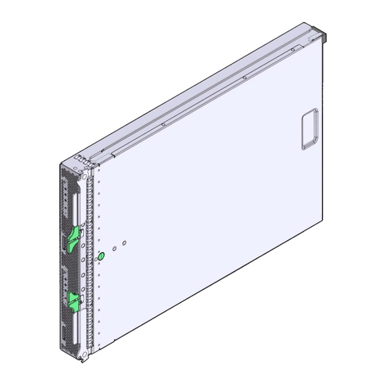
3. Gently press down on the server module cover to engage it with the server module chassis. 4. When applicable, install the server module in the Sun Blade chassis and power on the server module. Installing the Server Module Top Cover FIGURE 4-1 Sun Blade X6275 Server Module Service Manual • September 2013... -
Page 83: Reinstalling The Server Module In The Sun Blade Chassis
Reinstalling the Server Module in the Sun Blade Chassis Caution – After you remove the server module from the chassis, wait for at least 20 seconds before reinserting the server module. If you do not, FMODs might not be recognized by the host compute nodes. If you removed the server module from the chassis, perform these steps to replace it: 1. -
Page 84: Powering On The Server Module
Note – For CMM ILOM 2.0.3.13 systems, a Sun Blade X6275 server module must be inserted into the chassis before you power on. If the blade is not inside the chassis before you power on, ILOM does not recognize node 1. - Page 85 Power-On Procedures TABLE 4-1 Power On Method Apply standby power Place the server module into the chassis. See Section 4.2, “Reinstalling the Server Module in the Sun Blade Chassis” on page 4-3. When the main power is off, the server module green OK LED on the front panel blinks once every three seconds, indicating that the server module is in standby power mode.
- Page 86 Sun Blade X6275 Server Module Service Manual • September 2013...
-
Page 87: Bios Screens
BIOS Screens Configuring BIOS Settings This appendix describes how to view and or modify the BIOS Setup utility screens in Sun Blade X6275 server module The following topics are covered in this appendix: Section A.1, “Configuring BIOS Settings” on page A-1 ■... -
Page 88: Using Bios Menu Items
6. Press and release the right arrow key until the Exit menu screen appears. 7. Follow the instructions on the Exit menu screen to save your changes and exit the Setup utility. Sun Blade X6275 Server Module Service Manual • September 2013... -
Page 89: Bios Setup Utility Screens Overview
A.1.3 BIOS Setup Utility Screens Overview contains summary descriptions of the top-level BIOS setup screens. TABLE A-1 BIOS Setup Screens Summary TABLE A-1 Screen Description See... Main General product information, including BIOS type, processor, Section A.2.1, “BIOS Main memory, and time/date. Menu Screens”... - Page 90 BIOS Utility Menu Tree FIGURE A-1 Sun Blade X6275 Server Module Service Manual • September 2013...
-
Page 91: Bios Setup Menu Screens
BIOS Setup Menu Screens The following figures show sample BIOS Setup utility Sun Blade X6275 server module screens. Note – The screens shown are examples. The version numbers and the screen items and selections shown are subject to change over the life of the product. -
Page 92: Bios Advanced Menu Screens
Note – The term BMC that might be displayed on some screens refers to the SP (service processor). has the following BIOS Advanced screens: Sun Blade X6275 server module Sun Blade X6275 Server Module Service Manual • September 2013... - Page 93 BIOS Setup Utility: Advanced FIGURE A-4 BIOS Setup Utility: Advanced- CPU Configuration FIGURE A-5 Appendix A BIOS Screens...
- Page 94 BIOS Setup Utility: Advanced - SATA Settings FIGURE A-6 BIOS Setup Utility: Advanced- IDE Configuration FIGURE A-7 Sun Blade X6275 Server Module Service Manual • September 2013...
- Page 95 BIOS Setup Utility: Advanced- Third IDE Master Configuration FIGURE A-8 BIOS Setup Utility: Advanced - Event Log FIGURE A-9 Appendix A BIOS Screens...
- Page 96 BIOS Setup Utility: Advanced - View Event Log FIGURE A-10 BIOS Setup Utility: Advanced - Clear Event Log FIGURE A-11 A-10 Sun Blade X6275 Server Module Service Manual • September 2013...
- Page 97 BIOS Setup Utility: Advanced - IPMI Configuration (SP/BMC) FIGURE A-12 BIOS Setup Utility: Advanced - IPMI - View BMC System Event Log (SEL) FIGURE A-13 Appendix A BIOS Screens A-11...
- Page 98 BIOS Setup Utility: Advanced - IPMI - Clear BMC System Event Log FIGURE A-14 BIOS Setup Utility: Advanced - IPMI - LAN Configuration -IP Assignment FIGURE A-15 A-12 Sun Blade X6275 Server Module Service Manual • September 2013...
- Page 99 BIOS Setup Utility: Advanced- Intel VT-d FIGURE A-16 BIOS Setup Utility: Advanced- MPS Configuration FIGURE A-17 Appendix A BIOS Screens A-13...
- Page 100 BIOS Setup Utility: Advanced- Remote Access Type and Parameters FIGURE A-18 BIOS Setup Utility: Advanced- USB Configuration FIGURE A-19 A-14 Sun Blade X6275 Server Module Service Manual • September 2013...
-
Page 101: Bios Pci Menu Screens
BIOS Setup Utility: Advanced- USB Mass Storage Device Configuration FIGURE A-20 A.2.3 BIOS PCI Menu Screens The BIOS PCI screens allow you to clear NVRAM during system boot. The Sun Blade X6275 server module has the following BIOS PCI screens: Appendix A BIOS Screens A-15... - Page 102 BIOS Setup Utility: PCI Settings FIGURE A-21 BIOS Setup Utility: PCI Configuration - Clear NVRAM FIGURE A-22 A-16 Sun Blade X6275 Server Module Service Manual • September 2013...
-
Page 103: Bios Boot Menu Screens
A.2.4 BIOS Boot Menu Screens The BIOS Boot screens allow you to configure the boot device priority (hard disk drives and the DVD-ROM drive). The Sun Blade X6275 server module has the following BIOS Boot screens: BIOS Setup Utility: Boot... - Page 104 BIOS Setup Utility: Boot Settings Configuration FIGURE A-24 BIOS Setup Utility: Boot Device Priority FIGURE A-25 A-18 Sun Blade X6275 Server Module Service Manual • September 2013...
- Page 105 BIOS Setup Utility: Boot Option ROM Enable FIGURE A-26 BIOS Setup Utility: Boot Option ROM FIGURE A-27 Appendix A BIOS Screens A-19...
-
Page 106: Bios Security Menu Screens
FIGURE A-28 A.2.6 BIOS Chipset Menu Screens The BIOS Chipset screens allow you to configure chipset devices (if applicable). has the following BIOS Chipset screens: Sun Blade X6275 server module A-20 Sun Blade X6275 Server Module Service Manual • September 2013... - Page 107 Chipset BIOS Setup Utility: FIGURE A-29 BIOS Setup Utility: Chipset- CPU Bridge FIGURE A-30 Appendix A BIOS Screens A-21...
- Page 108 Chipset - NorthBridge BIOS Setup Utility: Server - FIGURE A-31 BIOS Setup Utility: Server - Chipset - SouthBridge FIGURE A-32 A-22 Sun Blade X6275 Server Module Service Manual • September 2013...
-
Page 109: Bios Exit Menu Screens
The BIOS Exit screens allow you to save changes and exit, discard changes and exit, discard changes, or load optimal or failsafe defaults. The Oracle has the following BIOS Exit screens: Sun Blade X6275 server module BIOS Setup Utility: Exit FIGURE A-33 Appendix A... - Page 110 BIOS Setup Utility: Exit - Save Configuration Changes FIGURE A-34 BIOS Setup Utility: Exit - Discard Changes FIGURE A-35 A-24 Sun Blade X6275 Server Module Service Manual • September 2013...
- Page 111 BIOS Setup Utility: Exit - Discard Changes, Do Not Exit FIGURE A-36 BIOS Setup Utility: Exit - Load Optimal Defaults FIGURE A-37 Appendix A BIOS Screens A-25...
- Page 112 A-26 Sun Blade X6275 Server Module Service Manual • September 2013...
- Page 113 Index Comments, -x Complete power removal, 2-4 accessory kit, 1-11 configuring BIOS, A-1 accessory kit contents, 1-11 contaminants, 1-9 antistatic mat, 2-10 corrupt SP, recovering from, 3-36 antistatic wrist strap, 2-9 CPU, 1-3, 3-17 Apply main power, 4-5 CPU, fault, 3-18 apply power, 4-4 CPUs, 1-10 Apply standby power, 4-5...
- Page 114 ILOM firmware, 3-36 installing to a rack, A-1 Integrated Lights-Out Manager, see ILOM IP addresses, 1-7 rack installation, A-1 IPMI, 1-5 Ready to Remove LED, 1-14 Rear Pane, 1-15 Index-2 Sun Blade X6275 Server Module Service Manual • September 2013...
- Page 115 recovering ILOM firmware using preboot menu, 3- UCP, 1-14 Red Hat Enterprise Linux, 1-4 Universal Connector Port, 1-4 reinstalling server in rack, 4-3 USB Drive, 1-3 remove main power, 2-4 USB drive, 3-15 remove the server module, 2-8 USB port, 1-4 removing FB-DIMMs, 3-8 required tools, 2-2...
- Page 116 Index-4 Sun Blade X6275 Server Module Service Manual • September 2013...
Need help?
Do you have a question about the Sun Blade X6275 and is the answer not in the manual?
Questions and answers