Table of Contents
Advertisement
Quick Links
Advertisement
Table of Contents

Subscribe to Our Youtube Channel
Related Manuals for Iveco daily euro 4


Summary of Contents for Iveco daily euro 4
- Page 1 AILY REPAIR MANUAL MECHANICAL ELECTRIC/ELECTRONIC...
- Page 2 Data and information contained in this document could result not to be updated owing to modifications made by Iveco at any moment for technical or commercial reasons, or because of the need to adapt the vehicle to law requirements in different countries.
- Page 3 PRELIMINARY REMARKS Manuals for repairs are split into Sections, each one of which is marked by a numeral; the contents of these sections are indicated in the general table of contents. Each section is generally dedicated to a main Unit (e.g.: engine, gearbox, electric system, etc.). Sections with mechanical contents include technical data, tightening torque collections, tool lists, connections —...
- Page 4 SYMBOLS - ASSISTANCE OPERATIONS Removal Intake Disconnection Refitting Exhaust Connection Removal Operation Disassembly Fitting in place ρ Compression ratio Assembly Tolerance Tighten to torque Weight difference Tighten to torque + angle value Rolling torque α Press or caulk Rotation Regulation Angle Adjustment Angular value...
- Page 5 PRODUCT CODE Each title or subtitle concerning operations being performed is preceded by a six-figure number named PRODUCT CODE. This number represents the PRODUCT CODE referred to by the repair operation contained in both REPAIR TIMES and TROUBLE CODE document. As a quick reference there are shown below the guide lines to read this code (see Repair Timing, too).
-
Page 6: General Warnings
Avoid to drill or bore pressurised containers, and throw cloths impregnated with inflammable substances into suitable containers. Worn out, damaged or consumable parts must be replaced by Iveco original spares. During workshop activity, always keep the work place clean; timely clear or clean floors from accidental liquid or oil spots. - Page 7 Before washing under pressure mechanical parts, protect electric connectors, and central units, if present. Tightening screws and nuts must always be according to prescriptions; IVECO commercial and assistance network is available to give all clarifications necessary to perform repair interventions not provided in this document.
- Page 8 Do not use a test lamp in checking circuit continuity, but only use proper control apparatuses. Make sure that the electronic devices wiring harnesses (length, lead type, location, strapping, connection to screening braiding, bonding, etc.) comply with IVECO system and are carefully recovered after repair or maintenance interventions.
- Page 9 Bonding and screening Negative leads connected to a system bonded point must be both as short and possible and “star“-connected to each other, trying then to have their centering tidily and properly made (Figure 1, re. M). Further, following warnings are to be compulsorily observed for electronic components: Electronic central units must be connected to system bonding when they are provided with a metallic shell.
- Page 10 OPTIONAL ELECTRICAL AND MECHANICAL PARTS INSTALLATIONS Accessories mounting, additions and modifications on the vehicle are to be performed complying with IVECO mounting instructions (specific document “Instructions for transformation and preparation” is available at Assistance Network workshops). It is reminded that, especially about the electric system, several electric sockets are provided for as series (or optional) sockets in order to simplify and normalise the electrical intervention that is care of preparation personnel.
- Page 11 AILY Print 603.93.651 — 1 edition Base — March 2006 UPDATE DATA Section Description Page Revision date Print 603.93.651 Base - March 2006...
- Page 12 Base - March 2006 Print 603.93.651...
-
Page 13: Table Of Contents
INDEX OF SECTIONS Section General information Engine Clutch Gearbox Propeller shafts Rear axles Front axle Front and rear suspensions Wheels and tyres Steering system Pneumatic system - Brakes Bodywork and chassis frame Maintenance Electric/Electronic System Print 603.93.651 Base - March 2006... - Page 14 Base - March 2006 Print 603.93.651...
- Page 15 GENERAL AILY Print 603.43.671 SECTION 1 General Page IDENTIFICATION DATA ....- Vehicle Identification Plate ....COMPOSITION OF MODELS .
- Page 16 GENERAL AILY Print 603.43.671 Base - March 2006 Print 603.93.651...
- Page 17 GENERAL AILY IDENTIFICATION DATA Figure 1 Vehicle identification plate Plate legend 1) Approval number 2) Chassis number 3) PTT - Total weight on ground 4) MTC - Total combined weight 5) Max. weight permitted on the front axle 6) Max. weight permitted on the rear axle 7) Specific indication of type 8) Wheelbase (mm) 9) Type of engine...
- Page 18 GENERAL AILY COMPOSITION OF MODELS MODELS ASSEMBLIES F1AE0481A*A - F1AE0481A*B (OPT. DPF) 96 CV F1AE0481G*A - F1AE0481G*B (OPT. DPF) 116 CV F1AE0481H*A - F1AE0481H*B (OPT. DPF) 136 CV F1CE0481F*A - F1CE0481F*B (OPT. DPF) 146 CV F1CE0481F*C (DPF series) 146 CV F1CE0481H*A - F1CE0481H*B (OPT.
- Page 19 GENERAL AILY COMPOSITION OF MODELS MODELS ASSEMBLIES F1AE0481A*A - F1AE0481A*B (OPT. DPF) 96 CV F1AE0481G*A - F1AE0481G*B (OPT. DPF) 116 CV F1AE0481H*A - F1AE0481H*B (OPT. DPF) 136 CV F1CE0481F*A - F1CE0481F*B (OPT. DPF) 146 CV F1CE0481F*C (DPF series) 146 CV F1CE0481H*A - F1CE0481H*B (OPT.
- Page 20 GENERAL AILY ALPHANUMERICAL CODING FOR VEHICLE IDENTIFICATION CUSTOMIZED VEHICLE (V.P.) MARKET VEHICLE (V.M.) STANDARD VEHICLE (V.C.B.) 9 10 11 12 13 14 RANGE 9 10 11 12 13 14 LIGHT ROAD VEHICLES PROGRAMMING FAMILY 9 10 11 12 13 14 T 25C 29 L T 30C...
- Page 21 GENERAL AILY PROGRAMMING FAMILY 9 10 11 12 13 14 T 25V 29 L T 30V 35 C T 35V 35 C VANS AND DERIVATIVES T 40V 40 C 50 C T 50V 45 C 60 C T 65V 65 C ENGINE 9 10 11 12 13 14 F1A E4 LD - 96 CV...
- Page 22 GENERAL AILY SUSPENSION 9 10 11 12 13 14 Mechanical suspension: front with transverse leaf spring. Mechanical suspension: front with torsion bars. Mechanical front suspension with transverse leaf spring — rear air suspension. Mechanical front suspension with torsion bars — rear air suspension. VERSION 9 10 11 12 13 14 29 L10 (•) - 29 L12 (•) - 29 L14 (•)
- Page 23 GENERAL AILY VERSION 9 10 11 12 13 14 35 C10 CA (•) - 35 C12 CA (•) 35 C10 CA (•) - 35 C12 CA (•) 40 C10 CA (•) - 40 C12 CA (•) 40 C10 CA ( ) 40 C12 CA ( ) CUT-AWAY CUT-AWAY 45 C18 CA (•) - 50 C18 CA (•)
- Page 24 GENERAL AILY WHEELBASE 9 10 11 12 13 14 3000 mm (T25C - T30C - T35C - T40C - T25V - T30V - T35V - T40V - T50V) 3000 L mm (T25V - T30V - T35V - T40V - T50V) 3300 mm (T25V - T30V - T35V - T40V - T50V) 3450 mm...
- Page 25 GENERAL AILY GEARBOX 9 10 11 12 13 14 5 SPEED (5 S 300) 6 SPEED (6 S 400 O.D.) 6 SPEED (6 S 400 A O.D.) Automated O.D. Over Drive Print 603.93.651 Base - March 2006...
- Page 26 GENERAL AILY DRIVE — INTERNAL HEIGHT OF LOADING BAY 9 10 11 12 13 14 LEFT-HAND DRIVE (T25C - T30C - T35C - T40C - T50C) LEFT-HAND DRIVE AND INTERNAL HEIGHT OF LOADING BAY H = 1545 mm (T25V - T30V - T35V - T40V - T50V) LEFT-HAND DRIVE AND INTERNAL HEIGHT OF LOADING BAY H = 1900 mm...
- Page 27 GENERAL AILY REPLENISHING FLUIDS IVECO RECOMMENDED LUBRICANTS PARTS TO BE REPLENISHED Quantity Litres Quantity of oil in circulation in the car- 1.23 tridge filter and heat exchanger 5.02 Total dry engine capacity Sump capacity: 3.78 - max level Urania Daily 2.65...
- Page 28 Hydraulic brake and clutch control fluid Tutela TRUCK DOT SPECIAL In conformity with N.H.T.S.A. standards No. 116, ISO 4925 Standard SAE J 1703, IVECO STANDARD 18-1820 Windscreen washer liquid Tutela Professional SC 35 Mixture of spirits, water and surfactants CUNA NC 956-11...
- Page 29 F1A ENGINE AILY SECTION 2 5401 Engine Page F1A ENGINE ......F1C ENGINE .
- Page 30 F1A ENGINE AILY Base - March 2006 Print 603.93.651...
- Page 31 F1A ENGINE AILY F1A Engine Page MAIN OPERATIONS ON ENGINE MOUNTED ON VEHICLE ......- Service procedures to be performed after replacing high-pressure feeding system and/or exhaust gas post- treatment system components .
- Page 32 F1A ENGINE AILY Page Page - Removal ......- Measuring main journals and crank pins .
- Page 33 F1A ENGINE AILY Page Page - Boring valve guides ..... . - Turbocharger (KKK K03-2074-CCB 5.88 type) VALVE SEATS ......REPAIRS .
- Page 34 F1A ENGINE AILY Page Page - Fuel pump ......- Immobilizer recognition ....- Checking fuel temperature .
- Page 35 Keep to the following instructions before doing any work on the engine involving components of the fuel supply system. - Before doing any work on the engine, perform the engine/vehicle fault diagnosis with specific IVECO diagnosis equipment and print out the results.
- Page 36 - performing forced regeneration, the control unit shall be programmed again by means of the IVECO MODUS - E.A.SY. - IT 2000 diagnosis instrument, and the replacement procedure for the concerned component shall be performed, in accordance with the indications of the diagnosis instruments used.
- Page 37 F1A ENGINE AILY 540110 POWER UNIT REMOVAL/REFITTING Removal Figure 1 Place the vehicle on the pit or auto lift. Lift the engine hood (28), undo the fastening screws (28) and then remove the hood; remove supporting rod (30). Disconnect negative cable (11) and positive cable (4) from battery (10), then remove the latter from the engine compartment.
- Page 38 F1A ENGINE AILY Remove nuts (23), then properly place remote-control Figure 2 switch/fuse holder (22) aside. Disconnect pipe (21) from the heat exchanger and the turboblower. Disconnect pipe (13) from the heat exchanger and the throttle valve assembly. NOTE Properly obstruct the turboblower air outlet to avoid casual penetration of foreign bodies into the turboblower and, therefore, damage to the latter.
- Page 39 F1A ENGINE AILY Disconnect cab heater pipe (23) from E.G.R. exchanger outlet Figure 3 pipe (22). Disconnect: - vacuum pipe (27) from the E.G.R. valve; - pipe (1), from coalescence filter (25); - pipe (21), from pipe (19). Disconnect electric connection (15) from air flow meter (16). Remove air pipes (14 and 19), together with air flow meter (16), from turboblower (20) and air filter (13).
- Page 40 F1A ENGINE AILY Act from under the vehicle: Figure 4 to disconnect jointed heads (17) of lever shift control cables (16); selection cable (max. pull-out load: 250 N - max. pull-in load: 60 N); engagement cable (max. pull-out load: 100 N - max. pull-in load: 80 N).
- Page 41 F1A ENGINE AILY Refitting NOTE When positioning the engine in the engine bay, take special care not to damage the top pipe of the power steering and the soundproof-heatproof To refit the engine assembly, carry out the operations cladding of the engine bay. described for removal in reverse order, following these Once positioned, meticulously check that the top instructions:...
- Page 42 F1A ENGINE AILY REPLACING BELTS 543910 Replacing air-conditioning compressor drive belt Disassembly Figure 5 90155 Cut elastic belt (3), as it cannot be reused. Assembly Fit the flexible belt (3) equipped with tool 99360191 (2) on the pulley (4) and apply the tool on the pulley (1). Fit the drive ring (5) on the flexible belt (3) and fasten the ring on the compressor support.
- Page 43 F1A ENGINE AILY 541257 Replacing timing drive belt Figure 7 Disassembly Remove, by following the power unit detachment procedures, the radiator assembly together with the heat exchanger and the drying filter condenser (if any), then place it aside properly. Remove the air-conditioner compressor drive belt (11) (if there is one) and the water pump / alternator drive belt as described under the relevant headings.
- Page 44 F1A ENGINE AILY Figure 8 Assembling Only for the engines featuring intake valve distributing shafts with NOTE tapered shank (full section). Insert tool 99360608 (8) into the hole of the toothed pulley (7) and into the corresponding hole of the overhead to prevent changing the assembly position of the toothed pulley (7) in the following operations.
- Page 45 1. IMA Matrix code- 2. Bosch spare part no. - checks on electrical injectors minimum flow rate. 3. IMA code in clear - 4. Iveco spare part no. - 5. Code - In certain conditions (overrun: vehicle deceleration with 6. Series no. - 7. Production date...
- Page 46 F1A ENGINE AILY Figure 11 Removal 108559 Partly drain the coolant off from the radiator. Refitting Remove the plug (21, Figure 9) and detach the soundproofing cover (20, Figure 9). Disconnect the pipes (19, Figure 9) from the pipe (18, Thoroughly clean the seat of the electro-injectors, taking care Figure 9).
- Page 47 F1A ENGINE AILY 540610 CYLINDER HEAD REMOVAL AND REFITTING Figure 12 108560 Removal Take off electric injectors (4), as described in the ”Replacing Take off the camshaft drive belt, as described in the the electric injectors” chapter (operation 775010). respective chapter (operation 541257). Disconnect the electric connections from phase sensor (3), Disconnect coolant pipes (15) and (14) from pipe (13).
- Page 48 F1A ENGINE AILY Figure 13 108561 Take out the screws and remove the overhead together with Loosen clamp (9), then take the air conveyor off. the pins 99360614. Take air suction sleeve (10) off turboblower (8). Disconnect the oil pipe (11) from the cylinder head and from the turbocharger (8).
- Page 49 F1A ENGINE AILY Figure 14 Refitting Refitting requires carrying out the operations for removal in reverse order, while taking the following precautions: Check that the timing tools: 99360614 (6, Figure 13) and 99360608 (8, Figure 13) are inserted in the overhead; 99360615 (11, Figure 13) is inserted in the crankcase as described in “Replacing timing belt.”...
- Page 50 F1A ENGINE AILY 771010 REPLACING HIGH-PRESSURE PUMP CPH1 Figure 17 Removal Remove the timing drive belt, as described in the relevant chapter (operation 541257). Disconnect the following items: electric connection from the pressure sensor; fuel pipes from the high-pressure pump. Figure 15 75273 Take out the screws (1) and remove the high-pressure pump...
- Page 51 F1A ENGINE AILY THROTTLE VALVE ASSEMBLY REMOVAL- REFITTING Figure 21 Removal Figure 19 108564 Remove nuts (2) securing pipe (3) to throttle valve assembly (1). Loosen screws (4) securing pipe (3) to heat exchanger (5), then take throttle valve assembly (1) off the inlet manifold. Refitting 108562 For refitting, reverse the operations described for...
- Page 52 F1A ENGINE AILY 5407 E.G.R. VALVE REMOVAL/REFITTING Remove nut (4) used for upper securing of throttle valve Removal assembly (5) connecting pipe (9) to heat exchanger (7). Figure 23 Lower fastening nut (6) shall be removed from under the vehicle. Act from under the vehicle to remove the heat exchanger supporting and engine lifting bracket (8) fastening screws.
- Page 53 F1A ENGINE AILY BURNT GAS EXHAUST SYSTEM 507130 OXICAT - OXYDIZER CATALYST Description Description The following exhaust systems are available on light-duty (LD) vehicles with a total weight on ground (P.T.T.) of up to The oxidizing catalyst (1) is a post-treatment device for ex- 2,840 kg: haust gases.
- Page 54 F1A ENGINE AILY The optional exhaust system is made up of three components: A. system length with hose; B. catalyst with particulate filter (DPF); C. silencer This system is manufactured by ArvinMeritor (ArM). Figure 27 108626 Base - March 2006 Print 603.93.651...
- Page 55 F1A ENGINE AILY EXHAUST PIPE ASSEMBLY REMOVAL/REFITTING Figure 28 108627 Refitting Removal For refitting, reverse the operations described for disconnection observing following warnings: Place the vehicle on a pit or auto lift. - check the conditions of the elastic dowels, Disconnect oxygen sensor electric connection (4).
- Page 56 F1A ENGINE AILY REMOVAL/REFITTING OF EXHAUST PIPE ASSEMBLY COMPONENTS (SYSTEMS EQUIPPED WITH D.P.F. CATALYST) Figure 29 105073 Refitting For refitting, reverse the operations described for disconnection observing following warnings: Exhaust silencer removal - check the conditions of the elastic dowels, Place the vehicle on a pit or auto lift.
- Page 57 The meters used to evaluate the above-mentioned counter is not reset, there may be an early request to refill parameters can be reset by means of the IVECO MODUS - engine oil. E.A.SY. - IT 2000 diagnosis instruments, by programming the...
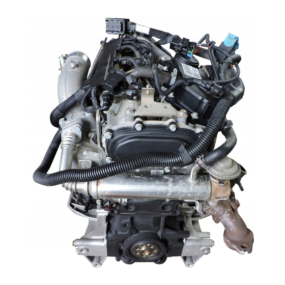
- Page 58 F1A ENGINE AILY ENGINE VIEWS Figure 30 108321 Base - March 2006 Print 603.93.651...
- Page 59 F1A ENGINE AILY Figure 31 Figure 33 108157 108159 LEFT-HAND SIDE VIEW FRONT VIEW Figure 32 108158 REAR VIEW Print 603.93.651 Base - March 2006...
- Page 60 F1A ENGINE AILY Figure 34 108160 RIGHT-HAND SIDE VIEW A. Turbocharger with pressure relief valve (Waste-Gate, ENGINES 96/116 HP) Figure 35 108161 TOP VIEW Base - March 2006 Print 603.93.651...
- Page 61 F1A ENGINE AILY EMISSIONS Gas emissions Smokiness The engines conform to the Euro 4 standards on gas The engines conform to the limits of smokiness required with emissions (measurement on engine bench according to ECE the following exhaust smoke values: 15 + EUDC cycle), with the following limits fixed by the ESC Maximum power (Bosch BSU opacimeter degrees) and ELR 1999/96-2001/27 standards:...
- Page 62 F1A ENGINE AILY ENGINE IDENTIFICATION CODE Emission level Type approval power Use No. Supply / injection No. cylinders Engine cycle — cylinder position Engine Family development 0= 4-stroke, vertical Engine family 4 = 4 cylind. 6 = 6 cylind. 8 = DI. TCA 1 = Truck 2 = Bus 4 = E.M.
- Page 63 F1A ENGINE AILY CHARACTERISTIC CURVES Figure 36 102408 CHARACTERISTIC CURVES OF ENGINE F1AE0481F 96 HP Max OUTPUT 71 kW at 3000÷3700 rpm 24.4 kgm Max TORQUE 240 Nm at 1800÷2800 rpm Print 603.93.651 Base - March 2006...
- Page 64 F1A ENGINE AILY Figure 37 102409 CHARACTERISTIC CURVES OF ENGINE F1AE0481G 116 HP Max OUTPUT 85 kW at 3000÷3900 rpm 27.5 kgm Max TORQUE 270 Nm at 1800÷2800 rpm Base - March 2006 Print 603.93.651...
- Page 65 F1A ENGINE AILY Figure 38 102410 CHARACTERISTIC CURVES OF ENGINE F1AE0481H 136 HP Max OUTPUT 100 kW at 3600÷3900 rpm 31.6 kgm Max TORQUE 320 Nm at 1700÷2900 rpm Print 603.93.651 Base - March 2006...
- Page 66 Figure 40 CRANKCASE MARKING 112216 EXAMPLE A = IVECO trademark IVECO = IVECO name of engine variant ** F1AE0481A * A001 C = Engine serial number 1359862 D = 1 digit, main journal no. 1 (engine front) = Main bearing selection diameters...
- Page 67 F1A ENGINE AILY GENERAL SPECIFICATIONS Type F1AE0481 F F1AE0481 G F1AE0481 H Cycle Diesel 4 strokes Supply Turbocharged with intercooler Injection Direct Number of cylinder 4 in line ∅ Bore Stroke +.. = Total displacement 2300 ρ Compression ratio Maximum power (HP) (96) (116)
- Page 68 F1A ENGINE AILY Type F1AE0481 F F1AE0481 G F1AE0481 H TIMING SYSTEM Start before T.D.C. 14° end after B.D.C. 27° Start before T.D.C. 54° end after B.D.C. 10° For timing check Operation High pressure fuel feed system BOSCH EDC16 Composed of CP1 high-pressure pump, electro-injectors, SUPPLY hydraulic accumulator (rail), EDC control unit, pressure and temperature sensors...
- Page 69 F1A ENGINE AILY Type F1AE0481 F F1AE0481 G F1AE0481 H TURBOCHARGING With intercooler KKK K03-2074-CCB 5.88 Garrett GT17 Turbocharger type Turbocharger type Turbocharger shaft radial play Turbocharger shaft end float 3.35 ±0.5 Maximum stroke of pressure relief valve opening 1.6 ±0.005 Pressure corresponding to the maximum stroke Actuator calibration: -vacuum: 0 mmHg...
- Page 70 F1A ENGINE AILY ASSEMBLY DATA — CLEARANCES Type F1AE0481 F F1AE0481 G F1AE0481 H CYLINDER ASSEMBLY AND CRANK MEMBERS Cylinder liners: ∅ 1 88.002 ÷ 88.022 ∅ 1 Cylinder liners: ∅ outside diameter length ∅ 2 Cylinder liners — crankcase seats (interference) ∅...
- Page 71 F1A ENGINE AILY Type F1AE0481 F F1AE0481 G F1AE0481 H CYLINDER ASSEMBLY AND CRANK MEMBERS Type of piston MAHLE MONDIAL MAHLE MONDIAL 2 200 ÷ 2 230 2.200 ÷ 2.230 Piston ring slots 2 050 ÷ 2 070 2.050 ÷ 2.070 2 540 ÷...
- Page 72 F1A ENGINE AILY Type F1AE0481 F F1AE0481 G F1AE0481 H CYLINDER ASSEMBLY AND CRANK MEMBERS Measurement Maximum error on alignment of 0.09 connecting rod axes ∅ 1 Main journals ∅ ∅ 71.182 ÷ 71,208 No. 1-2-3-4 76.182 ÷ 76.208 No. 5 ∅...
- Page 73 F1A ENGINE AILY Type F1AE0481 F F1AE0481 G F1AE0481 H CYLINDER HEAD — TIMING SYSTEM ∅ 1 Guide valve seats ∅1 9.980 ÷ 10.000 on cylinder head ∅ 6.023 ÷ 6.038 ∅ 2 ∅ 2 Valve guide ∅ 3 10.028 ÷ 10.039 ∅...
- Page 74 F1A ENGINE AILY Type F1AE0481 F F1AE0481 G F1AE0481 H CYLINDER HEAD — TIMING SYSTEM 0.08 - 0.12 Between valve Between valve seat and head 0.08 - 0.12 Valve seats Valve spring height: free height under a load of: H 2 N243 ± 12 N533 ±...
- Page 75 F1A ENGINE AILY TOOLS TOOL NO. DESCRIPTION 99305047 Appliance to check spring loads 99317915 Set of six box-type wrenches (14-17-19 mm) Rotary telescopic stand for overhauling assemblies 99322205 (capacity 700 daN, torque 120 daN/m) 99340028 Extractor for camshaft pulley 99340035 High-pressure pump toothed pulley extractor 99340059 Tool to remove crankshaft front gasket...
- Page 76 F1A ENGINE AILY TOOLS TOOL NO. DESCRIPTION 99340058 Tool to remove crankshaft rear gasket 99342153 Tool to extract injectors 99346254 Keying device for mounting crankshaft front gasket Keying device for mounting crankshaft rear gasket 99346255 99360076 Tool to remove cartridge filters 99360183 Pliers for mounting rings on engine pistons Base - March 2006...
- Page 77 F1A ENGINE AILY TOOLS TOOL NO. DESCRIPTION 99360191 Guide for flexible belt 99360260 Tool for removing and refitting engine valves 99360306 Tool to retain engine flywheel 99360544 Arm for removing and refitting engine 99360605 Band to insert standard and oversized pistons into the cylinders 99360608 Tool for positioning timing gear Print 603.93.651...
- Page 78 F1A ENGINE AILY TOOLS TOOL NO. DESCRIPTION 99360614 Tool (2) for camshaft timing 99360615 Tool for crankshaft timing 99361038 Brackets securing engine to rotary stand 99322205 99367121 Manual pump to measure pressure and vacuum Comparator holder base 99370415 Keying device for mounting oil seal gasket on camshaft front cover 99374458 Base - March 2006 Print 603.93.651...
- Page 79 F1A ENGINE AILY TOOLS TOOL NO. DESCRIPTION 99389819 Torque wrench (0-10 Nm) with square 1/4” connection 99389829 9x12 coupling torque wrench (5-60 Nm) Milling cutter to regrind injector seat 99394038 (8140.63 engine excluded) Pair of meters for angular tightening with square 1/2” and 3/4” 99395216 connection 99395363...
- Page 80 F1A ENGINE AILY TOOLS TOOL NO. DESCRIPTION 99395687 Bore meter (50 — 178 mm) Device for checking belt tension 99395849 (frequency from 10.0 to 600 Hz) Centring ring for crankshaft front gasket cover 99396037 EXPERIMENTAL TOOLS This section shows the working drawings for the experimental tools (S.P.) used in overhauling the engine described in this section, which may be made by the repair shops.
- Page 81 F1A ENGINE AILY Print 603.93.651 Base - March 2006...
- Page 82 F1A ENGINE AILY Base - March 2006 Print 603.93.651...
- Page 83 F1A ENGINE AILY Print 603.93.651 Base - March 2006...
- Page 84 F1A ENGINE AILY Base - March 2006 Print 603.93.651...
- Page 85 F1A ENGINE AILY Print 603.93.651 Base - March 2006...
- Page 86 F1A ENGINE AILY Base - March 2006 Print 603.93.651...
- Page 87 F1A ENGINE AILY Print 603.93.651 Base - March 2006...
- Page 88 F1A ENGINE AILY Base - March 2006 Print 603.93.651...
- Page 89 F1A ENGINE AILY Print 603.93.651 Base - March 2006...
- Page 90 F1A ENGINE AILY Base - March 2006 Print 603.93.651...
- Page 91 F1A ENGINE AILY TIGHTENING TORQUE TORQUE PART PART Cylinder head central fixing screw M14x1.5 first phase: pre-tightening second phase: angle 90º third phase: angle 90º Cylinder head side fixing screw M14x1.5 first phase: pre-tightening second phase: angle 60º third phase: angle 60º...
- Page 92 F1A ENGINE AILY TORQUE PART PART Tapered threaded socket plug R 3/8” x 10 Tapered threaded socket plug R 1/8” x 8 Tapered threaded socket plug R 1/4” x 9 Hex screw with flange M12x1.25 L35 fixing gear for camshaft chain 11.5 Hex screw with flange M6x1 L25 fixing chain cover Hex screw with flange M6x1 L35 automatic tightener...
- Page 93 F1A ENGINE AILY TORQUE PART PART Pipe fitting M12x1.5 to secure electric injectors side and high pressure pump side piping 25 ± 2 2.5 ± 0.2 (welded hydraulic accumulator) Pipe fitting M14x1.5 to secure hydraulic accumulator side piping 19 ± 0.2 1.9 ±...
- Page 94 F1A ENGINE AILY Figure 41 108442 LONGITUDINAL CROSS-SECTION OF ENGINE Base - March 2006 Print 603.93.651...
- Page 95 F1A ENGINE AILY Figure 42 108443 TRANSVERSE CROSS-SECTION OF ENGINE Print 603.93.651 Base - March 2006...
- Page 96 F1A ENGINE AILY OVERHAULING ENGINE 540110 DISASSEMBLING THE ENGINE Fit the brackets 99361038 (9) to the crankcase and use these to secure the engine to the rotary stand 99322205 (6). Drain AT THE BENCH the oil from the engine by removing the plug from the oil Figure 43 sump.
- Page 97 F1A ENGINE AILY ssll Figure 45 Figure 48 108164 108165 Take out the bolt (1), the bottom screws (3 and 4) and Cut compressor (2) drive elastic belt (1),as it cannot be remove the alternator (2) from the mounting (5). reused.
- Page 98 F1A ENGINE AILY Figure 51 Figure 54 108168 Remove screws (2),then take bracket (1) off. 75253 Remove screws (4), then take oil filling pipe union (3) off. Take out the screws (1) and remove the timing cover (2). Figure 52 Figure 55 75254 Take out the screw (3) and remove the tightener (4).
- Page 99 F1A ENGINE AILY Figure 57 Figure 60 108174 108171 Loosen clamp (6), then disconnect fuel pipe (5) from Take out the screws (2) and the brackets (3) fixing the high-pressure pump (7). electro-injectors (1) to the cylinder overhead. Remove screw (3) securing pipe (2) retaining bracket (4) to the inlet manifold.
- Page 100 F1A ENGINE AILY Figure 63 Figure 65 108177 108179 Loosen clamp (7), then disconnect pipe (6) from EGR valve Remove screw (4), then disassemble air pressure/temperature (8). sensor (3). Loosen clamp (4), then disconnect pipe (5) from heat Remove screws (1), then take off inlet manifold (2) together exchanger (3).
- Page 101 F1A ENGINE AILY Figure 68 Figure 71 108185 108182 Remove screw (2), then take off pipe union (1). Take out the screws (1) and remove the overhead (2). Remove screws (3) securing elbow (4) to bracket (5). Figure 72 Figure 69 75269 Take off the gasket (1) and remove the hydraulic tappets together with the rocker arms (2).
- Page 102 F1A ENGINE AILY Figure 74 Figure 77 75274 Take out the screws (1) and remove the water pump 75271 assembly (2). Block rotation of the high-pressure pump gear (1) by applying Figure 78 tool SP 2263 (2) as shown in the figure. Take off the nut (3) and remove the tool (2).
- Page 103 F1A ENGINE AILY Figure 80 Figure 83 108187 108188 Using tool 99360076 (2), remove the oil filter (1). Take out the screw (2) and remove the speed sensor (1). Take out the screws (4) and remove the compressor mounting (3). Figure 81 Figure 84 75278...
- Page 104 F1A ENGINE AILY Figure 86 Figure 88 75283 Take out the screws (2), (3), (4) and (5) and remove the 75285 suction strainer (1) together with the pipe (6). Block rotation of the flywheel (1) with tool 99360306 (3). Take out the screws (2) and remove the engine flywheel (1). Take out the screw (5) and remove the guard (4).
- Page 105 F1A ENGINE AILY Figure 90 Figure 93 75287 Using an appropriate wrench and a hex-fluted wrench, unscrew the screws (1) and (2) and remove the crankcase base (3). 75290 Figure 91 Take out the couplings (1) and remove the oil jets (2). NOTE On completing engine removal, it is necessary to clean the removed parts thoroughly and check...
- Page 106 Apply LOCTITE 270 sealant (IVECO NO. 93162429) to the caps when fitting the diameter of the pistons supplied as spare parts oversized by 0.4 mm of the nominal value and to the prescribed...
- Page 107 F1A ENGINE AILY Checking head mating surface on cylinder 5408 CRANKSHAFT block 540810 Measuring main journals and crank pins Figure 98 Figure 100 75296 See that the head mating surface, on the cylinder block, has 75298 no deformation. On finding signs of seizure, scoring or excessive ovalization This check can be made, after taking out the grub screws (3), on main journals and crankpins, it is necessary to regrind the with a surface plate spread with carbon black or with a...
- Page 108 F1A ENGINE AILY Checking crankshaft Figure 101 75299 MAIN CRANKSHAFT TOLERANCES TOLERANCES TOLERANCE CHARACTERISTIC SYMBOL ○ Circularity SHAPE SHAPE Cylindricality Parallelism DIRECTION DIRECTION ⊥ Perpendicularity Concentricity or coaxiality OF POSITION ↗ Circular oscillation OSCILLATION OSCILLATION ↗↗ Total oscillation CLASS OF IMPORTANCE ASCRIBED TO THE PRODUCT CHARACTERISTICS SYMBOL CRITICAL ⊕...
- Page 109 F1A ENGINE AILY JOURNAL ON TIMING SYSTEM SIDE JOURNAL ON FLYWHEEL SIDE Figure 103 Figure 106 honed honed waviness in circumferential direction waviness in axial direction 108189 RACE AREA FOR ALL MAIN JOURNALS 75303 (MACHINED BY TURNING) INTERMEDIATE JOURNALS No. 2-4 CRANKPINS Figure 107 Figure 104...
- Page 110 F1A ENGINE AILY Assembling main bearings Figure 108 Figure 110 75305 Take out the screws (4) and replace the phonic wheel (3). 75307 The screws (4) hey must be tightened to a torque of 15 Nm. NOTE Not having found it necessary to replace the main Replacing timing control gear bearings, they need to be fitted back on in the same On finding the timing control gear teeth (1) damaged or...
- Page 111 F1A ENGINE AILY Figure 112 Figure 114 75288 75310 - Remove the bottom crankcase. Thoroughly clean the bottom main bearing shells (2) and mount them in the crankcase base (1) The clearance between the main bearings and their associated pins is measured by comparing the length of the calibrated wire (1), at the point of greatest crushing, with the graduated scale on the casing containing the calibrated wire.
- Page 112 Figure 117 α 85843 Carefully clean the seal seat. Apply LOCTITE 510 IVECO nr. 2992504 on the seal (1) for 30° in the points shown in the figure. 75309 Lubricate the rear shank of the crankshaft with engine oil.
- Page 113 F1A ENGINE AILY 540850 ENGINE FLYWHEEL 540852 Replacing bearing supporting gear- Figure 120 box input shaft Figure 122 108194 Use a suitable beater to take off engine flywheel bearing (1), 75389 taking care that the bearing does not set itself sideways or get stuck, with resulting flywheel housing damage.
- Page 114 F1A ENGINE AILY 540840 Pistons Figure 124 Disassembly Figure 125 α 75391 Fit tool 99360351 (4) onto the crankcase to block rotation of the engine flywheel (1). 75393 Tighten the screws (3) fixing the engine flywheel (1) in two Remove the piston rings (1) from the piston (2) using pliers steps: 99360183 (3).
-
Page 115: Piston Rings
F1A ENGINE AILY Conditions for correct pin-piston coupling Measuring piston diameter Figure 128 Figure 131 108195 Use a micrometer (2) to measure plunger (1) diameter, in order to determine the assembling play. The diameter shall be measured at such a distance from the plunger base as shown in the figure. - Page 116 F1A ENGINE AILY Figure 134 Figure 137 74948 Check the clearance between the trapezoidal ring (2) (1 75399 slot) and the associated slot on the piston with a feeler gauge Check the opening between the ends of the piston rings (2) (1), proceeding as follows: insert the piston into the cylinder inserted in the cylinder liner using a feeler gauge (1).
- Page 117 F1A ENGINE AILY 540834 Bushes Checking bending Check that the bush in the small end has not come loose and Figure 141 shows no sign of seizure or scoring. If it does, replace the complete connecting rod. Checking connecting rod Figure 139 61695 Check the bending of the connecting rod (5) by comparing...
- Page 118 F1A ENGINE AILY After fitting the connecting rod — piston assembly together, Figure 143 check for distortion with the tool 99395363 (8) as follows: - Fit the connecting rod (7) together with the piston (3) on the spindle (4) of tool 99395363 (8) and lock it with the screw (5).
- Page 119 F1A ENGINE AILY - The openings of the piston rings are staggered 120° apart. - Remove the cap (2) and determine the existing clearance by comparing the width of the calibrated wire (3, - The pistons are all of the same weight. Figure 148) with the graduated scale on the case (2, - The symbol punched on the top of the pistons faces the Figure 148) that contained the calibrated wire.
-
Page 120: Removing Valves
F1A ENGINE AILY 541210 Removing valves Figure 152 Figure 154 75412 75410 Fit part (4) of tool 99360260 onto the cylinder head (5) and Fit the gasket (4) and the frame (3) onto the oil sump (1). secure it with the screws (3). Screw down the fixing screws (2) and tighten them to the prescribed torque. - Page 121 F1A ENGINE AILY 540662 VALVES Checking cylinder head seal Figure 157 Check the hydraulic seal using a suitable tool. Pump in water heated to approx. 90°C at a pressure of 2 ÷ EXHAUST INTAKE VALVE VALVE 3 bars. Replace the cup plugs if they are found to leak at oil, using a suitable drift for their removal —...
- Page 122 F1A ENGINE AILY Checking clearance between valve stem and Figure 162 valve guide and centring valves Figure 160 75455 Remove the valve guides (2) with the drift SP.2312 (1). 75453 Figure 163 The checks are made using a dial gauge (2) with a magnetic base, positioned as illustrated.
- Page 123 F1A ENGINE AILY 540661 VALVE SEATS Recutting and replacing valve seats Figure 165 108198 Check the valve seats. On finding any slight scoring or burns, Mount the valves, block the seat of the electro-injectors and regrind them with an appropriate tool according to the glow plugs;...
- Page 124 F1A ENGINE AILY 540665 VALVE SPRINGS ROCKER ARMS — TAPPETS Figure 168 Figure 170 62386 Before assembly, check the flexibility of the valve springs with the tool 99305047. Compare the load and elastic deformation data with those of the new springs given in the following figures.
- Page 125 F1A ENGINE AILY Figure 172 75462 MAIN DATA HYDRAULIC TAPPETS — SEATS Figure 174 Checks The sliding surface of the tappets must have no scoring/dents; replace them if they do. Using a micrometer, measure the diameter of the tappets and, using a bore meter, measure the diameter of the seats in the cylinder head;...
- Page 126 F1A ENGINE AILY Figure 175 Figure 177 75466 108323 Only engines with intake distributing shaft con tapered shank. Using the extractor 99340028 (2) extract the toothed pulley Fit the thermostat casing (2) with a new seal and tighten the (1) driving the camshaft. fixing screws (3) to the prescribed torque.
- Page 127 F1A ENGINE AILY 5412 TIMING SYSTEM Figure 180 Figure 183 75469 Take out the screws (1) and remove the rear cover (2) together with its gasket. Figure 181 75472 1. Camshaft on intake side — 2. Hydraulic tightener — 3. Camshaft on exhaust side — 4. MORSE chain — 5.
- Page 128 F1A ENGINE AILY 541210 Camshaft 541211 Checking cam lift and pin alignment Checks The surfaces of the shaft supporting pins and of the cams Figure 186 must be finely honed; if there is any sign of meshing or scoring, replace the shaft. Figure 185 75475 75474...
- Page 129 F1A ENGINE AILY Figure 188 108199 MAIN SPECIFICATIONS, HOLLOW-SECTION DISTRIBUTING SHAFT SEATS AND PINS 1. Intake valve camshaft seats — 2. Exhaust valve camshaft seats — 3. Exhaust valve camshaft — 4. Intake valve camshaft. Print 603.93.651 Base - March 2006...
- Page 130 F1A ENGINE AILY Assembling overhead Figure 192 Figure 189 α 75471 75479 Lubricate the supporting pins of the shafts (2 and 3) and fit Fit the chain drive (2) on the camshafts and secure it to the them in the overhead (1). overhead (1) tightening the screws (8) to the prescribed torque.
- Page 131 F1A ENGINE AILY Figure 194 NOTE The toothed pulley (1, Figure 196) for the intake shaft with full-section tapered shank is not locked on the shaft since it must be able to turn when fitting and tensioning the timing belt. For the same reason, keep the tools 99360608 (4, Figure 196) and 99360614 (3, Figure 190) fitted.
- Page 132 F1A ENGINE AILY Figure 199 Figure 201 108188 75484 Lubricate the shank of the crankshaft. Mount the speed sensor (1) with a fresh gasket and tighten the fixing screw (2) to the prescribed torque (if applicable). Screw down part (3) of tool 99346254 in the crankshaft and place the seal (2) on the part (3).
- Page 133 F1A ENGINE AILY Figure 204 Figure 207 108187 Lubricate the seal of the oil filter (1) with engine oil. Using tool 99360076 (2), tighten the oil filter to the 75490 prescribed torque. Fit the high-pressure pump (2) onto the flange of the water pump (1) and tighten the fixing screws (3) to the prescribed torque.
- Page 134 F1A ENGINE AILY Refitting cylinder head Figure 209 Figure 211 α 75491 Check that tool 99360619 (2) inserted in the hole (→) of the 75493 oil vacuum pump assembly (1) blocks crankshaft rotation. Mount the cylinder head (1). This condition is necessary for setting up the timing system Screw down the fixing screws (3) and tighten them, in three and to prevent the valves interfering with the pistons.
- Page 135 F1A ENGINE AILY Figure 213 Figure 216 75495 Thoroughly clean the hydraulic tappets (2), lubricate them and fit them in the cylinder head (3), positioning the rocker arms (1) 85844a on the valves correctly. X = Direction of movement of the tightener — Fit on the gasket (5).
- Page 136 F1A ENGINE AILY Figure 219 NOTE Do not turn the engine in the opposite direction; if, on turning the engine, you pass the point for inserting the tools (6) and (11), turn the engine clockwise by another two turns. See frame C: Figure 216, holding the tightener plate (3) stationary with the wrench inserted in its hexagon, loosen the fixing screw (2).
- Page 137 F1A ENGINE AILY Figure 222 Figure 225 75501 Mount the fixed tightener (2) and tighten the fixing screw (1). Mount the automatic tightener (3) and tighten the screw (4) 75503 to the prescribed torque. Fit a new seal (3) on the electro-injector (1) and mount this in the overhead (2).
- Page 138 F1A ENGINE AILY Figure 228 Figure 231 108329 Connect the fuel pipes (2) to the electro-injectors (1) and to the hydraulic accumulator (3). 108331 Tighten the screws (4) fixing the electro-injector brackets to the prescribed torque. Mount the intake manifold (1) with a new gasket and, using a torque wrench, tighten the fixing screws (2) to the prescribed torque.
- Page 139 F1A ENGINE AILY Figure 233 Figure 235 108334 108176 Connect fuel pipe (3) to high-pressure pump (1) pipe union. Connect, with coupling (1) equipped with new gaskets, pipe Secure the pipe by means of clamp (2). (5) to high-pressure pump (2). Fit a new rubber top (5) onto pipe (4), then secure the latter Fit low-pressure pipe (5) onto bracket (3), then tighten screw to inlet manifold (8) by means of bracket (6) and tighten...
- Page 140 F1A ENGINE AILY Connect oil pipe (4) to turboblower (5) and to the coupling Figure 237 on the cylinder head, and tighten the fasteners to the prescribed torque. Figure 240 108189 Press the clips (3) in the direction shown by the arrow and connect the fuel recovery pipe fittings (1) to the electro-injectors (2).
- Page 141 F1A ENGINE AILY Figure 242 Figure 244 108167 Fit coalescence filter (1) into place, screw down screws (2), then tighten them to the prescribed torque. 108336 Connect pipe (3) to coalescence filter (1), screw down nut (4), then tighten it to the prescribed torque. Connect the coolant pipes (by securing them with the new Connect pipe (5) to pipe union (7), then secure it with a new clamps):...
- Page 142 F1A ENGINE AILY Figure 245 108163 Fit the following items (if any) into place: Figure 246 - cooling fan to electromagnetic joint; - engine cable with ducts (13) available by disconnecting it from: - electric injectors (3); - preheating plugs (5); - hydraulic accumulator pressure sensor (14);...
- Page 143 F1A ENGINE AILY 5450 LUBRICATION Figure 247 General The engine is lubricated by forced circulation performed by the following parts: - An oil gear pump is incorporated in an assembly that also includes the vacuum pump (GPOD). - A pressure control valve incorporated in the crankcase. - A Modine-type heat exchanger with built-in safety valve.
- Page 144 F1A ENGINE AILY Base - March 2006 Print 603.93.651...
- Page 145 F1A ENGINE AILY OIL VACUUM PUMP ASSEMBLY (GPOD) Characteristic data transmission ratio 1.15 displacement 16.2 cm Figure 248 pumping diameter 49.5 mm number of teeth height oil pump minimum speed 862 rpm oil pump max. speed 4485 rpm oil pump over-revs 5247 rpm oil pump forced over-revs 6279 rpm...
- Page 146 F1A ENGINE AILY 543475 Oil pressure control valve 543070 Oil filter Figure 250 Figure 253 75520 CROSS-SECTION OF OIL PRESSURE CONTROL VALVE MOUNTED IN CRANKCASE 108539 Valve removed from crankcase L = 51.75 mm. Valve fitted in crankcase L = 50.75 mm. Oil filter with single filtration with built-in by-pass valve —...
- Page 147 F1A ENGINE AILY 540480 Oil vapour recirculation system Figure 255 Description The oil vapours formed in the sump while the engine is running, passing through the overhead cover, are channelled into the separator / condenser filter known as the blow-by. The filter is structured in two sections: - The first one with a labyrinth, where most of the vapours are condensed and return to the sump through an...
- Page 148 F1A ENGINE AILY Base - March 2006 Print 603.93.651...
- Page 149 F1A ENGINE AILY 5432 COOLING Figure 256 Description The engine cooling system is the type with forced circulation in a closed circuit. It comprises the following parts: - An expansion tank whose plug has two valves incorporated in it: an outlet and an inlet, which govern the pressure of the system.
- Page 150 F1A ENGINE AILY Base - March 2006 Print 603.93.651...
- Page 151 F1A ENGINE AILY The water pump (3) cannot be overhauled. In case of coolant 543212 Electromagnetic pulley leaking from the seal or damage, it must be replaced. The Figure 257 water pump casing (1) is also used as a mounting for the high-pressure pump.
- Page 152 F1A ENGINE AILY TURBOCHARGING Figure 261 HOT AIR AT ATMOSPHERIC TEMPERATURE HOT COMPRESSED AIR COLD COMPRESSED AIR EXHAUST GAS COLD EXHAUST GAS 108201 TURBOCHARGING DIAGRAM Description The turbocharging system comprises an air filter, The function of the turbocharger is to use the energy of the engine’s exhaust gas to send pressurized air to the cylinders.
- Page 153 F1A ENGINE AILY 542410 Turbocharger (KKK K03-2074-CCB 5.88 type) Figure 262 75532 A. THROTTLE VALVE SHUT B. THROTTLE VALVE OPEN Figure 263 75533 It is basically composed of: - an overpressure relief valve fitted on the turbine casing. Its function is to choke the exhaust gas outlet (detail B), - a central casing housing a shaft supported by bushings at sending a portion of the exhaust gas straight into the whose opposite ends are fitted the turbine wheel and...
- Page 154 F1A ENGINE AILY REPAIRS Figure 265 NOTE On finding irregular engine operation due to the turbocharging system, it is first expedient to perform the checks on the turbocharger, check the efficiency of the seals and the fixing of the couplings, additionally checking there is no clogging in the intake sleeves, air filter or radiators.
- Page 155 F1A ENGINE AILY 542410 GARRET GT 17 variable Figure 267 geometry turbosupercharger (engine F1A E0481 H - 136 HP) General The variable geometry turbosupercharger consists of the following: - centrifugal supercharger (1); - turbine (2); - set of mobile blades (3); - mobile blade control pneumatic actuator (4), vacuum controlled by proportional solenoid valve controlled by EDC 16 ECU.
- Page 156 F1A ENGINE AILY Proportional solenoid valve controlling Actuator turbocharger actuator Figure 271 Figure 269 62875 SECTION ON THE ACTUATOR 62876 The solenoid valve modulates the low pressure controlling The actuator diaphragm, connected to the control rod, is the turbocharger actuator, taken from the air circuit of the governed by the low pressure on the top of the actuator.
- Page 157 F1A ENGINE AILY REPAIRS Operate the vacuum pump and check whether the tie rod (3) stroke values correspond to the vacuum values shown in 542451 Checking and adjusting the actuator the following table: vacuum 0 mm Hg Fully open valve Valve stroke 2 ÷...
- Page 158 F1A ENGINE AILY EXHAUST GAS RECIRCULATION (EGR) SYSTEM (Exhaust gas recirculation) Figure 273 112219 a. Brake booster vacuum circuit - b. EGR modulated vacuum circuit. - c. VGT actuator modulated negative pressure circuit 1. Electronic central unit - 2. Throttle valve assembly - 3. Negative pressure take-off - 4 Water temperature sensor - 5. Engine rpm sensor - 6.
- Page 159 F1A ENGINE AILY Main system components 772652 Air flow rate meter (flow meter) 540744 E.G.R. valve Figure 276 Figure 274 105060 1. Connector - 2. Flow meter body - 3. Recirculated oil vapours air inlet grid - 4. Power supply - 5. Earth - 6. Inlet air temperature sensor - 7.
- Page 160 F1A ENGINE AILY 540760 Throttle valve assembly When the engine is switched off, the throttle valve will close Figure 277 in order to reduce engine noise during this phase. 540730 Heat exchanger Figure 278 105061 1. Throttle valve - 2. Electrical actuator A.
- Page 161 F1A ENGINE AILY EXHAUST POLLUTANT REDUCTION SYSTEM WITH DPF CATALYST (ON REQUEST) Figure 280 Exhaust gasses Recirculation cooled exhaust gasses Air from intercooler Recirculation oil vapours Under-pressure tube 108363 1. E.G.R. valve - 2. E.G.R. heat exchanger - 3. Air pressure/temperature sensor - 4. Engine revs sensor - 5. Vacuum pump coupling - 6.
- Page 162 F1A ENGINE AILY 507130 D.P.F. (Diesel Particulate Filter) CATALYST Figure 281 105064 D.P.F. CATALYST VIEW 1. Exhaust gas inlet- 2. Exhaust gas temperature sensor connection - 3. Catalyst module - 4. Particulate filter - 5. Exhaust gas outlet - 6. Pipes connecting pressure sensor to catalyst - 7. Differential pressure ( ∆p) sensor Description If filter interior is kept at a temperature higher than 530 ºC D.P.F.
- Page 163 F1A ENGINE AILY PARTICULATE FILTER REGENERATION SYSTEM Figure 282 105065 1. E.G.R. valve - 2. Exhaust valve - 3. Differential pressure sensor - 4. Inlet exhaust gas temperature sensor - 5. Outlet exhaust gas temperature sensor - 6. D.P.F. catalysed silencer - 7. E.D.C. 16 central unit - 8.
- Page 164 F1A ENGINE AILY Forced regeneration Refilling engine oil In many cases of doubts about particulate filter cleanness During vehicle use, the central unit counts post-injected fuel actual conditions and/or of impossibility to regenerate it quantity in order to activate and maintain particulate filter owing to very particular engine/vehicle running conditions regeneration.
- Page 165 F1A ENGINE AILY Print 603.93.281 FUEL SUPPLY Figure 283 HIGH-PRESSURE ELECTRONIC INJECTION SYSTEM (MS 6.3 - EDC 16) General Common Rail MS6.3 is a high-pressure electronic injection system for fast diesel engines with direct injection. Its main features comprise: high injection pressures available (1600 bar); these pressures can be modulated between 250 bar up to the maximum operating pressure of 1600 bar, irrespective of the speed of rotation and engine load;...
- Page 166 F1A ENGINE AILY Base - March 2006 Print 603.93.651...
- Page 167 F1A ENGINE AILY SYSTEM OPERATION Checking regular engine rotation (anti-sawing) Self-diagnosis — BLINK CODE It ensures regular engine rotation at a constant rate while increasing revs. The control unit self-diagnosis system checks the signals from The control unit processes the signals received from the the sensors, comparing them with the admitted limits (see sensors and determines the amount of fuel to be injected via: relative heading):...
- Page 168 F1A ENGINE AILY Checking diesel warming Correcting flow rate to avoid noise, smoke or overloading It times operation of diesel warming in relation to ambient temperature. The behaviour that could lead to this kind of trouble is well known. Checking cylinder position The designer has therefore included special instructions in the control unit to avoid it.
- Page 169 F1A ENGINE AILY Cold starting Cut-off If even just one of the three temperature sensors (water, air This function cuts off fuel delivery when the vehicle is or diesel) records a temperature lower than 10°C, pre-post decelerating (accelerator pedal released). heating is activated.
- Page 170 F1A ENGINE AILY Base - March 2006 Print 603.93.651...
- Page 171 F1A ENGINE AILY OPERATION Figure 284 In this injection system, the pressure regulator, located upstream from the high-pressure pump, governs the flow of fuel needed in the low-pressure system. Afterwards, the high-pressure pump correctly supplies the hydraulic accumulator. This solution, pressurizing solely the necessary fuel, improves the energy efficiency and limits heating the fuel in the system.
- Page 172 F1A ENGINE AILY Base - March 2006 Print 603.93.651...
- Page 173 F1A ENGINE AILY Figure 285 109124 FUNCTIONAL DIAGRAM OF HYDRAULIC SYSTEM 1. High-pressure pump - 2. High-pressure delivery pipe - 3. Electric injector return pipe - 4. Electric injectors - 5. Common rail - 6. Fuel pressure sensor - 7. Filter with water separator - 8. Fuel electric pump non-return valve - 9. Injector return line pressure-relief valve - 10.
- Page 174 F1A ENGINE AILY 773010 Fuel pump HYDRAULIC SYSTEM The hydraulic system is composed of: The fuel electric pump is of the volumetric, low-pressure type. tank It is built into the fuel level indicator located in the fuel tank electronic fuel pump; fuel filter;...
- Page 175 F1A ENGINE AILY 542011 Fuel filter “UFIfilters” Figure 288 112723 1. Fuel filter support- 2. Diesel oil outlet - 3. Diesel oil inlet - 4. Diesel oil filter - 5. Drain screw - 6. Electronic unit - 7. Fastener - 8.
- Page 176 F1A ENGINE AILY 542011 Fuel filter “Filtrauto” Figure 289 112721 1. Body - 2. Gasket - 3. Cover bottom - 4. Drain screw gasket - 5. Customer reference - 6. Diesel oil outlet - 7. Diesel oil inlet - 8. Air drain screw - 9. Supplier code - 10. Air bleeding or water draining screw - 11. Lower bottom - 12. Inner pipe - 13. Filtering paper - 14.
- Page 177 F1A ENGINE AILY 775010 High-pressure pump CPH1 Figure 291 109125 1. Low-pressure feed line - 2. Shaft with cam - 3. 3-lobe element - 4. Pressure regulator - 5. High-pressure line non-return valve - 6. Delivery line - 7. Low/high-pressure line non-return valve. Pump with 3 radial pumping elements controlled via a gear by NOTE The high-pressure pump cannot be overhauled;...
- Page 178 F1A ENGINE AILY 771034 Pressure control valve Replacing pressure regulator The fuel pressure regulator is mounted on the low-pressure Figure 294 circuit of the CP3 pump. The pressure regulator modulates the amount of fuel sent to the high-pressure circuit according to the commands received directly from the engine control unit.
- Page 179 (ZFC) shall be set to zero. The correction coefficients can be set to zero by means of the IVECO MODUS - E.A.SY. - IT 2000 diagnosis instruments, by programming the control unit again and performing the sensor replacement procedure, in accordance with the instructions given by the diagnosis instruments.
- Page 180 105066 1. IMA Matrix code- 2. Bosch spare part no.- 3. IMA code in clear - 4. Iveco spare part no. - 5. Code - 6. Series no. - 7. Production date Electrical injectors are not assigned any more to classes Min (01) - Med (02) - Max (03);...
- Page 181 The correction coefficients (ZCF) can be set to zero by means Figure 303 of the IVECO: MODUS - E.A.SY. - IT 2000 diagnosis instruments, by programming the control unit again and performing the sensor replacement procedure indicated by the diagnosis instrument itself.
- Page 182 F1A ENGINE AILY 761917 Glow plug electronic control unit SENSORS 764266 Engine speed sensor It is an inductive type sensor and is positioned on the phonic Figure 305 wheel mounted on engine shaft front end. It generates signals obtained from magnetic flux lines which close through phonic wheel teeth.
- Page 183 D.P.F. filter to be burned. NOTE In case of replacement, the control unit shall be programmed again by means of the IVECO MODUS - E.A.SY. - IT 2000 diagnosis instrument, by NOTE In case of replacement, the control unit shall be...
- Page 184 F1A ENGINE AILY ACTUATORS The injection system comprises three classes of actuators interlocked with the electronic control unit: - electro-injectors (see relevant heading); - regulators (see relevant headings) requiring PWM control (Pulse Width Modulation): • for pressure • EGR (see respective chapter) •...
- Page 185 F1C ENGINE AILY F1C engine Page MAIN OPERATIONS ON ENGINE MOUNTED ON VEHICLE ......- Service procedures to be performed after replacing high-pressure feeding system and/or exhaust gas post-treatment system components...
- Page 186 F1C ENGINE AILY Page Page - Measuring main journals and crank pins ..- Refitting ......- Checking crankshaft .
- Page 187 F1C ENGINE AILY Page Page - Boring valve guides ..... . - Water pump ......VALVE SEATS .
- Page 188 F1C ENGINE AILY Page Page SYSTEM OPERATION ....HYDRAULIC SYSTEM ..... - Self-diagnosis —...
- Page 189 Keep to the following instructions before doing any work on the engine involving components of the fuel supply system. - Before doing any work on the engine, perform the engine/vehicle fault diagnosis with specific IVECO diagnosis equipment and print out the results.
- Page 190 IVECO diagnosis tool: MODUS - E.A.SY. - IT 2000; then the procedure to replace affected component has to be carried out, following below indications provided by diagnosis tools: - replace injector;...
- Page 191 AILY F1C ENGINE 540110 POWER UNIT REMOVAL/REFITTING Figure 1 Removal Place the vehicle on the pit or auto lift. Lift the engine hood (26), undo the fastening screws (27) and then remove the hood; remove supporting rod (28). Disconnect negative cable (4) and positive cable (11) from battery (10), then remove the latter from the engine compartment.
- Page 192 F1C ENGINE AILY Remove nuts (4), then place remote-control switch/fuse Figure 2 holder (3) aside. Disconnect pipe (18) from the heat exchanger and the turboblower. Disconnect pipe (34) from the heat exchanger and the throttle valve assembly. NOTE Properly obstruct the turboblower air outlet to avoid casual penetration of foreign bodies into the turboblower and, therefore, damage to the latter.
- Page 193 AILY F1C ENGINE Disconnect vacuum pipe (2) from variable geometry Figure 3 turboblower actuator (1) (if any). Cut the straps securing the cables to the engine, then disconnect the electric connections from the VGT solenoid valve (13, if any), alternator (15), oil level sensor (16). Remove the screw and take ground cable (9) off.
- Page 194 F1C ENGINE AILY Act from under the vehicle to disconnect jointed heads (17) Figure 4 from: - lever shift control cables (16); - selection cable (max. pull-out load: 250 N - max. pull-in load: 60 N); - engagement cable (max. pull-out load: 100 N - max. pull-in load: 80 N).
- Page 195 F1C ENGINE AILY Refitting NOTE When positioning the engine in the engine bay, take special care not to damage the top pipe of the power steering and the soundproof-heatproof To refit the engine assembly, carry out the operations cladding of the engine bay. described for removal in reverse order, following these Once positioned, meticulously check that the top instructions:...
- Page 196 F1C ENGINE AILY 543910 REPLACING AIR-CONDITIONING 543210 REPLACING THE WATER PUMP COMPRESSOR DRIVE BELT Removal Disassembly Figure 7 Figure 5 102202 102201 Place the vehicle in a pit or on an auto lift. Remove, from under the vehicle, the central sound-proofing guard.
- Page 197 F1C ENGINE AILY 771010 REPLACING THE HIGH-PRESSURE PUMP Removal Figure 8 108635 Refitting Remove cap (2), then take cover (1) off the cylinder head. Loosen the straps, then disconnect air pipe (3) from the inlet manifold and the heat exchanger. Re-attachment is carried out by reversing the order Use tool 99360076 to take oil filter (4) off the heat of detachment operations.
- Page 198 F1C ENGINE AILY 501450 REPLACING THE POWER STEE- 540440 REPLACING THE DRIVE SHAFT RING PUMP SEAL RING AND THE FRONT COVER GASKET Removal Removal Figure 9 Figure 11 102204 102206 Remove oil filling plug (1) from oil tank (2). Remove, from under the engine compartment, the central Proceed as follows, by operating as described in the “Power sound-proofing guard.
- Page 199 F1C ENGINE AILY Figure 13 Figure 15 102209 Remove screw (11), and then take off dipstick pipe (4). 102215 Loosen strap (3), remove screw (2), then take pipe (1) off Thoroughly clean cover (1) seal ring seat. cover (5). Screw down part (2) of tool 99346258 into the drive shaft Remove screws (6), and then take off cover (5).
- Page 200 F1C ENGINE AILY 503010 REPLACING THE VACUUM PUMP Figure 17 OIL PUMP ASSEMBLY (GPOD) Removal Remove the front cover, as described in the “Replacing the drive shaft seal ring and the front cover gasket” chapter. Figure 18 102217 Fit a new centrifugal filter (1). Fit a new snap ring (2).
- Page 201 F1C ENGINE AILY 540640 REPLACING THE DRIVE SHAFT Refitting REAR SEAL RING Figure 21 Removal This operation involves: - detaching/re-attaching the drive shafts (see relevant section 505620); - detaching/re-attaching the gear shift (see relevant section 530210; - detaching/re-attaching the clutch (see relevant section 505210).
- Page 202 F1C ENGINE AILY 775010 REPLACING ELECTRO-INJECTORS Figure 23 102223 Removal Refitting Disconnect the following electric connections: (4), from the Thoroughly clean the electric injector seat, taking care not to pressure sensor, and (2), from the level sensors, both of them introduce foreign bodies into the cylinder liners.
- Page 203 F1C ENGINE AILY 540610 REMOVAL/REFITTING THE CYLINDER HEAD Figure 24 108636 Remove bracket (11) securing the low-pressure pipe Removal assembly to the inlet manifold. Remove screw (6), then take coolant pipe (8) fastening strap (5) off the cylinder head. Proceed as follows, by operating as described in the “Power Remove air conveyor (3) from the overhead, from unit detachment/re-attachment”...
- Page 204 F1C ENGINE AILY Figure 25 102225 Remove the screws, and then take upper cover (2) off Remove screws (18), then take off overhead (19) complete overhead (19). with pins 99360614 (13). Remove plugs (20) from overhead (19). NOTE Pins 99360614, applied in order to avoid modifying Rotate the drive shaft clockwise, so that pins 99360614 (13) timing after the toothed chain has been can be inserted, through the holes of plugs (20), into the...
- Page 205 F1C ENGINE AILY Refitting Figure 27 Unless otherwise specified, re-attachment is carried out by reversing the order of detachment operations. In particular, comply with the following instructions: Verify the conditions listed below, which refer to the tools used for valve timing: - tool 99360614 (6, SENZA CODICE) must be inserted into the overhead;...
- Page 206 F1C ENGINE AILY Figure 32 NOTE All the camshaft drive components (fixed and moving pads, timing gears, chain nuts and timing control chains) shall be replaced even though the anomaly affects only one of the above-mentioned items. Figure 30 102231 Check the conditions of moving pads (1 and 3): if they are worn, they shall be replaced together with the other camshaft drive components.
- Page 207 F1C ENGINE AILY Re-attachment is carried out by reversing the order of Figure 34 detachment operations. In particular, comply with the following instructions: - replace the seal rings, gaskets, safety snap rings and high-pressure pipes with new parts; - lubricate the seal rings with engine oil prior to assembling; - tighten the screws, nuts and pipe fittings to the specified torque values;...
- Page 208 F1C ENGINE AILY Refitting Figure 37 For refitting, reverse the operations described for removal observing following warnings: - replace gaskets (2 and 3) and the straps with new parts. - tighten the screws to the specified torque value. - fill expansion tank with coolant. Checks and tests Start up the engine, let it run at rpm’s just a little over idling and wait for coolant temperature to...
- Page 209 F1C ENGINE AILY Refitting Figure 41 For refitting, reverse the operations described for removal observing following warnings: - replace gaskets (2 and 3) and the straps with new parts. - tighten the screws to the specified torque value. - fill expansion tank with coolant. Checks and tests Start up the engine, let it run at rpm’s just a little over idling and wait for coolant temperature to...
- Page 210 F1C ENGINE AILY BURNT GAS EXHAUST SYSTEM The exhaust system is made up of three components: A. system length with hose; B. catalyst with particulate filter (DPF); C. silencer. The exhaust system is manufactured by Arvin Meritor (ArM). Figure 43 108626 Base - March 2006 Print 603.93.651...
- Page 211 F1C ENGINE AILY REMOVAL/REFITTING OF EXHAUST PIPE ASSEMBLY COMPONENTS (SYSTEMS EQUIPPED WITH D.P.F. CATALYST) Figure 44 105073 Exhaust silencer removal Refitting Refitting is carried out by reversing the order of the detachment operations. Moreover, the following Place the vehicle on a pit or auto lift. instructions shall be observed: Carry out the following operations by acting from under the - check the conditions of the elastic dowels,...
- Page 212 The meters used to evaluate the above-mentioned parameters can be reset by means of the IVECO MODUS - post-injected fuel quantity is zero, so, if post-injected fuel - E.A.SY. - IT 2000 diagnosis instruments, by programming the counter is not reset, there may be an early request to refill engine oil.
- Page 213 F1C ENGINE AILY ENGINE VIEWS Figure 45 107864 Print 603.93.651 Base - March 2006...
- Page 214 F1C ENGINE AILY Figure 46 Figure 48 107865 LEFT-HAND SIDE VIEW 107867 FRONT VIEW Figure 47 107866 REAR VIEW Base - March 2006 Print 603.93.651...
- Page 215 F1C ENGINE AILY Figure 49 107868 RIGHT-HAND SIDE VIEW A. Turbocharger with pressure relief valve (Waste-Gate, ENGINE 136 HP) Figure 50 107869 TOP VIEW Print 603.93.651 Base - March 2006...
- Page 216 F1C ENGINE AILY Print 603.43.671 EMISSIONS Engines for LD (Light Duty) vehicles Gas emissions Grade of smoke Engines comply with Euro4 Gas Emission Regulation Engines comply with grade of smoke limits requested by (measurement at engine bench according to cycle regulations to have following grade of smoke values at outlet: ECE15+EUDC), with following limits set by Regulation 98/69 - maximum power (Bosch BSU opacimeter grades)
- Page 217 F1C ENGINE AILY ENGINE IDENTIFICATION CODE Exhaust emiss. level Homologation power Duty No. Supply / injection Cylinder No. Engine cycle — cylinder position Engine 0= 4-stroke, Engine series evolution vertical Engine series 4 = 4 cylind. 6 = 6 cylind. 8 = DI.
- Page 218 Figure 52 CRANKCASE MARKING 107871 EXAMPLE A = IVECO trademark IVECO = IVECO name of engine variant ** F1CE0481F/H * A001 C = Engine serial number 1359862 D = 1 digit, main journal no. 1 (engine front) = Main bearing selection diameters...
- Page 219 F1C ENGINE AILY Figure 53 108444 LONGITUDINAL SECTION Print 603.93.651 Base - March 2006...
- Page 220 F1C ENGINE AILY Figure 54 108445 F1C ENGINE CYLINDER AXIS CROSS SECTION (146 HP) Base - March 2006 Print 603.93.651...
- Page 221 F1C ENGINE AILY Figure 55 108446 F1C ENGINE SUPPORT AXIS CROSS SECTION (146 HP) Print 603.93.651 Base - March 2006...
- Page 222 F1C ENGINE AILY Figure 56 108447 F1C ENGINE CROSS SECTION (176 HP) Base - March 2006 Print 603.93.651...
- Page 223 F1C ENGINE AILY CHARACTERISTIC CURVES Figure 57 107872 CHARACTERISTIC CURVES OF ENGINE F1C (146 HP) 146 HP Max OUTPUT 107 kW at 3500 rpm at 1500 ÷ 2800 rpm 35,6 kgm Max TORQUE 350 Nm Print 603.93.651 Base - March 2006...
- Page 224 F1C ENGINE AILY Figure 58 107873 CHARACTERISTIC CURVES OF ENGINE F1C (176 HP) 176 HP Max OUTPUT 122 kW at 3500 rpm at 1250 ÷ 3000 rpm 40,7 kgm Max TORQUE 400 Nm Base - March 2006 Print 603.93.651...
- Page 225 F1C ENGINE AILY GENERAL SPECIFICATIONS Type F1CE0481 F F1CE0481 H Cycle Diesel 4 strokes Feeding Turbocharged with intercooler Injection Direct N. of cylinders 4 on-line ∅ Diameter 95,8 Stroke +.. = Total displacement 2998 Max. power (HP) (146) (176) 3500 3500 Max.
- Page 226 F1C ENGINE AILY Type F1CE0481 F F1CE0481 H VALVE TIMING opens before T.D.C. 24° closes after B.D.C. 26° opens before B.D.C. 70° closes after T.D.C. 24° For timing check Running High pressure electronic fuel feed system BOSCH EDC16 Composed of CP3.2 high-pressure pump, electro-injectors, FEED hydraulic accumulator (rail), EDC control unit, pressure and temperature sensors...
- Page 227 F1C ENGINE AILY Type F1CE0481 F F1CE0481 H SUPERCHARGING With intercooler MITSUBISHI GARRETT GT 2260 V TD 04 - HL - 13T-6 Turbocharger type variable geometry with Waste-Gate 0,396 ÷ 0,602 0,086 ÷ 0,117 Turbocharger shaft radial clearance 0,034 ÷ 0,106 0,030 ÷...
- Page 228 F1C ENGINE AILY ASSEMBLY DATA — CLEARANCES Type F1CE0481 F F1CE0481 H CYLINDER BLOCK AND CRANK MECHANISM COMPONENTS ∅ 1 Bores for cylinder liners ∅ 1 95,802 ÷ 95,822 Cylinder liners: ∅ outside diameter length ∅ 2 Cylinder liners - crankcase bores (negative allowance) ∅...
- Page 229 F1C ENGINE AILY Type F1CE0481 F F1CE0481 H CYLINDER BLOCK AND CRANK MECHANISM COMPONENTS Piston type 2,200 ÷ 2,230 2,050 ÷ 2,070 Piston ring grooves 2,540 ÷ 2,560 * measured on ø of 92.8 mm 2,068 ÷ 2,097 1,970 ÷ 1,990 Piston rings 2,470 ÷...
- Page 230 F1C ENGINE AILY Type F1CE0481 F F1CE0481 H CYLINDER ASSEMBLY AND CRANK MEMBERS Measurement Maximum error on alignment of connecting rod axes 0,09 ∅ 1 Main journals 76,182 ÷ 76,208 No. 1-2-3-4 ∅ ∅ 83,182 ÷ 83,208 No. 5 ∅ 2 64,015 ÷...
- Page 231 F1C ENGINE AILY Type F1CE0481 F F1CE0481 H CYLINDER HEADS - VALVE GEAR ∅ 1 Valve guide housings in the ∅1 9,980 ÷ 10,000 cylinder heads ∅ 6,023 ÷ 6,038 ∅ 2 ∅ 2 Valve guide ∅ 3 10,028 ÷ 10,039 ∅...
- Page 232 F1C ENGINE AILY Type F1CE0481 F F1CE0481 H CYLINDER HEAD — TIMING SYSTEM Valve spring height: free height under a load of: H 2 N243 ± 12 N533 ± 24 2,77 ÷ 3,23 Injector protrusion Seats for tappets on ∅ normal ∅...
- Page 233 F1C ENGINE AILY TOOLS TOOL NO. DESCRIPTION 99305047 Appliance to check spring loads 99317915 Set of six box-type wrenches (14-17-19 mm) Rotary telescopic stand for overhauling assemblies 99322205 (capacity 700 daN, torque 120 daN/m) 99340059 Extractor for camshaft pulley 99340060 High-pressure pump toothed pulley extractor 99342153 Tool to remove crankshaft front gasket...
- Page 234 F1C ENGINE AILY TOOLS TOOL NO. DESCRIPTION 99346258 Keying device for mounting crankshaft front gasket 99346259 Keying device for mounting crankshaft rear gasket 99358026 Wrench for alternator pulley (free wheel) removal/refitting 99360076 Tool to remove cartridge filters 99360183 Pliers for mounting rings on engine pistons 99360186 Guide for flexible belt Base - March 2006...
- Page 235 F1C ENGINE AILY TOOLS TOOL NO. DESCRIPTION 99360187 Retaining tool for hydraulic power steering control shaft 99360190 Damper pulley retaining tool 99360260 Tool for removing and refitting engine valves 99360306 Tool to retain engine flywheel 99360543 Swing bar for engine detachment/re-attachment 99360605 Band to insert standard and oversized pistons into the cylinders Print 603.93.651...
- Page 236 F1C ENGINE AILY TOOLS TOOL NO. DESCRIPTION 99360614 Tool (2) for camshaft timing 99360615 Tool for crankshaft timing 99361041 Brackets securing engine to rotary stand 99322205 99367121 Manual pump to measure pressure and vacuum 99370415 Dial-gauge base for various measurements (to be used with 99395603) Dynamometric wrench (60 ÷...
- Page 237 F1C ENGINE AILY TOOLS TOOL NO. DESCRIPTION 99389818 Dynamometric wrench (150-800 Nm) with 3/4” square coupling 99389819 Torque wrench (0-10 Nm) with square 1/4” connection 99389829 9x12 coupling torque wrench (5-60 Nm) Pair of meters for angular tightening with square 1/2” and 3/4” 99395216 connection 99395363...
- Page 238 F1C ENGINE AILY TOOLS TOOL NO. DESCRIPTION 99395687 Bore meter (50 — 178 mm) Belt tension control device (frequency from 10.0 bis 600 Hz) 99395849 Centring ring for timing gear cover 99396039 Base - March 2006 Print 603.93.651...
- Page 239 F1C ENGINE AILY EXPERIMENTAL TOOLS This section shows the working drawings for the experimental tools (S.P.) used in overhauling the engine described in this section, which may be made by the repair shops. Print 603.93.651 Base - March 2006...
- Page 240 F1C ENGINE AILY MOTORI F1A - F1C Base - March 2006 Print 603.93.651...
- Page 241 F1C ENGINE AILY Print 603.93.651 Base - March 2006...
- Page 242 F1C ENGINE AILY MOTORI F1A - F1C Base - March 2006 Print 603.93.651...
- Page 243 F1C ENGINE AILY Print 603.93.651 Base - March 2006...
- Page 244 F1C ENGINE AILY MOTORI F1A - F1C Base - March 2006 Print 603.93.651...
- Page 245 F1C ENGINE AILY MOTORI F1A - F1C Print 603.93.651 Base - March 2006...
- Page 246 F1C ENGINE AILY TIGHTENING TORQUE TORQUE PART PART Six-lobe screw (M15x1.5 L 193) for cylinder head internal fastening First stage: pre-tightening Second stage: angle 90º Third stage: angle 90º Six-lobe screw (M12x1.5 L 165) for cylinder head side fastening First stage: pre-tightening Second stage: angle 90º...
- Page 247 F1C ENGINE AILY TORQUE PART PART TE screw with flange (M10x1.25x60/110) TE screw with flange (M8x1.25x16) for blow-by pipe fastening. Socket head screw with flange M8x1.25 L18 for suction manifold fastening TE screw with flange (M6x1 L20) for blow-by pipe fastening. M14x1.5 L10 cap Flanged nut M8x1.25 L40 for exhaust manifold fastening Flanged nut M8x1.25 for exhaust manifold fastening...
- Page 248 F1C ENGINE AILY TORQUE PART PART Pipe union M24x1.5 for oil filter cartridge TE flanged screw (M8x1.25x30/40) for heat exchanger inner element fastening Socket cylinder head screw for water pump fastening: - M10x1.5x55 - M8x1.25x45 Flanged screw M8x1.25 for rear cover fastening to cylinder head Flanged screw M8x1.25 for coolant delivery pipe fastening Flanged nut M8x1.25 for coolant delivery pipe support bracket fastening Pipe union M10x1x10 for vapour vent fastening...
- Page 249 F1C ENGINE AILY Print 603.43.671/A OVERHAULING ENGINE F1C 540110 DISASSEMBLING THE ENGINE Fit the brackets 99361041 (11) to the crankcase and use AT THE BENCH these to secure the engine to the rotary stand 99322205 (12). Drain the oil from the engine by removing the plug from Figure 59 the oil sump.
- Page 250 F1C ENGINE AILY Figure 61 Figure 64 88244 107703 Press the springs (3) in the direction shown by the arrow and Using tool 99342153 (1) extract the electro-injectors (2) disconnect the fittings of the pipe (1) recovering fuel from the from the overhead (3).
- Page 251 F1C ENGINE AILY Figure 67 Figure 70 107712 Remove screws (5) with spacers (4), then take off high-pressure 107709 pump (3). Use tool 99360076 (1) to take oil filter (4) off heat exchanger Remove screws (6) with spacers (7), then take off power (5).
- Page 252 F1C ENGINE AILY Figure 73 Figure 76 107714 107717 Remove screws (3), then remove throttle valve assembly (4). Loosen screw (5), then remove strap (6). Remove the screw (2) and take off the air temperature and Remove screws (1), then take heat exchanger (2), together pressure sensor (1).
- Page 253 F1C ENGINE AILY Figure 79 Figure 82 88255 107722 Remove the nuts (2), the spacers (1) and take off the exhaust Remove the screw (2), the bolt (4) and pull the alternator (3) manifold (3) with the relevant gasket from the cylinder head. out of the support (1).
- Page 254 F1C ENGINE AILY Figure 88 Figure 85 107727 107724 Remove the screws (3) and the cover (4). Take off the snap Secure water pump shaft (5) by means of an Allen wrench ring (2). Pull out the centrifugal filter (1). (3) and a special lever.
- Page 255 F1C ENGINE AILY Figure 91 Figure 94 88266 88268 Remove the screws (1) and the distribution cover (2). Remove the hydraulic chain tightener: top (1) and lower (2). Remove the pin (4) and disassemble the mobile skid: lower (5) and top (3). NOTE Tool 99340059 (4) is used to remove the seal ring (3) from the cover (2) when the engine is installed...
- Page 256 F1C ENGINE AILY Figure 97 Figure 100 88275 88272 Remove the gear (1) and the chain (3) from the high pressure Remove the screws (2) and the side fixed skid (1). pump control shaft (2). Remove the screws (4) and the lower fixed skid (3). Figure 98 Figure 101 90311...
- Page 257 F1C ENGINE AILY Figure 103 Figure 106 88278 88281 Remove the screw (2) and the gear (1) from the hydraulic Remove the hydraulic tappets (1) with the rocker arms. power steering control shaft (3). Remove the gasket (2). Figure 104 Figure 107 88282 88279...
- Page 258 F1C ENGINE AILY Figure 109 NOTE On the same side of the connecting rod and its associated cap, indicate the number of the cylinder from which the connecting rod has been removed. Keep the bearing shells in their respective housings since, if they are used, they will need to be fitted in the position found during removal.
- Page 259 F1C ENGINE AILY Figure 114 Figure 117 88288 Remove the screws (2) and take off the oil sump (1) with its gasket and frame (3). Figure 115 75290 Take out the couplings (1) and remove the oil jets (2). NOTE On completing engine removal, it is necessary to clean the removed parts thoroughly and check their integrity.
- Page 260 Check the state of the plugs. If they are rusty or there is any doubt about their seal, replace them. When fitting the caps into place, apply Loctite 270 sealant (IVECO NO. 93162429) to the same. Examine the surfaces of the cylinder liners; they must show no sign of meshing, scoring, ovalization, taper or excessive wear.
- Page 261 F1C ENGINE AILY Checking head mating surface on cylinder 5408 CRANKSHAFT block 540810 Measuring main journals and crank pins Figure 122 Figure 124 75298 88290 See that the head mating surface, on the cylinder block, has On finding signs of seizure, scoring or excessive ovalization no deformation.
- Page 262 F1C ENGINE AILY Checking crankshaft Figure 125 87785 MAIN CRANKSHAFT TOLERANCES TOLERANCES TOLERANCE CHARACTERISTIC GRAPHIC SYMBOL ○ Circularity SHAPE SHAPE Cylindricality Parallelism ORIENTATION ORIENTATION ⊥ Perpendicularity Concentricity or coaxiality POSITION ↗ Circular oscillation OSCILLATION OSCILLATION ↗↗ Total oscillation CLASS OF IMPORTANCE ATTRIBUTED TO PRODUCT CHARACTERISTICS GRAPHIC SYMBOL CRITICAL ⊕...
- Page 263 F1C ENGINE AILY JOURNAL ON TIMING SYSTEM SIDE JOURNAL ON FLYWHEEL SIDE Figure 127 Figure 130 87787 87790 INTERMEDIATE JOURNALS NO. 2-4 CRANKPINS Figure 131 Figure 128 87791 As far as both values are concerned, for the whole 360°. 87788 INTERMEDIATE JOURNAL NO.
- Page 264 F1C ENGINE AILY Assembling main bearings Figure 132 Figure 134 87792 Take out the screws (4) and replace the phonic wheel (3). 88345 Screws (4) shall be tightened to 10 + 1 Nm. NOTE Not having found it necessary to replace the main bearings, they need to be fitted back on in the same Replacing timing control gear sequence and position found upon disassembly.
- Page 265 F1C ENGINE AILY Figure 136 Figure 138 88289 75310 Thoroughly clean the bottom main bearing shells (2) and - Remove the bottom crankcase. mount them in the crankcase base (1). The clearance between the main bearings and their associated pins is measured by comparing the length of the calibrated wire (1), at the point of greatest crushing, with the graduated scale on the casing containing the calibrated wire.
- Page 266 Thoroughly clean the crankcase / crankcase base mating surface. Then tighten the outer screws (1) to a torque of 26 — 30 Nm. Apply, on base, sealant LOCTITE 510 IVECO no. 93162432, as indicated in the scheme. The sealant must result to be even, not patchy.
- Page 267 F1C ENGINE AILY 540850 ENGINE FLYWHEEL Figure 146 Figure 144 α 107731 Tighten the screws (2) fixing the engine flywheel (3) in two steps: - Step 1: with a torque wrench, to a torque of 30 Nm. 88054 - Step 2: closing to an angle of 90°. Double-mass engine flywheel, one integral with the drive shaft and one with the input shaft of the gearbox and in NOTE...
- Page 268 F1C ENGINE AILY 540840 Piston Figure 148 Measuring piston diameter Figure 151 107732 Using a micrometer (2), measure the diameter of the piston (1) to determine the assembly clearance. The diameter has 75393 to be measured at the value shown. Remove the piston rings (1) from the piston (2) using pliers 99360183 (3).
- Page 269 F1C ENGINE AILY 540841 Piston pin Figure 153 Figure 156 16552 18857 Check the thickness of the piston rings (2) with a micrometer (1). Measuring the diameter of the piston pin (1) with a micrometer (2). Figure 157 Conditions for correct pin-piston coupling Figure 154 88301 Check the clearance between the trapezoidal ring (2) (1...
- Page 270 F1C ENGINE AILY Figure 159 NOTE Each connecting rod has its cap marked: - with a letter: O or X indicating the diameter class of the big end mounted in production; - with a number indicating the weight class of the connecting rod mounted in production.
- Page 271 F1C ENGINE AILY Checking torsion Assembling connecting rod-piston assembly Figure 165 Figure 163 87797 Etched on the top of the piston are: the type of engine (1), class selection (2) and supplier (3) as well as the direction of fitting the piston in the cylinder liner (4). The mark (5) is for passing the 1 slot insert adhesion test.
- Page 272 F1C ENGINE AILY Checking for connecting rod — piston distortion Assembly connection rod-piston assembly in the cylinder liner Figure 168 Figure 170 88302 Lubricate the pistons well, including the piston rings and the 75403 inside of the cylinder liners. With the aid of the clamp 99360605 (2), fit the connecting After fitting the connecting rod —...
- Page 273 F1C ENGINE AILY Checking piston protrusion Figure 172 Figure 173 α 88326 88327 - Fit the connecting rod caps (3) with the associated At the end of the connecting rod-piston assembly refitting, bearing shells. check the piston protrusion (2) at the T.D.C. compared to the top level of the cylinder block by means of a dial gauge - Tighten the screws (2) in two steps: (1) and relevant base 99370415.
- Page 274 F1C ENGINE AILY 541210 Disassembly the camshaft Figure 175 Figure 177 α 75412 Fit part (4) of tool 99360260 onto the cylinder head (5) and 88329 secure it with the screws (3). Fit the gasket (4) and the frame (3) onto the oil sump (1). Screw down the fixing screws (2) and tighten them to the Fit part (2) of tool 99360260 onto part (4), screw down the prescribed torque.
- Page 275 — assembly. 32,3 32,5 NOTE Prior to fitting the caps into place, apply Loctite 270 water-reactive sealant (IVECO NO. 93162429) to 2,25+07.5’ the cap sealing surface. O 30,8 If there is any leakage from the cylinder head, it must be replaced.
- Page 276 F1C ENGINE AILY Checking clearance between valve stem and Figure 185 valve guide and centring valves Figure 183 88333 Remove the valve guides (2) with the drift SP.2312 (1). Figure 186 88332 The checks are made using a dial gauge (2) with a magnetic base, positioned as illustrated.
- Page 277 F1C ENGINE AILY 540661 VALVE SEATS Recutting and replacing valve seats Figure 188 87801 INTAKE VALVE EXHAUST VALVE Check the valve seats. On finding any slight scoring or burns, Mount the valves, block the seat of the electro-injectors and regrind them with an appropriate tool according to the glow plugs;...
- Page 278 F1C ENGINE AILY 540665 VALVE SPRINGS ROCKER ARMS — TAPPETS Figure 191 Figure 193 62386 Before assembly, check the flexibility of the valve springs with the tool 99305047. Compare the load and elastic deformation data with those of the new springs given in the following figures.
- Page 279 F1C ENGINE AILY Figure 195 87802 MAIN DATA HYDRAULIC TAPPETS — SEATS Figure 197 Checks The sliding surface of the tappets must have no scoring/dents; replace them if they do. Using a micrometer, measure the diameter of the tappets and, using a bore meter, measure the diameter of the seats in the cylinder head;...
- Page 280 F1C ENGINE AILY Figure 198 Figure 200 88340 108441 Remove the nuts (4) and the top skid (3). Remove the screws (1) and the shoulder plate (2). Fit the thermostat casing (2) with a new seal and tighten the fixing screws (3) to the prescribed torque. Fit the temperature sensors (1) and tighten them to the prescribed torque.
- Page 281 F1C ENGINE AILY 5412 TIMING SYSTEM Both chains shall be replaced, even though the NOTE Figure 202 anomaly affects only one chain: in this case, gears (8-10), pads (7) and belt stretchers (3 and 5) shall also be replaced (see figure 204). Hydraulic belt stretcher (5) with anti-return device shall be replaced every time it is disassembled.
- Page 282 F1C ENGINE AILY 541211 Checking cam lift and pin alignment Figure 205 Figure 207 87806 Place the shaft (1) on the parallels and use a centesimal dial gauge fitted on the central support to check that the alignment error does not exceed 0.04 mm; otherwise, 87804 change the shaft.
- Page 283 F1C ENGINE AILY Figure 208 87807 MAIN DATA, CAMSHAFT PINS AND SEATS 1. Intake valve camshaft seats — 2. Exhaust valve camshaft seats — 3. Intake valve camshaft — 4. Exhaust valve camshaft. NOTE The camshaft (3) of the suction valves can be recognised through the spring cup (4) and the dowel (6). Print 603.93.651 Base - March 2006...
- Page 284 F1C ENGINE AILY Assembling overhead Figure 209 Figure 211 88343 88340 Lubricate the new seal rings (1) with engine oil and fit them Fit the top skid (3) and drive in the nuts (4), then tighten them on the covers (2). to the prescribed torque.
- Page 285 F1C ENGINE AILY Figure 214 Figure 217 88278 88348 Fit the gear (1) on the stem (3) of the hydraulic power Lubricate the seal rings (1 and 2) with engine oil and fit them steering pump. on the support (3). Drive in the screw (2) without locking it.
- Page 286 F1C ENGINE AILY Cynder head refitting Figure 220 Figure 223 88351 Position the chain (1) on the gears (2, 3 and 5) and fit the gear 88353 (3) on the stem (4) so that the chain (1) in tracts A and B is tensioned.
- Page 287 F1C ENGINE AILY Figure 225 Figure 227 88355 88357 Diagram of the tightening sequence for the cylinder head Mount the overhead (1) together with the tools 99360614 fixing screws: (3) for the timing and tighten the fixing screws (2) to the prescribed torque.
- Page 288 F1C ENGINE AILY Figure 229 Figure 231 88360 88358 Check the conditions of the mobile skids (1 and 3), if worn Position the chain (1) on the gear (5) and gear (2). out change them. Mount the gear in such a way that fitting on aspiration valve Position the mobile skids (1 and 3) and clamp them on the timing system shaft dowel makes slots A to result to be cylinder block by the pin (2) and tighten it to the prescribed...
- Page 289 F1C ENGINE AILY Figure 234 Figure 237 90311 Stop the rotation of the high pressure pump control shaft (1) by inserting the suitable wrench inside it. 88373 Figure 235 Make sure that the chain (3) in the tract between the gear (2) and gear (4) is tensioned.
- Page 290 F1C ENGINE AILY Lubricate the tang of the driving shaft and the element Figure 240 outside (2) and fit flush the new seal ring on this element (3). Position the element (4) on element (2), lock the nut (5) until fitting the seal ring (3) completely in the cover (1).
- Page 291 F1C ENGINE AILY Figure 245 Figure 248 108431 Stop the rotation of water pump shaft (5) by means of an 88378 Allen wrench (3) and a special lever. Screw down hub (1) Stop the rotation of the engine flywheel (2) by means of tool fastening nut (2).
- Page 292 F1C ENGINE AILY 544017 Replacement of alternator free Figure 253 wheel Figure 251 88420 Fit the automatic backstand (1), drive in the screw (2) and tighten it to the prescribed torque. 88419 The free wheel (2) function is to prevent that the engine idling oscillations bounce back though the control belt on the alternator (1).
- Page 293 F1C ENGINE AILY Figure 256 Figure 258 107737 Fit rear cover (4) with a new gasket (2) back to cylinder head 88421 (1). Fit the turbocharger (3) with the relevant gasket on the Screw down fastening screws (3) and tighten them to the exhaust manifold (1).
- Page 294 F1C ENGINE AILY Figure 261 Figure 264 88423 107711 Remove the fastening screws (1) and remove tool 99360187 (2). Fit heat exchanger (2), complete with a new gasket, onto the engine base. Drive in the screws (1) and tighten them to the prescribed Figure 262 torque.
- Page 295 F1C ENGINE AILY Figure 267 Figure 270 75508 107745 Mount the glow plugs (1) and, using the box-type wrench SP. Fit a new seal (3) on the electro-injector (1) and mount this 2275 (2) and torque wrench 99389819 (3), tighten them to in the overhead (2).
- Page 296 F1C ENGINE AILY Figure 275 Figure 273 107747 107749 Connect the fuel pipes (2) to the electro-injectors (3) and to Connect the fuel pipe (3) to the hydraulic accumulator (1) the hydraulic accumulator (1). and to the high-pressure pump (8). Tighten the screws (4) fixing the electro-injector brackets (5) Tighten the couplings (2 and 5) using a wrench (7) in the to the prescribed torque.
- Page 297 F1C ENGINE AILY Figure 277 NOTE To fit the air-conditioner compressor elastic drive belt into place, tool 99360191 (2) must be used. Any other tool or method may cause dangerous tension to the elastic belt. Fit the flexible belt (3) equipped with tool 99360191 (2) on the pulley (4) and apply the tool on the pulley (1).
- Page 298 F1C ENGINE AILY Figure 281 107702 Fit the items below, if any, into place: Figure 282 - engine cable, by connecting the electric connections of the same to: - electric injectors (1); - preheating plugs (3); - hydraulic accumulator pressure sensor (5); - throttle valve actuator (7);...
- Page 299 AILY F1C ENGINE 5450 LUBRICATION Figure 283 General The engine is lubricated by forced circulation performed by the following parts: - a gear oil pump with built-in depressor (GPOD); - a pressure relief valve integrated in the oil pump; - a heat exchanger made up of five elements; - A double filtration oil filter with built-in safety valve.
- Page 300 F1C ENGINE AILY Base - March 2006 Print 603.93.651...
- Page 301 F1C ENGINE AILY OIL PUMP/DEPRESSOR UNIT 503010 Oil pump Characteristic data Figure 284 transmission ratio displacement 23.52 cm pumping diameter 49.5 mm number of teeth height 16 mm oil pump minimum speed 780 rpm oil pump max. speed 3500 rpm oil pump over-revs 4200 rpm oil pump forced over-revs...
- Page 302 F1C ENGINE AILY Vacuum pump Figure 289 The vacuum pump (2, Figure 284), with radial blades, is also incorporated in the GPOD (1, Figure 285). It is driven directly by the oil pump. transmission ratio displacement 150 cm volume to drain 4.5 litres chamber diameter 65 mm...
- Page 303 F1C ENGINE AILY 543070 Oil filter Figure 291 Figure 293 88059 PARTS COMPRISING THE OIL PRESSURE CONTROL VALVE 1. Split ring — 2. Valve — 3. Spring — 4. Valve casing. 88061 Use the suitable pliers to remove the snap ring (1), take off Oil filter with built in by-pass valve —...
- Page 304 F1C ENGINE AILY Figure 295 Figure 297 88685 Figure 296 88687 Figure 298 88686 88688 HEAT EXCHANGER SECTIONS Oil flow from heat exchanger to oil filter Oil flow from oil filter to cylinder block Oil flow from cylinder block to heat exchanger Base - March 2006 Print 603.93.651...
- Page 305 AILY F1C ENGINE Print 603.43.671 540480 Oil vapour recirculation (Blow-by) Figure 299 Part of the gas produced by the combustion during the engine operation blows by the piston snap ring ports, in the oil sump, and mixes with the oil vapours present in the oil sump.
- Page 306 F1C ENGINE AILY 5432 COOLING Figure 300 Description The engine cooling system is the type with forced circulation in a closed circuit. It comprises the following parts: - An expansion tank whose plug has two valves incorporated in it: an outlet and an inlet, which govern the pressure of the system.
- Page 307 F1C ENGINE AILY 543212 Electromagnetic pulley 543210 Water pump The water pump cannot be overhauled. In case of coolant Figure 301 leaking from the seal or damage, it must be replaced. Figure 302 107755 LONGITUDINAL CROSS-SECTION OF THE WATER PUMP 1.
- Page 308 F1C ENGINE AILY TURBOCHARGING Figure 304 107757 HOT AIR AT ATMOSPHERIC TEMPERATURE HOT COMPRESSED AIR COLD COMPRESSED AIR EXHAUST GAS COLD EXHAUST GAS TURBOCHARGING DIAGRAM Description The function of the turbocharger is to use the energy of the engine’s exhaust gas to send pressurized air to the cylinders. The turbocharging system comprises an air filter, The intercooler comprises a radiator included in the engine turbocharger and intercooler.
- Page 309 F1C ENGINE AILY 542410 Turbocharger type MITSUBISHI TD 4 HL-13T - 6 Figure 305 88620 A. THROTTLE VALVE SHUT B. THROTTLE VALVE OPEN Figure 306 88621 - a pressure relief valve applied on the turbine body. Its The turbocharger installed on the engine F1C AE0481 F (146 CV) is fitted with pressure relief valve (waste-gate).
- Page 310 F1C ENGINE AILY REPAIRS Figure 308 NOTE On finding irregular engine operation due to the turbocharging system, it is first expedient to perform the checks on the turbocharger, check the efficiency of the seals and the fixing of the couplings, additionally checking there is no clogging in the intake sleeves, air filter or radiators.
- Page 311 F1C ENGINE AILY 542410 GARRET GT 2260 V variable Figure 310 geometry turbosupercharger General The variable geometry turbosupercharger consists of the following: - centrifugal supercharger (1); - turbine (2); - set of mobile blades (3); - mobile blade control pneumatic actuator (4), vacuum controlled by proportional solenoid valve controlled by EDC 16 ECU.
- Page 312 F1C ENGINE AILY Proportional solenoid valve controlling Actuator turbocharger actuator Figure 314 Figure 312 62875 SECTION ON THE ACTUATOR 62876 The solenoid valve modulates the low pressure controlling The actuator diaphragm, connected to the control rod, is the turbocharger actuator, taken from the air circuit of the governed by the low pressure on the top of the actuator.
- Page 313 F1C ENGINE AILY REPAIRS Operate the vacuum pump and check whether the tie rod (3) stroke values correspond to the vacuum values shown in 542451 Checking and adjusting the actuator the following table: - vacuum 0 mm Hg Fully open valve Valve stroke 0,5 ÷...
- Page 314 F1C ENGINE AILY EXHAUST GAS RECIRCULATION (EGR) SYSTEM Figure 316 112220 a. Servo brake vacuum circuit - b. E.G.R. modulated vacuum circuit - c. V.G.T. modulated vacuum circuit 1. Electronic control unit - 2. Throttle valve assembly - 3. Vacuum connector - 4. Water temperature sensor - 5.
- Page 315 F1C ENGINE AILY Main system components 772652 Air flow rate meter (flow meter) Figure 319 540744 E.G.R. valve Figure 317 105060 1. Connector - 2. Flow meter body - 3. Recirculated oil vapours air inlet grid - 4. Power supply - 5. Earth - 6. Inlet air temperature sensor - 7.
- Page 316 F1C ENGINE AILY 540760 Throttle valve assembly In the event that the throttle valve gets stuck, the control unit Figure 320 will reduce the engine performance to avoid possible damage to the engine itself. When the engine is switched off, the throttle valve will closet o reduce the engine noise during this phase.
- Page 317 F1C ENGINE AILY EXHAUST SYSTEM REMOVAL-REFITTING Figure 323 Exhaust gasses Recirculation cooled exhaust gasses Air from intercooler Recirculation oil vapours Under-pressure tube 108419 1. E.G.R. heat exchanger - 2. E.G.R. valve - 3. Engine coolant temperature sensor - 4. Engine revs sensor - 5.
- Page 318 F1C ENGINE AILY 507130 D.P.F. (Diesel Particulate Filter) CATALYST Figure 324 105064 D.P.F. CATALYST VIEW 1. Exhaust gas inlet- 2. Exhaust gas temperature sensor connection - 3. Catalyst module - 4. Particulate filter - 5. Exhaust gas outlet - 6. Pipes connecting pressure sensor to catalyst - 7. Differential pressure ( ∆p) sensor Description D.P.F.
- Page 319 F1C ENGINE AILY SYSTEM TO REDUCE POLLUTANTS AT EXHAUST Figure 325 105065 1. E.G.R. valve - 2. Exhaust valve - 3. Differential pressure sensor - 4. Inlet exhaust gas temperature sensor - 5. Outlet exhaust gas temperature sensor - 6. D.P.F. catalysed silencer - 7. E.D.C. 16 central unit - 8.
- Page 320 F1C ENGINE AILY Forced regeneration In order that a regeneration can take place, following conditions are necessary: - exhaust gas temperature >530 ºC at particulate filter inlet and free oxygen present (>8%); - oxicat inlet gas temperature >230 ºC with the help from post-injection;...
- Page 321 AILY F1C ENGINE FUEL SUPPLY Figure 326 HIGH-PRESSURE ELECTRONIC INJECTION SYSTEM (EDC 16) General The main characteristics of the high pressure electronic injection system are: - high injection pressures available (1600 bar); - these pressures can be modulated between 150 bar up to the maximum operating pressure of 1600 bar, irrespective of the speed of rotation and engine load;...
- Page 322 F1C ENGINE AILY Base - March 2006 Print 603.93.651...
- Page 323 F1C ENGINE AILY Print 603.93.281 SYSTEM OPERATION Checking regular engine rotation (anti-sawing) Self-diagnosis — BLINK CODE It ensures regular engine rotation at a constant rate while increasing revs. The control unit self-diagnosis system checks the signals from The control unit processes the signals received from the the sensors, comparing them with the admitted limits (see sensors and determines the amount of fuel to be injected via: relative heading):...
- Page 324 F1C ENGINE AILY Checking diesel warming Correcting flow rate to avoid noise, smoke or overloading It times operation of diesel warming in relation to ambient temperature. The behaviour that could lead to this kind of trouble is well known. Checking cylinder position The designer has therefore included special instructions in the control unit to avoid it.
- Page 325 F1C ENGINE AILY Cold starting Cut-off If even just one of the three temperature sensors (water, air This function cuts off fuel delivery when the vehicle is or diesel) records a temperature lower than 10°C, pre-post decelerating (accelerator pedal released). heating is activated.
- Page 326 F1C ENGINE AILY OPERATION HYDRAULIC SYSTEM In this injection system, the pressure regulator, located The hydraulic system is composed of: upstream from the high-pressure pump, governs the flow of - tank fuel needed in the low-pressure system. Afterwards, the - fuel pre-filter high-pressure pump correctly supplies the hydraulic - electric supply pump accumulator.
- Page 327 F1C ENGINE AILY FEED SYSTEM AND FUEL RECIRCULATION Figure 328 High pressure fuel pipes Low pressure fuel recirculation pipes 112217 FUEL FEED AND CIRCULATION SYSTEM 1. Injector fuel exhaust pipe - 2. Cap - 3. Electric injector - 4. Coupling - 5. Pressure regulator - 6.
- Page 328 F1C ENGINE AILY Figure 329 109124 FUNCTIONAL DIAGRAM OF HYDRAULIC SYSTEM 1. High-pressure pump - 2. High-pressure delivery pipe - 3. Electric injector return pipe - 4. Electric injectors - 5. Common rail - 6. Fuel pressure sensor - 7. Filter with water separator - 8. Fuel electric pump non-return valve - 9. Injector return line pressure-relief valve - 10.
- Page 329 F1C ENGINE AILY HYDRAULIC SYSTEM 773010 Fuel pump The hydraulic system is made up of the following items: The fuel electric pump is of the volumetric, low-pressure type. - tank; It is built into the fuel level indicator located in the fuel tank. - electronic fuel pump;...
- Page 330 F1C ENGINE AILY 542011 ”Filtrauto” fuel filter Figure 332 109072 1. Body - 2. Gasket - 3. Cover bottom - 4. Drain screw gasket - 5. Customer reference - 6. Diesel oil outlet - 7. Diesel oil inlet - 8. Air drain screw - 9. Supplier code - 10. Air bleeding or water draining screw - 11. Lower bottom - 12. Inner pipe - 13.
- Page 331 F1C ENGINE AILY 542011 ”UFIfilters” fuel filter Figure 333 112723 1. Fuel filter support- 2. Diesel oil outlet - 3. Diesel oil inlet - 4. Diesel oil filter - 5. Drain screw - 6. Electronic unit - 7. Fastener - 8. 12-way connector - 9. Screw securing Diesel oil filter: H-G-B, water present sensor; - H-C, clogging sensor (if foreseen); - D-E, NTC temperature sensor;...
- Page 332 F1C ENGINE AILY 775010 CP3.2 high-pressure pump Figure 334 109126 Pump with three radial plungers, controlled by the timing belt NOTE The high-pressure pump/feed pump assembly gear. It does not require timing. cannot be overhauled; therefore, the fastening The pump is lubricated and cooled by the fuel itself. screws shall not be removed or tampered with.
- Page 333 F1C ENGINE AILY 771034 Pressure regulator Replacing pressure regulator The fuel pressure regulator is mounted on the low-pressure Figure 337 circuit of the CP3 pump. The pressure regulator modulates the amount of fuel sent to the high-pressure circuit according to the commands received directly from the engine control unit.
- Page 334 The correction coefficients (ZCF) can be corrected by means after an engine working period. of the IVECO MODUS - E.A.SY. - IT 2000 diagnosis instruments, by programming the control unit again and performing the sensor replacement procedure, in accordance with the instructions given by the diagnosis instruments.
- Page 335 105066 1. IMA Matrix code- 2. Bosch spare part no.- 3. IMA code in clear - 4. Iveco spare part no. - 5. Code - 6. Series no. - 7. Production date Electrical injectors are not assigned any more to classes Min (01) - Med (02) - Max (03);...
- Page 336 The correction coefficients (ZFC) can be set to zero by means Figure 346 of the IVECO MODUS - E.A.SY. - IT 2000 diagnosis instruments, by programming the control unit again and performing the replacement procedure indicated by the instrument itself.
- Page 337 F1C ENGINE AILY 761917 Glow plug electronic control unit SENSORS 764266 Engine speed sensor It is an inductive sensor and is positioned on the phonic wheel Figure 348 fitted on the front end of the drive shaft It generates the signals resulting from the magnetic flow lines which close through the teeth of the phonic wheel.
- Page 338 In case of replacement, the control unit shall be NOTE In case of replacement, the control unit shall be programmed again by means of the IVECO MODUS - E.A.SY. - IT 2000 diagnosis instrument, by programmed again by means of the IVECO MODUS - E.A.SY.
- Page 339 F1C ENGINE AILY ACTUATORS The injection system comprises three classes of actuators interlocked with the electronic control unit: - electro-injectors (see relevant heading); - regulators (see relevant headings) requiring PWM control (Pulse Width Modulation): • for pressure • EGR (if mounted) •...
- Page 340 F1C ENGINE AILY Base - March 2006 Print 603.93.651...
- Page 341 CLUTCH AILY SECTION 3 5052 Clutch Page DESCRIPTION ......DIAGNOSTICS ......CHARACTERISTICS AND DATA .
- Page 342 CLUTCH AILY Base - March 2006 Print 603.93.651...
- Page 343 CLUTCH AILY DESCRIPTION The clutch unit consists of the following: The introduction of a diaphragm spring (or Belville washer) as an elastic driving brings about important advantages, such as: - a driven disk - lined on both sides with friction seals and - smaller axial size and reduced sensibility of the centrifugal fitted with a hub at the centre.
- Page 344 CLUTCH AILY DIAGNOSTICS Main operating faults of the clutch are: 4. - The clutch does not release; 1. - Noise when the clutch pedal is pressed; 5. - The clutch slips; 2. - Noise when the pedal is released; 6. - Abnormal wear of driven disk seals. 3.
- Page 345 CLUTCH AILY CLUTCH JERKS Oil or grease on the engine flywheel, or on the seals of Replace the oil or grease, clean the flywheel, and the driven disk. replace the driven disk. Thrust pad deformed. Replace the clutch. Friction seals worn due to off centring of the driven disk. Replace the driven disk.
- Page 346 CLUTCH AILY Clutch pedal height not adjusted (only mechanical The driver must stop this habit and use the clutch pedal control). only when necessary. Adjust the height of the clutch pedal. Clutch release hydraulic control not efficient. Replace the hydraulic control. THE CLUTCH SLIPS Driven disk seals worn or burnt.
- Page 347 CLUTCH AILY CHARACTERISTICS AND DATA Models 29 L 10 - 29 L 12 - 35 S 10 - 35 S 12 - 35 C 10 - 35 C 12 - 40 C 10 - 40 C 12 (except for the vehicles equipped with 6 S 400 A O.D. gearbox unit) 9 ”...
- Page 348 CLUTCH AILY Models 29 L 10 - 29 L 12 - 35 S 10 - 35 S 12 - 35 C 10 - 35 C 12 - 40 C 10 - 40 C 12 (only vehicles equipped with 6 S 400 A O.D. gearbox unit) 10 ”...
- Page 349 CLUTCH AILY Models 29 L 14 - 35 S 14 - 35 C 14 - 40 C 14 (except for the vehicles equipped with 6 S 400 A O.D. gearbox unit) 10 ” CLUTCH VALEO Type Dry single disk Clutch mechanism “Pull”...
- Page 350 CLUTCH AILY Models 35 C 15 - 40 C 15 - 45 C 15 - 50 C 15 - 60 C 15 - 65 C 15 (except for the vehicles equipped with 6 S 400 A O.D. gearbox unit) 11” CLUTCH VALEO Type Dry single disk...
- Page 351 CLUTCH AILY Models 35 S 18 - 35 C 18 - 40 C 18 - 45 C 18 - 50 C 18 - 60 C 18 - 65 C 18 (except for the vehicles equipped with 6 S 400 A O.D. gearbox unit) 11”...
- Page 352 CLUTCH AILY Models 35 S 18 - 35 C 15/18 - 40 C 15/18 - 45 C 15/18 - 50 C 15/18 - 60 C 15/18 - 65 C 15/18 (only vehicles equipped with 6 S 400 A O.D. gearbox unit) 11”...
- Page 353 CLUTCH AILY TIGHTENING TORQUES TORQUE PART PART Screw securing clutch to engine flywheel 46,5 10 ± 1 1 ± 0,1 Screw securing operator cylinder mounting to gearbox Screw secuing pedal board mounting 23,5 ± 2,5 2,3 ± 0,2 Screw to secure clutch disengagement lever support to gearbox front cover TOOLS TOOL NO.
- Page 354 CLUTCH AILY 505210 CLUTCH REMOVAL CHECKS The checks to be made are as follows: REFITTING - the mating surface, on the engine flywheel, of the driven Removal disk must not be excessively worn or scored. The operation consists of: - the teeth of the toothed crown must not be worn or - removal-refitting of transmission shafts (see section broken.
- Page 355 CLUTCH AILY - remove the guide pin; Figure 5 - reconnect the gears after spreading the grooved shaft with molybdenum disulphide Molikote as described in Section 4; - adjust the clutch travel as described in the relevant paragraph (operation ..). Before fitting a new driven disk check that it is centred as follows: Position the driven disk (1) on a lathe and, with the use of a...
- Page 356 CLUTCH AILY 505260 HYDRAULIC CLUTCH DRIVE Figure 8 50967 The hydraulic clutch drive is composed of: - a master cylinder (1) mounted on the pedal board and connected to the clutch pedal (5), with an integrated oil tank (3). - an operating cylinder (7) fixed to the gearbox (6). - an oil pipe (4).
- Page 357 CLUTCH AILY Figure 9 SPECIFICATIONS AND DATA 62090 Main cylinder diameter 18 mm Main cylinder section 254,47 mm Operating cylinder diameter 22 mm Operating cylinder section 346,36 mm Clutch pedal ratio 5,85 Hydraulic ratio 1,36 Clutch disengagement lever ratio 1,67 Overall reduction ratio 13,28 Y (94)
- Page 358 CLUTCH AILY HYDRAULIC CLUTCH DRIVE REMOVAL - REFITTING Figure 10 50968 Refitting Removal Position the vehicle over the pit or on the lift. For refitting, carry out the operations for removal in reverse From inside the cab, using a screwdriver, unhook the swivel order, taking the following precautions: head (2) of the master cylinder push rod from the clutch pedal link pin (3).
- Page 359 CLUTCH AILY Figure 11 52235 MASTER CYLINDER Figure 12 52236 OPERATING CYLINDER Figure 13 87895 The operating cylinder makes up for the wear of the driven disc marking an increase in load on the pedal during disengagement when the wear on the driven disc gets to be 90%. Maximum disengagement position when new a = 121.8 mm.
- Page 360 CLUTCH AILY 502601 PEDAL BOARD REMOVAL - REFIT- Figure 16 TING Removal Figure 14 52240 Remove the four nuts (2) fixing the servo brake (3) and take this out of the engine bay. Disconnect the electrical connection (1) from the sensor on 52238 the clutch pedal and the electrical connection (4) from the Set a proper container under the brake pipes (4) and remove...
- Page 361 CLUTCH AILY PEDAL BOARD Figure 18 62091 A. Pedal board with mechanical accelerator pedal B. Electronic accelerator pedal NOTE The only repair operations to be performed on the pedal-assy are the following: - accelerator pedal replacement; - sensor replacement. In any other case, replace the pedal using the above-mentioned components if they are serviceable. Print 603.93.651 Base - March 2006...
- Page 362 CLUTCH AILY CLUTCH WITH AUTOMATIC WEAR RECOVERY - COMBINED WITH 6 AS’300 VD GEARBOX Figure 19 102089 1. Sliding wedge - 2. Wedge (1) actuating spring - 3. Wear recovery ring (6 & 7) actuating spring - 4. Wear indicator - 5. Retainer - 6.
- Page 363 CLUTCH AILY Figure 20 102090 CLUTCH DISC AUTOMATIC WEAR RECOVERY DIAGRAM A. Position of the diaphragm spring with a new clutch disc - B. Position of the diaphragm spring with a worn clutch disc prior to operation of the automatic wear recovery device - C. Position of the diaphragm spring with a worn clutch disc after operation of the automatic wear recovery device 1.
- Page 364 CLUTCH AILY 505210 REMOVAL AND REFITTING OF Figure 23 CLUTCH WITH DEVICE RECOVERY COMBINED Removal The operation consists of: - removal-refitting of transmission shafts (see section 505620) - removal-refitting of gear box (see section 530210). Figure 21 44571 Remove the clutch disk (3) by extracting the centring pin 99370205 (2).
- Page 365 CLUTCH AILY Refitting Follow the same procedures as for removal in reverse order and: - carefully clean the faying surface of the flywheel disk using methylated spirits or petrol; if any slight scratches are noted remove with an abrasive cloth; - position the driven disk (3, SENZA CODICE), using the guide pin to obtain perfect centring and to avoid straining the hub when the gears are reconnected;...
- Page 366 CLUTCH AILY Base - March 2006 Print 603.93.651...
- Page 367 TRANSMISSION AILY SECTION 4 5302 Transmission Page DIAGNOSTICS ......TRANSMISSION REMOVAL - REFITTING ..- Removal .
- Page 368 TRANSMISSION AILY Base - March 2006 Print 603.93.651...
- Page 369 TRANSMISSION AILY DIAGNOSTICS Main transmission operation faults: 3 - Gear spontaneous disengagement 1 - Noisy transmission 4 - Difficult speed engagement or selection 2 - Noisy transmission only in reverse speed 5 - Leakages of lubricant. NOISY TRANSMISSION Insufficient lubricating oil level. Add TUTELA TRUCK GEARLITE oil up to proper level.
- Page 370 TRANSMISSION AILY GEAR SPONTANEOUS DISENGAGEMENT Speed engagement/selection rod release ball spring Remove the cap and replace the spring. yielded or broken. Sliding sleeves positioning springs yielded or broken. Remove the transmission and replace the springs. DIFFICULT SPEED ENGAGEMENT OR SELECTION Incorrect clutch disengagement.
- Page 371 TRANSMISSION AILY LEAKAGES OF LUBRICANT Oil level too high. Restore proper level Breather clogged Clean breather Input and/or output shaft retaining rings worn. Replace retaining rings. Loose screws and/or nuts which fasten: covers, Remove the component; clean coupling surfaces. support, boxes Spread on them some LOCTITE 5206 sealing, re-fit and tighten screws and/or nuts to the prescribed torque.
- Page 372 TRANSMISSION AILY Base - March 2006 Print 603.93.651...
- Page 373 TRANSMISSION AILY TRANSMISSION REMOVAL - REFITTING Removal Figure 1 Here we describe the removal-refitting operations for the 5 S 300 transmission that, unless specified otherwise, also hold for the 6 S 400 O.D. transmission. Position the vehicle over the pit or on a lift or on special stands. Act from inside the engine compartment to remove the screws securing the starting motor to the gearbox case front cover (the upper screw also secures the fuel pipe supporting bracket).
- Page 374 TRANSMISSION AILY Gear control check and adjustment Figure 2 Verify that the cable length as measured at the points shown in the figures corresponds with the values shown in the following table: Selection cable (8) Left-hand drive Right-hand drive 783 ± 2 894 ±...
- Page 375 TRANSMISSION AILY Act from inside the cab (see figure 2) to take off knob (1) and protection boot (2), then screw down knob (1) again and proceed as follows. 5-speed gearbox unit (detail A, figure 2) Selection cable adjustment (8): - put the gear shift lever in neutral;...
- Page 376 TRANSMISSION AILY GEAR CONTROL Act from the upper part of the gearbox unit and use a suitable Flexible cable replacement screwdriver to open out flexible cable fins (6 and 7) so that the Removal pawls are disengaged from bracket (5). Proceed as follows, by acting from inside the cab (see figure Figure 3 unscrew and remove knob (1);...
- Page 377 TRANSMISSION AILY GEAR SHIFT LEVER SUPPORT Figure 5 Removal Figure 7 108852 Disconnect the jointed heads of: selection cable (2, max. pull-out load: 250 N - max. pull-in 108854 load: 60 N); Proceed as described in figures 5 and 6, by acting from inside the cab.
- Page 378 TRANSMISSION AILY Base - March 2006 Print 603.93.651...
- Page 379 5 S 300 TRANSMISSIONS AILY 5 S 300 Transmissions Page GENERAL ......GEAR SELECTION AND ENGAGEMENT CONTROL .
- Page 380 5 S 300 TRANSMISSIONS AILY Page - Disassembly - assembly ....- Mounting the transmission ....- Adjusting the transmission shaft bearing end float .
- Page 381 5 S 300 TRANSMISSIONS AILY GENERAL The 5 S 300 transmission is mechanical with synchronized The gears splined on the main and reverse gear shafts idle on engagement of forward gears. straight roller bearings. It is composed of a light alloy box (which also serves as a clutch The input and main shafts are supported, in the transmission, cover), a rear cover (where the speed engagement controls by watertight, non-adjustable ball bearings.
- Page 382 5 S 300 TRANSMISSIONS AILY GEAR SELECTION AND ENGAGEMENT CONTROL The combined action of the selection (2) and engagement (1) levers bring about the rotation and/or axial shift of the rod (4) in two successive stages, engaging the desired gear by means of one of the rods (9, 8 or 7). First Stage Depending on the angular position of the selection lever (2), the driver (3) (integral with it) turns the selector (5) with the rod (4) (connected together), setting the selector on the rod of the chosen gear.
- Page 383 5 S 300 TRANSMISSIONS AILY Ready to select 5 /reverse gear SAFETY DEVICES Figure 4 The transmission is equipped with two mechanical safety devices: Engagement locking device to prevent more than one gear getting engaged at the same time. Reverse gear anti-engagement device when passing from 5 to 4 gear.
- Page 384 5 S 300 TRANSMISSIONS AILY SPECIFICATIONS AND DATA TRANSMISSION 5 S 300 Type Mechanical Input torque Weight 44.6 5 forward speeds Speeds 1 reverse speed Speed control Mechanical Power take-off Optional Speed engagement: Forward speeds th / Single-cone synchronizer Dual-cone synchronizer Reverse speed Rapid shift Speed retention mechanism...
- Page 385 5 S 300 TRANSMISSIONS AILY TRANSMISSION 5 S 300 0 ÷ 0.05 mm Transmission shaft bearing end play: Transmission shaft bearing end play adjustment by shims Shim thickness for transmission shaft bearing 2.00 - 2.30 - 2.45 mm end play adjustment with 0.05 mm progressive sequence Main shaft Assembly temperatures:...
- Page 386 5 S 300 TRANSMISSIONS AILY TIGHTENING TORQUES Gearbox unit Figure 7 108855 TORQUE DESCRIPTION DESCRIPTION Clutch housing, screw to fasten clutch housing to chassis 23 ± 15% 2.3 ± 15% Screw to fasten clutch housing to box 2.3 ± 15% Constant mesh shaft cover fastening screw 23±15% 32 ±...
- Page 387 5 S 300 TRANSMISSIONS AILY TIGHTENING TORQUES Gearbox control Figure 8 108856 TORQUE DESCRIPTION DESCRIPTION 14 ± 17 1.4 ± 1.7 M8 screw for gearbox control support fastening 4 ± 4.8 0.4 ± 0.48 Nut securing the jointed heads to the cable 21 ±...
- Page 388 5 S 300 TRANSMISSIONS AILY TOOLS TOOL NO. DESCRIPTION 99322205 Assemblies overhaul revolving stand 99322225 Unit support (to use with stand 99322205) 99340205 Percussion extractor 99341002 Single-acting scaffold 99341003 Single-acting scaffold 99341004 Single-acting scaffold Base - March 2006 Print 603.93.651...
- Page 389 5 S 300 TRANSMISSIONS AILY TOOLS TOOL NO. DESCRIPTION 99341012 Pair of brackets Press 99341015 99341017 Couple of brackets whit hole Pair of tie rods with grips 99341019 99341025 Grips 99345003 Extractor for gearbox front half-casing Print 603.93.651 Base - March 2006...
- Page 390 5 S 300 TRANSMISSIONS AILY TOOLS TOOL NO. DESCRIPTION 99348001 Extractor with locking device 99348004 Universal male extractor from 5 to 70 mm 99360521 Tool to extract and insert main shaft, transmission shaft and rod - fork assembly 99370006 Handle for interchangeable drivers Handle for interchangeable drivers 99370007 99370234...
- Page 391 5 S 300 TRANSMISSIONS AILY TOOL TOOL NO. DESCRIPTION Reaction lever with extension for holding flange 99370317 99370629 Transmission support during removal from and refitting to vehicle 99371057 Bracket for supporting gearbox during overhaul (use with 99322205-99322225) Punch for fitting bearing external races (dia. 55 ÷ 69 mm) 99374091 (use with 99370007) 99374452...
- Page 392 5 S 300 TRANSMISSIONS AILY Figure 9 75420 LONGITUDINAL SECTION Figure 10 Figure 11 47371 47369 TRANSVERSE SECTION ON THE GEAR TRANSVERSE SECTION ON THE REVERSE GEAR SELECTION/ENGAGEMENT ROD ANTI-ENGAGEMENT DEVICE POSITIONING PUSH ROD Base - March 2006 Print 603.93.651...
- Page 393 5 S 300 TRANSMISSIONS AILY Figure 12 49364 SECTION ON GEAR ENGAGEMENT ROD POSITIONING PAWLS Figure 13 49368 TRANSVERSE SECTION ON INTERNAL CONTROL BOX Print 603.93.651 Base - March 2006...
- Page 394 5 S 300 TRANSMISSIONS AILY 530210 OVERHAULING THE TRANSMISSION Figure 14 Figure 16 51383 108638 Take out the fixing screws (1) and remove the gear control box (2). Remove the plug and drain off the lubricating oil. The used oil must be disposed of according to the law Figure 17 in force.
- Page 395 5 S 300 TRANSMISSIONS AILY Figure 22 Figure 19 87896 Mount the selection and engagement levers (1) on their respective shafts (2) and fasten them with the spring pins (3). 51386 NOTE The spring pin (3) must be positioned with the cut Use a punch on the point shown by the arrow and eject the horizontal.
- Page 396 5 S 300 TRANSMISSIONS AILY Figure 25 Figure 27 108858 108860 Verify that the tie-rod (4) length ”X”, as measured between Fit transfer case (1) into place, by tightening fastening screws the jointed head centres is not greater than 342 mm. (2) to the prescribed torque.
- Page 397 5 S 300 TRANSMISSIONS AILY Disassembling the transmission Figure 29 Figure 32 51393 51396 Dismantle the gear control box as described under the Remove the screws (1) and take off the cover (2) protecting relevant heading. the input shaft (3). Remove the reverse gear stop plate (2) and the spring (1).
- Page 398 5 S 300 TRANSMISSIONS AILY Figure 35 Figure 38 51399 Take out the plug with the washer (1), extract the springs (2 and 3) and the push rod (4). Remove the screw (6) securing the reverse gear shaft to the transmission (5). Push the two centring pins (7) downwards to free them from the transmission (5).
- Page 399 5 S 300 TRANSMISSIONS AILY Disassembling the rear cover bearings Figure 40 Figure 43 74961 51404 Turn over the rear cover (3). Take out the O-ring (1) and the Remove the screws (2) securing the plates (3). ”phonic wheel” (2). Using a suitable punch, remove the ball Take out the plates (3) and the engagement locking plate (1).
- Page 400 5 S 300 TRANSMISSIONS AILY Disassembling the main shaft Figure 46 NOTE Mark the assembly position of each synchronizing device on the respective gears. Figure 49 51410 Remove the screws (1) securing the plates (2). Take out the plates (2). 51413 Clamp the main shaft (1) in a vice.
- Page 401 5 S 300 TRANSMISSIONS AILY Figure 52 Figure 55 76010 51419 Using bridge 99341003 (1), screw stays 99341019 (2), grips Using the bridge 99341003 (1), ties 99341012 (2) and clamp 99341025 (4) and clamp 99341015 (3), take out the 2 gear 99341015 (3), extract the 1 gear (6), with the synchronizer...
- Page 402 5 S 300 TRANSMISSIONS AILY Figure 58 Figure 61 51425 If the cog-wheel (2) of the 5 gear (1) shows any sign of 75416 damage, take out the retaining ring (3), replace the cog-wheel (2) and refit the retaining ring (3). Using the bridge 99341003 (1), ties 99341012 (2) and clamp 99341015 (3), extract the reverse gear (5) and the Drive input shaft...
- Page 403 5 S 300 TRANSMISSIONS AILY Figure 64 51428 INPUT SHAFT ASSEMBLY DRAWING Figure 65 76011 MAIN SHAFT ASSEMBLY DRAWING Figure 66 51430 TRANSMISSION SHAFT ASSEMBLY DRAWING Print 603.93.651 Base - March 2006...
- Page 404 5 S 300 TRANSMISSIONS AILY Figure 67 51431 GEAR DUAL CONE SYNCHRONIZER ASSEMBLY Figure 68 75414 GEAR SINGLE CONE SYNCHRONIZER ASSEMBLY Base - March 2006 Print 603.93.651...
- Page 405 5 S 300 TRANSMISSIONS AILY CHECKS Transmission Shafts - gears The transmission and relative covers must show no sign of The seats on the shafts, for bearings, must be neither damaged cracking. nor worn. The toothing of the gears must be neither damaged The mating surfaces of the covers and transmission must not nor worn.
- Page 406 5 S 300 TRANSMISSIONS AILY Mounting the transmission shaft Figure 70 Figure 73 51433 75418 Gear (5) fitting on shaft (3), if required, shall be performed by Heat the hub (2) for the 5 - reverse gear engagement sliding hydraulic press after heating the gear to 140°C ÷ 170°C; sleeve to a temperature no higher than 150°C and mount it 31 kN driving load.
- Page 407 5 S 300 TRANSMISSIONS AILY Figure 76 Figure 79 51439 51441 Positioning the synchronizer ring (2) and the half roller Mount the 1 gear (1). bearings (1). Lubricate the ring (4), middle ring (3), synchronizer ring (2) with TUTELA MR3 grease and mount them on the gear (1). Figure 77 NOTE Make sure the tongues of the rings (2 and 3) are...
- Page 408 5 S 300 TRANSMISSIONS AILY Figure 81 Figure 83 51443 51445 Mount the 2 gear (4). Heat the bushing (2) to a temperature no higher than 170°C and mount it on the main shaft (1). Heat the spacer (3) to a temperature no higher than 170°C and mount it on the main shaft (1).
- Page 409 5 S 300 TRANSMISSIONS AILY Rods - forks - selector - driver Figure 85 Disassembly - assembly Figure 87 51447 51449 Heat the hub (2) to a temperature no higher than 150°C and To replace the forks of the selector and driver from their mount it on the main shaft (1) checking that the projections respective control rods it is sufficient to remove the retaining (3) of the synchronizer ring are positioned in the...
- Page 410 5 S 300 TRANSMISSIONS AILY Figure 89 Figure 91 51451 - measure the distance B between the end of the rear cover (1) and the seat of the ring of the rear bearing; 41452 Position the adjustment ring (1, Figure 88) of the thickness determined with the above measurement in the transmission (1).
- Page 411 5 S 300 TRANSMISSIONS AILY Figure 93 Figure 95 51454 Clamp the main shaft in a vice. Mount the input shaft (8) on the main shaft (4) and couple this with the transmission shaft (5). Fit tool 99360521 (6) on shafts (8 and 5) and tie it to input shaft (8) by circlip (9) and to secondary shaft (5) by screw (7).
- Page 412 5 S 300 TRANSMISSIONS AILY Figure 97 Figure 99 74966 51398 Warm up the roller bearing inner ring (→) at 80°C and fit the Mount the front bearing (3) retaining ring (2) on the input shaft gearbox (1) on the rear cover and check that the shafts and (1).
- Page 413 5 S 300 TRANSMISSIONS AILY Figure 102 Figure 104 74969 74967 Mount the output flange (1) on the main shaft with the tool Mount the phonic wheel (2) onto the main shaft (3). 99370234 (2). Mount the reversing light switch (4) and the tachograph Remove the tool 99370234 (2).
- Page 414 5 S 300 TRANSMISSIONS AILY Base - March 2006 Print 603.93.651...
- Page 415 6 S 400 O.D. TRANSMISSION AILY Print 603.43.351 6 S 400 O.D. Transmission Page GENERAL ......GEAR SELECTION AND ENGAGEMENT .
- Page 416 6 S 400 O.D. TRANSMISSION AILY Base - March 2006 Print 603.93.651...
- Page 417 6 S 400 O.D. TRANSMISSION AILY GENERAL The 6 S 400 O.D. transmission is mechanical with synchronized The input and main shafts are supported, in the transmission, engagement of forward gears. by watertight, non-adjustable ball bearings. It is composed of a light alloy box (which also serves as a clutch The transmission shaft is supported, in the transmission, by cover), a rear cover (where the speed engagement controls roller bearings that can be adjusted axially by means of ring...
- Page 418 6 S 400 O.D. TRANSMISSION AILY GEAR SELECTION AND ENGAGEMENT The combined action of the selector lever (2) and the engagement lever (1) cause the rotation and axial movement of the rod (4) in two subsequent steps to engage the required gear by means of the rods (8-7-6 and 9). Neutral arrangement and/or 3 gear gear selection election and engagement...
- Page 419 6 S 400 O.D. TRANSMISSION AILY gear selection engagement Reverse gear selection and engagement arrangement arrangement Figure 4 Figure 5 SECTION A-A SECTION A-A 84150 84149 This arrangement is obtained by moving the selector lever (2) anticlockwise. In this way, the selector (4) is inserted in the re- This arrangement is obtained by moving the selector lever (2) verse gear engagement rod (5).
- Page 420 6 S 400 O.D. TRANSMISSION AILY Print 603.43.351/D SPECIFICATIONS AND DATA TRANSMISSION 6 S 400 O.D. Type Mechanical Input torque 400 Nm Weight 63 kg 6 forward speeds Speeds 1 reverse speed Speed control Mechanical Power take-off Optional Speed engagement: Forward speeds Single-cone synchronizer Dual-cone synchronizer...
- Page 421 6 S 400 O.D. TRANSMISSION AILY SPECIFICATIONS AND DATA 0 ÷ - 0.05 mm Transmission shaft bearing end play Transmission shaft bearing end play adjustment by shims Shim thickness for transmission shaft bearing end play adjustment Main shaft Temperature for fitting: 80°...
- Page 422 6 S 400 O.D. TRANSMISSION AILY TIGHTENING TORQUES Figure 6 108862 TORQUE DESCRIPTION DESCRIPTION Plug retaining spring and reverse gear hardening push rod 32±10% 3.2±10% M22x1.5 plug 3rd and 4th gear fork articulation pins Plugs for rod preventing gear engagement Clutch housing, screw to fasten clutch housing to crankcase Constant mesh shaft cover fastening screw 23±15%...
- Page 423 6 S 400 O.D. TRANSMISSION AILY TIGHTENING TORQUES Gearbox control Figure 7 108856 TORQUE DESCRIPTION DESCRIPTION 14 ± 17 1,4 ± 1,7 M8 screw for gearbox control support fastening 4 ± 4,8 0,4 ± 0,48 Nut securing the jointed heads to the cable 21 ±...
- Page 424 6 S 400 O.D. TRANSMISSION AILY TOOL TOOL NO. DESCRIPTION 99322205 Assemblies overhaul revolving stand 99322225 Unit support (to use with stand 99322205) 99340205 Percussion extractor 99341002 Single-acting scaffold 99341003 Single-acting bridge 99341004 Pair of brackets Base - March 2006 Print 603.93.651...
- Page 425 6 S 400 O.D. TRANSMISSION AILY TOOL TOOL NO. DESCRIPTION 99341012 Pair of brackets Constrictor 99341015 99341017 Pair of brackets with hole Pair of tie rods with grips 99341019 99341025 Grips Extractor for gearbox front half-casing 99345003 Print 603.93.651 Base - March 2006...
- Page 426 6 S 400 O.D. TRANSMISSION AILY TOOL TOOL NO. DESCRIPTION 99348001 Extractor with locking device Universal male extractor from 5 to 70 mm 99348004 99360522 Tool to extract and insert main shaft, transmission shaft and rod - fork assembly 99370006 Handle for interchangeable drivers 99370007 Handle for interchangeable drivers...
- Page 427 6 S 400 O.D. TRANSMISSION AILY TOOL TOOL NO. DESCRIPTION Reaction lever with extension for holding flange 99370317 99370629 Transmission support during removal from and refitting to vehicle 99371057 Bracket for supporting gearbox during overhaul (use with 99322205-99322225) 99374091 Punch for fitting bearing external races (dia.
- Page 428 6 S 400 O.D. TRANSMISSION AILY LONGITUDINAL SECTION Figure 8 87880 Figure 9 87881 Base - March 2006 Print 603.93.651...
- Page 429 6 S 400 O.D. TRANSMISSION AILY LONGITUDINAL SECTION Figure 10 87900 Figure 11 87901 Figure 12 87902 Print 603.93.651 Base - March 2006...
- Page 430 6 S 400 O.D. TRANSMISSION AILY TRANSMISSION TRANSVERSAL CROSS-SECTIONS Figure 13 Figure 15 87885 87887 Figure 14 Figure 16 87886 87888 Base - March 2006 Print 603.93.651...
- Page 431 6 S 400 O.D. TRANSMISSION AILY TRANSMISSION TRANSVERSAL CROSS-SECTIONS Figure 17 87889 Figure 18 Figure 19 87890 87891 Print 603.93.651 Base - March 2006...
- Page 432 6 S 400 O.D. TRANSMISSION AILY Print 603.43.351/D 530210 OVERHAULING THE TRANSMISSION Figure 20 Figure 22 85941 Shift to neutral. 108640 Take out the fixing screws (1) and remove the gear control box Remove the rev sensor (4). (2). Fit the gearbox (1) with the bracket 99371057 (6) and secure this to the brackets 99322225 (3) on the rotary stand 99322205 (2).
- Page 433 6 S 400 O.D. TRANSMISSION AILY Figure 25 Figure 28 87896 Mount the selection and engagement levers (1) on their respective shafts (2) and fasten them with the spring pins (3). 51386 NOTE The spring pin (3) must be positioned with the cut Use a punch on the point shown by the arrow and eject the horizontal.
- Page 434 6 S 400 O.D. TRANSMISSION AILY Figure 31 Figure 33 108858 Fit transfer case (1) into place, by tightening fastening screws 108860 (2) to the prescribed torque. Verify that the tie-rod (4) length ”X”, as measured between Selection and adjustment tie-rod assembling the jointed head centres is not greater than 342 mm.
- Page 435 6 S 400 O.D. TRANSMISSION AILY Disassembling the transmission Figure 38 Figure 35 51924 Shift to neutral. Dismantle the gear control box as described under the 90250 Extract the sleeve (3) from the main shaft. relevant heading. Remove the two side plugs (1 - 3). Remove the screw (2) and NOTE If difficult, remove the sleeve (3) with extractor made take off the rod (5) dragging device (4).
- Page 436 6 S 400 O.D. TRANSMISSION AILY Figure 41 Figure 44 51930 90209 Perforate the o-ring (2) with a suitable hook and ram extractor Remove the two fork knuckle pins (1) which control the 3 99340205 (1) and remove the o-ring from the transmission —...
- Page 437 6 S 400 O.D. TRANSMISSION AILY Figure 47 Figure 50 51936 Drill the cups (2), screw a special screw into them. 90212 Using the screw, extract the cups (2) from the rear cover (1). Mount the tool 99360522 (3) onto the rods (4, 5 and 6), on Remove the springs (3) and pawls (4).
- Page 438 6 S 400 O.D. TRANSMISSION AILY Figure 54 Figure 52 74960 90214 Using universal extractor 99348004 (1), remove the outer ring (2) of the transmission shaft bearing. Clamp the primary shaft (6) in a vice. Remove the rods (10 and 11) with the relevant forks. Remove Figure 55 the forks (3 and 4) and the small blocks.
- Page 439 6 S 400 O.D. TRANSMISSION AILY Disassembling the transmission bearings Figure 60 Figure 57 51948 Using the percussion extractor 99340205 (1) and part 99348004 (2), extract the roller bearing (4-3). Disassembling the main shaft 74962 Using universal extractor 99348004 (1), remove the outer NOTE Mark the assembly position of each synchronizing de- ring (2) of the transmission shaft bearing.
- Page 440 6 S 400 O.D. TRANSMISSION AILY Figure 66 Figure 63 85949 Remove the reverse gear engagement sliding sleeve (2) from the reverse gear (1). Retrieve hub (1) and pads (3) with respective balls (4) and springs (5). 85946 Use extractor 99348001 (6) as shown in the figure to extract the primary shaft (1), the 5 gear (7), the synchroniser ring (5), the hub (4), the circlip (3) and the roller bearing (2).
- Page 441 6 S 400 O.D. TRANSMISSION AILY Disassembling the drive input shaft Figure 72 Figure 69 51956 To replace the cog-wheel (1), use the same general tools for disassembly as for assembly, heat it to a temperature of 80ºC. 51959 Using a hydraulic press, extract the 6th gear (2) and the internal ring (1) of the tapered roller bearing from the Disassembling the transmission shaft transmission shaft.
- Page 442 6 S 400 O.D. TRANSMISSION AILY Figure 75 Figure 76 51962 51424 Using a hydraulic press, remove the 4th gear (3), the Remove the sleeve (2) for engaging the 3rd-4th gear from the synchronizer ring (2) and the synchronizer assembly (1). hub (1) and, taking care over the plugs (3) coming out with their relative balls (4) and springs (5), recover them.
- Page 443 6 S 400 O.D. TRANSMISSION AILY Figure 78 108864 PRIMARY SHAFT AND INPUT SHAFT ASSEMBLY 1. Input shaft with 5 speed gear. - 2. Retaining ring - 3. Roller bearing - 4. Single cone synchronizer ring - 5. Sliding sleeve - 6.
- Page 444 6 S 400 O.D. TRANSMISSION AILY Figure 79 108865 1ST-2ND GEAR DUAL CONE SYNCHRONIZER ASSEMBLY Figure 80 85978 3RD - 4TH - 5TH - 6TH GEAR SINGLE CONE SYNCHRONIZER ASSEMBLY Figure 81 86130 SINGLE CONE SYNCHRONIZER ASSEMBLY REVERSE GEAR Base - March 2006 Print 603.93.651...
- Page 445 6 S 400 O.D. TRANSMISSION AILY CHECKS Transmission With a feeler gauge, check the distance S on two diametrically opposite points. The transmission and relative covers must show no sign of cracking. If the measured value S is less than 0.8 mm, replace the The mating surfaces of the covers and transmission must not synchronizer ring.
- Page 446 6 S 400 O.D. TRANSMISSION AILY Figure 84 Figure 86 90220 85918 GEAR SYNCHRONISERS GEAR SYNCHRONISERS nd-1st A. synchronization reserve 6 gear: 1÷1,4 mm A. synchronization reserve 2 gear: 1,6÷2,0 mm B. 5 release clearance: 0,3÷0,7 mm B. 1 release clearance: 0,9÷1,5 mm Figure 87 Figure 85 85917...
- Page 447 6 S 400 O.D. TRANSMISSION AILY Mounting the transmission shaft Figure 88 Figure 91 51969 Mount the retaining ring (1) whose thickness produces null 51966 Clamp the transmission shaft (1) in a vice and position the half end float in its seat. roller bearings (2) on it.
- Page 448 6 S 400 O.D. TRANSMISSION AILY Figure 94 Figure 97 90222 Mount the retaining ring (1) whose thickness produces null end float in its seat. 51974 Figure 98 Mount the 3rd gear (1). Figure 95 90223 Heat the internal rings (1-3) of the tapered roller bearings to a temperature of approx.
- Page 449 6 S 400 O.D. TRANSMISSION AILY Figure 100 Figure 102 108866 51980 Fit sliding sleeve (2) onto hub (1). Fit dowels (4) with built-in Mount the 2nd gear (4) and position the ring (3), middle ring springs (5) and balls (3) into hub (1) housings. (2) and synchronizer ring (1) on it, taking care that the tongues (→) of the middle ring (2) enter the slots (→) in the gear (4).
- Page 450 6 S 400 O.D. TRANSMISSION AILY Figure 105 Figure 108 85961 Heat the spacer ring (2) to a temperature of approx. ~80° 51952 ÷ 110°C and mount it on the main shaft (1). Check the end Turn the main shaft over and position the half roller bearings float of the gear (4);...
- Page 451 6 S 400 O.D. TRANSMISSION AILY Mounting the transmission Figure 111 NOTE During assembly, the gaskets, retaining rings, O-rings, spring pins, safety plates and springs must always be replaced with new parts. The nuts and screws must be tightened to the re- quired torque unless specified otherwise, with the thread dry and degreased.
- Page 452 6 S 400 O.D. TRANSMISSION AILY Figure 114 Figure 116 52512 51997 - using a comparator (2) zeroed on the 5th gear toothing Heat the bearing seats of the rear cover (1) to a temperature of the transmission shaft (1) measure its end float A of approx.
- Page 453 6 S 400 O.D. TRANSMISSION AILY Figure 120 Figure 118 90226 90227 Fit the rod (3) in the rear cover (4). Place the roller bearings (2) in the reverse gear (1). Hook hoist to tool 99360522 (1), lift the unit (2) as previously Fit the stem (2) and the support (3) so that the respective mounted, and partially insert it into the rear cover (4).
- Page 454 6 S 400 O.D. TRANSMISSION AILY Figure 122 NOTE When fitting the gearbox, check that the shafts and the control rods fit correctly in the respective seat and that the fork (1, Figure 117) does not disconnect from the clutch rod (2, Figure 122) for the 3 —...
- Page 455 6 S 400 O.D. TRANSMISSION AILY Figure 127 Figure 129 90209 52005 Using the key 9937455 (3), mount the O-ring (2) in the trans- mission (1). NOTE Make sure that the clutch control rods are all in neutral position. Figure 130 Apply LOCTITE 242 to the thread of the pins (1).
- Page 456 6 S 400 O.D. TRANSMISSION AILY Figure 132 Figure 135 51924 52008 Apply sealant to the thread of the plugs (1 - 3), screw them Fit the transmission shaft coupling (1) onto the output shaft. into the box, tightening them to the required torque. If there is any interference, use the tool 99370234 (2) for as- Position the driver (4) on the rod (5).
- Page 457 6 S 400 A O.D. TRANSMISSION AILY 6 S 400 A O.D. Transmission Page GENERAL ......MAIN COMPONENTS LOCATION .
- Page 458 6 S 400 A O.D. TRANSMISSION AILY Page TOOLS ........DIAGNOSIS .
- Page 459 108867 1. Production series number - 2. 1st / 6th gears ratio - 3. Dry oil quantity - 4. Oil rules - 5. Tachograph report - 6. IVECO number - 7. ZF series number. Print 603.93.651 Base - March 2006...
- Page 460 6 S 400 A O.D. TRANSMISSION AILY MAIN COMPONENTS LOCATION Figure 2 108868 1. Gears actuator - 2. Electronic central unit - 3. Gearbox cable - 4. Clutch actuator - 5. Fork - 6. Flywheel - 7. Clutch disk Base - March 2006 Print 603.93.651...
- Page 461 6 S 400 A O.D. TRANSMISSION AILY MAIN SYSTEM FUNCTIONS Startup/start procedure Enabling on display unit (OK) ”Brake” Gearbox for 2 sec. It is appears on Brake pedal initialisation possible to start STOP START display pressed? step (~ 1000 rpm) unit NOTE In order to have correct signalling on the display unit, ”keying off”...
- Page 462 6 S 400 A O.D. TRANSMISSION AILY Limp Home Limp Home function allows to remove the vehicle when system faults are so serious that they cannot be automatically managed by the system. Information loss in gearbox central unit allows to drive in manual mode. Gears allowed depend on fault type: 1.
- Page 463 6 S 400 A O.D. TRANSMISSION AILY HILL HOLDER (FUNCTION ONLY AVAILABLE TO VEHICLES WITH ESP8 BRAKING SYSTEM) Functional features Figure 5 108869 - It prevents the vehicle from moving either uphill with 1st gear or downhill with reverse gear after releasing brake pedal. - It keeps that brakes pressure which was applied by driver’s foot.
- Page 464 6 S 400 A O.D. TRANSMISSION AILY SYSTEM STRUCTURE System central unit The electronic central unit receives signals from sensors/switches; on these signals, it bases management and control of the system in the different operation conditions of the gearbox. It is interfaced with other electronic systems on board, such as EDC and ABS, through CAN communication lines. A - Gearbox side connector B - Vehicle side connector Figure 6...
- Page 465 6 S 400 A O.D. TRANSMISSION AILY Gears actuator Figure 8 107211 Gear engagement electrical motor - 2. Gear selection electrical motor Gears actuator has the task of continuously exchanging gears selection and engagement information with electronic central unit. It is made up of two electrical motors, drive cylinders, and their sensors. Clutch actuator Figure 9 90138...
- Page 466 6 S 400 A O.D. TRANSMISSION AILY Accelerator pedal To detect engine idling position and enable clutch entering at vehicle start, N.O. switch is used with pedal released; the switch is integrated in position sensor. This signal comes to EDC central unit and is sent to gearbox central unit through VDB (Vehicle Data Base) CAN line. During ride, ”kick down”...
- Page 467 6 S 400 A O.D. TRANSMISSION AILY Gear selector Figure 11 108873 - Capability to switch from automated to manual mode selection and from manual to automated mode selection by operating the lever leftwards. In this way, entered gear / rpm is not lost on shifting. - Capability to skip gears: by repeatedly operating the lever, a gear which is correct and suitable to the speed is entered (3-4 gears can be skipped, too).
- Page 468 6 S 400 A O.D. TRANSMISSION AILY GEAR SELECTION AND ENGAGEMENT The combined action of the selector lever (2) and the engagement lever (1) cause the rotation and axial movement of the rod (4) in two subsequent steps to engage the required gear by means of the rods (8-7-6 and 9). The motion of speed selection/engagement levers occurs through the action of two electric motors (M) managed directly by the gearbox electronic control unit.
- Page 469 6 S 400 A O.D. TRANSMISSION AILY gear selection engagement Reverse gear selection and engagement arrangement arrangement Figure 14 Figure 15 SECTION A-A SECTION A-A 101938 This arrangement is obtained by moving the selector lever (2) 101937 anticlockwise. In this way, the selector (4) is inserted in the re- This arrangement is obtained by moving the selector lever (2) verse gear engagement rod (5).
- Page 470 6 S 400 A O.D. TRANSMISSION AILY SPECIFICATIONS AND DATA TRANSMISSION 6 S 400 A O.D. Type Mechanical Input torque 400 Nm Weight 72 kg 6 forward speeds Speeds 1 reverse speed Speed control Electronic Optional Power take-off (HYDROCAR type only) Speed engagement: Forward speeds Single-cone synchronizer...
- Page 471 6 S 400 A O.D. TRANSMISSION AILY SPECIFICATIONS AND DATA 0 ÷ - 0.05 mm Transmission shaft bearing end play Transmission shaft bearing end play adjustment by shims Shim thickness for transmission shaft bearing end play adjustment Main shaft Temperature for fitting: 80°...
- Page 472 6 S 400 A O.D. TRANSMISSION AILY TIGHTENING TORQUES Figure 16 101948 TORQUE DESCRIPTION DESCRIPTION Screw securing driver to main rod Gearbox actuator support fastening screw Clutch housing, screw to fasten clutch housing to crankcase Constant mesh shaft cover fastening screw 23±15% 2.3±15% Screw securing p.t.o.
- Page 473 6 S 400 A O.D. TRANSMISSION AILY TOOLS TOOL NO. DESCRIPTION 99327010 E.A.SY. 99327001 Modus station Print 603.93.651 Base - March 2006...
- Page 474 6 S 400 A O.D. TRANSMISSION AILY DIAGNOSIS Diagnosis instruments DISPLAY Figure 17 108872 System fault displayed with symbols indicated in figure. MODUS Computer-assisted diagnosis station intended for diagnosis of electronically-controlled braking systems, pneumatic suspensions, engines and systems. This station is equipped with auxiliary functions such as electronic control unit programming, spare part catalogue referencing, time-charts, etc.
- Page 475 6 S 400 A O.D. TRANSMISSION AILY MODUS - IT 2000 - E.A.SY. CONNECTION The 38-pole connection makes it possible to perform the following operations: - Gearbox control unit data reading - Error (if any) detection and clearing - Clutch engagement/release control - Control unit configuring Figure 18 108874...
- Page 476 6 S 400 A O.D. TRANSMISSION AILY 530210 GEARBOX REMOVAL/REFITTING Removal Figure 22 Disconnect the battery cable in engine opening. Place the vehicle in a pit, or on an auto lift or special supporting stands. Figure 19 Figure 24 102137 Remove electric cable fastening strap (1) on the clutch actuator side.
- Page 477 6 S 400 A O.D. TRANSMISSION AILY Figure 28 Figure 25 102140 Prior to removing the actuator, verify that the clutch is closed. This can be done either by means of the 102143 diagnosis instrument or by visually inspecting the position of the fork which must be perpendicular to Unscrew the four screws (2) securing drive shaft (1) to the the gearbox axis.
- Page 478 6 S 400 A O.D. TRANSMISSION AILY Figure 34 Figure 31 102149 102146 Remove the crossbar fastening screws (1) on the left side. Before mounting bracket 99372069, remove a number of screws securing gearbox to block. Figure 35 Figure 32 102150 102147 Remove the crossbar fastening screws (1) on the right side,...
- Page 479 6 S 400 A O.D. TRANSMISSION AILY Refitting Move the gearbox backwards until the motion input shaft has come out of the clutch disc hub. Fully take out the gearbox, Figure 40 taking care not to hit it or get it caught in some component. Figure 37 102155 Press the pressure plate bearing onto the shaft and the fork...
- Page 480 6 S 400 A O.D. TRANSMISSION AILY Figure 43 Figure 45 102158 Manually screw down screws (1) securing the gearbox case to 102160 the base unit prior to tightening them to torque. Secure the cable to the gearbox by means of the special fasteners (1).
- Page 481 6 S 400 A O.D. TRANSMISSION AILY Figure 51 Figure 48 102163 102141 Re-attach the starting motor to the gearbox case front cover by tightening the screws (1) to the specified torque. Secure clutch actuator (1) to the gearbox by means of the four screws (2), then tighten to the specified torque.
- Page 482 6 S 400 A O.D. TRANSMISSION AILY Figure 54 Figure 57 102169 102172 Connect connectors (1) to the control unit. Secure the wiring to the gearbox, as shown by the arrows in the figure. Figure 55 Figure 58 102170 Properly secure the connector until the pull-back spring clicks into position (see arrow).
- Page 483 6 S 400 A O.D. TRANSMISSION AILY GEARBOX UNIT OVERHAULING 66136114 CONTROL UNIT NOTE As far as gearbox unit overhauling is concerned, Removal follow the instructions and illustrations relative to the 6 S 400 O.D. gearbox unit. Place the vehicle in a pit or on an auto lift. Below are the descriptions and illustrations relative Disconnect the battery cable in the engine compartment.
- Page 484 6 S 400 A O.D. TRANSMISSION AILY Refitting Figure 60 102164 Screw down screw (5), yet without tightening it to torque. Connect the battery cable. Fit spacer (7), between the control unit and the gearbox, behind screw (3), then screw down the latter. NOTE After re-attachment has been completed, perform Screw down screws (2).
- Page 485 6 S 400 A O.D. TRANSMISSION AILY 505279104 CLUTCH ACTUATOR Removal Figure 61 102166 open, it is required that the action of the lever is Place the vehicle in a pit, or on an auto lift or special supporting forced back, since the lever is loaded by the clutch stands.
- Page 486 6 S 400 A O.D. TRANSMISSION AILY Refitting 530520100 GEARBOX ACTUATOR Figure 62 Removal Place the vehicle in a pit, or on an auto lift or special supporting stands. Disconnect the battery cable in the engine compartment. Take off the clutch actuator, as described on page 119. NOTE The actuator, positioned in the upper part of the gearbox, cannot be accessed, owing to the very...
- Page 487 6 S 400 A O.D. TRANSMISSION AILY Figure 65 Figure 66 102192 - Apply an even coat of LOCTITE 574 sealant on the gearbox actuator supporting surface. - Position the actuator into its seat with the greatest care. - Tighten the nuts or screws to the specified torque. NOTE After re-attachment has been completed, perform the specific calibration procedure by means of the...
- Page 488 6 S 400 A O.D. TRANSMISSION AILY 769152104 GEARBOX WIRING - Figure 68 GEARBOX Removal Place the vehicle in a pit, or on an auto lift or special supporting stands. Disconnect the battery cable in the engine compartment. 102194 Disconnect wiring (1) from the gearbox control unit, taking Figure 70 care that it is not hit or does not get caught.
- Page 489 6 S 400 A O.D. TRANSMISSION AILY Figure 71 Figure 73 102198 Remove connector (1) from control unit (2), by releasing the pull-back spring downwards, as shown by the arrow. Figure 72 102200 Remove the connectors (1) from the gearbox actuator electric motors by pressing the fastening springs, as shown by the arrows.
- Page 490 6 S 400 A O.D. TRANSMISSION AILY CALIBRATION Some modifications or repairs that affect the ESV1 system components, automatic transmission, require a calibration procedure. The repairs that require this operation are detailed as follows: Replacing the gearbox kit + control unit Replacing the control unit only Replacing the clutch actuator Replacing the gearbox actuator...
- Page 491 6 S 400 A O.D. TRANSMISSION AILY NOTE Wait 10 seconds prior to the next KEY ON. When the procedure has been completed, check the control unit memory and verify that no error is found. Calibration in case of replacement of the clutch actuator Clear the control unit error memory.
- Page 492 6 S 400 A O.D. TRANSMISSION AILY Base - March 2006 Print 603.93.651...
- Page 493 POWER TAKE OFF AILY TRANSMISSION Power take off Page SPECIFICATIONS AND DATA ... . . TIGHTENING TORQUES ....ASSEMBLY STANDARDS .
- Page 494 POWER TAKE OFF AILY Base - March 2006 Print 603.93.651...
- Page 495 POWER TAKE OFF AILY SPECIFICATIONS AND DATA TYPE Hidrocar 20Z1 Hidrocar 20 Z2 Application 5 S 300 6 S 400 A O.D. Gear ratio I, PTO(*) output revs., normal PTO(*) input revs. 0.910 PTO(*) output rated torque at 1500 rpm (Nm) Expected duration at rated torque and at 1500 rpm hours Rotation direction (with respect to engine)
- Page 496 POWER TAKE OFF AILY TIGHTENING TORQUES Figure 2 62181 TORQUE DESCRIPTION DESCRIPTION M16x1.5 actuator fixing tang Switch fixing 3* Flange fixing screw 35 ÷ 39 3.5 ÷ 3.9 M10 nuts for fixing PTO to gearbox * Smear screw thread with LOCTITE 242 Base - March 2006 Print 603.93.651...
- Page 497 POWER TAKE OFF AILY Figure 3 62093 POWER TAKE OFF COMPONENTS Figure 4 ASSEMBLY STANDARDS Parts (*): sealing rings and bearings shall be smeared with grease POLIMER 400. Adjusting ring (♦) thickness shall guarantee taper roller bearing axial backlash equal to 0 ÷ 0.1 mm. Screw thread (•) shall be smeared with Loctite 242.
- Page 498 POWER TAKE OFF AILY POWER TAKE OFF ELECTRIC ACTUATOR Description Figure 5 62095 The linear actuator (1) provides motion to control rod (5) Operation controlling power takeoff connection and disconnection. POWER TAKEOFF CONNECTION It is fixed to power takeoff through the bottom side (2), screwing it on the power takeoff box.
- Page 499 POWER TAKE OFF AILY Figure 6 62096 In this case, the spring inside the actuator, previously It is therefore possible to install on PTO having different preloaded, provides a first motion to the elements (7, 5 and stroke values without modifying or adding compensation 3) and causes the electric motor, previously stopped, starting.
- Page 500 POWER TAKE OFF AILY Base - March 2006 Print 603.93.651...
- Page 501 PROPELLER SHAFTS AILY SECTION 5 5056 Propeller shafts Page CHARACTERISTICS AND DATA ... . . DIAGNOSTICS ......TIGHTENING TORQUES .
- Page 502 PROPELLER SHAFTS AILY Base - March 2006 Print 603.93.651...
- Page 503 PROPELLER SHAFTS AILY CHARACTERISTICS AND DATA Name Complete spider assembly (radial) in the fork housings 0,03 Transmission shaft max. off-centring - measured at centre - measured at extremities 0,25 - measured on tang 0,15 Max. working angle 20º 4x2 Vehicles Figure 1 62123 GKN-TYPE ARTICULATED PROPELLER SHAFT...
- Page 504 PROPELLER SHAFTS AILY 4x2 Vehicles Figure 3 GKN-TYPE CONNECTING SHAFT 62122 Figure 4 50827 DANA-TYPE CONNECTING SHAFT Figure 5 75213 GKN-TYPE CONNECTING SHAFT Base - March 2006 Print 603.93.651...
- Page 505 PROPELLER SHAFTS AILY Propeller shaft length (mm) SENZA CODICE-2 PITCH PITCH MODEL VERSION (mm) (mm) GKN supply DANA supply 2120 ÷ 2205 2120 ÷ 2205 2120 ÷ 2210 3000 2130 ÷ 2215* CHASSI 29L-35S 10/12 29L 35S 14 29L-35S 14 2565 ÷...
- Page 506 PROPELLER SHAFTS AILY Propeller shaft length (mm) Front shaft SENZA CODICE-4 Rear shaft SENZA CODICE-2 PITCH MODEL MODEL VERSION VERSION (mm) GKN supply DANA supply 1540 ÷ 1630 1540 ÷ 1630 1540 ÷ 1625 1540 ÷ 1625 3300 3300 1980 ÷ 2065 29L.10/12/14 1980 2065...
- Page 507 PROPELLER SHAFTS AILY Propeller shaft length in mm. PITCH Front shaft SENZA CODICE-4 (*) Rear shaft SENZA CODICE-2 - (*) 5 MODEL MODEL VERSION VERSION (mm) GKN supply DANA supply 2450 ÷ 2540 2460 ÷ 2545 4100 1024 35C 40C 35C - 40C 10/12/14/15/18 1650 ÷...
- Page 508 PROPELLER SHAFTS AILY Propeller shaft length in mm. PITCH Front shaft SENZA CODICE-4 Rear shaft SENZA CODICE-2 MODEL MODEL VERSION VERSION (mm) GKN supply DANA supply 1630 ÷ 1720 1630 ÷ 1715 3300 CHASSI 1780 ÷ 1870 1790 ÷ 1875 3450 60C - 65C 15/18 60C - 65C 15/18...
- Page 509 PROPELLER SHAFTS AILY DIAGNOSTICS The main operating faults of the propeller shaft are as follows: 1. Noise and vibrations NOISE AND VIBRATIONS Deformation of shaft. Replace shaft. Shaft unbalanced. Check balancing of shaft and determine the points where to weld the counterweights. Excessive play between the splined profiles.
- Page 510 PROPELLER SHAFTS AILY Elastic dowel of central support in bad condition. Replace the support. Central elastic support bearing in bad condition or Replace the support. excessive play. Flange fixing screws or ring nuts on propeller shaft tang Tighten the screws or the ring nuts to required driving loose.
- Page 511 PROPELLER SHAFTS AILY 505620 PROPELLER SHAFT REMOVAL AND REFITTING Figure 6 52123 Removal CHECKING PROPELLER SHAFTS ON VEHICLE NOTE When overhauling the propeller shaft, always begin by removing the rear shaft. Figure 7 Arrange the support 99370618 on the hydraulic jack and apply the support to the propeller shaft.
- Page 512 PROPELLER SHAFTS AILY Base - March 2006 Print 603.93.651...
- Page 513 REAR AXLES AILY SECTION 6 5250 Rear axles Page DIAGNOSTICS ......REAR AXLE NDA RS .
- Page 514 REAR AXLES AILY Base - March 2006 Print 603.93.651...
- Page 515 REAR AXLES AILY DIAGNOSTICS The main rear axle operating faults are as follows: 1. - Wheel hubs noise; 2. - Rear axles noise; 3. - Noise at release; 4. - Noise during acceleration; 5. - Cornering noise. WHEEL HUBS NOISE Insufficient lubrication.
- Page 516 REAR AXLES AILY Bad adjustment or wear on differential gears or bearings. Locate the trouble and overhaul the unit. NOISE AT RELEASE Improper fitting clearance between pinion and ring bevel Remove the gear housing inspection cover and adjust gear. clearance between pinion and ring bevel gear. NOISE DURING ACCELERATION Insufficient lubrication.
- Page 517 REAR AXLE NDA RS AILY Rear axle NDA RS Page DESCRIPTION ......SPECIFICATIONS AND DATA .
- Page 518 REAR AXLE NDA RS AILY Base - March 2006 Print 603.93.651...
- Page 519 REAR AXLE NDA RS AILY DESCRIPTION The adjustment of bearing rolling torque is through adjusting rings put in between box and stop rings. The rear axle is the load-bearing type with a single reduction using a hypoid crown wheel and pinion. The clearance between pinion and crown wheel is adjusted by changing the thickness and/or position of the adjustment The axle housing is made of pressed sheet steel with hot...
- Page 520 REAR AXLE NDA RS AILY SPECIFICATIONS AND DATA Type of rear axle: NDA RS NDA RS Simple reduction type DIFFERENTIAL UNIT 1/3,154 (13/41) - 1/3,416 (12/41) - 1/3,727 (11/41) - 1/3,916 Reduction bevel gear pair ratio (12/47) - 1/4,182 (11/46) - 1/4,444 (9/40) - 1/4,889(9/44) - (No.
- Page 521 REAR AXLE NDA RS AILY Type of rear axle: NDA RS NDA RS Simple reduction type Clearance between pinion and ring bevel gear with reduction ratios - 1/3.916 - 1/4.182 - 1/4.444 - 0.13 ÷ 0.18 mm 1/5.111: - 1/3.154 - 1/3.416 - 1/3.727 - 0.15 ÷...
- Page 522 REAR AXLE NDA RS AILY TIGHTENING TORQUES Figure 2 107835 NDA RS REAR AXLE DIFFERENTIAL SECTION TORQUE PART PART 400 ÷ 500 40 ÷ 50 Bevel pinion retaining nut 89 ÷ 108 8.9 ÷ 10.8 Screw securing half-housing and ring bevel gear 49 ÷...
- Page 523 REAR AXLE NDA RS AILY Figure 3 107836 NDA RS REAR AXLE DIFFERENTIAL SECTION Print 603.93.651 Base - March 2006...
- Page 524 REAR AXLE NDA RS AILY Figure 4 107837 NDA RS REAR AXLE WHEEL HUB SECTION TORQUE PART PART Wheel securing screw 16,3 M8x1.25 brake disk securing screw 13 ÷ 21 1,3 ÷ 2,1 M52x3 half shaft bearing securing ring nut 559 ÷...
- Page 525 REAR AXLE NDA RS AILY TOOLS TOOL NO. DESCRIPTION 99305121 Hot air drier 99322215 Front and rear axle overhaul stand 99341003 Single-acting rear axle 99341009 Pair of brackets 99341011 Pair of brackets 99341015 Clamp Print 603.93.651 Base - March 2006...
- Page 526 REAR AXLE NDA RS AILY TOOLS TOOL NO. DESCRIPTION 99345057 Extractor reaction block 99348001 Extractor with locking device 99355184 Shaft bearing ring nut wrench 99370006 Handle, interchangeable drift 99370007 Grip for interchangeable punches Tool to determine thickness of adjustment of bevel pinion 99370239 (use with 99395728) Base - March 2006...
- Page 527 REAR AXLE NDA RS AILY TOOLS TOOL NO. DESCRIPTION 99370241 Tool for fitting drive shaft bearing 99370317 Reaction lever with extension for flange retaining Universal mounting to support axles during removal and refitting 99370617 99372236 Tool to move brake caliper piston back Key to fit differential bevel pinion gasket (use with 99370007) 99374022 Punch to fit external races of bearings (diameter 55 ÷...
- Page 528 REAR AXLE NDA RS AILY TOOLS TOOL NO. DESCRIPTION Punch to fit external races of bearings (diameter 69 ÷ 91 mm use 99374092 with 99370007) Dynamometric wrench (0 ÷ 10 Nm) with 1/4” square connection 99389819 Dial gauge with mounting to be used with the tools to determine 99395728 the thickness of adjustment of the bevel pinion Base - March 2006...
- Page 529 AILY REAR AXLE NDA RS 525010 REAR AXLE NDA - RS REMOVAL - Figure 5 REFITTING Removal Position the vehicle on level ground and stop front wheels. Loosen rear wheels securing screws. Lift the vehicle from its rear side and position it on support stands.
- Page 530 REAR AXLE NDA RS AILY Base - March 2006 Print 603.93.651...
- Page 531 REAR AXLE NDA RS AILY 525030 Wheel hub overhaul 525010 OVERHAULING THE REAR AXLE ASSEMBLY Disassembly Figure 8 The drive shafts, brake disc and calipers, air breather and differential can all be removed and refitted even with the unit mounted on the vehicle. Before positioning the rear axle assembly on the stand for overhauling, drain off the oil by unscrewing the side plug of the axle housing.
- Page 532 REAR AXLE NDA RS AILY Figure 10 Figure 13 107986 107989 Unscrew securing screws (2) and take out half shaft Properly arrange half shaft (1) on hydraulic press and take out comprehensive of unit-bearing support (1), bearing, ring nut bearing (2) together with support (3). Using extractor and metal sheet guard (3).
- Page 533 REAR AXLE NDA RS AILY Assembly Figure 17 Figure 15 108042 Put assembled half shaft into rear axle box. Tighten screws (1), securing half shaft to rear axle arm, at prescribed torque. 108040 Arrange tool 99370241 (4) on the press and position bearing (3) and support (2) comprehensive of metal sheet guard on the tool.
- Page 534 REAR AXLE NDA RS AILY Figure 21 Figure 19 107985 108043 NOTE The brake lining with the wear indicator must be Mark the position of the caps (1 and 2), take out the screws mounted on the piston side of the brake caliper. (3) and remove them.
- Page 535 REAR AXLE NDA RS AILY Gear housing removal Figure 24 Figure 23 51818 108045 Use tool 99341003 (1), brackets 99341009 (2), clamp Unscrew screws (3) and remove bevel wheel (1) from 99341015 (3) and reaction block 99345057 (4) to remove differential box (2).
- Page 536 REAR AXLE NDA RS AILY Dismounting bevel pinion Figure 29 Figure 26 108050 Remove the seal (1) and the internal ring (2) of the front 108047 bearing. Lift denting (1) checking nut (2). Using tool 99370317, stop the rotation of flange (3). Unscrew and remove nut (2).
- Page 537 REAR AXLE NDA RS AILY Figure 32 107840 DIFFERENTIAL UNIT COMPONENTS 1. Nut - 2. Transmission connection flange - 3. Gasket - 4. Front bearing - 5. Bearing adjusting shim - 6. Spacer - 7. Ledge ring - 8. Rear bearing - 9. Bevel pinion - 10. Ring bevel gear - 11. Rib ring -12. Adjusting ring - 13. Taper roller bearing - 14.
- Page 538 REAR AXLE NDA RS AILY Assembly of gear housing Figure 33 108046 Put crown wheels (6) and (10), complete with rib rings (5) and (11), into seats inside differential box (4). Through the slits on box (4), position planetary gears (3) and (7), complete with rib thrust blocks (2) and (8), in order them to contact crown wheels (6) and (10).
- Page 539 REAR AXLE NDA RS AILY Assembling the bevel pinion assembly Figure 39 Figure 36 101977 108405 Mount provided washer (3) and inner ring (2) of taper roller Using the punch 99374091 (3) and grip 99370006 (4), mount bearing on dummy pinion 99370239 (1). the external ring (2) of the tapered roller bearing in the axle housing (1).
- Page 540 REAR AXLE NDA RS AILY Figure 41 Figure 42 108407 18246 Fit the mounting 99395728 (2) with the dial gauge (1) on the dummy pinion 99370239 (3). NOTE If the value marked on the pinion is preceded by a positive sign (+), it must be subtracted from the Orientate the, previously zeroed, dial gauge so as to position value of the sum divided by two for both seats, the rod on the lowest portion of the seat of the bearing...
- Page 541 REAR AXLE NDA RS AILY Figure 44 Figure 47 18251 108410 Using a suitable punch (1) and a hydraulic, press mount the internal ring (2) of the tapered roller bearing on the bevel Mount the bevel pinion (1) in the axle housing so as to enter pinion (3).
- Page 542 REAR AXLE NDA RS AILY Figure 49 Figure 51 108423 108424 Using torque meter 99389819 (1), detect bevel pinion rolling torque. NOTE Position the caps (2) making the marks made during disassembly coincide. NOTE Rolling torque must be detected at 25 ºC ambient temperature having the pinion rotating at 50 rpm speed, after the pinion has run 10 revolutions.
- Page 543 REAR AXLE NDA RS AILY Figure 53 Figure 55 Correct contact. 108427 44604 Position the dial gauge 99395728 (1) with a magnetic base and measure the clearance between the pinion and crown wheel on four opposite teeth of the crown wheel (2). The average of the measurements must equal the required Figure 56 value.
- Page 544 REAR AXLE NDA RS AILY Figure 58 Figure 61 Excessive contact in the upper part or crest of the tooth 108426 Move pinion close to ring Lubricate the internal lip of the seal (1). gear, then move ring gear away from pinion in order With the key 99374022 (2) and grip 99370007 (3), mount to adjust clearance.
- Page 545 REAR AXLE NDA RS AILY Figure 64 Figure 66 α 107856 108429 According to sequence indicated in figure, tighten the screws Thoroughly clean the flange of the axle housing. at prescribed torque. Apply LOCTITE 5910 sealant on the flange of the axle Complete mounting operation observing the following: housing to form a bead of approx.
- Page 546 REAR AXLE NDA RS AILY Base - March 2006 Print 603.93.651...
- Page 547 REAR AXLE NDA RG AILY Rear axles NDA RG Page DESCRIPTION ......SPECIFICATIONS AND DATA .
- Page 548 REAR AXLE NDA RG AILY Base - March 2006 Print 603.93.651...
- Page 549 REAR AXLE NDA RG AILY DESCRIPTION The clearance between pinion and crown wheel is adjusted by changing the thickness and/or position of the adjustment The rear axle is the load-bearing type with a single reduction rings, though the total thickness must be the same as that of using a hypoid crown wheel and pinion.
- Page 550 REAR AXLE NDA RG AILY SPECIFICATIONS AND DATA Type of rear axle: NDA RG NDA RG Simple reduction type with mech- anical control differential locking DIFFERENTIAL UNIT 1/4.182 (11/46) - 1/4.444 (9/40) - 1/4.889 (9/44)- 1/3.416 Reduction bevel gear pair ratio (12/41) - 1/3.916 (12/47) - 1/3.154 (13/41) - 1/3.615 (13/47) - (No.
- Page 551 REAR AXLE NDA RG AILY Type of rear axle: NDA RG NDA RG Simple reduction type Adjustment of clearance between By means of adjustment rings pinion and ring bevel gear Clearance between planetary and 0.05 ÷ 0.15 mm crown wheels WHEEL HUBS Wheel hub bearings UNIT-BEARING...
- Page 552 REAR AXLE NDA RG AILY TIGHTENING TORQUES Figure 2 107858 NDA RG REAR AXLE DIFFERENTIAL SECTION TORQUE PART PART 400 ÷ 500 40.8 ÷ 51.0 M26x1.5 bevel pinion securing nut 89 ÷ 108 9.0 ÷ 11.0 M12x1.5 ring bevel gear wheelwork box securing screw 49 ÷...
- Page 553 REAR AXLE NDA RG AILY Figure 3 107859 NDA RG REAR AXLE DIFFERENTIAL SECTION Print 603.93.651 Base - March 2006...
- Page 554 REAR AXLE NDA RG AILY Figure 4 108433 NDA RG REAR AXLE WHEEL HUB SECTION TORQUE PART PART Wheel securing screw 63 ÷ 76 6.4 ÷ 7.7 M10x1.25 screw securing half shaft to wheel hub 545 ÷ 565 55.5 ÷ 57.6 M52x1.5 ring nut checking wheel hub bearing 69 ÷...
- Page 555 REAR AXLE NDA RG AILY TOOLS TOOL NO. DESCRIPTION 99305121 Hot air drier 99321024 Hydraulic trolley for removing and refitting wheels 99322215 Driving and steering axle overhaul stand 99341001 Double effect bridge 99341003 Single-acting rear axle 99341005 Reaction bridge Print 603.93.651 Base - March 2006...
- Page 556 REAR AXLE NDA RG AILY TOOLS TOOL NO. DESCRIPTION 99341009 Pair of retainers 99341010 Pair of retainers 99341011 Pair of retainers 99341015 Clamp 99345057 Extractor reaction block 65 mm. diam. box wrench for disassembly - assembly wheel hub locking 99355087 ring Base - March 2006 Print 603.93.651...
- Page 557 REAR AXLE NDA RG AILY TOOLS TOOL NO. DESCRIPTION 99370006 Handle, interchangeable drift 99370007 Grip for interchangeable punches Tool for measuring thickness of bevel pinion adjustment rings (to 99370239 be used with 99395728) 99370317 Lever and relevant extension bar to retain flanges 99370497 Tool for assembly of wheel hub 99370498...
- Page 558 REAR AXLE NDA RG AILY TOOLS TOOL NO. DESCRIPTION Axle universal support during removal/installation 99370617 99372236 Tool to move brake caliper piston back Keying tool for assembly of differential bevel pinion gasket (to be used 99374022 with 99370006) Punch to fit external races of bearings 99374091 (diameter 55 ÷...
- Page 559 REAR AXLE NDA RG AILY TOOLS TOOL NO. DESCRIPTION Dial gauge with support to be used with the tools to determine the 99395728 adjustment thickness of the bevel pinion Print 603.93.651 Base - March 2006...
- Page 560 REAR AXLE NDA RG AILY 525010 OVERHAULING THE REAR AXLE 525030 Wheel hub overhaul ASSEMBLYOVERHAULING THE REAR AXLE ASSEMBLY Figure 7 NOTE For differential assembly repair operations, refer to what described in chapter ” NDA-RS rear axle” on pages 22 to 34. NOTE The drive shafts, brake disc and calipers, air breather and differential can all be removed and...
- Page 561 REAR AXLE NDA RG AILY Figure 9 Figure 11 44613 44616 Lift up the notch (⇒) of the ring nut (1). Using the wrench The bearing (1) is removed from the wheel hub with the aid 99355087 (2) remove the ring nut (1), take out the washer of an ordinary punch.
- Page 562 REAR AXLE NDA RG AILY Figure 14 Figure 16 44618 44621 Mount the inserter 99370497 (2) on the sleeve. If it is necessary to replace the pins of the wheel hub (1), Lubricate the sleeve with TUTELA W90/M-DA oil and key before mounting the new ones, check that the mating surface the wheel hub (1).
- Page 563 AILY Figure 19 Figure 17 44626 Apply IVECO 1905685 sealant on the contact surfaces of the drive shaft (2) with the wheel hub (1). 44622 Mount the drive shaft (2) in the sleeve. Mount new washer (1), ring nut (2) and, using wrench Tighten the screws (3) securing the drive shaft (2) to the hub 99355087 (3), tighten ring nut (2) at prescribed torque.
- Page 564 REAR AXLE NDA RG AILY Base - March 2006 Print 603.93.651...
- Page 565 REAR AXLE 450511 AILY Rear axles 450511 Page DESCRIPTION ......SPECIFICATIONS AND DATA ... . . TIGHTENING TORQUES .
- Page 566 REAR AXLE 450511 AILY Base - March 2006 Print 603.93.651...
- Page 567 REAR AXLE 450511 AILY DESCRIPTION The clearance between pinion and crown wheel is adjusted by changing the thickness and/or position of the adjustment The rear axle is the load-bearing type with a single reduction rings, though the total thickness must be the same as that of using a hypoid crown wheel and pinion.
- Page 568 REAR AXLE 450511 AILY SPECIFICATIONS AND DATA Type of rear axle: 450511 450511 Simple reduction type Electric control mechanical differential locking on request DIFFERENTIAL UNIT 13/41(1/3.15) - 13/43(1/3.31) - 13/47(1/3.62) - 12/47(1/3.92) - 11/46(1/4 18) 9/40(1/4 40) 9/44(1/4 89) 9/46(1/5 11) 11/46(1/4.18) - 9/40(1/4.40) 9/44(1/4.89) - 9/46(1/5.11) - 9/47(1/5.22) - 8/45(1/5.63) - 7/41(1/5.86) Reduction bevel gear pair ratio...
- Page 569 REAR AXLE 450511 AILY Type of rear axle: 450511 450511 Simple reduction type WHEEL HUBS Wheel hub bearings Unit-Bearing Wheel hub bearings end play Wheel hub bearings rolling torque Adjustment of wheel hub bearings Non-adjustable end play Tightening to fixing ring nut torque TUTELA W140/M-DA (SAE 85 W 140) Rear axle oil Quantity...
- Page 570 REAR AXLE 450511 AILY TIGHTENING TORQUES Figure 2 44588 REAR AXLE DIFFERENTIAL SECTION WITH DIFFERENTIAL LOCKING TORQUE PART PART 400 ÷ 500 40 ÷ 50 M26x1.5 bevel pinion securing nut. 200 ÷ 210 20 ÷ 21 Screw securing half-housing and ring bevel gear M14 x 1.5 21 ÷...
- Page 571 REAR AXLE 450511 AILY Figure 3 51862 450511 REAR AXLE DIFFERENTIAL SECTION Print 603.93.651 Base - March 2006...
- Page 572 REAR AXLE 450511 AILY Figure 4 87907 WHEEL HUB SECTION TORQUE PART PART 290 ÷ 349 29 ÷ 34.9 Wheel retaining nut M18 63 ÷ 76 6.3 ÷ 7.6 Screw securing drive shaft to the wheel hub M10x1.25 545 ÷ 565 54.5 ÷...
- Page 573 REAR AXLE 450511 AILY TOOLS TOOL NO. DESCRIPTION 99305121 Hot air drier 99321024 Hydraulic trolley for removing and refitting wheels 99322215 Driving and steering axle overhaul stand 99341001 Double effect bridge 99341005 Reaction bridge 99341010 Pair of retainers Print 603.93.651 Base - March 2006...
- Page 574 REAR AXLE 450511 AILY TOOLS TOOL NO. DESCRIPTION 99345056 Counter block for pullers 99348001 Extractor with locking device 65 mm. diam. box wrench for disassembly - assembly wheel hub locking 99355087 ring 99370006 Handle, interchangeable drift 99370007 Handle, interchangeable drift Tool for measuring thickness of bevel pinion adjustment rings (to be 99370309 used with 99395728)
- Page 575 REAR AXLE 450511 AILY TOOLS TOOL NO. DESCRIPTION 99370317 Lever and relevant extension bar to retain flanges 99370497 Tool for assembly of wheel hub 99370498 Tool for assembly of wheel hub bearing and phonic wheel 99370617 Axle universal support during removal/installation Keying tool for assembly of differential bevel pinion gasket (to be used 99374022 with 99370006)
- Page 576 REAR AXLE 450511 AILY TOOLS TOOL NO. DESCRIPTION 99389819 Torque wrench (0 to 10 mm) with 1/4” square attachment Dial gauge with support to be used with the tools to determine the 99395728 adjustment thickness of the bevel pinion Base - March 2006 Print 603.93.651...
- Page 577 AILY REAR AXLE 450511 REAR AXLE REMOVAL - REFITTING Figure 5 Removal Position the vehicle on level ground and lock the front wheels. Loosen the nuts securing the rear wheels. Lift the vehicle at the back and set it on stands. Put the hydraulic trolley 99321024 under the rear wheels.
- Page 578 REAR AXLE 450511 AILY Base - March 2006 Print 603.93.651...
- Page 579 REAR AXLE 450511 AILY 525010 OVERHAULING THE REAR AXLE Figure 8 ASSEMBLY Figure 6 44611 Unthread braking pads (1). Take off screws (→) and detach support (2). 44609 Set the entire rear axle assembly on stand 99322215. Figure 9 The identification data of the rear axle unit are given on the plate (1) fixed near to the leaf spring attachment support.
- Page 580 REAR AXLE 450511 AILY 525031 Replacing the wheel hub bearing Figure 14 Figure 11 45164 44614 The new bearing should be mounted in the wheel hub with If the hub is fitted with a phonic wheel (2), take it out with a press and tool 99370498.
- Page 581 REAR AXLE 450511 AILY Figure 17 Figure 20 44619 Stand the bearing of the wheel hub (2) on a special mounting that permits rotation. With a magnetic dial gauge (1) check 44621 the off-centring of the brake disc on both sides. Off-centring must not exceed 0.1 mm.
- Page 582 Figure 26 Figure 24 44626 Apply IVECO 1905685 sealant on the contact surfaces of the drive shaft (2) with the wheel hub (1). 101971 Mount the drive shaft (2) in the sleeve. Fit brake caliper (3) to support (2), then use torque wrench...
- Page 583 REAR AXLE 450511 AILY 526210 DIFFERENTIAL REPAIR Assembling the differential locking device OPERATIONS Assemble the differential locking device by following the 526260 Disassembly of differential locking removal operations in the reverse order. Re-attach the differential locking device to the rear axle Figure 27 casing as follows: Differential locking refitting...
- Page 584 REAR AXLE 450511 AILY Figure 30 107982 DIFFERENTIAL LOCKING DEVICE COMPONENTS 1. Flexible tie rod bracket (Bowden) - 2. Rear axle casing - 3. Spring - 4. Gasket - 5. Sealing ring - 6. Gasket - 7. Sleeve control lever (9) - 8. Elastic pin to fix lever (7) to lever (12) - 9. Differential locking sliding sleeve - 10. Spring coupling plate (11) - 11.
- Page 585 REAR AXLE 450511 AILY Disassembly of gear housing Figure 32 Figure 34 44600 44598 Extract the support bearing inner rings (3 and 5) and shoulder ring (2) from the gear housing and, by means of the puller tool Mark the position of the caps (1 and 2) and remove them. 99348001 (4), extract the counter block (1).
- Page 586 REAR AXLE 450511 AILY Figure 38 Figure 37 20378 18226 Remove the crown wheel (1) on the gear housing side with Remove the spider (1) and the four planetary gears (2) with the thrust washers. their shoulder washers (3) from the gear housing. Figure 39 51863 PARTS COMPRISING THE DIFFERENTIAL UNIT...
- Page 587 REAR AXLE 450511 AILY Assembly of gear housing Figure 43 Figure 40 18237 Assemble the cover and make the marks made during 18226 disassembly coincide. Assemble the ring bevel gear and fasten Position the crown wheel (1), gear housing side, complete this to the half-casing by means of the fixing screws.
- Page 588 REAR AXLE 450511 AILY Figure 46 Figure 48 101977 51840 Fit tapered-roller bearing internal ring (2) onto false pinion Fit the mounting 99395728 (2) with the dial gauge (1) on the 99370309 (1) with the washer supplied (3). dummy pinion 99370309 (3). Orientate the, previously zeroed, dial gauge so as to position the rod on the lowest portion of the seat of the bearing Figure 47...
- Page 589 REAR AXLE 450511 AILY Figure 49 Figure 51 18251 18246 Using a suitable punch (1) and a hydraulic press, mount the internal ring (2) of the tapered roller bearing on the bevel pinion (3). NOTE If the value marked on the pinion is preceded by a positive sign (+), it must be subtracted from the Figure 52 value of the sum divided by two for both seats,...
- Page 590 REAR AXLE 450511 AILY Figure 54 Figure 56 74728 51845 Using torque meter 99389819 (1), detect bevel pinion rolling Mount the bevel pinion (1) in the axle housing so as to enter torque. the internal ring (2) of the tapered roller bearing. Tap on the end of the pinion (1) so that the transmission shaft NOTE The rolling torque must be measured at an ambient...
- Page 591 REAR AXLE 450511 AILY Differential unit refitting Figure 59 Figure 57 18252 107983 Using a suitable punch, with a grip, drive the external ring (4) Heat the internal ring (4) of the tapered roller bearing to for the front bearing into the axle housing (1). 80°C ÷...
- Page 592 REAR AXLE 450511 AILY Figure 61 Figure 63 20384 Position the sliding sleeve in the rear axle housing for 51867 differential locking (if present). Mount the external rings (1) for the gear housing support bearings and then position the Insert the bevel pinion (1), assembled as shown in the figure, previously mounted gear housing in the rear axle housing.
- Page 593 REAR AXLE 450511 AILY Figure 65 α 18262 Complete mounting operation by checking total rolling torque and the clearance of ring gear and pinion coupling as described for NDA rear axles. Position a new seal ring over the gear housing inspection attachment surface.
- Page 594 REAR AXLE 450511 AILY Base - March 2006 Print 603.93.651...
- Page 595 REAR AXLE 450517/2 AILY Rear axle 450517/2 Page DESCRIPTION ......CHARACTERISTICS AND DATA ... TIGHTENING TORQUES .
- Page 596 REAR AXLE 450517/2 AILY Base - March 2006 Print 603.93.651...
- Page 597 REAR AXLE 450517/2 AILY DESCRIPTION The clearance between pinion and crown wheel is adjusted by changing the thickness and/or position of the adjustment The rear axle is the load-bearing type with a single reduction rings, though the total thickness must be the same as that of using a hypoid crown wheel and pinion.
- Page 598 REAR AXLE 450517/2 AILY CHARACTERISTICS AND DATA Type of rear axle: 450517/2 Bearing with single reduction and mechanical control differential locking DIFFERENTIAL UNIT Reduction bevel gear pair ratio 1/3,91 (11/43) - 1/4,30 (10/43) - (tooth no.: pinion/crown wheel), on 1/4,56 (9/41) - 1/5,13 (8/41) request Bevel pinion bearings 2 with taper rollers...
- Page 599 REAR AXLE 450517/2 AILY Type of rear axle: 450517/2 WHEEL HUBS Wheel hub bearings Two ”SET-RIGHT” type taper rollers Hub bearing end play 0.16 max. Wheel hub bearing rolling torque 0 ÷ 4 0 ÷ 0.4 Adjustment of wheel hub bearings Fastening nut tightening to torque end play Rear axle oil...
- Page 600 Screw fastening half casings Screw fastening differential locking device or cover 102 ÷ 113 10.2 ÷ 11.3 Screw fastening caps to rear axle casing * Before tightening the screws, smear their threaded holes with IVECO sealant 1905683. Base - March 2006 Print 603.93.651...
- Page 601 0.5 ÷ 0.7 8*** Rpm sensor support fastening screw Apply IVECO 1905685 sealant on half shaft - wheel hub joint surface ** Apply IVECO 1905683 sealant on the threading of plugging screws *** Apply LOCTITE 243 on the threading of holes Print 603.93.651...
- Page 602 REAR AXLE 450517/2 AILY TOOLS TOOL NO. DESCRIPTION 99305121 Hot air operated equipment 99306004 300 kg hydraulic crane 99306010 Equipment for bleeding air from brake and clutch system 99321024 Hydraulic truck for removing - refitting wheels 99322215 Stand to overhaul axles 99345056 Counter block for pullers Base - March 2006...
- Page 603 REAR AXLE 450517/2 AILY TOOLS TOOL NO. DESCRIPTION 99348001 Puller with locking device 99357080 Wrench (91.5 mm) for wheel hub bearing adjustment nut 99370006 Handle for interchangeable beaters 99370007 Handle for interchangeable beaters Tool to find bevel pinion shims (to be used with 99395728) 99370296 99370317 Counter lever and relevant extension to retain flanges...
- Page 604 REAR AXLE 450517/2 AILY TOOLS TOOL NO. DESCRIPTION 99370617 Universal support to hold axles during removal/refitting Beater to fit in place bearing outer races (91-134) (to be used with 99374093 99370007) Element to fit in place wheel hub internal gasket (to be used with 99374132 99370006) 99374201...
- Page 605 REAR AXLE 450517/2 AILY TOOLS TOOL NO. DESCRIPTION 99395684 Dial gauge with magnetic base Dial gauge with support to be used with the tools for finding proper 99395728 bevel pinion shims Print 603.93.651 Base - March 2006...
- Page 606 REAR AXLE 450517/2 AILY Base - March 2006 Print 603.93.651...
- Page 607 AILY REAR AXLE 450517/2 REAR AXLE REMOVAL - REFITTING Removal Figure 5 Position the vehicle on level ground and lock the front wheels. Loosen rear wheel fastening nuts. Lift the rear part of the vehicle and position it on proper stands.
- Page 608 REAR AXLE 450517/2 AILY Base - March 2006 Print 603.93.651...
- Page 609 REAR AXLE 450517/2 AILY 525010 OVERHAUL OF REAR AXLE 525013 Air breather disassembly - assembly Figure 8 The drive shafts, brake disc and calipers, air breather and differential can all be removed and refitted even with the unit mounted on the vehicle. Figure 6 62882 Take out the screws (1) and remove the brake caliper with its...
- Page 610 REAR AXLE 450517/2 AILY Figure 10 Figure 13 62889 62892 Rotate the wheel hub (1) to set downward one of the two Loosen bearing retaining ring nut (2, Figure 12) using wrench screws (2) located between hub reliefs; remove the screws and drain oil completely from wheel side.
- Page 611 REAR AXLE 450517/2 AILY Stud replacement Figure 16 Figure 19 62884 62887 Remove front bearing (1) inner ring and spacer (2). Remove screws (4) and disconnect the brake disc (5) from the Where the studs of wheel hub (1) must be replaced, before wheel hub (3).
- Page 612 REAR AXLE 450517/2 AILY Figure 21 Figure 23 62932 62938 Lubricate rear taper roller bearing inner ring (4) with SAE W 140 M-DA oil and fit it to wheel hub (5). Use tool 99374132 (2) provided with proper handle NOTE Check and, if necessary, adjust the clearance 99370006 (1) to fit sealing ring (3).
- Page 613 99389819 (1) to check whether the wheel hub rolling torque Smear the threaded section of the screws acting as plug with is falling between 0 and 4 Nm (0 - 0.4 kgm). IVECO sealant 1905683 and tighten to the specified torque. Print 603.93.651 Base - March 2006...
- Page 614 REAR AXLE 450517/2 AILY 526210 DIFFERENTIAL REPAIR OPER- ATIONS Figure 31 526260 Differential locking Figure 33 62904 Position brake calliper (1) including the brake lining on the 62906 supporting flange (2). Remove the 4 screws (1) including washers and disconnect the Tighten the fastening screws to the specified torque.
- Page 615 REAR AXLE 450517/2 AILY Differential unit removal Gearing case removal Figure 38 NOTE Before performing differential repair, drain oil and remove axle shafts as described previously. Figure 35 33081 Remove gearing case supporting bearings (1 and 2) using puller 99348001 (3) and counter block 99345056 (4). Figure 39 33077 Remove gearing (1) inspection cover including the gasket.
- Page 616 REAR AXLE 450517/2 AILY Figure 41 Figure 44 33088 33084 Use a bronze beater in arrow direction to remove the bevel pinion (1) including the rear bearing, the fixed spacer and the Remove sun gears (5) and planetary gears (2) including the spi- adjustment rings from the rear axle casing (2).
- Page 617 REAR AXLE 450517/2 AILY Gearing case refitting Figure 47 Figure 48 33092 33091 Fit in place the sun gear (2) with the shoulder washer set Use puller 99348001 (3) to remove the rear taper roller below in gearing half-box (1). bearing (2) from the bevel pinion (1).
- Page 618 REAR AXLE 450517/2 AILY Figure 51 Figure 54 33098 33095 Mount the outer ring of front taper roller bearing into rear axle Heat in air-circulation furnace at 100ºC for approx. 15’ the box using beater 99374093 (1). taper roller supporting bearing (1) on toothing side and fit it down onto the gearing case (2) completely.
- Page 619 REAR AXLE 450517/2 AILY Figure 57 Figure 59 33101 33103 Fit the rear bearing (2) on the false pinion 99370296 (1). Set dial gauge 99395728 (1) including support (3) on false pinion 99370296 (2). Direct suitably the dial gauge previously set to zero (see Figure 56) to position the rod to the bottom of the gearing case supporting bearing housing.
- Page 620 REAR AXLE 450517/2 AILY Figure 60 Figure 62 33104 32481 Heat the rear bearing (1) to 100°C for approx. 15’ into an NOTE If the value marked on the pinion is preceded by air-circulation furnace and then fit it down onto the bevel positive sign (+), it shall be subtracted from the pinion (2).
- Page 621 REAR AXLE 450517/2 AILY Figure 65 Figure 68 32480 Using the torque wrench 99389819 (1), measure the rolling 74730 torque of the bevel pinion. Fit the seal ring (2) in the axle casing with tool 99374201 (1). NOTE The rolling torque must be measured at an ambient temperature of 25°C, making the pinion turn at a speed of 50 rpm after it has made 10 turns.
- Page 622 REAR AXLE 450517/2 AILY Figure 70 Figure 72 33107 Use dynamometric wrench 99389819 (1) to check total rolling torque: 33117 Ct = Cp + ( x 0.99) Insert the spacer (2), adjuster ring (1), adjuster ring (4) and then spacer (3). Ct = total rolling torque Cp = bevel pinion bearing rolling torque Figure 71...
- Page 623 REAR AXLE 450517/2 AILY Figure 74 Figure 77 44603 Excessive contact on heel E = Greater base of tooth. A = Coupling depth F = Heel Move the ring bevel gear to- B = Crest wards the pinion and then G = Top land C = Side H = Contact surface...
- Page 624 REAR AXLE 450517/2 AILY Figure 82 Figure 80 33122 33123 Fit a new sealing gasket on gearing inspection cover connec- Fit oil drain plug (2). Pour 3 litres of W140/M-DA oil through tion surface. Apply Loctite 270 on the thread of the holes for the proper hole and fit inspection and filling plug (1).
- Page 625 AXLES AILY SECTION 7 5206 Axles Page This section contains: DIAGNOSTICS ......AXLE 5817 ......AXLE 5818 .
- Page 626 AXLES AILY Base - March 2006 Print 603.93.651...
- Page 627 AXLES AILY AXLES DIAGNOSTICS Front axle main working faults: 1 - Stiff steering; 2 - Wobble; 3 - Noise. STIFF STEERING Front wheels not aligned. Align front wheels. Irregular wheel toe-in. Adjust front wheel toe-in. Inflate tyres to prescribed pressure. Irregular tyre pressure.
- Page 628 AXLES AILY WOBBLE Irregular wheel camber. Check the tie rod assembly, adjust or repair the deformed parts. Front wheels not aligned. Align front wheels. Irregular wheel toe-in. Correctly adjust toe-in. Steering gear tie rod king-pins inefficient. Replace defective parts. Irregular play of wheel hub bearings. Replace the wheel hubs.
- Page 629 AXLES AILY NOISE Wheel hub bearings worn. Replace worn bearings and adjust end play. Stabiliser bar elastic inserts worn or relevant fixing Replace elastic inserts, tighten fixing nuts. brackets loosen. Play between torsion bar-suspension arm splines. Replace worn parts and adjust torsion bar pre-loading. Suspension arm bushes and/or articulation pins worn.
- Page 630 AXLES AILY Base - March 2006 Print 603.93.651...
- Page 631 AXLE 5817 AILY Axle 5817 Page DESCRIPTION ......SPECIFICATIONS AND DATA ... . . TIGHTENING TORQUES .
- Page 632 AXLE 5817 AILY Base - March 2006 Print 603.93.651...
- Page 633 AXLE 5817 AILY DESCRIPTION Print 603.43.351 The front axle 5817 is composed of a load-bearing cross The wheel hubs are supported on the pins of the stub axles member on which are mounted the suspensions and power by UNIT - BEARINGS that need neither lubrication nor steering.
- Page 634 AXLE 5817 AILY SPECIFICATIONS AND DATA Axle type 5817 WHEEL HUBS Wheel hubs bearings UNIT BEARING Hub bearings end play Wheel hub bearings Not Adjustable play adjustment Fixing nut torque tightening WHEEL GEOMETRY Wheel camber angle 0º ± 20’ (vehicle at static load) Wheel caster angle 3º...
- Page 635 AXLE 5817 AILY TIGHTENING TORQUES Figure 2 108351 AXLE 5817 TORQUE PART PART 176 ÷ 217 18 ÷ 22 Screw securing caliper mounting to stub axle 125 ÷ 140 12.5 ÷ 14 Nut securing the upper swinging arm jointed head to the stub axle 68 ÷...
- Page 636 AXLE 5817 AILY TOOLS TOOL NO. DESCRIPTION 99305354 Portable optical reading tool for checking wheel trim 99306010 Apparatus to purge air from brakes and clutch 99321024 Hydraulic trolley for removing/refitting wheels 99322215 Guide to wheel hub assembly 99347074 Puller for steering tie rod king-pins Base - March 2006 Print 603.93.651...
- Page 637 AILY AXLE 5817 Print 603.43.351 REMOVING AND REFITTING AXLE 5817 Figure 3 Removal Set the vehicle on solid, level ground. Lock the rear wheels with scotches, remove the wheel rim guards and loosen the screws or nuts fixing the wheel. Lift the front of the vehicle and rest the chassis frame on supports.
- Page 638 AXLE 5817 AILY Base - March 2006 Print 603.93.651...
- Page 639 AXLE 5817 AILY Print 603.43.351/D REPAIRS 520610 OVERHAULING AXLE 5817 Figure 6 Figure 4 108366 108364 Remove centring pin (2), then take brake disc (1) off wheel Free the screws (1) securing the wheel rim. hub (4). Lift the vehicle and put the stands (2) under the structural Remove the cup (3) from the wheel hub (4).
- Page 640 AXLE 5817 AILY Print 603.43.351 Refitting Figure 8 Figure 10 61668 Extract the wheel hub (1) from the pin of the stub axle (2). 61668 Lubricate the surface of the stub axle pin (2) with TUTELA NOTE If any trouble is found with the wheel hub or MR3 grease and key the wheel hub (1).
- Page 641 AXLE 5817 AILY Figure 12 NOTE The brake lining with its wear indicator must be mounted from the piston side of the brake caliper. If it is necessary to move the brake caliper piston back, use tool 99372236, taking the precautions given in the BRAKES section.
- Page 642 AXLE 5817 AILY Figure 16 Figure 18 52259 61670 Remove screws (5) and remove protection (4) from stub With the hydraulic jack under the bottom suspension arm (3) axle (6). oppose the action of the transverse leaf spring. Remove nut (2) fixing kingpin (1) to lever (3). Remove the nuts (2 - 6) securing the swivel head pin (1 - 5) to the stub axle (4).
- Page 643 AXLE 5817 AILY Refitting Figure 20 61671 Insert the pins of the swivel heads (1 - 2) of the top and bottom suspension arms into the seats of the stub axle (3). Then screw on the self-locking nuts (5) and lock them at the required torque.
- Page 644 AXLE 5817 AILY Base - March 2006 Print 603.93.651...
- Page 645 AXLE 5818 AILY Axle 5818 Page DESCRIPTION ......SPECIFICATION AND DATA ....TIGHTENING TORQUES .
- Page 646 AXLE 5818 AILY Base - March 2006 Print 603.93.651...
- Page 647 AXLE 5818 AILY DESCRIPTION Axle 5818 differs from axle 5817 for wheel hub, brake disc and wheel rim fixing to brake disc that is implemented by nut studs without stabiliser bar. Figure 1 108375 SPECIFICATION AND DATA Axle type 5818 WHEEL HUBS Wheel hubs bearings UNIT BEARING...
- Page 648 AXLE 5818 AILY TIGHTENING TORQUES Figure 2 108352 AXLE 5818 TORQUE PART PART 176 ÷ 217 18 ÷ 22 Screw securing caliper mounting to stub axle 125 ÷ 140 12.5 ÷ 14 Nut securing the upper swinging arm jointed head to the stub axle 68 ÷...
- Page 649 AXLE 5818 AILY TOOLS TOOL NO. DESCRIPTION 99305354 Portable optical reading tool for checking wheel trim 99306010 Apparatus to purge air from brakes and clutch 99321024 Hydraulic trolley for removing/refitting wheels 99322215 Guide to wheel hub assembly 99347074 Puller for steering tie rod king-pins Print 603.93.651 Base - March 2006...
- Page 650 AXLE 5818 AILY 520610 OVERHAULING AXLE 5818 The overhauling operation different from the ones Figure 5 concerning the axle 5817 are described below. To remove and refit axle 5818, proceed in a similar manner as for axle 5817. Adjustment values, tightening torque values and equipment are those specified in this chapter.
- Page 651 AXLE 5818 AILY 526712 Replacing phonic wheel Figure 9 Figure 7 109050 After hub (1) is force-fitted, screw down nut (3). Tighten the nut (3) to the required torque with the Allen wrench (2). NOTE Nut (3) is equipped with a fixed washer (4). 109053 Phonic wheel (2) can be taken off wheel hub (1) by using generic tools.
- Page 652 AXLE 5818 AILY 522820 STUB AXLE REMOVAL AND RE- Figure 11 FITTING Perform stub axle removal and refitting as described for axle 5817, without considering the points concerning the stabiliser bar since the latter is lacking on axle 5818. 109055 Fit brake disc (1) and flange (2) onto the wheel hub.
- Page 653 AXLE 5819 AILY Axle 5819 Page DESCRIPTION ......SPECIFICATION AND DATA ....TIGHTENING TORQUES .
- Page 654 AXLE 5819 AILY Base - March 2006 Print 603.93.651...
- Page 655 AXLE 5819 AILY DESCRIPTION The front axle 5819 has independent wheels. The brake calipers and steering levers are secured on the king-pin of the stub axles. It is basically composed of: The hubs are supported on the stub axle pins by - stub axles;...
- Page 656 AXLE 5819 AILY SPECIFICATION AND DATA Axle type 5819 WHEEL HUBS Wheel hubs bearings UNIT BEARING Hub bearings end play Wheel hub bearings play Not Adjustable adjustment Fixing nut torque tightening WHEEL GEOMETRY Wheel camber angle ± 20’ 30’ (vehicle at static load) Wheel caster angle ±...
- Page 657 AXLE 5819 AILY TIGHTENING TORQUES Figure 2 108353 AXLE 5819 TORQUE PART PART 176 ÷ 217 18 ÷ 22 Screw securing caliper mounting to stub axle 157 ÷ 177 15.7 ÷ 17.7 Nut securing the upper swinging arm jointed head to the stub axle 68 ÷...
- Page 658 AXLE 5819 AILY TOOLS TOOL NO. DESCRIPTION 99305354 Portable optical reading tool for checking wheel trim 99306010 Apparatus to purge air from brakes and clutch 99321024 Hydraulic trolley for removing/refitting wheels 99322215 Driving and steering axle overhaul stand Tool for extracting steering tie rod king-pins 99347074 Wrench for spindle pin ring nut 99357144...
- Page 659 AXLE 5819 AILY REPAIR OPERATIONS Refitting 520610 AXLE 5819 OVERHAUL Figure 5 The following paragraphs describe the overhaul operations that differ from axle 5818 operations. To remove and refit axle 5819, proceed in a similar manner as for axle 5823. Adjustment values, tightening torque values and equipment are those specified in this chapter.
- Page 660 AXLE 5819 AILY Base - March 2006 Print 603.93.651...
- Page 661 AXLE 5823 AILY 5206 Axle 5823 Page DESCRIPTION ......SPECIFICATION AND DATA ....TIGHTENING TORQUES .
- Page 662 AXLE 5823 AILY Base - March 2006 Print 603.93.651...
- Page 663 AXLE 5823 AILY DESCRIPTION The front axle 5823 has independent wheels. The brake calipers and steering levers are secured on the king-pin of the stub axles. It is basically composed of: The hubs are supported on the stub axle pins by - stub axles;...
- Page 664 AXLE 5823 AILY SPECIFICATION AND DATA Axle type 5823 WHEEL HUBS Wheel hubs bearings UNIT BEARING 0.11 ÷ 0.14 Hub bearings end play Wheel hub bearings play Not Adjustable adjustment Fixing nut torque tightening WHEEL GEOMETRY Wheel camber angle ± 20’ (vehicle at static load) Wheel caster angle 30’...
- Page 665 AXLE 5823 AILY TIGHTENING TORQUES Figure 2 108354 AXLE 5823 TORQUE COMPONENT COMPONENT 125 ÷ 140 12.5 ÷ 14 Nut securing the upper swinging arm jointed head to the stub axle 68 ÷ 83 6.8 ÷ 8.3 Nut securing the steering rod jointed head to the lever 160 ÷...
- Page 666 AXLE 5823 AILY TOOLS TOOL No. DESCRIPTION 99305354 Portable optical reading tool for checking wheel trim 99321024 Hydraulic truck for removing - refitting operations 99322215 Stand to overhaul axles 99347074 Tool to remove drag link joints and wishbones Base - March 2006 Print 603.93.651...
- Page 667 AILY AXLE 5823 REMOVING AND REFITTING AXLE 5823 Figure 3 Removal Set the vehicle on solid, level ground. Lock the rear wheels with scotches, remove the wheel rim guards and loosen the screws or nuts fixing the wheel. Lift the front of the vehicle and rest the chassis frame on supports.
- Page 668 AXLE 5823 AILY From underneath the vehicle: Figure 4 - remove the central guard (7) under the engine by taking out the screws securing it to the side guards (8) and to the front cross member of the chassis frame; - remove the right and left side guards (8) of the engine by taking out the screws securing them to the chassis frame;...
- Page 669 AXLE 5823 AILY 520610 AXLE 5823 OVERHAUL Overhaul operations described in this sections are those Figure 7 differing from axle 5819. Figure 5 109057 Remove screws (3), then take the support, together with 62911 brake caliper (1), off stub axle (2). Loosen wheel rim fastening nuts (1).
- Page 670 AXLE 5823 AILY 526712 Replacing phonic wheel Figure 9 Figure 11 108367 Lift nut (1) countersink (⇒). 109059 The possible extraction of the phonic wheel (2) can be taken off wheel hub (1) by using generic tools. Pull-in load: 500 ÷ 900 kg.
- Page 671 AXLE 5823 AILY Figure 13 Figure 15 α 109057 Place brake caliper (1) onto stub axle (2). 109060 Screw down screws (3) and tighten them to the specified torque. Use a torque wrench and a box wrench (3) to tighten nut (1) in two separate phases: Figure 16 phase 1: torque tightening to 50 ÷...
- Page 672 AXLE 5823 AILY Base - March 2006 Print 603.93.651...
- Page 673 WHEEL GEOMETRY AILY Wheel geometry Page DESCRIPTION ......WHEEL GEOMETRY ..... SPECIFICATIONS AND DATA .
- Page 674 WHEEL GEOMETRY AILY Base - March 2006 Print 603.93.651...
- Page 675 WHEEL GEOMETRY AILY Print 603.93.281 DESCRIPTION Camber angle In order to have a good vehicle ground holding, a low consumption of tyre and to enable the driving wheels to return Figure 2 to straight running after steering, the front wheels are adjusted ß...
- Page 676 WHEEL GEOMETRY AILY This angle makes it possible to keep the front wheels straight Figure 5 when the vehicle is running straight and allows the wheels to return spontaneously to running straight from the position taken in the bend, as soon as the steering wheel is released by the driver.
- Page 677 WHEEL GEOMETRY AILY WHEEL GEOMETRY SPECIFICATIONS AND DATA MODELS 29L - 35S .40 - 45. - 50. 60C - 65C WHEEL GEOMETRY Wheel camber angle ± 20’ 0º 30’ ± 20’ 1º ± 20’ (vehicle at static load) (± 20’) Wheel caster angle 1º...
- Page 678 WHEEL GEOMETRY AILY TOOLS TOOL NO. DESCRIPTION 99305354 Tool for checking wheel geometry 99347074 Puller for king-pins Base - March 2006 Print 603.93.651...
- Page 679 WHEEL GEOMETRY AILY Print 603.93.281/A CHECKING CHARACTERISTIC ANGLES Before proceeding with the checks, it is necessary to perform Figure 9 a preliminary inspection at some of the vehicle members, which can affect the geometry: if malfunctions are found, it is necessary to eliminate them in order to avoid wrong detection.
- Page 680 WHEEL GEOMETRY AILY Print 603.93.281 Electronic balancing of rim eccentricity Figure 13 Figure 12 25120 Press the brake pedal locking it with the suitable tool (1) positioned against the seat. NOTE The wheels must be braked during the whole measuring cycle. 32819 Connect the detectors plugs (7) to the transformer (6) and switch on the switch (8);...
- Page 681 WHEEL GEOMETRY AILY Figure 15 Figure 17 13952 If the values are different, steer the wheels until the light signal indexes are set to two values equal (A) and exactly the mean 52270 value of the two previous readings. Repeat the same operations on the opposite detector and read the toe-in value on the scales (in millimetres): the result In this way a perfect wheel alignment is obtained.
- Page 682 WHEEL GEOMETRY AILY Each line corresponds to a deviation of 2 mm, so the deviation Checking king-pin angle and caster angle between the two wheels is equal to 10 mm (5 x2). For vehicles with torsion bar suspension: Figure 20 After determining which is the defective wheel, check its conditions and the exact assembly dimension of the upper and lower tie rods of the wheel suspension.
- Page 683 WHEEL GEOMETRY AILY - Steer the wheels until the floating disc index of the wheel Figure 23 inside the bend in correspondence with the prescribed steering angle. NOTE For steering angles higher than 30°, it is necessary to consider as reference index the mark 20° (1). - under the above conditions, check on the other wheel that the steering angle value is as expected;...
- Page 684 WHEEL GEOMETRY AILY Proceed as follows. Figure 26 Measure external chassis width A at the axle. If chassis width is not 864 mm (reference value A), subtract your reading (for example, A = 859 mm) from the reference value: 864 - 859 = 5 mm. Divide this figure by 2 (5 : 2 = 2.5 mm).
- Page 685 SUSPENSIONS AILY SUSPENSIONS SECTION 8 Suspensions Page FRONT AND REAR MECHANICAL SUSPENSIONS ......REAR AIR SUSPENSIONS ....Print 603.93.651 Base - March 2006...
- Page 686 SUSPENSIONS AILY Base - March 2006 Print 603.93.651...
- Page 687 FRONT AND REAR MECHANICAL SUSPENSIONS AILY FRONT AND REAR MECHANICAL SUSPENSIONS Front and rear mechanical suspensions Page DIAGNOSTICS ......FRONT MECHANICAL SUSPENSIONS .
- Page 688 FRONT AND REAR MECHANICAL SUSPENSIONS AILY Base - March 2006 Print 603.93.651...
- Page 689 FRONT AND REAR MECHANICAL SUSPENSIONS AILY DIAGNOSTICS FRONT AND REAR MECHANICAL SUSPENSIONS Main possible suspension defects noisy suspension; the vehicle tends to drift to one side; excessive suspension flexibility; excessive suspension stiffness. NOISY SUSPENSION Insufficient lubrication. Lubricate carefully. Shock absorbers noisy or inefficient. Check and if necessary replace shock absorbers.
- Page 690 FRONT AND REAR MECHANICAL SUSPENSIONS AILY Steering knuckle nuts or fastening ring nuts loose Check and tighten nuts and fastening ring nuts to driving torque. (vehicles with torsion bar suspension). Stabilizer bar spring bushes worn. Replace spring bushes. Stabilizer bar fastening screw nuts loose. Check and tighten to torque.
- Page 691 FRONT AND REAR MECHANICAL SUSPENSIONS AILY Leaf spring pack loose for spring fixing brackets Check leaf spring fixing brackets and replace fastening fastening rivets failure. rivets. THE VEHICLE TENDS TO DRIFT TO ONE SIDE Tyre pressure low or incorrect. Check and accurately inflate tyres to the prescribed pressure.
- Page 692 FRONT AND REAR MECHANICAL SUSPENSIONS AILY Incorrect vehicle loading. Check the load and arrange it evenly over the loading area. EXCESSIVE SUSPENSION FLEXIBILITY Torsion bars yielded. Replace torsion bars and adjust pre-loading. Incorrect torsion bar pre-loading adjustment. Check and adjust torsion bar pre-loading. Shock absorbers inefficient.
- Page 693 FRONT MECHANICAL SUSPENSIONS AILY URO 4 PRINT 603.43.351/D Front mechanical suspensions Page DESCRIPTION ......ARTICULATED QUADRILATERAL SUSPENSION WITH TRANSVERSE LEAF SPRING .
- Page 694 FRONT MECHANICAL SUSPENSIONS AILY URO 4 Print 603.43.351 Page Page LEAF SPRING ......- Removal .
- Page 695 FRONT MECHANICAL SUSPENSIONS AILY URO 4 MECHANICAL FRONT SUSPENSIONS DESCRIPTION The front suspension has independent wheels of the type: - with an articulated quadrilateral with a transverse leaf spring for axles 5817 and 5818; - with longitudinal torsion bars for axle 5819 and 5823. ARTICULATED QUADRILATERAL SUSPENSION WITH TRANSVERSE LEAF SPRING (vehicles 29l - 35s - 35c) The suspension comprises:...
- Page 696 FRONT MECHANICAL SUSPENSIONS AILY URO 4 SPECIFICATIONS AND DATA Front leaf spring Models: 29 L - 35 S Transverse Transverse Nº 1 Nº 1 Spring length (mm) 1313.2 Sheet thickness 39.92 ± 0.50 (mm) measured at Sheet width 56.0 ± 0.5 measured at (mm) 81.0 ±...
- Page 697 FRONT MECHANICAL SUSPENSIONS AILY URO 4 Front leaf spring Models: 35 C Transverse Nº 1 1365 ± 3 Spring length (mm) 20 ± 0.2 Sheet thickness (mm) 80 ± 0.5 Sheet width (mm) Figure 3 50824 STEEL LEAF SPRING NEW LEAF SPRING CHECK DATA LOAD FLEXIBILITY CAMBER...
- Page 698 FRONT MECHANICAL SUSPENSIONS AILY URO 4 Front shock absorbers Models: 29 L - 35 S - 35 C Mannesmann - Sachs Arvin Meritor Distance between centre of eyes: Open (mm) 405 3 Closed (mm) 320 3 Stroke (mm) Front stabilizer bar Models: 35C - 40C - 45C - 60C* - 65C*...
- Page 699 FRONT MECHANICAL SUSPENSIONS AILY URO 4 TIGHTENING TORQUES Vehicles 29 L - 35 S Figure 4 85873 TORQUE COMPONENT COMPONENT 50 ÷ 61 5 ÷ 6.1 Screw for nut securing steering gear housing 100 ÷ 124 10 ÷ 12.4 M12 screw for nut securing leaf spring mounting to the cross member 39 ÷...
- Page 700 FRONT MECHANICAL SUSPENSIONS AILY URO 4 TIGHTENING TORQUES Vehicles 35 C Figure 5 SECTION B-B SECTION D-D SECTION M-M SECTION E-E 49351 TORQUE COMPONENT COMPONENT 50 ÷ 61 5 ÷ 6.1 Screw for nut securing steering gear housing 100 ÷ 124 10 ÷...
- Page 701 FRONT MECHANICAL SUSPENSIONS AILY URO 4 TIGHTENING TORQUES Vehicles 29 L - 35 S - 35C Figure 6 SECTION H-H SECTION N-N SECTION F-F SECTION L-L SECTION G-G 49352 TORQUE COMPONENT COMPONENT 170 ÷ 280 17 ÷ 28 Screw for nut securing suspension arm to the top cross member and bottom to 1 - 2 the cross member 6 ÷...
- Page 702 FRONT MECHANICAL SUSPENSIONS AILY URO 4 REPAIRS Check the clearance of upper swinging arm Figure 9 articulated head Figure 7 88673 By suitable lever (3) resting on articulated spindle (4), lift swinging arm (2) as much as possible and reset comparator (1).
- Page 703 FRONT MECHANICAL SUSPENSIONS AILY URO 4 Check the clearance of lower swinging arm Figure 13 articulated head Figure 11 61665 Take out the nut (6) and remove the shock absorber (5) from the mounting (8) of the bottom suspension arm, extracting the screw (7).
- Page 704 FRONT MECHANICAL SUSPENSIONS AILY URO 4 Assembly Figure 17 NOTE The flexible bushings of the bottom suspension arms are equipped with metal reinforcement. Figure 15 52328 Insert the spacer (2) into the bushing (1). Apply the parts (3 - 4 - 5) of the tool 99374179, as shown in the figure.
- Page 705 FRONT MECHANICAL SUSPENSIONS AILY URO 4 500910 FRONT SHOCK ABSORBERS Removal Figure 19 74996 FRONT SHOCK ABSORBER VEHICLES 29 L - 35S Set the vehicle on level ground. Lock the rear wheels with a scotch, remove the wheel rim guards and loosen the screws or nuts fixing the wheel.
- Page 706 FRONT MECHANICAL SUSPENSIONS AILY URO 4 Base - March 2006 Print 603.93.651...
- Page 707 AILY URO 4 FRONT MECHANICAL SUSPENSIONS PRINT 603.43.351 LEAF SPRING Figure 20 Removal Set the vehicle on level ground. Lock the rear wheels with chocks. Take off the wheel rim guards and loosen the screws or nuts securing the wheel. Lift the front of the vehicle and rest the chassis frame on stands.
- Page 708 FRONT MECHANICAL SUSPENSIONS AILY URO 4 Refitting Figure 21 Carry out the operations described for removal in reverse order, but you must take the following precautions: - fit the top flexible plugs (2) in the cross member (1) at the position found during disassembly; - fit the flexible plugs (4) onto the ends of the new leaf spring (3);...
- Page 709 FRONT MECHANICAL SUSPENSIONS AILY URO 4 Print 603.43.351 TORSION BAR SUSPENSION (Axle 5819 - vehicles 35C - 40C - 45C - 50C) The hydraulic shock absorbers are the double-acting Description telescopic type. The torsion bar suspension is composed of: The side tie rods are mounted at the front to the chassis - two bottom suspension arms.
- Page 710 FRONT MECHANICAL SUSPENSIONS AILY URO 4 SPECIFICATIONS AND DATA Models Torsion bar suspension with independent wheels, stabilizer bar Torsion bar suspension with independent wheels, stabilizer bar and hydraulic shock absorbers 35 C 40 C 45 C 50 C Torsion bar diameter 378 ±...
- Page 711 FRONT MECHANICAL SUSPENSIONS AILY URO 4 TOOLS TOOL NO. DESCRIPTION 99321024 Hydraulic trolley for wheel removal - refitting 99347060 Extractor to take out tie rod link pins 99347074 Extractor to take out steering tie rod link pins and suspension arms 99357144 Wrench for ring nut securing link pins Tool for disassembling and reassembling front suspension flexible...
- Page 712 FRONT MECHANICAL SUSPENSIONS AILY URO 4 Base - March 2006 Print 603.93.651...
- Page 713 AILY URO 4 FRONT MECHANICAL SUSPENSIONS PRINT 603.43.351 TIGHTENING TORQUES Vehicles 35 C - 40 C - 45 C - 50 C Figure 23 62103 TORQUE TORQUE DESCRIPTION DESCRIPTION DESCRIPTION DESCRIPTION 126 ÷ 154 12.8 ÷ 15.7 1 Nut, reaction rod mounting upper fastening to chassis fixing screw 83 ÷...
- Page 714 FRONT MECHANICAL SUSPENSIONS AILY URO 4 Base - March 2006 Print 603.93.651...
- Page 715 FRONT MECHANICAL SUSPENSIONS AILY URO 4 REPAIRS Check the clearance of upper swinging arm Figure 26 articulated head Figure 24 88677 Remove screw (3) and detach tie rod (2) from lower 88675 swinging arm (1). Adjust vehicle on flat ground and lock rear wheels. Unloosen rear wheels securing nuts.
- Page 716 FRONT MECHANICAL SUSPENSIONS AILY URO 4 Figure 29 Figure 31 88680 88682 Pre-load comparator (1) by approximately 4 mm and reset By suitable pliers (2) applied on articulated head (3) and on it by suitable lever (4), lift upper swinging arm (3) as much lower swinging arm (1), apply strong pressure on head and as possible and detect the displacement of comparator (1) arm and write down comparator (4) hand displacement...
- Page 717 FRONT MECHANICAL SUSPENSIONS AILY URO 4 PRINT 603.43.351 500760 OVERHAULING THE SUSPENSION Figure 34 TIE RODS Removal Figure 32 75360 Take out the nut (3) for the screw (4) securing the tie rod (1) to the top suspension arm (2) and remove the screw (4) from this.
- Page 718 FRONT MECHANICAL SUSPENSIONS AILY URO 4 500666 TORSION BARS Refitting Removal Figure 37 Remove the lower and upper tie-rods as described in the relevant paragraph (operation 500761) and go on as follows: Figure 39 44668 Refit the top tie rod (5) to the top suspension arm (3) and 44935 to the mounting (6).
- Page 719 FRONT MECHANICAL SUSPENSIONS AILY URO 4 Replacing link pins Figure 42 Figure 45 44672 19602 Using tool 99357151 (1) loosen the ring nut and extract the Take out the nut (5), remove the screw (4) and recover the link pin (2) from the suspension arm. two washers.
- Page 720 FRONT MECHANICAL SUSPENSIONS AILY URO 4 Figure 47 Figure 49 52370 19604 Position the top suspension arm (2) in the cross member. With the tool No. 99357151 (1) fasten the ring nut (3, Then insert the torsion bar (1), with the washer (3), in the Figure 46) to the prescribed torque.
- Page 721 FRONT MECHANICAL SUSPENSIONS AILY URO 4 Figure 52 Figure 55 44675 Connect the stub axle (3) to the link pins of the top (1) and 44697 bottom (4) suspension arms. Tighten the fixing nuts (2) to the required torque. Fit the stabilizer bar (1) back onto the bottom screw stays (2) with the clamps (3), taking care that the screws (4) go into the slots in the stabilizer bar.
- Page 722 FRONT MECHANICAL SUSPENSIONS AILY URO 4 Adjusting torsion bar pre-load Figure 57 Figure 58 20986 74999 TORSION BAR PRE-LOADING CONTROL DIAGRAM If the value is different, act on the adjusting screw (1) as much H = mm, distance from ground of the side frame upper as you need it, but remember that, before acting on the thread, measured as near as possible the suspension screw, it is necessary, to lift the vehicle with the hydraulic jack,...
- Page 723 FRONT MECHANICAL SUSPENSIONS AILY URO 4 528030 STABILIZER BAR 500910 FRONT SHOCK ABSORBERS Removal Removal Figure 59 Figure 60 75001 FRONT SHOCK ABSORBER Vehicles 35C - 40C - 45C - 50C Set the vehicle on level ground. Lock the rear wheels with scotches, remove the wheel rim 75000 guards and loosen the screws or nuts fixing the wheel.
- Page 724 FRONT MECHANICAL SUSPENSIONS AILY URO 4 Base - March 2006 Print 603.93.651...
- Page 725 FRONT MECHANICAL SUSPENSIONS AILY URO 4 PRINT 603.43.351 TORSION BAR SUSPENSION (Axle 5823 - vehicles 60C - 65C) The hydraulic shock absorbers are the double-acting Description telescopic type. The torsion bar suspension is composed of: The side tie rods are mounted at the front to the chassis - two bottom suspension arms;...
- Page 726 FRONT MECHANICAL SUSPENSIONS AILY URO 4 PRINT 603.43.351/D SPECIFICATIONS AND DATA Models Torsion bar suspension with independent wheels, stabilizer bar Torsion bar suspension with independent wheels, stabilizer bar and hydraulic shock absorbers 60 C - 65 C Torsion bar diameter mm 378 ±...
- Page 727 AILY URO 4 FRONT MECHANICAL SUSPENSIONS PRINT 603.43.351 TIGHTENING TORQUES Figure 62 62103 TORQUE TORQUE DESCRIPTION DESCRIPTION DESCRIPTION DESCRIPTION 83 ÷ 152 8.5 ÷ 15.5 1 Nut, reaction rod mounting upper fastening to 13 Ring nut, ball joint to upper/lower arms chassis fixing screw 157 ÷...
- Page 728 FRONT MECHANICAL SUSPENSIONS AILY URO 4 Base - March 2006 Print 603.93.651...
- Page 729 FRONT MECHANICAL SUSPENSIONS AILY URO 4 PRINT 603.43.351 TOOLS TOOL No. DESCRIPTION 99321024 Hydraulic trolley for wheel removal and refitting 99347027 Tool for removing front suspension rubber bushes 99347060 Extractor to take out link pins 99347074 Extractor to take out link pins and suspension arms 99357144 Tool for link pins fixing screw 99374166...
- Page 730 FRONT MECHANICAL SUSPENSIONS AILY URO 4 REPAIR OPERATIONS 500760 SUSPENSION OVERHAUL Figure 65 NOTE It differs from suspension overhaul with torsion bars for vehicles: 35C, 40C, 45C, 50C for the following points. 500764 Lower tie rod articulated heads replacement Figure 63 61984 Loosen the nut (3) and loosen the threaded pin (2) until the torsion bar (1) is completely ”released”.
- Page 731 FRONT MECHANICAL SUSPENSIONS AILY URO 4 Rubber bush replacement Figure 67 Removal Figure 70 62931 Remove the circlip (1) from the sleeve (2) and remove it. 62929 Apply tool 99347027 (5) as shown in the figure. Figure 68 Hold the screw (6), tighten the nut (4) and remove the rubber bushes (3 and 7) from the cross member (1).
- Page 732 FRONT MECHANICAL SUSPENSIONS AILY URO 4 Figure 72 Figure 75 62928 Set the adjustment lever (5) in the bracket (1) and insert the torsion bar (2) including the washer (4) and the circlip (3). 44674 Set the washer (1) and screw the nut (2) without locking it. Figure 73 Figure 76 19046...
- Page 733 FRONT MECHANICAL SUSPENSIONS AILY URO 4 Figure 78 62934 AD. Right torsion bar AS. Left torsion bar 1. Bracket - 2. Adjustment lever - 3. Sleeve - 4. Torsion bar - 5. Washer - 6. Circlip - A. Front reference mark on sleeve (3) - B.
- Page 734 FRONT MECHANICAL SUSPENSIONS AILY URO 4 Check whether tyre pressure is the specified one and then Figure 79 using the proper gauge, check whether tyre tread depth is almost the same on both wheels. Measure on both vehicle sides the height (H) from ground of side member upper edge - measured as close as possible to suspension connection area Height (H) shall correspond to the value specified in the...
- Page 735 REAR MECHANICAL SUSPENSIONS AILY URO 4 Rear mechanical suspensions Page DESCRIPTION ......CHARACTERISTICS AND DATA .
- Page 736 REAR MECHANICAL SUSPENSIONS AILY URO 4 Base - March 2006 Print 603.93.651...
- Page 737 REAR MECHANICAL SUSPENSIONS AILY URO 4 DESCRIPTION The rear suspension is composed of: The parabolic leaf spring is formed by leaves which have a greater thickness in the middle than at the two ends. - two leaf springs which, according to the vehicle, can be of Leaves are spaced by means of shims and this reduces much a semi-elliptic type with double flexibility or of a parabolic type with simple flexibility.;...
- Page 738 REAR MECHANICAL SUSPENSIONS AILY URO 4 CHARACTERISTICS AND DATA Rear leaf spring Vehicles: 29 L - 35 S Parabolic springs Spring length 1500 ± 3 (measured at eye centres) Leaf thickness (measured at centre) 24 (22)* Gap between leaves 80 ± 0.5 Leaf width CONTROL DATA WITH NEW SPRING: Spring flexibility with static load...
- Page 739 REAR MECHANICAL SUSPENSIONS AILY URO 4 Rear leaf spring Vehicles: 35 C - Camper version Parabolic springs Spring length 1415 ± 3 (measured at eye centres) Leaf thickness (measured at centre) Leaf thickness (measured at centre) Gap between leaves 60 ± 0.5 Leaf width CONTROL DATA WITH NEW SPRING: Spring flexibility with static load...
- Page 740 REAR MECHANICAL SUSPENSIONS AILY URO 4 Rear leaf spring Vehicles: 35 C Parabolic springs Spring length 1415 ± 3 (measured at eye centres) Leaf thickness (measured at centre) Gap between leaves (1 x 3 + 1 x 25)* 60 ± 0.5 Leaf width CONTROL DATA WITH NEW SPRING: Spring flexibility with static load...
- Page 741 REAR MECHANICAL SUSPENSIONS AILY URO 4 Rear leaf spring Vehicles: 40 C chassis cowls Parabolic springs Spring length 1415 ± 3 (measured at eye centres) Leaf thickness (measured at centre) Gap between leaves 60 ± 0.5 Leaf width CONTROL DATA WITH NEW SPRING: Main spring flexibility with static load 7.6 mm/kN Main leaf eye inner diameter...
- Page 742 REAR MECHANICAL SUSPENSIONS AILY URO 4 Rear leaf spring Vehicles: 40 C Parabolic springs Spring length 1415 ± 3 (measured at eye centres) Leaf thickness (measured at the centre) thickness of the auxiliary leaf (measured at the centre) Gap between leaves 60 ±...
- Page 743 REAR MECHANICAL SUSPENSIONS AILY URO 4 Rear leaf spring Vehicles: 45 C Parabolic springs Spring length 1415 ± 3 (measured at eye centres) Leaf thickness (measured at centre) 22 (23)* Gap between leaves 60 ± 0.5 Leaf width CONTROL DATA WITH NEW SPRING: Spring flexibility with static load 6.9 mm/kN Main leaf eye inner diameter...
- Page 744 REAR MECHANICAL SUSPENSIONS AILY URO 4 Rear leaf spring Vehicles: 50 C Parabolic springs Spring length 1415 ± 3 (measured at eye centres) Leaf thickness (measured at centre) Gap between leaves 60 ± 0.5 Leaf width CONTROL DATA WITH NEW SPRING: Main spring deflection with static load Auxiliary spring deflection with static load Main spring flexibility with static load...
- Page 745 REAR MECHANICAL SUSPENSIONS AILY URO 4 Rear leaf spring Vehicles: 60 C - 65 C Parabolic springs Spring length 1415 ± 3 (measured at eye centres) Thickness of the main leaves (measured at the centre) 18 (19)* thickness of the auxiliary leaf (measured at the centre) Gap between leaves 70 ±...
- Page 746 REAR MECHANICAL SUSPENSIONS AILY URO 4 Rear leaf spring Vehicles: 35 C Semi-elliptical springs Spring length 1415 ± 4 (measured at centre of eyes) Leaf thickness (measured at the centre), main leaf (1st - 4th) auxiliary leaf (1st - 2nd) Gap between leaves 60 ±...
- Page 747 REAR MECHANICAL SUSPENSIONS AILY URO 4 Rear leaf spring Vehicles: 35 C - 40 C Semi-elliptical springs Spring length 1415 ± 4 (measured at centre of eyes) Leaf thickness (measured at the centre), main leaf (1st - 4th) auxiliary leaf (1st - 3rd) Gap between leaves 60 ±...
- Page 748 REAR MECHANICAL SUSPENSIONS AILY URO 4 Rear leaf spring Vehicles: 45 C - 50 C (semi-elliptical with leaf spring) Semi-elliptical springs Spring length 1415 ± 4 (measured at centre of eyes) Leaf thickness (measured at the centre), master leaf (1st - 7th) additional leaf (1st - 6th) Gap between leaves 60 ±...
- Page 749 REAR MECHANICAL SUSPENSIONS AILY URO 4 Rear leaf spring Vehicles: 45 C Semi-elliptical springs Spring length 1415 ± 4 (measured at centre of eyes) Leaf thickness (measured at the centre), master leaf (1st - 4th) additional leaf (5th - 7th) Gap between leaves 60 ±...
- Page 750 REAR MECHANICAL SUSPENSIONS AILY URO 4 Rear leaf spring Vehicles: 45 C - 50 C (semi-elliptical with leaf spring) Semi-elliptical springs Spring length 1415 ± 4 (measured at centre of eyes) Leaf thickness (measured at the centre), master leaf (1st - 7th) additional leaf (1st - 6th) Gap between leaves 60 ±...
- Page 751 REAR MECHANICAL SUSPENSIONS AILY URO 4 Rear leaf spring Vehicles: 50 C Semi-elliptical springs Spring length 1415 ± 4 (measured at centre of eyes) Leaf thickness (measured at the centre), master leaf (1st - 4th) additional leaf (1st - 3th) Gap between leaves 60 ±...
- Page 752 REAR MECHANICAL SUSPENSIONS AILY URO 4 Rear leaf spring Vehicles: 50 C Parabolic springs Spring length 1415 ± 3 (measured at eye centres) Leaf thickness (measured at the centre) 22 (24)* master leaf Gap between leaves 3 (10)* 60 ± 0.5 Leaf width CONTROL DATA WITH NEW SPRING: Main spring flexibility with static load...
- Page 753 REAR MECHANICAL SUSPENSIONS AILY URO 4 Rear leaf spring Vehicles: 60 C - 65 C Semi-elliptical springs Spring length 1415 ± 4 (measured at centre of eyes) Leaf thickness (measured at the centre), master leaf (1st - 4th) additional leaf (1st - 2nd) Gap between leaves 70 ±...
- Page 754 REAR MECHANICAL SUSPENSIONS AILY URO 4 Rear leaf spring Vehicles: 60 C - 65 C (semi-elliptical with leaf spring) Semi-elliptical springs Spring length 1415 (measured at centre of eyes) Leaf thickness (measured at the centre), master leaf (1st - 10th) auxiliary leaf thickness (1st - 10th) Gap between leaves 70 ±...
- Page 755 REAR MECHANICAL SUSPENSIONS AILY URO 4 Rear shock absorbers Models: 29 L - 35 S Arvin Meritor Sachs Distance between centre of eyes: 505 ± 3 mm 507 ± 3 mm Open 318 ± 3 mm 317 ± 3 mm Closed Stroke 187 mm...
- Page 756 REAR MECHANICAL SUSPENSIONS AILY URO 4 TOOLS TOOL NO. DESCRIPTION 99306064 Hydraulic trolley to support leaf spring during removal and refitting 99321024 Hydraulic trolley for wheel removal and refitting 99370617 Bracket for removal - refitting and/or support of rear axle Base - March 2006 Print 603.93.651...
- Page 757 REAR MECHANICAL SUSPENSIONS AILY URO 4 TIGHTENING TORQUES Vehicles 29 L - 35 S Figure 83 A- -A B- -B 112213 TORQUE COMPONENT COMPONENT 47 ÷ 58 4,7 ÷ 5,8 M10 nuts for screws securing leaf spring rear support to chassis Securing leaf spring and shackle: 160 ÷...
- Page 758 REAR MECHANICAL SUSPENSIONS AILY URO 4 TIGHTENING TORQUES Vehicles 35 C - 40 C - 45 C- 50 C Figure 84 SEEN FROM B SECTION A-A 50814 TORQUE COMPONENT COMPONENT 139 ÷ 170 13.9 ÷ 17 M16 nut for screw securing front leaf spring 74.5 ÷...
- Page 759 REAR MECHANICAL SUSPENSIONS AILY URO 4 TIGHTENING TORQUES Vehicles 60C - 65C Figure 85 62937 TORQUE COMPONENT COMPONENT 186 ÷ 152 18.6 ÷ 15.2 Screw for front leaf spring fastening nut 92 ÷ 74 9.2 ÷ 7.4 M16 nut for upper and lower shock absorber fastening screw 150 ÷...
- Page 760 REAR MECHANICAL SUSPENSIONS AILY URO 4 REAR LEAF SPRING Vehicles: 29 L - 35 S Figure 86 112177 REAR SUSPENSION WITH SINGLE-BLADE PARABOLIC LEAF SPRING Removal Refitting To re-fit, carry out the removal operations in reverse, taking Set the vehicle on level ground. Lock the front wheels with the following precautions.
- Page 761 REAR MECHANICAL SUSPENSIONS AILY URO 4 Vehicles: 35 C - 40 C - 45 C - 50 C - 60 C - 65 C Figure 87 50973 REAR SUSPENSION WITH SEMI-ELLIPTICAL LEAF SPRING Removal Refitting Set the vehicle on level ground. Lock the front wheels with To re-fit, carry out the removal operations in reverse, taking chocks.
- Page 762 REAR MECHANICAL SUSPENSIONS AILY URO 4 REPAIRS Disassembling the leaf spring Assembling the leaf spring Ensure that the leaf contact surfaces are perfectly smooth and clean. NOTE Leaf springs must be disassembled only Figure 88 if Before re-assembling the leaves, grease contact surfaces with it is necessary to replace the main leaf (1) or the first a little of CA IG Grease.
- Page 763 REAR MECHANICAL SUSPENSIONS AILY URO 4 500940 REAR SHOCK ABSORBERS Removal Refitting Remove the shock absorber (1) extracting the upper To re-fit shock absorbers carry out the removal and lower fastening nuts or bolts (⇐) of the shock operations in reverse and comply with the prescribed absorber.
- Page 764 REAR MECHANICAL SUSPENSIONS AILY URO 4 528960 STABILIZER BAR Removal Refitting Remove stabilizer bar (3) from its attachment points For refitting, carry out the removal operations in by removing nuts (4) and screws (1) together with reverse and comply with the prescribed torques. the fastening nuts, then release the bar from articulated rod (2).
- Page 765 REAR AIR SUSPENSIONS AILY Rear air suspensions Page DIAGNOSTIC ......GENERAL ......PNEUMATIC SUSPENSIONS - WABCO TYPE (for R 29L - 35S vehicles) .
- Page 766 REAR AIR SUSPENSIONS AILY Page LOAD SENSING VALVE ....- Load sensing valve replacement ... . - Removal .
- Page 767 REAR AIR SUSPENSIONS AILY DIAGNOSTIC Print 603.93.281 Pneumatic suspension main failures: Poor or irregular pneumatic system supply; Vehicle irregular conditions. POOR OR IRREGULAR PNEUMATIC SYSTEM SUPPLY Pneumatic system pipe leaks or breakage. Tighten or replace loosen or damaged connections. Replace broken or damaged pipes. Electrocompressor malfunctioning.
- Page 768 REAR AIR SUSPENSIONS AILY GENERAL These pneumatic suspensions show high flexibility and significant Electronic-control pneumatic suspensions enable, through the vibration damping. Their main characteristic is that the distance proper push buttons located in the cab, to change manually the between chassis and road level, irrespectively of vehicle load, distance between chassis and road level and therefore the remains constant due to the effect of the automatic adjustment height of the vehicle load bed.
- Page 769 REAR AIR SUSPENSIONS AILY Figure 95 62349 SPECIFICATIONS AND DATA Air system components COMPONENT Pneumatic supply unit - Type: WABCO 415 403 402 0 Operating temperature - 30ºC to 65ºC Max. operating pressure 12.7 bar Rated voltage 12V DC Pressure control 14 to 17.1 bar Level sensors - Type: WABCO 441 050 012 0...
- Page 770 REAR AIR SUSPENSIONS AILY Rear leaf spring Spring length 1073 ± 6 (measured between eye centre and air spring connection) Leaf thickness 24 ± 0.3 (measured at the securing point to rear axle) 80 ± 0.5 Leaf width - 0,05 Bush seat inner diameter - 0,2 40.2...
- Page 771 REAR AIR SUSPENSIONS AILY ELECTRIC SYSTEM WABCO (ECAS) Figure 96 61099 Legend 20000 Battery 52502 Key switch 53051 Suspension lifting control switch 25926 Relay for enabling suspension lifting and stopping the lowering function 53052 Suspension lowering control switch 25927 Relay for enabling suspension lowering and 58713 Failure warning led stopping the lifting function...
- Page 772 REAR AIR SUSPENSIONS AILY PNEUMATIC SYSTEM WABCO (ECAS) Electronic-control Vehicles: 29 L - 35 S Figure 97 000216T Legend 1 - ECU (ECAS). 15 - Right chassis control solenoid valve. 2 - Manual chassis levelling control switch. 16 - Left chassis control solenoid valve. 3 - Chassis lifting control switch.
- Page 773 REAR AIR SUSPENSIONS AILY Print 603.93.281 PNEUMATIC SYSTEM ON VEHICLE Vehicles without ABS Figure 98 112174 Legend 1 - Warning light 2 - Right level sensor 3 - Right air spring 4 - Chassis lowering control button 5 - Manual chassis levelling control button 6 - Electronic control unit 7 - Chassis lifting control button 8 - Hydraulic brake corrector...
- Page 774 REAR AIR SUSPENSIONS AILY Vehicles with ABS Figure 99 112175 Legend 1 - Warning light 2 - Right level sensor 3 - Right air spring 4 - Chassis lowering control button 5 - Manual chassis levelling control button 6 - Electronic control unit 7 - Chassis lifting control button 8 - Left air spring 9 - Pneumatic feeding unit...
- Page 775 REAR AIR SUSPENSIONS AILY CHASSIS SELF-LEVELLING, LIFTING AND Figure 101 LOWERING Figure 100 62356 This unit produces the compressed air required to supply the pneumatic system and enables to bleed air from the pneumatic system to lower the load bed. 766175 ELECTRONIC CONTROL UNIT 112176...
- Page 776 REAR AIR SUSPENSIONS AILY Print 603.93.281/A ECU programming/setting Level sensor replacement Removal WABCO ECU is not requiring programming since it is supplied already programmed. Figure 104 Setting can be performed by MODUS, E.A.SY. and IT2000 diagnostic systems and shall be performed when replacing the following: ECU;...
- Page 777 REAR AIR SUSPENSIONS AILY Print 603.93.281 500731 AIR SPRING 784310 LOAD SENSING VALVE Figure 108 Figure 106 62359 Air spring is an elastic element dedicated to contain pressure air and to change its extension irrespectively of the applied load. 62361 Vehicles not fitted with ABS/EBS/ABD systems have been provided with the following components to obtain brakeforce Air spring replacement...
- Page 778 REAR AIR SUSPENSIONS AILY Load sensing valve replacement Perform required operations in the following sequence: Removal - position the vehicle with the rear wheels set on the brake test bed 99336914; Figure 110 - connect gauges 99372269 or Modus to pressure control intakes set upstream and downstream connector;...
- Page 779 REAR AIR SUSPENSIONS AILY 500730 REAR SUSPENSION OVERHAUL 500450 LEAF SPRING Removal Figure 113 62365 Position the vehicle on level ground. Lift the rear part of the Refitting vehicle and rest the chassis on the proper stands. Use the hydraulic jack to support the rear axle. Bleed the system, remove the wheel, loosen the air spring Reverse removal operations to perform refitting.
- Page 780 REAR AIR SUSPENSIONS AILY PANHARD REACTION BAR Removal Figure 116 62368 Refitting Loosen the ”Panhard” reaction bar (4) fastening screws (3 and 5) and remove it. Loosen the relay rod (2) fastening screws (1 and 6) and Reverse removal operations to perform refitting. remove it.
- Page 781 WHEEL AND TYRES AILY SECTION 9 5025 Wheel and tyres Page DESCRIPTION ......- Tyre pressure .
- Page 782 WHEEL AND TYRES AILY Base - March 2006 Print 603.93.651...
- Page 783 WHEEL AND TYRES AILY DESCRIPTION The wheel rim represents the rigid structure of the wheel and Figure 2 is identified by the following dimensions: - diameter of the rim, measured at the base of the circumferential groove (i.e., on the surface on which the air chamber rests);...
- Page 784 WHEEL AND TYRES AILY Tyre pressure Inflation pressure Tyre type Tyre type 3,5 bar 4 bar 4,75 bar weight on front axle 195/65 R16 simple 1410 1569 1800 in kg TL102/104R weight on front axle TL102/104Q twin in kg 2663 2963 3400 weight on front axle...
- Page 785 WHEEL AND TYRES AILY TOOLS TOOL NO. DESCRIPTION 99305037 Electronic equipment for front wheel balancing on the vehicle FAULT DIAGNOSIS Main tyre malfunctions: Excessive wear. Irregular wear. Wehicle pulls to one side. EXCESSIVE WEAR Excessive speed on particularly uneven ground Reduce speed Sudden variations in speed, violent or harsh braking Avoid all unnecessary acceleration or braking...
- Page 786 WHEEL AND TYRES AILY IRREGULAR WEAR Difference in tyre pressures between one pair of Check pressure wheels and the other Tyre pressures too low; wear more accentuated on the Increase tyre pressure outsides of the tread than in the middle Tyre pressure too high, with excessive wear in the Reduce pressure middle of the tread...
- Page 787 WHEEL AND TYRES AILY Rear axle out of parallel due to breakage of the leaf Overhaul the suspension spring centre pin, or springs of different lengths, or bent springs Excessive toe-in of front wheels; excessive wear of the Check and adjust toe-in outside surfaces of the tread VEHICLE PULLS TO ONE SIDE Front wheels out of balance...
- Page 788 WHEEL AND TYRES AILY 502511 STATIC WHEEL BALANCING Turn up the spin switch (6) to the second speed and place the Figure 3 balancing machine against the tyre. While the wheel is being spun, it will be found that the stroboscopic effect on the wheel will make the reference mark appear stationary;...
- Page 789 WHEEL AND TYRES AILY - If the weight is in the zone marked with the letter A, this Figure 7 means that it is too light, and in that case weight must be added as indicated by the instrument (1, Fig. 4). - If the weight is in the bottom zone marked with the letter C, this means that it is too heavy and in that case the weight must be reduced as shown by the measuring...
- Page 790 WHEEL AND TYRES AILY Base - March 2006 Print 603.93.651...
- Page 791 STEERING GEAR AILY SECTION 10 5014 Steering gear Page STEERING GEAR ......- General ......POWER STEERING SPECIFICATIONS AND DATA - Steering gear .
- Page 792 STEERING GEAR AILY Page - Accidents with Air-Bag module activation ..- Painting ......- Risks for health .
- Page 793 STEERING GEAR AILY STEERING GEAR It has two functions: - angle driving between spin axis of the steering control and General the wheels’ steering axis. Generally, the steering gear members consist of: a full steering - gear down through the coupling ratio the resistant gear control, a steering box, the linkage joining the driving moment opposing the wheels under the steering effect.
- Page 794 STEERING GEAR AILY POWER STEERING SPECIFICATIONS AND DATA Steering gear Steering gear Hydraulic Hydraulic power steering Pinion and rack type Type Operating pressure X 100 bar Maximum delivery volume No. of steering wheel turns 180 1 5 mm 180 1,5 mm 180 ...
- Page 795 STEERING GEAR AILY TIGHTENING TORQUES 52376 TORQUE DESCRIPTION DESCRIPTION 50 ÷ 61 5 ÷ 6,1 Screw, steering box fastening nut 70 ÷ 100 7 ÷ 10 Nut securing the jointed head to the steering box rod 68 ÷ 83 6,8 ÷ 8,3 Nut, ball joint to steering arm SPECIFIC TOOLS TOOL NO.
- Page 796 STEERING GEAR AILY DIAGNOSTICS Main hydraulic power steering operating faults: Steering stiff when turning right and left; Excessive play at the steering wheel; Steering stiff only when turning left or right; Loss of oil; Steering stiff when the wheel is turned quickly; Insufficient pressure in the circuit;...
- Page 797 STEERING GEAR AILY STEERING STIFF ONLY WHEN TURNING LEFT OR RIGHT Incorrect position of hydraulic centre (when wheel is Replace the power steering unit released, the steering returns to one end of travel by itself): (ZF steering case only). STEERING STIFF WHEN THE WHEEL IS TURNED QUICKLY Regulating valve in pump blocked Replace the power steering pump...
- Page 798 STEERING GEAR AILY Front wheel geometry incorrect Check and adjust according to specifications in the section ”Axles” Wheels out of balance Balance in accordance with instructions given in the section ”Wheels and tyres” Steering rod joints loose on the levers Replace any worn parts Irregular pump operation Replace pump...
- Page 799 STEERING GEAR AILY EXCESSIVE PLAY AT THE STEERING WHEEL Play in ball joints and/or elastic supports loosen Secure the supports Replace the ball joints Play in universal joint Replace universal joint Internal failure of hydraulic power steering Replace the power steering unit LOSS OF OIL Tank cover not secured Secure cover...
- Page 800 STEERING GEAR AILY Oil leaking from couplings in power steering Check coupling seals for serviceability, replacing any circuit which are worn Insufficient oil level in the tank Top up level and bleed circuit THE VEHICLE TENDS TO Replace the power steering unit MOVE SIDEWARDS HYDRAULIC POWER STEERING PILOT LIGHT ALWAYS LIGHTED...
- Page 801 STEERING GEAR AILY POWER STEERING Description Figure 2 24103 HYDRAULIC POWER STEERING SYSTEM DIAGRAM HIGH PRESSURE LOW PRESSURE The power steering system consists of: Figure 3 - a tank (A); - a blade pump (B) with delivery regulating valves (C); - a series of connecting pipings (D);...
- Page 802 STEERING GEAR AILY POWER STEERING TYPE TRW Operation Figure 4 24105 The hydraulic cylinder (1) is integral part of the hydraulic power steering, The double-acting piston (2) (integral with the rack rod) slides in the hydraulic cylinder and divides it into two separate chambers A and B. The power steering is obtained by sending oil under pressure into one of the hydraulic cylinder chambers and discharging it into the other one.
- Page 803 STEERING GEAR AILY Figure 6 24108 HYDRAULIC POWER STEERING OPERATION DIAGRAM: RIGHT STEERING HIGH PRESSURE LOW PRESSURE The oil coming from the pump through the joint (3) goes into the distributing valve and it is sent to the hydraulic cylinder chamber (1) causing the movement of the piston.
- Page 804 STEERING GEAR AILY Figure 7 24107 HYDRAULIC POWER STEERING OPERATION DIAGRAM: LEFT STEERING HIGH PRESSURE LOW PRESSURE The oil coming from the pump through the joint (3) goes into the distributing valve and it is sent to the hydraulic cylinder chamber (2) causing the movement of the piston.
- Page 805 STEERING GEAR AILY Figure 9 19595 HYDRAULIC POWER STEERING OPERATION DIAGRAM: RIGHT STEERING HIGH PRESSURE LOW PRESSURE The oil under pressure coming from the power steering (4) pump, through the piping (5), feeds the distributor (1) passing in the central groove. The rotation of the steering wheel causes a semi-rotation of the bush (2), this one is positioned so that the oil flows in its three splines and is sent to: the distributor upper groove, in case of right steering (figure 10), or in the distributor lower groove, in case of left steering (figure 11).
- Page 806 STEERING GEAR AILY 520636 SWIVEL HEADS NOTE The only possible interventions on the power 501438 PROTECTION CASINGS steering and mechanical steering systems are: replacement of ball joints, replacement of protective rubber boots, linkages and rubber bushings. Follow Figure 12 the instructions provided in the specific paragraphs. Replace the power steering system if problems referred to this system only are found.
- Page 807 STEERING GEAR AILY SAFETY STANDARDS TO BE OBSERVED Component removal and refitting shall be performed DURING REPAIR OR MAINTENANCE OPE- EXCLUSIVELY by skilled and authorised personnel. RATIONS ON VEHICLES EQUIPPED WITH Failure to comply with the following procedure can AIR-BAG SYSTEM PROVIDED BY SUPPLIER result in unintentional activation of the system, severe injury or repairs not required.
- Page 808 STEERING GEAR AILY Inspect cables and connectors to find any burning, external Safety Standards to observe when handling insulation melting or damages due to excessive heat. Air-Bag modules If any faulty condition is found on coil cable, electronic control Driver and passenger Air-Bags usually activate in case of unit anchoring area and modules, replace the faulty collision through the action of the electronic activation component.
- Page 809 STEERING GEAR AILY Spare parts shall be stored in their original package and Safety Standards to observe when handling temporary storing shall follow the same procedure as for live pretensioners modules disconnected from vehicle, i.e. storage into dedicated In case of front impact, driver and passenger pretensioners metallic key-locked cabinet (resistant to shocks and provided usually activate just a minute before Air-Bag modules with grids to enable natural ventilation).
- Page 810 STEERING GEAR AILY Propelling gas residues shall be considered with attention. These residues that are mostly concentrated on the generator After any impact involving pretensioner activation, body or in small amount in the bag can contain copper or the seat belt is unserviceable and must be replaced. chlorides (e.g.
- Page 811 STEERING GEAR AILY Damaged live Air-Bag modules and pretensioners (e.g. electric Air-Bag module deployment connection breakage), shall be store far from corrosive or Remote activation oxidising substances. Failure to observe these indications can General instructions: result in fire and/or severe injury. - activation procedure can be performed in open area, suitably defined and fenced, far from flammable materials, liquids or other substances and far from people.
- Page 812 STEERING GEAR AILY General instructions: Figure 14 - follow all WARNINGS, PRECAUTIONS and safety instructions reported in this manual; - bring the vehicle outside in the provided area; - remove from the area around the Air-Bag covering all materials and slugs (glasses, tools, components etc.) and make sure that no inflammable liquids are nearby;...
- Page 813 STEERING GEAR AILY 541415 Upper steering gear shaft removal Figure 17 Figure 15 62108 62107 - Lift the Air-Bag module (1) in order to disconnect connector (2); - Remove the Air-Bag module (1) from the steering wheel Disconnect the battery (2) cables (1-3) first the negative cable (3).
- Page 814 STEERING GEAR AILY To remove steering angle sensor (15), you just need to take Make sure that steering wheel removal has lifted the off cover (16) and unscrew the three screws (17) that secure top cap of the coil device. If the top cap turns, it will it to the steering column stalk.Mark universal joint (6) assembly be necessary to block it by bringing it to the outside.
- Page 815 STEERING GEAR AILY Figure 22 62113 Mark universal joint (6) assembly position on hydraulic power Refitting steering (3) shaft. Loosen screw (7) and remove hydraulic power steering lower shaft. For refitting reverse removal operations and observe the following recommendations: Refitting - after refitting the hydraulic power steering to the front cross member or to the driving axle, turn the pinion up to bring the rack to the end of the stroke.
- Page 816 STEERING GEAR AILY Steering linkage replacement Refitting Removal Figure 25 Figure 23 86012 86010 POWER STEERING SYSTEM SPARE PARTS Use suitable pincers to loosen the retainer clamps (2 and 4), 1. O-ring - 2. Clamp - 3. Protective boot - 4. Clamp - remove the protective boot (3) from the power steering box 5.
- Page 817 STEERING GEAR AILY 501450 POWER STEERING PUMP Power steering pump overhaul procedure Replace the power steering pump if poor operation is found. F1A engine power steering pump Figure 26 86013 F1C engine power steering pump Figure 27 89008 Operation of the power steering pumps for FIA/F1C engines is similar to that of 8140 engines.
- Page 818 STEERING GEAR AILY Base - March 2006 Print 603.93.651...
- Page 819 HYDRO-PNEUMATIC SYSTEM - BRAKES AILY SECTION 11 Hydro-pneumatic system Brakes Page GRAPHIC SYMBOLS FOR AIR/HYDRAULIC SYSTEM CIRCUIT DIAGRAMS (MISCELLANEOUS AND GENERATORS) GRAPHIC SYMBOLS FOR AIR/HYDRAULIC SYSTEM CIRCUIT DIAGRAMS (VALVES) ..GRAPHIC SYMBOLS FOR AIR/HYDRAULIC SYSTEM CIRCUIT DIAGRAMS (TANKS AND ACCUMULATORS) .
- Page 820 HYDRO-PNEUMATIC SYSTEM - BRAKES AILY Page Page - Outline diagram for vehicles 35C with ESP 8 - Air bleeding from the ABS/ESP system hydraulic circuit ....... . - Outline diagram for vehicles 40C - 45C - 50C - 60C - 65C with ABS 8 .
- Page 821 HYDRO-PNEUMATIC SYSTEM - BRAKES AILY Page Page - Replacing - Yaw sensor with built-in side acceleration sensor ......- Longitudinal acceleration sensor .
- Page 822 HYDRO-PNEUMATIC SYSTEM - BRAKES AILY Base - March 2006 Print 603.93.651...
- Page 823 HYDRO-PNEUMATIC SYSTEM - BRAKES AILY Print 603.43.671 GRAPHIC SYMBOLS FOR AIR/HYDRAULIC SYSTEM CIRCUIT DIAGRAMS (MISCELLANEOUS AND GENERATORS) DESCRIPTION SYMBOL HYDRAULIC FLOW AIR FLOW ELECTRICAL LINE ABLE TO ROTATE CROSSOVER OF CONNECTED LINES PRESSURE TEST POINT QUICK-RELEASE COUPLING COCK COCK WITH OUTLET SILENCER COMPRESSOR ENERGY SAVING COMPRESSOR...
- Page 824 HYDRO-PNEUMATIC SYSTEM - BRAKES AILY GRAPHIC SYMBOLS FOR AIR/HYDRAULIC SYSTEM CIRCUIT DIAGRAMS (VALVES) DESCRIPTION SYMBOL CONDENSATE SEPARATOR FILTER DEHUMIDIFIER DEHUMIDIFIER DEHUMIDIFIER WITH BUILT-IN REGULATOR AUTOMATIC CONDENSATION DRAIN VALVE CONTROLLED CONDENSATION DRAIN VALVE HAND CONDENSATE DRAIN VALVE CONTROLLED ANTI-ICING UNIT AUTOMATIC ANTI-ICING UNIT PRESSURE REGULATOR WITH INDEPENDENT CIRCUIT PRESSURE CONTROLLER...
- Page 825 HYDRO-PNEUMATIC SYSTEM - BRAKES AILY GRAPHIC SYMBOLS FOR AIR/HYDRAULIC SYSTEM CIRCUIT DIAGRAMS (VALVES) DESCRIPTION SYMBOL PROPORTIONAL REDUCING VALVE MATCHING VALVE FOUR CIRCUIT PROTECTION VALVE THREE CIRCUIT PROTECTION VALVE TWO CIRCUIT PROTECTION VALVE NON-RETURN AIR INLET VALVE NON-RETURN AIR INLET VALVE SAFETY VALVE CHECK VALVE CHECK VALVE...
- Page 826 HYDRO-PNEUMATIC SYSTEM - BRAKES AILY GRAPHIC SYMBOLS FOR AIR/HYDRAULIC SYSTEM CIRCUIT DIAGRAMS (VALVES) DESCRIPTION SYMBOL DUMP VALVE BRAKE CONTROL VALVE BRAKE CONTROL VALVE BRAKE CONTROL VALVE PARKING BRAKE CONTROL VALVE PARKING BRAKE CONTROL VALVE BRAKE VALVE CONTROL VALVE CONTROL VALVE RETARDER CONTROL VALVE SERVO CONTROL VALVE 32786...
- Page 827 HYDRO-PNEUMATIC SYSTEM - BRAKES AILY GRAPHIC SYMBOLS FOR AIR/HYDRAULIC SYSTEM CIRCUIT DIAGRAMS (VALVES) DESCRIPTION SYMBOL SERVO CONTROL VALVE SERVO CONTROL VALVE FOR SINGLE LINE TRAILER BREAKING TRIPLE CONTROL VALVE TRAILER BREAKING TRIPLE CONTROL VALVE WITH BUILT-IN SERVO SWITCHING LOAD PROPORTIONING VALVE DUAL LOAD PROPORTIONING VALVE LOAD PROPORTIONING VALVE...
- Page 828 HYDRO-PNEUMATIC SYSTEM - BRAKES AILY GRAPHIC SYMBOLS FOR AIR/HYDRAULIC SYSTEM CIRCUIT DIAGRAMS (VALVES) DESCRIPTION SYMBOL LOAD PROPORTIONING VALVE WITH AIR CONTROL LOAD PROPORTIONING VALVE WITH AIR CONTROL PROPORTIONAL REDUCING VALVE SLAVED PROPORTIONAL REDUCING VALVE SLAVED LIMITING VALVE LEVELLING VALVE LEVELLING VALVE HAND OPERATED SUSPENSION RAISING CONTROL VALVE LEVELLING VALVE WITH...
- Page 829 HYDRO-PNEUMATIC SYSTEM - BRAKES AILY GRAPHIC SYMBOLS FOR AIR/HYDRAULIC SYSTEM CIRCUIT DIAGRAMS (VALVES) DESCRIPTION SYMBOL PROPORTIONAL CONTROL VALVE HAND OPERATED SUSPENSION CONTROL VALVE WITH ELECTRICAL MONITORING ELECTROPNEUMATIC VALVE ELECTROPNEUMATIC VALVE ELECTROPNEUMATIC VALVE HYDRAULIC MODULATOR FOR ABS AUGMENTER VALVE 32788 Print 603.93.651 Base - March 2006...
- Page 830 HYDRO-PNEUMATIC SYSTEM - BRAKES AILY GRAPHIC SYMBOLS FOR AIR/HYDRAULIC SYSTEM CIRCUIT DIAGRAMS (TANKS AND ACCUMULATORS) DESCRIPTION SYMBOL COMPRESSED AIR TANK BRAKE FLUID RESERVOIR AIR SPRING 32789 Base - March 2006 Print 603.93.651...
- Page 831 HYDRO-PNEUMATIC SYSTEM - BRAKES AILY GRAPHIC SYMBOLS FOR AIR/HYDRAULIC SYSTEM CIRCUIT DIAGRAMS (CONVERTERS, CYLINDERS AND CALIPERS) DESCRIPTION SYMBOL VACUUM SERVO BRAKE VACUUM SERVO BRAKE DUAL CIRCUIT MASTER CYLINDER SINGLE CIRCUIT MASTER CYLINDER AIR/HYDRAULIC CONVERTER AIR/HYDRAULIC CONVERTER HYDRAULIC BRAKE CYLINDER SLAVE CYLINDER BRAKE CYLINDER SPRING CYLINDER COMBINED BRAKE CYLINDER...
- Page 832 HYDRO-PNEUMATIC SYSTEM - BRAKES AILY GRAPHIC SYMBOLS FOR AIR/HYDRAULIC SYSTEM CIRCUIT DIAGRAMS (CALIPERS AND CYLINDERS) DESCRIPTION SYMBOL FLOATING DISK BRAKE CALIPER FLOATING DISK BRAKE CALIPER WITH PARKING MECHANICAL FLOATING DISK BRAKE CALIPER SERVO CLUTCH SERVO CLUTCH 32791 Base - March 2006 Print 603.93.651...
- Page 833 HYDRO-PNEUMATIC SYSTEM - BRAKES AILY GRAPHIC SYMBOLS FOR AIR/HYDRAULIC SYSTEM CIRCUIT DIAGRAMS (SEMI-COUPLINGS AND COUPLING HEADS) DESCRIPTION SYMBOL ”ISO” SEMICOUPLING ISO VERSION ”ISO” SEMICOUPLING VERSION WITH ISO COUPLINGS ”CUNA” SEMICOUPLING ITALIAN VERSION ”CUNA” SEMICOUPLING ”NATO” SEMICOUPLING NATO VERSION 32793 32792 Print 603.93.651 Base - March 2006...
- Page 834 HYDRO-PNEUMATIC SYSTEM - BRAKES AILY GRAPHIC SYMBOLS FOR AIR/HYDRAULIC SYSTEM CIRCUIT DIAGRAMS (SEMI-COUPLINGS AND COUPLING HEADS) DESCRIPTION SYMBOL SEMI-COUPLING SINGLE LINE VERSION SEMI-COUPLING SINGLE LINE VERSION SEMI-COUPLING SINGLE LINE VERSION SEMI-COUPLING SINGLE LINE VERSION 32793 Base - March 2006 Print 603.93.651...
- Page 835 HYDRO-PNEUMATIC SYSTEM - BRAKES AILY GRAPHIC SYMBOLS FOR AIR/HYDRAULIC SYSTEM CIRCUIT DIAGRAMS (INDICATORS AND SWITCHES) DESCRIPTION SYMBOL PRESSURE GAUGE PRESSURE GAUGE PRESSURE TRANSMITTER LAMP MECHANICAL OPERATED SWITCH PRESSURE SWITCH LOW PRESSURE SWITCH AUDIBLE WARNING SENSOR 32794 Print 603.93.651 Base - March 2006...
- Page 836 HYDRO-PNEUMATIC SYSTEM - BRAKES AILY GRAPHIC SYMBOLS FOR AIR/HYDRAULIC SYSTEM CIRCUIT DIAGRAMS (BRAKES) DESCRIPTION SYMBOL SINGLE CYLINDER HYDRAULIC BRAKE TWIN CYLINDER HYDRAULIC BRAKE DUAL SERVO HYDRAULIC BRAKE DUAL SERVO HYDRAULIC BRAKE WITH PARKING BRAKE SINGLE CAM OPERATED BRAKE TWIN DUAL CAM OPERATED BRAKE 32795 Base - March 2006 Print 603.93.651...
- Page 837 HYDRO-PNEUMATIC SYSTEM - BRAKES AILY 799512 PIPES AND COUPLINGS General Figure 3 The pipes in the braking systems of commercial vehicles are currently of two types: - Flexible nylon hose with single or two-ply structure and in the following diameters (∅ 6-8-10-12-16 mm) supplied as spares in metre lengths.
- Page 838 HYDRO-PNEUMATIC SYSTEM - BRAKES AILY C Type re-flanging Figure 6 Figure 9 31976 31979 Fit nut (2) and ring (3) over the pipe (1). Position pipe (1) in tool (3) and bend the pipe by acting on lever (2). Figure 7 Figure 10 31980 31977...
- Page 839 HYDRO-PNEUMATIC SYSTEM - BRAKES AILY - Re-flange the support ring when fitted on the vehicle or After having cut the pipe, deburr and shape the ends as described previously. at the test bench on a union fitting. - The pressure and the final distance of the pressure ring NOTE By turning tool (3) around the pipe (2), screw (1) front edge from the reinforcement bush should be in...
- Page 840 HYDRO-PNEUMATIC SYSTEM - BRAKES AILY Replacing flexible hoses with quick release When fitting the hose to the vehicle, some important points couplings should be borne in mind: - Bends must comply with minimum radii, so as to avoid constrictions Swivel couplings: Diameter of pipe Minimum radius of curvature Figure 16...
- Page 841 HYDRO-PNEUMATIC SYSTEM - BRAKES AILY Figure 18 Figure 20 39308 - Insert the hose (2) by hand into the coupling (1), with a force between 30 and 120 N according to the diameter of the hose, so that reference mark L is inside the hose while mark L remains visible.
- Page 842 HYDRO-PNEUMATIC SYSTEM - BRAKES AILY BRAKING SYSTEM Outline diagram for vehicles 29L - 35S without ABS Figure 22 52378 1. Pressure reducer - 2. Vacuum tank (2 litres) - 3. Servo brake - 4. Hydraulic pressure test point - 5. Dual mechanical operated load proportioning valve (for vehicles with mechanical suspensions) - 6.
- Page 843 HYDRO-PNEUMATIC SYSTEM - BRAKES AILY Outline diagram for vehicles 29L - 35S with ABS 8 Figure 23 74938 1. Electro-hydraulic modulator - 2. Vacuum pump - 3. Vacuum tank - 4. Servo brake - 5. Hydraulic pressure test point - 6.
- Page 844 HYDRO-PNEUMATIC SYSTEM - BRAKES AILY Outline diagram for vehicles 29L - 35S with ESP 8 Figure 24 109109 1. Electro-hydraulic modulator - 2. Vacuum pump - 3. Vacuum tank - 4. Servo brake - 5. Hydraulic pressure test point - 6.
- Page 845 HYDRO-PNEUMATIC SYSTEM - BRAKES AILY Outline diagram for vehicles 35C - without ABS Figure 25 109110 1. Pressure reducer - 2. Vacuum tank (2 litres for 35C, 40C vehicles, 5 litres for 45C / 50C / 60C / 65C vehicles) - 3.
- Page 846 HYDRO-PNEUMATIC SYSTEM - BRAKES AILY Outline diagram for vehicles 35C with ABS 8 Figure 26 109111 1 Electro-hydraulic modulator - 2. Vacuum pump - 3. Vacuum tank - 4. Servo brake - 5. Hydraulic pressure test point - 6. Parking brake lever - 7. Rear brake disc - 8. Rear brake caliper - 9. Electronic control unit - 10.
- Page 847 HYDRO-PNEUMATIC SYSTEM - BRAKES AILY Outline diagram for vehicles 35C with ESP 8 Figure 27 109112 1 Electro-hydraulic modulator - 2. Vacuum pump - 3. Vacuum tank - 4. Servo brake - 5. Hydraulic pressure test point - 6. Parking brake lever - 7. Rear brake disc - 8. Rear brake caliper - 9. Electronic control unit - 10. Wheel revolutions sensor - 11.
- Page 848 HYDRO-PNEUMATIC SYSTEM - BRAKES AILY Outline diagram for vehicles 40C - 45C - 50C - 60C - 65C with ABS 8 Figure 28 109113 1 Electro-hydraulic modulator - 2. Vacuum pump - 3. Vacuum tank - 4. Servo brake - 5. Hydraulic pressure test point - 6.
- Page 849 HYDRO-PNEUMATIC SYSTEM - BRAKES AILY Outline diagram for vehicles 40C-45-50C-60C-65 with ESP 8 Figure 29 109114 1 Electro-hydraulic modulator - 2. Vacuum pump - 3. Vacuum tank - 4. Servo brake - 5. Hydraulic pressure test point - 6. Parking brake lever - 7. Parking drum brake - 8. Yaw sensor - 9. Longitudinal acceleration sensor - 10. Rear brake disc - 11.
- Page 850 HYDRO-PNEUMATIC SYSTEM - BRAKES AILY Braking system main components layout Vehicles 29L-35S Figure 30 Base - March 2006 Print 603.93.651...
- Page 851 HYDRO-PNEUMATIC SYSTEM - BRAKES AILY Vehicles 35C - 40C - 45C - 50C - 60C - 65C Figure 31 Print 603.93.651 Base - March 2006...
- Page 852 HYDRO-PNEUMATIC SYSTEM - BRAKES AILY Location of the main brake system components on vehicles with ABS Vehicles 29L-35S Figure 32 Base - March 2006 Print 603.93.651...
- Page 853 HYDRO-PNEUMATIC SYSTEM - BRAKES AILY Vehicles 35C - 40C - 45C - 50C - 60C - 65C Figure 33 Print 603.93.651 Base - March 2006...
- Page 854 HYDRO-PNEUMATIC SYSTEM - BRAKES AILY Location of the main brake system components on vehicles with ESP Vehicles < 3,5 ton. Figure 34 Base - March 2006 Print 603.93.651...
- Page 855 HYDRO-PNEUMATIC SYSTEM - BRAKES AILY DESCRIPTION BRAKES Front and Rear disc brakes Service brake The service brake is of the pedal type with two independent The ABS phonic wheels are fitted on the wheel hubs. hydraulic circuits. Both circuits are served from the vacuum-type servo brake.
- Page 856 Panasonic PC (e.g. GPRS). IT 2000 (IVECO Electronic Tester) This makes it possible to take immediate action on the vehicle, identifying it with the chassis number.
- Page 857 HYDRO-PNEUMATIC SYSTEM - BRAKES AILY SECTION 2 4 - Delayed action of parking brake Main operating faults in the brake system: 5 - Vehicle skids when braking 1 - Rear axle service brake is inefficient or irregular 6 - Rapid brake lining wear 2 - Front axle service brake is inefficient or irregular 7 - Too long or abnormal travel of brake pedal 3 - Inefficient or no parking brake...
- Page 858 HYDRO-PNEUMATIC SYSTEM - BRAKES AILY Brake liquid has not been periodically changed. Replace brake liquid. Presence of air in hydraulic system Bleed-off any air from hydraulic system. ABS system is faulty. Make diagnosis with Modus. FRONT AXLE SERVICE BRAKE IS INEFFICIENT OR IRREGULAR Tighten or replace loose or damaged fittings.
- Page 859 HYDRO-PNEUMATIC SYSTEM - BRAKES AILY Front brakes are faulty. Overhaul and, if necessary, replace any worn parts. Brake liquid has not been periodically changed. Replace brake liquid. Presence of air in hydraulic system. Bleed-off any air from hydraulic plant. ABS system is faulty. Make diagnosis with Modus.
- Page 860 HYDRO-PNEUMATIC SYSTEM - BRAKES AILY DELAYED ACTION OF PARKING BRAKE Tie-rods are faulty. Overhaul tie-rods and replace any worn parts. Shoe return spring is faulty. Replace shoe return spring. Rear calipers are faulty (calipers 1x52). Overhaul calipers and replace any worn parts. Parking drum brake is faulty (2x44 calipers).
- Page 861 HYDRO-PNEUMATIC SYSTEM - BRAKES AILY Front brakes are faulty. Overhaul front brakes. Rear brakes are faulty. Overhaul rear brakes. ABS system is faulty. Make diagnosis with Modus. RAPID BRAKE LINING WEAR Load proportioning valve is faulty (vehicles without Adjust and, if necessary, replace load proportioning ABS).
- Page 862 HYDRO-PNEUMATIC SYSTEM - BRAKES AILY TOO LONG OR ABNORMAL TRAVEL OF BRAKE PEDAL Servo brake is faulty. Replace servo brake. Replace automatic clearance device. Automatic clearance device is faulty (calipers 1x52). Brake liquid with low boiling point due to: Replace brake liquid (use type Tutela DOT SPECIAL). - Failure to perform yearly change - Presence of water in system - Use of wrong liquids.
- Page 863 HYDRO-PNEUMATIC SYSTEM - BRAKES AILY NOISY BRAKES Worn brake linings. Replace brake linings. Foreign bodies between discs and brake linings. Remove all foreign bodies from between brake linings and discs. Disk brakes off-centred. Adjust or replace disc brakes. Print 603.93.651 Base - March 2006...
- Page 864 HYDRO-PNEUMATIC SYSTEM - BRAKES AILY TIGHTENING TORQUES TORQUE COMPONENT COMPONENT 98.1 ÷ 107.9 9.8 ÷ 1..7 Screw securing flange and brake disk to wheel hub (Front axle 5818 - 5819) Screw securing flange and brake disk to wheel hub (Front axle 5823) 43 ÷...
- Page 865 HYDRO-PNEUMATIC SYSTEM - BRAKES AILY TIGHTENING TORQUES TORQUE COMPONENT COMPONENT Screw securing flange and brake disk to wheel hub (Front axle 5823) 43 ÷ 53 4.3 ÷ 5.3 - torque clamping 28.4º ÷ 30.4º - angle clamping 110 ÷ 140 11.2 ÷...
- Page 866 HYDRO-PNEUMATIC SYSTEM - BRAKES AILY TOOLS TOOL NO. DESCRIPTION 99301005 Brake disc assembly 99306010 Appliance to bleed air from brake and clutch systems 99321024 Hydraulic trolley for removing/refitting wheels 99355087 Wrench (65 mm) for wheel hub nut (NDA R.G - 450511) 99355184 Wrench for ring nut retaining drive shaft bearing (rear axle NDA RS) 99357080...
- Page 867 HYDRO-PNEUMATIC SYSTEM - BRAKES AILY TOOL NO. DESCRIPTION 99370241 Tool for mounting drive shaft bearing (rear axle NDA RS) Tool for driving bearing and phonic wheel onto wheel hub (rear axles 99370498 NDA R.G. - 450511) 99372236 Tool to retract brake caliper piston (rear axle NDA R.S. - NDA R.G.) 99372249 Parking brake shoes adjusting tool Pair of gauges to check pressure and to adjust hydraulic...
- Page 868 HYDRO-PNEUMATIC SYSTEM - BRAKES AILY TOOL NO. DESCRIPTION 99386523 Flanging tool for brake system pipes Torque wrench (0 ÷ 10 Nm) with square 1/4” connection. 99389819 Base - March 2006 Print 603.93.651...
- Page 869 - BOSCH 0 265 231 692 (vehicles 29L - 35S) - (PN IVECO spare parts 504182308 - EZ) - BOSCH 0 265 331 896 (vehicles 5C - 45C - 50C) - (PN IVECO spare parts 504182310 - EZ) - BOSCH 0 265 231 894 (vehicles 60C - 65C) - (PN IVECO spare parts 504182323 - EZ)
- Page 870 HYDRO-PNEUMATIC SYSTEM - BRAKES AILY SPECIFICATIONS AND DATA - BRAKES FRONT AXLE DISC BRAKES 5817 5818 5819 5823 Brake caliper cylinders: - quantity ∅ ∅ mm - diameter Brake lining thickness: - normal S mm 2.9 ÷ 3.4 (*) - min. allowed S mm ...
- Page 871 HYDRO-PNEUMATIC SYSTEM - BRAKES AILY 450511 REAR AXLE DISC BRAKES 450311/1 450517/2 R.S. R.G. 450310 Brake caliper cylinders: ∅ ∅ - quantity - diameter Brake lining thickness: 2.9 ÷ 3.4 (*) - min. allowed S mm +0,2 0,2 0,2 ...
- Page 872 HYDRO-PNEUMATIC SYSTEM - BRAKES AILY CHECKS Device Designation Checks Pressure Reducer Connect a vacuum meter to the intake line. At full operation the pressure reduction must reach the value of 0.80 ÷ 0.85 bar. If this value is not obtained, check if there are any leaks in the pressure piping and servo brake components.
- Page 873 HYDRO-PNEUMATIC SYSTEM - BRAKES AILY BRAKING SYSTEM MAIN COMPONENTS 790530 Vacuum pump Figure 35 The figure shows the version for vehicles with engine F1C. As regards the vehicles with engine F1A/F1C, the vacuum de- vice is incorporated into the vacuum oil pump unit. 109121 This is the component which generates a reduction in pressure for operation of the servo brake.
- Page 874 HYDRO-PNEUMATIC SYSTEM - BRAKES AILY 784010 Bleeding air from the hydraulic cir- Having terminated this operation connect the load proportioning valve control rod. cuit (vehicles not equipped with ABS) Front brake circuit Finish bleeding-off air from the brake circuit, top up Figure 37 to the maximum level with Tutela DOT SPECIAL brake liquid.
- Page 875 HYDRO-PNEUMATIC SYSTEM - BRAKES AILY Air bleeding from the ABS/ESP system hydraulic circuit The procedure must be performed with the engine stopped and the key turned to running (Key ON). Get connected to the diagnosis take-off located in the cabin, on the passenger’s side, by means of a suitable instrument. Follow the “BLEEDING”...
- Page 876 HYDRO-PNEUMATIC SYSTEM - BRAKES AILY ABS 8/ESP 8 system bleeding procedure sequence Call the “BLEEDING” Open the drain screw of the routine. corresponding wheel. After rear left wheel bleeding has been completed (as indicated by the diagnosis Open the front left wheel instrument), tighten the drain drain screw.
- Page 877 HYDRO-PNEUMATIC SYSTEM - BRAKES AILY 784310 Mechanically controlled load sensing Figure 42 valve (vehicles 35C) Figure 40 52385 52387 The load proportioning valve automatically adjusts, as a function LOAD PROPORTIONING VALVE PLATE of the load acting on the rear axle, the braking torque produced The operations are to be carried out in the following order: by the brakes of the axle itself.
- Page 878 HYDRO-PNEUMATIC SYSTEM - BRAKES AILY - Load the vehicle to obtain the loading sequence shown 784310 Dual mechanically controlled load in the table in fig. 37, equally shared on the rear axle on sensing valve (vehicles 29L - 35S) the left and right sides of the vehicle with a tolerance of ±...
- Page 879 HYDRO-PNEUMATIC SYSTEM - BRAKES AILY STABILITY CONTROL AND ANTI-SKID DEVICES The devices described below are integrated into three FUNCTIONS INCLUDED IN THE ESP different types of systems: SYSTEM ONLY Acceleration drive control device (ASR) ABS SYSTEM FUNCTIONS This system prevents driving wheel skid through quick action on the engine and brakes.
- Page 880 HYDRO-PNEUMATIC SYSTEM - BRAKES AILY 526716 Electro-hydraulic modulator/control unit for 29L - 35S vehicles ) ABS8/ESP8 systems Figure 47 102113 1. Hydraulic accumulator - 2. Electro-hydraulic modulator - 3. Electronic control unit - A. ABS8 connector - B. ESP8 connector - F/MC1. Front axle power supply - R/MC2. Rear axle power supply - LF (or FL for ABS8/ESP8 systems). Left front axle output - RR.
- Page 881 HYDRO-PNEUMATIC SYSTEM - BRAKES AILY 526716 Electro-hydraulic modulator/control unit for 29L - 35S vehicles ) ABS8 systems (vehicles 35C - 65C) / ESP8 (vehicles 35C only) Figure 48 102114 1. Hydraulic accumulator - 2. Electro-hydraulic modulator - 3. Electronic control unit - A. ABS8 connector - B.
- Page 882 HYDRO-PNEUMATIC SYSTEM - BRAKES AILY Longitudinal acceleration sensor 526713 Rev sensor Figure 51 526712 Phonic wheels Figure 49 102116 It measures the vehicle’s acceleration and deceleration changes. 35383 These signals continuously inform the control unit about the The system for measuring the speed of rotation of the wheels vehicle’s behaviour.
- Page 883 HYDRO-PNEUMATIC SYSTEM - BRAKES AILY 5274 BRAKE REPAIR OPERATIONS Front brakes Figure 55 The following operations have been carried out on vehicles with 2x48 Brembo front calipers. 527417 Replacing brake linings The braking system effects safety. All repairs and servicing operations must be exclusively carried out by skilled, qualified personnel.
- Page 884 HYDRO-PNEUMATIC SYSTEM - BRAKES AILY For 2x60 brake calipers Checks Figure 60 Figure 58 109135 Check the conditions of check springs (1) or (4, Figure 58) of braking gaskets and sliding bushes (2); should they be worn, replace them. 109056 Visually check the conditions of dust cowlings (3 and 4).
- Page 885 HYDRO-PNEUMATIC SYSTEM - BRAKES AILY 527413 Removal/Re-fitting of brake calipers Figure 62 Removal 2x48 calipers For 2x84 brake calipers Figure 65 109131 Move bush (1) inside brake caliper (2) and position the caliper on caliper support (4). Screw screw (3) and tighten it to prescribed torque. 109137 Disconnect electrical connection (1) of wear sensor from Figure 63...
- Page 886 HYDRO-PNEUMATIC SYSTEM - BRAKES AILY Removal 2x60 brake caliper 527447 Removal/Refitting of brake calipers Figure 67 Figure 68 45045 109139 Set the vehicle on level ground, loosen the nuts (1) securing the wheels. Dismount braking gaskets as described in relating chapter. Lift the front of the vehicle with a hydraulic lift and rest it on By suitable wrench, disconnect hose (3) of brake liquid from two stands (2).
- Page 887 HYDRO-PNEUMATIC SYSTEM - BRAKES AILY For x52 - 1x60 calipers We suggest that both brake discs be renewed also Figure 71 in case one of them only needs to be replaced. As regards brake lining pairs, always replace a complete series for each axle. Always overhaul both brake calipers also in case one of them only seems to be damaged.
- Page 888 HYDRO-PNEUMATIC SYSTEM - BRAKES AILY Removal 527443 Removal/Refitting brake calipers Removal Refit by carrying out the operations described for Figure 75 removal in reverse order, observing the required tightening torques. Replace the hose if anomalies are found. Bleed air from hydraulic system as described in relating chapter.
- Page 889 HYDRO-PNEUMATIC SYSTEM - BRAKES AILY Check wear of brake liners and safety springs. Replace the Figure 79 parts which are either deformed or worn. It is recommended to replace the piston dust covers and seal rings even if they do not show any signs of deformations or defects.
- Page 890 HYDRO-PNEUMATIC SYSTEM - BRAKES AILY 527411 OVERHAUL OF BRAKE DISCS Figure 85 Figure 83 45040 45038 By means of the lathe 99301001 (1), machine both working surfaces of the drum brake. To take down and fit back the brake disk (1) follow the procedures described in the “axles”...
- Page 891 HYDRO-PNEUMATIC SYSTEM - BRAKES AILY WHEEL NUT TIGHTENING SEQUENCE OVERHAULING PARKING BRAKE Dismantling parking drum brake Figure 86 Figure 87 45048 52747 Release shoe (1) return springs (2 and 5). Save the adjusting device (3). AXLE TIGHTENING ORDER Remove retaining brackets (4 and 6) and detach shoes (1). Tighten the screws at the specified torque in the order shown.
- Page 892 HYDRO-PNEUMATIC SYSTEM - BRAKES AILY For models 35C - 40C (not including vehicles with NDA R.G. rear axle) - 45C - 50C Figure 89 45047 VIEW OF THE PARKING DRUM BRAKE For models 60C - 65C Figure 90 62674 VIEW OF THE PARKING DRUM BRAKE Check brake jaw conditions and replace if anomalies are Check inner disc diameter to establish whether it can found.
- Page 893 HYDRO-PNEUMATIC SYSTEM - BRAKES AILY lift the rear of the vehicle, resting the chassis frame Assembly on the stands; Figure 91 loosen the lock nut (3); take the parking brake lever, in the cab, onto its third catch; screw down the tightener screw (2) until the rear wheels are hard to turn by hand;...
- Page 894 HYDRO-PNEUMATIC SYSTEM - BRAKES AILY Vehicles with parking brake on brake disc remove the brake upper slot rubber plug (3); use tool 99372249 (1) to operate the manual ad- Clearance recovery is automatic, but if the ropes are juster internal ring nut (2) and widen the shoes until removed or replaced it is necessary to adjust their length in the disk can no longer be turned using just the hands;...
- Page 895 HYDRO-PNEUMATIC SYSTEM - BRAKES AILY 526741104 LONGITUDINAL ACCELERATION SENSOR Figure 94 109149 Removal Refitting Disconnect the battery cables in the engine compartment. Re-attachment is carried out by reversing the order of Take off the instrument board covering. detachment operations. Also follow the advice below: - never change the sensor position and fastening points.
- Page 896 HYDRO-PNEUMATIC SYSTEM - BRAKES AILY 526742104 YAW SENSOR Figure 96 109150 Removal Figure 98 Disconnect the battery cables in the engine compartment. Take off the instrument board covering. Figure 97 102319 Unscrew the two sensor (2) fastening screws (1) by using a suitable wrench to remove the side right screw, considering that the latter cannot be accessed easily.
- Page 897 HYDRO-PNEUMATIC SYSTEM - BRAKES AILY 526741104 ELECTROHYDRAULIC MODULATOR/CONTROL UNIT Figure 99 109151 Removal Refitting Disconnect the battery cables in the engine compartment. Re-attachment is carried out by reversing the order of detachment operations. Also follow the advice below: Take off the hydraulic braking system fluid cap, then remove the filter.
- Page 898 HYDRO-PNEUMATIC SYSTEM - BRAKES AILY Bench overhauling Disassembly Figure 101 102321 Loosen the four screws (1) securing control unit (2) to electrohydraulic modulator (3). Take control unit (2) out of the modulator. Assembly Re-attachment is carried out by reversing the order of detachment operations.
- Page 899 CAB AIR-CONDITIONING AILY SECTION 12 5501 Bodywork 5001 Chassis Frame 5532 Cab air-conditioning NOTE As far as the chassis is concerned, refer to printed document no. 603.93.461 Page SAFETY STANDARDS TO OBSERVE WHEN WORKING ON VEHICLES EQUIPPED WITH THE AIR-BAG SYSTEM .
- Page 900 CAB AIR-CONDITIONING AILY Page ”M. MARELLI” TYPE HEATER/AIR-CONDITIONER UNIT ....... . - Components .
- Page 901 CAB AIR-CONDITIONING AILY SAFETY STANDARDS TO OBSERVE WHEN WORKING ON VEHICLES EQUIPPED WITH THE AIR-BAG SYSTEM Before doing any work, you MUST observe the SAFETY rules given in section 10 “Steering system” CAB AIR-CONDITIONING General The purpose of the air-conditioning system is to make the cab comfortable as regards the following parameters: - temperature and relative humidity of outside air;...
- Page 902 CAB AIR-CONDITIONING AILY AIR-CONDITIONING SYSTEM MAIN COMPONENTS AND FUNCTIONAL DIAGRAM Figure 1 52279 A. Refrigerant liquid inlet - B. Refrigerant liquid outlet - H. High-pressure circuit - L. Low-pressure circuit. 1. Condenser - 2. Three-level pressure switch - 3. Drier filter - 4. Compressors - 5. Heater/fan unit - 6. Evaporator - 7.
- Page 903 CAB AIR-CONDITIONING AILY MAIN COMPONENTS Figure 3 553239 Compressor Figure 2 52282 52281 The electromagnetic friction device is composed of an The compressor is located between the evaporator and the electromagnetic coil (2), a pulley (1) and a front disc (3). condenser.
- Page 904 CAB AIR-CONDITIONING AILY When the vehicle is stationary or in a traffic jam, the flow of This valve has two passages for the refrigerating fluid: air needed to transform the refrigerant fluid is produced, - the bottom one enabling the refrigerant to pass (5) from under the control of the three-level pressure switch, by the the drier filter to the evaporator (2).
- Page 905 CAB AIR-CONDITIONING AILY CONTROL AND SAFETY DEVICES 553242 Outside air temperature sensor Description It is fitted into the left side rear-view mirror. The system is equipped with specific devices that, by checking the pressure and temperature, make it possible to protect the system from possible trouble and provide optimal operation.
- Page 906 CAB AIR-CONDITIONING AILY 553230 AIR-CONDITIONING UNIT (“M. MARELLI” OR “DENSO” TYPE) Figure 9 52289 General 553248 Electronic control unit A special casing, configured so as to permit insulation, houses the radiator-heater, evaporator, fan unit, internal air Figure 10 (recirculation air) and external air (fresh air) intakes, direction flaps, ducts and vents for the flow of treated air.
- Page 907 AILY CAB AIR-CONDITIONING 553230 ”M. MARELLI” TYPE HEATER/ AIR-CONDITIONER UNIT Figure 11 Components 1. Strip on A.I. flange 2. Treated air sensor 3. Front door hatch 4. Distribution bushing 5. Recirculation door 6. LH air intake box 7. Cond. drain pipe retaining bracket 8.
- Page 908 CAB AIR-CONDITIONING AILY 553210 HEATER UNIT Figure 12 Components 1. Complete distribution door 2. Rear box 3. Pipe strip 4. RH air intake box 5. Tie rod 6. Distribution bushing 7. Strip on A.I. flange 8. Doors 9. LH air intake box 10.
- Page 909 CAB AIR-CONDITIONING AILY PROCEDURE FOR EMPTYING AND NOTE This procedure does not describe the phases of REFILLING THE AIR-CONDITIONING loading and unloading refrigerant to and from SYSTEMS WITH R134A REFRIGERANT external and internal containers or maintenance. Therefore, please refer to the operating and R134A refrigerant recovery and refilling maintenance manual of the appliance.
- Page 910 CAB AIR-CONDITIONING AILY CONTROL FASCIA Figure 14 Figure 15 50634 FILLER CYLINDER OIL TANK 50632 Base - March 2006 Print 603.93.651...
- Page 911 CAB AIR-CONDITIONING AILY Control fascia diagram legend Low pressure gauge High pressure gauge Filler cylinder pressure gauge LOW Low-pressure valve HIGH High-pressure valve Refrigerant filler and drain valve Valve on low-pressure pipe Valve on high-pressure pipe Oil injection valve for A/C system Oil drainage valve A/C system washing refrigerant service valve Moisture indicator...
- Page 912 CAB AIR-CONDITIONING AILY - never expose the unit or operate it in acidic or wet SAFETY STANDARDS environments or close to open containers of inflammable substances; This station is exclusively for professionally trained - the unit must operate in places with good ventilation; operators who must be familiar with refrigerating systems, refrigerant...
- Page 913 CAB AIR-CONDITIONING AILY OPERATION FLOW CHART Preparing the station First recovery Wait 3-5 minutes Second recovery Drain off oil from the system Operate on the system Vacuum for 5-10 minutes with first vacuum test Is there any Vacuum for 30 minutes leakage? with second vacuum test Is there any...
- Page 914 CAB AIR-CONDITIONING AILY RECOVERING REFRIGERANT pipe with a smaller diameter (H) connecting the drier FROM THE VEHICLE SYSTEM filter with the evaporator). - Connect the pipe marked LOW under the pressure Before starting to disconnect the pipes from the gauge to the evaporator outlet (the outlet is the one on air-conditioner, check whether it is possible to do the repairs the pipe with a larger diameter (L) connecting the without discharging the gas.
- Page 915 CAB AIR-CONDITIONING AILY - put the switches A, B and C back onto position 0; - connect the station to the electricity mains (220 V - 50 Hz); - close the V1, V2, LOW and HIGH valves. - press the switch A (Process Unit) onto position 1 The respective indicator light LA1 will come on;...
- Page 916 CAB AIR-CONDITIONING AILY CREATING A VACUUM IN THE SYSTEM After a few minutes of operation (10 at most) if the system has no leaks the indicator light LD2 VACUUM TEST will This operation should be carried out if all the repairs have also come on.
- Page 917 CAB AIR-CONDITIONING AILY 3 Quantify and record the amount of oil discharged. It is possible that at the end of each recovery cycle the station may have recovered lubrication oil from the compressor, 4 Eliminate the recovered oil correctly. which should be drained off into a specific graduated container This oil cannot be reused.
- Page 918 CAB AIR-CONDITIONING AILY - disconnect the metering device (1) from the injection RESTORING OIL IN THE SYSTEM valve V3 and fit the protective cap back on. If during the recovery and recycle phase, oil from the system has been removed, it must now be replenished: NOTE Keep the oil containers well sealed in order to avoid contamination.
- Page 919 CAB AIR-CONDITIONING AILY FILLING THE SYSTEM WITH To transfer refrigerant from an external bottle to NOTE REFRIGERANT the filler cylinder and vice versa, refer to the Before refilling, it is wise to be aware of some important rules: equipment manual. Considering that the amount of refrigerant depends - know the quantity of refrigerant to use (it is normally on its pressure, to know the actual weight it is...
- Page 920 CAB AIR-CONDITIONING AILY - having loaded 200 ÷ 500 g of refrigerant, depending on When the cylinder contains the necessary quantity for filling the size of the system, stop filling by moving the switch C (both pipes must already be connected to the system (Charge) onto position 0;...
- Page 921 CAB AIR-CONDITIONING AILY LEAK FINDER FOR AIR-CONDITIONING CHECKING THE PRESSURES IN THE SYSTEM SYSTEMS WITH HFC R134A (9905147) After filling, leave the pipes connected and carry out the Tool L-780A makes it possible to identify leakage of HFC following check: 134A gas from the system extremely accurately in the order - close the HIGH and LOW valves, V1 and V2 open;...
- Page 922 CAB AIR-CONDITIONING AILY Base - March 2006 Print 603.93.651...
- Page 923 SCHEDULED MAINTENANCE AILY SECTION 13 Scheduled maintenance Page MAINTENANCE ......- Table of maintenance services ... . . F1A ENGINE VEHICLES .
- Page 924 SCHEDULED MAINTENANCE AILY Print 603.43.351 Base - March 2006 Print 603.93.651...
- Page 925 SCHEDULED MAINTENANCE AILY Print 603.43.671 MAINTENANCE Table of maintenance services The Extra Plan operations (designated with the letters EP) are complementary to standard services (designated with letter M for Maintenance). They are maintenance operations to be carried out at regular time or mileage intervals and concern optional components that are not present on all models.
- Page 926 2,400 hours 4,800 hours 4,800 hours IVECO recommend Urania Daily ACEA B5 SAE 5W30 for benefits in terms of “fuel economy”. IVECO have already introduced this lubricant with new vehicles D Average speed calculated at 50 km/h D In the case of very low mileage or anyhow under 40,000 km/year, the engine oil and filter must be changed every 12 months.
- Page 927 SCHEDULED MAINTENANCE AILY Print 603.43.671 Extra plan operations (to be carried out possibly in combination with maintenance service) EVERY 80,000 km or 1,600 hours - Changing the rear axle oil (1) EVERY 240,000 km or, anyhow, every 5 years (or 4,800 hours) - Changing the belt driving the alternator - Changing the automatic tensioner of the belt driving the alternator - Replacing the power steering pump and alternator drive belt automatic stretcher...
- Page 928 4,800 hours spring winter IVECO recommend Urania Daily ACEA B5 SAE 5W30 for benefits in terms of “fuel economy”. IVECO have already introduced this lubricant with new vehicles D Average speed calculated at 50 km/h D In the case of very low mileage or anyhow under 40,000 km/year, the engine oil and filter must be changed every 12 months.
- Page 929 SCHEDULED MAINTENANCE AILY Print 603.43.671 Extra plan operations (to be carried out possibly in combination with maintenance service) EVERY 80,000 km or, in any case, every two years (or 1,600 hours’ operation) - Changing the rear axle oil. EVERY 240,000 km or, anyhow, every 5 years (or 4,800 hours) - Changing the automatic tensioner of the belt driving the alternator.
- Page 930 SCHEDULED MAINTENANCE AILY DIAGRAM OF CHECK AND/OR MAINTENANCE POINTS Figure 1 109115 Base - March 2006 Print 603.93.651...
- Page 931 SCHEDULED MAINTENANCE AILY MAINTENANCE OPERATIONS 2. Replacing UFI Filters type fuel filter NOTE After checking or changing parts, test the operation Figure 4 of the vehicle. M1 SERVICE 1. Changing engine oil 1. Changing engine oil filter Figure 2 109062 NOTE The figure refers to the F1A engine.
- Page 932 SCHEDULED MAINTENANCE AILY • Changing auxiliary drive belts • Checking state of auxiliary drive belts This should be done as described in the ”ENGINE” Visually check that the belts are not worn or section. deteriorated, in which case replace them as described in the ”ENGINE”...
-
Page 933: General Information
SCHEDULED MAINTENANCE AILY 10. Checking universal joints and propeller Figure 10 shaft flange fixing Figure 8 10904 If an orientation error is found, proceed as follows: - open the engine hood; 52124 - ad just the light beam: - horizontally, by acting on screw (2); The plates welded onto the propeller shafts are there for - vertically, by acting on screw (1). -
Page 934: Engine
SCHEDULED MAINTENANCE AILY Print 603.43.671 Figure 12 EP3 service (every 400,000 km or 8,000 hours’ operation - only F1C engines) 1. Replacing the timing chains, chain stretchers, camshaft drive gears, pads The belts shall be replaced as described in the respective ”ENGINE”... - Page 935 SCHEDULED MAINTENANCE AILY T4 service (every three years and, if possible, T2 service (annually, prior to the beginning of concurrently with a maintenance service) winter) 12. Checking the antifreeze concentration in the engine coolant Figure 14 14. Replacing the air filter cartridge and cleaning the container Figure 15 109067...
- Page 936 SCHEDULED MAINTENANCE AILY Base - March 2006 Print 603.93.651...
- Page 937 ELECTRIC/ELECTRONIC SYSTEM AILY Print 603.93.281 Print 603.93.281 SECTION 14 7600 Electric/Electronic system Page ABBREVIATIONS AND GRAPHIC SYMBOLS GENERAL WARNINGS ....TECHNICAL CODES .
- Page 938 ELECTRIC/ELECTRONIC SYSTEM AILY Print 603.93.281/A Page Page BOSCH KCBI 14V 110A ALTERNATOR ..FITTER CONNECTOR (72068) ... . . EV 12V - 2.3 KW STARTER MOTOR .
-
Page 939: Clutch
ELECTRIC/ELECTRONIC SYSTEM AILY Page Page - Brake pedal switches (53501) ... . . ABS 8/ESP 8 ......- Clutch pedal switch (42374) - The ABS 8 system integrates the following . -
Page 940: Gearbox
ELECTRIC/ELECTRONIC SYSTEM AILY Page Page - Drive side air bag module AIR BAG ....... . . - Page 941 ELECTRIC/ELECTRONIC SYSTEM AILY Print 603.93.281 ABBREVIATIONS AND GRAPHIC SYMBOLS Indicates a general warning Connector between cables: II = connector number Ampere 6 = cell number KiloWatt 7777 Note Well Cable colour code Identification of an earth point Volt Consult Ω Reed fuse on control box Connection to a power earth point 4 = fuse number...
- Page 942 ELECTRIC/ELECTRONIC SYSTEM AILY GENERAL WARNINGS General conditions for laying electric circuits - Engine off - Ignition switch off - Handbrake engaged - Neutral gear - Fluids at normal level Do not ever disconnect the system batteries and do not open the general current switch with the i.c. engine running. Do not start the engine without first connecting the batteries in a permanent manner.
- Page 943 ELECTRIC/ELECTRONIC SYSTEM AILY Concept of earth and electromagnetic compatibility The electric system is traditionally a single-pole system. The body, the frame, the metal container of electromechanical components act as equipotential return conductor to the generator, as any point of their metal structure or any negative terminal not isolated is at the same reference potential or EARTH.
- Page 944 ELECTRIC/ELECTRONIC SYSTEM AILY Practical advice The negative cables connected to an earth point must be as short as possible and connected to one another in a ”star” connection, trying to tighten them neatly and adequately. Additionally, for electronic components the following instructions should absolutely be followed: - Electronic control units must be connected to the system earth when they have a metal container.
- Page 945 ELECTRIC/ELECTRONIC SYSTEM AILY Ultrasonic cable welding In order to eliminate earth, supply, outer/inner lighting bridges between components, ultrasonic welding points have been used. These are not easily identifiable as they appear along the cables inside the corrugated tube of the various harnesses and they are isolated from the cables through heat-shrinking sheaths or insulating plastic.
- Page 946 ELECTRIC/ELECTRONIC SYSTEM AILY TECHNICAL CODES 03000 Self-rectifying alternator with built in voltage regulator 08000 Starter motor 12006 Motor for adjustable mirrors 12010 Motor for locking right door 12011 Motor for locking left door 12012 Compressor for air conditioning system 12025 Power takeoff motor 12026 Motor, winch control...
-
Page 947: Rear Axles
ELECTRIC/ELECTRONIC SYSTEM AILY 39025 Lamp for lighting rear hatch 39026 Lamp for lighting side hatch 40011 Electronic tachograph 40030 Sender unit for electronic tachometer 40031 Sender unit for electronic tachograph 40046 Inductive type chassis height sensor (rear axle) 42035 Absolute pressure sensor 42102 Switch signalling handbrake applied 42350... - Page 948 68014 Camera for controlling reverse gear 72016 13-pole coupling for 12V connection to trailer 72027 38-pole coupling for connection with IVECO 78000 Solenoid valve for connection with atmosphere from fuel tank for thermal starters 78013 Pressure regulator solenoid valve 78015...
- Page 949 ELECTRIC/ELECTRONIC SYSTEM AILY 85036 Heated air-suspended seat (driver’s side) 85038 Heated air-suspended seat (driver’s opposite side) 85130 Immobilizer 85131 Volumetric sensor 85132 Antitheft device self-supplying syren 85150 4-channel methane control unit 85151 EDC injection pump 85152 Accelerator load sensor (EDC) 85156 Turbofan air pressure temperature sensor, (EDC) 85157...
- Page 950 ELECTRIC/ELECTRONIC SYSTEM AILY POWER NETWORK Figure 4 Base - March 2006 Print 603.93.651...
- Page 951 ELECTRIC/ELECTRONIC SYSTEM AILY POSITIVE NETWORK (CBA) Figure 5 107621 1. Positive connection central unit (CBA) On battery terminal an interconnection central unit is positioned named ”CBA”. Its task is to provide + battery (+30) power supply to the different functions of the vehicle. To this unit there are connected one 6 mm cable, three 10 mm cables, one 35 mm...
- Page 952 ELECTRIC/ELECTRONIC SYSTEM AILY Figure 6 107635 Fuse Ref. Function Sect. range Positive +30 for alternator starter Positive for engine opening central unit ”CVM” Positive +30 for ”CPL” Positive +30 for ”CPL” Positive +30 for box OPT Positive +30 for ”CPL” - OPT prearrangement On cable no.
- Page 953 ELECTRIC/ELECTRONIC SYSTEM AILY INSTRUMENT PANEL INTERCONNECTION CENTRAL UNITS (CPL) “75002” Figure 7 107624 107639 Print 603.93.651 Base - March 2006...
- Page 954 ELECTRIC/ELECTRONIC SYSTEM AILY Figure 8 107669 Ref. Function Sect. Positive from ”CBA” (fuse 70A) - connector B/A Positive from ”CBA” (fuse 70A) - connector B/B Positive from ”CBA” - OPT connector D Base - March 2006 Print 603.93.651...
- Page 955 ELECTRIC/ELECTRONIC SYSTEM AILY Fuses / remote control switches identification Figure 9 107626 Maximum Function nominal current F-12 Right hand dipped headlight 7,5A F-13 Left hand dipped headlight - headlamp attitude rectifier 7,5A F-31 Relay T08-T17 in CVM and BC F-32 Rotating-translating door F-33 Air heater / Cigarette lighter...
- Page 956 ELECTRIC/ELECTRONIC SYSTEM AILY Internal electrical scheme Figure 10 107660 ** Junction between central unit ”CPL” and ”Body Computer” (internal lamellar junction) *** Connector ”R” unused pins (18 pins) Base - March 2006 Print 603.93.651...
- Page 957 ELECTRIC/ELECTRONIC SYSTEM AILY Junction connectors Figure 11 107665 FRONT VIEW Ref. Function Connector (**) Connector ”M” Connector ”R” Connector ”H” Connector ”D” Connector ”B” Connector ”L” Print 603.93.651 Base - March 2006...
- Page 958 ELECTRIC/ELECTRONIC SYSTEM AILY Junction connector “L” Ref. Function Code Positive for cigarette lighter 7721 Positive for socket 7721 Positive for (rh & lh) door control assembly 8180 Positive for reverse headlamp 2226 Positive for reverse headlamp 2226 B Can line ”L” for parking sensors 6111 Positive +30 7772...
- Page 959 ELECTRIC/ELECTRONIC SYSTEM AILY Junction connector “M” Ref. Function Code Positive +15 with the exclusion of users during start-up step 8849 Positive +15 for air-conditioner central unit 8879 Positive +15 for radio 8879 B Can line ”H” for radio 6110 Positive +15 for air bag 8879 Positive +30 for radio 7772...
- Page 960 ELECTRIC/ELECTRONIC SYSTEM AILY Junction connector “R” Ref. Function Code Positive +15 to control the exclusion of ASR 8879 Headlamp attitude rectifier 9934 Headlamp attitude rectifier 9935 Base - March 2006 Print 603.93.651...
- Page 961 ELECTRIC/ELECTRONIC SYSTEM AILY Junction connector “H” Ref. Function Code Positive for headlight attitude electric motor 9935 Positive for headlight attitude electric motor 9934 Positive for lh dipped headlight 2231 Positive +15 with the exclusion of users during start-up step 8849 Positive for reverse gear 2226 Positive +15 (with exclusion) for windscreen wiper remote control switches...
- Page 962 ELECTRIC/ELECTRONIC SYSTEM AILY ENGINE OPENING CENTRAL UNIT (CVM) “75001” Figure 12 1. Interconnection central unit ”CVM” 107623 107622 Base - March 2006 Print 603.93.651...
- Page 963 ELECTRIC/ELECTRONIC SYSTEM AILY Fuses / remote control switches identification Figure 13 107627 Print 603.93.651 Base - March 2006...
- Page 964 ELECTRIC/ELECTRONIC SYSTEM AILY Maximum Ref. Function nominal current Ignition glow plugs ABS8 or ESP8 ABS8 or ESP8 ECU ESV1 (automatic gearbox) ECU ESV1 (automatic gearbox) Start-up switch Heated mirrors and windscreen Side marker lamps Heater or climate control system fans Windscreen washer F-10 Horn...
- Page 965 ELECTRIC/ELECTRONIC SYSTEM AILY Internal electrical scheme Figure 14 107645 Print 603.93.651 Base - March 2006...
- Page 966 ELECTRIC/ELECTRONIC SYSTEM AILY Junction connectors Figure 15 107646 REAR VIEW Ref. Function Connector ”A” Connector ”D” Positive ”+30” from ”CBA” Connector ”F” Connector ”B” Connector ”C” Connector ”E” Base - March 2006 Print 603.93.651...
- Page 967 ELECTRIC/ELECTRONIC SYSTEM AILY Junction connectors “A” Ref. Function Code Positive for windscreen washer pump 8886 Positive for lh front fog headlamps 2228 Positive for rh front fog headlamps 2228 Positive from Body Computer 8879 Positive for gear selector switch for semi-automatic gearbox 8110 Positive +15 for total power take-off 8879...
- Page 968 ELECTRIC/ELECTRONIC SYSTEM AILY Junction connectors “C” Ref. Function Code Positive +30 for start-up 7772 Positive for diesel oil heating on control 8036 Positive for electromagnetic clutch for air conditioning system 9993 Earth 0000 Positive +30 7772 Positive +15 8879 Main relay signalling cable for EDC Earth 0000 (Not protected) direct positive on batteries...
- Page 969 ELECTRIC/ELECTRONIC SYSTEM AILY Junction connectors “D” Ref. Function Code Positive +30 for key switch 7772 Positive +30 for automatic gearbox 7772 Junction connectors “E” Ref. Function Code Positive for chassis cable 3390 Positive +15 for heated rear view mirrors 8830 Junction connectors “F”...
- Page 970 ELECTRIC/ELECTRONIC SYSTEM AILY NEGATIVE NETWORK Figure 17 EARTH POINTS Through a brown 50 mm2 cable, battery negative terminal is connected to earth point (LM2) located at chassis left side on the side member; from this point, a copper braid is connected to engine block, near the starter (lm1).
- Page 971 ELECTRIC/ELECTRONIC SYSTEM AILY In bonnet, in the vicinity of left front blinker there is located Figure 19 earth point lm5 to which connected are: - Central unit ”CVM” - Lh headlamp - Pre-heating remote control switch - EDC - Electromagnetic joint for engine cooling - Heated pre-filter - Remote control switch to enable air-conditioner com- pressor to be put on...
- Page 972 ELECTRIC/ELECTRONIC SYSTEM AILY Cab interior left side Figure 22 - CPL - Body Computer - Central locking central unit - Switch for the exclusion of ASR (symbol) - Power central unit - Height sensors (ECAS) - Steering column switch unit (lm7/S) - Gear selector for automatic gearbox (lm7/S) Cab interior right side - Emergency lights pushbutton...
- Page 973 ELECTRIC/ELECTRONIC SYSTEM AILY BATTERY (20000) The battery shown below has a 12Vdc 110Ah 460 A power supply voltage and is installed on the left side of the engine compartment near the EDC control unit. Requirements - Case and cover in polypropylethylene plastics PR. 50.100. Matt white case. - C.S.
- Page 974 ELECTRIC/ELECTRONIC SYSTEM AILY BOSCH KCBI 14V 110A ALTERNATOR 03000 Specifications for use Figure 26 Vehicle electric system rated voltage: 12 V Suitable for coupling with battery of any capacity It must work with the battery connected. Connection with inverted polarity is not allowed. Operating specifications Rated voltage 14 V...
- Page 975 ELECTRIC/ELECTRONIC SYSTEM AILY EV 12V - 2.3 KW STARTER MOTOR Figure 29 08000 Figure 28 74023 8642 PERSPECTIVE VIEW WIRING DIAGRAM Figure 30 5260 PERSPECTIVE BLOWN-UP VIEW 1. Support - 2. Pinion engagement control electromagnet - 3. Pinion - 4. Pinion engament fork - 5. Rotor - 6. Frame - 7.
- Page 976 ELECTRIC/ELECTRONIC SYSTEM AILY JUNCTION WELDS Inside each cable there are ultrasound welds (see start of manual) joining between each other those cable which have similar functions (positive, earth, various junctions, etc.). In these pages, their location is described divided according to the cable to which the location is belonging to. This description will be in the future integrated by the drawing of respective cable in order that their location can be identified more easily.
- Page 977 ELECTRIC/ELECTRONIC SYSTEM AILY Weld A34/A35 near switching on switch shunt Weld A37/A38 near Telma (bonnet side) shunt Weld near junction for automatic gearbox (bonnet side) Weld near central unit CPL Weld near central unit EDC Weld near shunt for ECAS, lambda, additional heater (bonnet side) TRUCK CHASSIS CABLE Weld near rear lights shunt...
- Page 978 ELECTRIC/ELECTRONIC SYSTEM AILY WIRING HARNESS SECTION Description Engine cable (van-truck) chassis cable ABS probes cable cab cable instrument panel cable bonnet cable AIR BAG cable doors cable BONNET - INSTRUMENT PANEL - CAB - CHASSIS cables interface to each other through following connectors: BONNET - INSTRUMENT PANEL cable Connectors 600-601H 600-601B 600-601D...
- Page 979 ELECTRIC/ELECTRONIC SYSTEM AILY Figure 31 Print 603.93.651 Base - March 2006...
- Page 980 ELECTRIC/ELECTRONIC SYSTEM AILY Figure 32 Base - March 2006 Print 603.93.651...
- Page 981 ELECTRIC/ELECTRONIC SYSTEM AILY JUNCTION CONNECTORS Bonnet - instrument panel junction (600/601H) Figure 33 BONNET CABLE 107654 INSTRUMENT PANEL CABLE 107655 Ref. Function Code Positive for power take-off solenoid valve 9131 Positive +15 8879 Optical indicator to signal that power take-off on gearbox has been connected 6601 Positive for ”opening”...
- Page 982 ELECTRIC/ELECTRONIC SYSTEM AILY Bonnet - instrument panel junction (600/601B) Figure 34 BONNET CABLE 107656 INSTRUMENT PANEL CABLE 107657 Ref. Function Code Positive +15 with the exclusion of users during start-up step 8849 Earth 0000 Earth 0000 Control for EDC from speed limiter pushbutton Positive for 3-level air-conditioner pressure switch and remote control switch to 8163 signal to EDC that compressor has been connected...
- Page 983 ELECTRIC/ELECTRONIC SYSTEM AILY Bonnet - instrument panel junction (600/601D) Figure 35 BONNET CABLE 107656 INSTRUMENT PANEL CABLE 107657 Ref. Function Code Positive for diagnosis connector 7797 Positive for electronic tachograph transmitter 5514 Negative isolated from electronic tachograph transmitter 0058 Speed signal from electronic tachograph transmitter 5517 Reversed signal from electronic tachograph transmitter 5516...
- Page 984 ELECTRIC/ELECTRONIC SYSTEM AILY Bonnet - instrument panel junction (600/601G) Figure 36 BONNET CABLE 107656 INSTRUMENT PANEL CABLE 107657 Ref. Function Code Negative for rear door actuator 8902 Negative for optical indicator for hand brake engaged 6662 Negative for fuel level transmitter 0000 Signal from fuel level transmitter 5557...
- Page 985 ELECTRIC/ELECTRONIC SYSTEM AILY Bonnet - instrument panel junction (600/601A) Figure 37 BONNET CABLE 107656 INSTRUMENT PANEL CABLE 107657 Ref. Function Code Positive for reverse headlamp 2226 Positive for reverse headlamp 2283 Optical indicator TELMA (to Body Computer) 6604 Positive for rear fog headlamps 2283 Line ”K”...
- Page 986 ELECTRIC/ELECTRONIC SYSTEM AILY Bonnet - instrument panel junction (600/601C) Figure 38 107658 107659 Ref. Function Code Positive +15 8879 5647 To Body Computer (instrument panel - PF - pin 23) 5159 External temperature sensor for air-conditioner 5532 External temperature sensor for air-conditioner 5532 Positive for cigarette lighter 7721...
- Page 987 ELECTRIC/ELECTRONIC SYSTEM AILY INSTRUMENT CLUSTER (58919) Figure 39 107659 Position Warning lamps Colour Position Warning lamps Colour Lh blinker green EOBD yellow Driver belt unfastened Air spring suspension failure Engine coolant high Front fog lights green temperature Full beam headlights blue Tachograph failure (symbol T) yellow...
- Page 988 ELECTRIC/ELECTRONIC SYSTEM AILY Junction connector Figure 40 107651 REAR VIEW Cable Ref. Function Code Earth 0000 Positive +30 7772 Positive +15 8879 “B” CAN Line L 6111 “B CAN Line” H 6110 Positive for headlight attitude rectifier (position C) 9935 Positive for headlight attitude rectifier 9934 Earth (to instrument panel switch assembly)
- Page 989 ELECTRIC/ELECTRONIC SYSTEM AILY Display screen Figure 41 107620 Instrument Cluster: Magneti Marelli Two versions are present of display screen mounted on instrument cluster: - Modal version - Comfort version the two versions are different in display size and information displayed. Modal Version: this version has a smaller display screen and displays: - total/partial KM...
- Page 990 ELECTRIC/ELECTRONIC SYSTEM AILY STEERING COLUMN SWITCH UNIT (54030) Figure 42 107650 Cable Ref. Function colour code 1 Windscreen wiper motor control (to Body Computer) 8880 2 Windscreen washer pump control (to Body Computer) 8886 3 Earth 0000 4 Signal earth (to Body Computer) 0050 5 Blinker control (to Body Computer) 1111...
- Page 991 ELECTRIC/ELECTRONIC SYSTEM AILY CENTRAL INSTRUMENT PANEL Figure 43 107647 Ref. Function Hatchback locking Rotating-translating door control Self-levelling air spring suspensions Load area illumination Front fog lights Emergency lights Heated rear view mirrors Heated rear window Rear differential locking Exclusion of ASR Speed limiter in Pushbutton arrangement may change depending on different preparations.
- Page 992 ELECTRIC/ELECTRONIC SYSTEM AILY INSTRUMENT PANEL SWITCH ASSEMBLY (53807) Figure 44 107652 Cable Ref. Function Code Positive +15 3320 Earth (to Body Computer) 0000 To instrument cluster (headlamp attitude) 9085 To instrument cluster (MODE +) 9086 To instrument cluster (MODE -) 9087 Earth (to instrument cluster (TRIP)) 0000...
- Page 993 ELECTRIC/ELECTRONIC SYSTEM AILY OPTIONAL BOX Figure 45 107687 CENTRAL UNIT FRONT VIEW CENTRAL UNIT REAR VIEW Print 603.93.651 Base - March 2006...
- Page 994 ELECTRIC/ELECTRONIC SYSTEM AILY Fuses / remote control switches identification Ref. Component identification Function Remote control switch to release retarder with ABS in 30A fuse for additional climate control system Remote control switch (at disposal) Remote control switch to enable compressor switching on 10A fuse Remote control switch to set gearbox to neutral position (automatic gearbox) Remote control switch to enable PTO switching on...
- Page 995 ELECTRIC/ELECTRONIC SYSTEM AILY OPT central unit Pin-Out Cable Ref. Function Code 9911 Positive for decelerator control switch 8879 Positive +15 9911 Positive for decelerator control switch 0000 Negative from central unit ABS 7772 Positive +30 for headlamp wipers from CBA 7777 Positive for headlamp wiper pump 0000...
- Page 996 ELECTRIC/ELECTRONIC SYSTEM AILY “CAN LINES” SYSTEM DESCRIPTION The electrical / electronic system is characterised in the presence of two communication lines which manage vehicle electrical system, directly controlling body functions, access, visibility, board information, comfort, etc. The structure consists of two CAN communication networks to which all electronic central units present and instrument cluster complete with display screen are connected.
- Page 997 ELECTRIC/ELECTRONIC SYSTEM AILY “C” CAN line Figure 46 Print 603.93.651 Base - March 2006...
- Page 998 ELECTRIC/ELECTRONIC SYSTEM AILY “B” CAN line Figure 47 Base - March 2006 Print 603.93.651...
- Page 999 ELECTRIC/ELECTRONIC SYSTEM AILY BODY COMPUTER - (86116) Figure 48 107624 107673 1. Body Computer - 2. Central unit “CPL” Print 603.93.651 Base - March 2006...
- Page 1000 ELECTRIC/ELECTRONIC SYSTEM AILY Description The Body Computer is the central unit of the electrical system of vehicle under examination. Its task is to manage main functions present. Inside, it integrates “immobilizer” function; therefore, an external central unit is not present any more for this function. Further, it manages: - External and internal illumination - Central door locking actuator controls, windscreen washers and wipers, front electric window winders, etc.
Need help?
Do you have a question about the daily euro 4 and is the answer not in the manual?
Questions and answers