Table of Contents

Subscribe to Our Youtube Channel
Related Manuals for Iveco N40 ENT M25


Summary of Contents for Iveco N40 ENT M25
- Page 1 USE AND MAINTENANCE USO E MANUTENZIONE UTILISATION ET ENTRETIEN BETRIEB UND WARTUNG USO Y MANTENIMIENTO ERIES LECTRONIC NJECTION YSTEM MARINE ENGINES Publication edited by Marketing - Adv. & Promotion Print L31900018 - 10/06...
- Page 2 NEF SERIES INTRODUCTION We would like to thank you for buying an IVECO MOTORS product, and compliment you on your choice of engine. ELECTRONIC INJECTION Before you carry out any operation involving the engine or its fittings, please read the contents of this manual carefully; compliance with the...
-
Page 3: Table Of Contents
EMERGENCIES ON BOARD ......39 Engine technical data N40 ENT M25......4 IN APPENDIX . -
Page 4: General Information
The use of non-original spare parts will not only invalidate the guarantee, temperature components and to circuits containing pressurised but will mean that IVECO MOTORS will not be considered liable in any fluids; its electrical equipment houses electrical currents and way during the whole working life of the engine. -
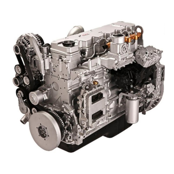
Page 5: Engine Technical Data N40 Ent M25
Injection type Direct/Common rail all liability on the part of IVECO MOTORS. electronically managed Engine direction of rotation Anticlockwise... - Page 6 04_363_N 04_364_N Engine NEF N40 ENT M25 Engine NEF N40 ENT M25 1. Coolant expansion tank - 2. Oil extraction pump - 3. Oil dipstick - 1. Exhaust gas and sea water discharge - 2. Turbocharger - 3. Engine 4. Oil filler cap - 5. Common rail divider - 6. Sea water pump inlet - coolant-sea water heat exchanger - 4.
-
Page 7: Engine Technical Data N60 Ent M37/M40
Electrical system 12 V (24 V on request) prohibited, penalty invalidation of the guarantee and absence of Accumulator/s all liability on the part of IVECO MOTORS. - capacity 180 Ah or above - discharge current 800 A or above... - Page 8 04_352_N 04_353_N Engine NEF N60 ENT M37/M40 Engine NEF N60 ENT M37/M40 1. Exhaust gas and sea water discharge - 2. Turbocharger - 3. Engine 1. Coolant expansion tank - 2. Oil extraction pump - 3. Oil filler cap - coolant-sea water heat exchanger - 4.
-
Page 9: Engine Technical Data N40 Ent M25
IVECO MOTORS. Engine direction of rotation Anticlockwise (seen from flywheel side) - Page 10 04_352_N 04_353_N Engine NEF N67 ENT M45 Engine NEF N67 ENT M45 1. Exhaust gas and sea water discharge - 2. Turbocharger - 3. Engine 1. Coolant expansion tank - 2. Oil extraction pump - 3. Oil filler cap - coolant-sea water heat exchanger - 4.
-
Page 11: Signs
SIGNS Certain warning signs are affixed to the engine, and their meanings are indicated below. NOTE: The signs with an exclamation mark on them underline a potential danger. Lifting point (engine only). Danger of burning: Expulsion of hot water under pressure. Fuel Cap Danger of burning: (on the fuel tank, if there is one). -
Page 12: Use
The start-up and shut-down operations described below apply to an on- Before starting the engine each time: board control panel manufactured by IVECO MOTORS; if the vessel is Make sure that the sea-water inlet valve is open. Operation of the... -
Page 13: Starting And Stopping The Engine From The Analogue Control Panel
STARTING AND STOPPING THE ENGINE FROM THE ANALOGUE CONTROL PANEL Procedure for start-up from the main IVECO MOTORS control panel (supplied on demand) Make sure that the electrical switch indicating ENGINE ROOM - BRIDGE on the Relay Box unit (normally located in the engine room) is in the BRIDGE position, then proceed as follows: 1. - Page 14 Procedure for start-up from IVECO MOTORS secondary or fly-bridge control panel (supplied on demand) 1. Enable the secondary control panel, by turning the key switch on the main panel to position 8B (see warnings and procedure given in previous paragraph).
-
Page 15: Stopping The Engine
A. The engine is normally stopped from the main IVECO MOTORS control panel by turning the key switch to the rest position 8A or by turning a similar command on the customised control panel. -
Page 16: Recognising Alarms
RECOGNISING ALARMS IVECO MOTORS on-board control panels with analogue instruments are fitted with an electronic module that includes the indicator lights and the interface, timer and alarm storage circuits. The figure illustrates the dial and the key indicates the meaning of the alarm signals sent by all the indicator lights;... -
Page 17: Starting And Stopping The Engine From The Digital Control Panel
STARTING AND STOPPING THE ENGINE FROM THE DIGITAL CONTROL PANEL Procedure for start-up from the main IVECO MOTORS control panel (supplied on demand) Make sure that the electrical switch indicating ENGINE ROOM - BRIDGE on the Relay Box unit (normally located in the engine room) is in the BRIDGE position, then proceed as follows: 1. - Page 18 Procedure for start-up from IVECO MOTORS secondary or fly-bridge control panel (supplied on demand) 1. Enable the secondary control panel, by turning the key switch on the main panel to position 8B (requirements and procedure given in previous paragraph). 2. Wait for the beeper to stop sounding and for the alarm indicator lights to switch off, with the exception of the “Alarm malfunction”...
-
Page 19: Recognising Alarms
If the Boatyard uses different technical A. From the main IVECO MOTORS control panel: turn the options there may also be changes to the above. - Page 20 Operation Detail of the main control panel When the key switch is turned to position 8B an efficiency test will be performed on all the indicator lights, lasting 5 seconds, with the exception of the “Pre-lubrication”, “Pre-post heating”, “EDC electronic injection system malfunction”...
- Page 21 If the set value does not correspond with the one foreseen for the type N40 ENT M25 of oil being used (see requirements in the sections on REFUELLING and Maximum power CV Maximum input mg/strk FREQUENCY) proceed as follows: - After displaying the value in hours set previously, release the buttons and press just the “Scroll select”...
-
Page 22: Managing The Engine From The Relay Box
MANAGING THE ENGINE FROM THE RELAY Start-up procedure 1. Turn switch 1 to the ENGINE ROOM position to enable the adjacent START-STOP button (2); this operation disables all The engine fittings include a unit, known as the “Relay box” and normally the on-board control panel functions on the bridge and installed in the engine room, using which it is possible to manage the fly-bridge. -
Page 23: Proper Use Of The Engine
FOR PROPER USE OF THE ENGINE SPECIAL WARNINGS Do not continue to press the starter, when the engine has started. Coolant temperature high Do not remain in dock while waiting for the engine to warm up, If the temperature indicated on the instrument is considered too high, but after starting, commence navigation at low speed;... -
Page 24: Running In
Water in the fuel pre-filter Alternator malfunction It is a good rule to drain the water from the filters, before the relevant Check it or have it checked periodically for cleanliness, wear and proper indicator comes on. tensioning of the drive belt. Avoid using the engine with the fuel tank only a small reserve of fuel;... -
Page 25: Refuelling
REFUELLING Oil consumption is considered acceptable when it reaches a maximum of 0.5% of fuel consumption. Parts to be supplied N40 ENT N60 ENT (3)The amounts indicated refer to initial refuelling, and include filling litres (kg) litres (kg) the engine, sump and filter. (4)Only use normal commercial diesel fuel (EN 590 standards). -
Page 26: Controls And Maintenance
Do not leave foreign bodies on the engine. by the key symbol (see illustration). Use suitable, safe containers for used oil. The Authorised Service Centres are the ones in the IVECO MOTORS When completing a repair, make suitable provisions to stop the Technical Service Network. -
Page 27: Frequency
CAUTION! Planned maintenance Frequency Do not carry out maintenance operations when the electric power supply is turned on: always check to ensure (2) (7) Clean air filter/s 300 hours that the appliances are properly earthed. During diagnosis (4) (7) Check corrosion of zinc anodes 300 hours and maintenance operations, make sure that your hands and feet are dry, and whenever possible use insulating... - Page 28 5) Replace lubricants according to the frequency indicated in the REFUELLING table. Special maintenance Frequency 6) Sea water/combustion air heat exchanger: clean both the air and water sections; engine coolant/sea water heat exchanger: clean the sea water section; optional sea water/marine gear oil heat Check wear in sea water pump rotor 900 hours exchanger: clean the sea water section.
-
Page 29: Requirements
HOW TO PROCEED REQUIREMENTS 1. Do not disconnect the batteries with the engine running. Check oil level in engine 2. Do not carry out arc welding operations in the vicinity of the engine Only proceed with the engine stopped and at a low temperature, so as without first removing electrical cables and electronic units. - Page 30 Check oil level in marine gear Draining water from the fuel pre-filter Check the oil level in the marine gear following the indications provided The high risk of refuelling with fuel that is polluted by foreign bodies and in the marine gear Manufacturer's manual. water means that it is necessary to perform this control even if no alarm is shown on the on-board control panel.
- Page 31 Contact specialised technical staff if the battery needs recharging. Cleaning the air filter Have the efficiency of the battery recharging system tested if a Remove the filter by loosening the screws (4) indicated in the voltage of less than 11 V (for 12 V rated systems) or 22 V (for figure.
- Page 32 Check corrosion of zinc anodes Unscrew the filler cap, turn the hand pump provided (2), which is set up to extract the oil only, until the oil sump is completely empty. Only proceed with the engine stopped and at a low temperature: Fill up with fresh oil through the feeder hole (3) on the timer cover, Provide suitable containers to ensure that no water is dispersed using the types and amounts of oil indicated in the table...
- Page 33 Changing the fuel filter Only proceed with the engine stopped and at a low temperature Remove the filter by unscrewing it. Check that the new filter has performance levels that satisfy the needs of the engine (e.g. by comparing them with the old one. See section on FREQUENCY).
- Page 34 Changing the fuel pre-filter Check tension and state of the auxiliary member drive belt Only proceed with the engine stopped and at a low temperature Only proceed with the engine stopped and at a low temperature, so as Remove pre-filter to avoid the risk of burning.
- Page 35 The operations listed below must only be carried out by qualified Remove the plugs on the circuit components and wait until the staff from the IVECO MOTORS Service Centres or by staff from the circuit has drained completely (the location of plugs is given in the Boatbuilders.
-
Page 36: Moving The Engine
MOVING THE ENGINE DISPOSAL OF WASTE The operations necessary to embark and disembark the engine must The engine is made up of parts and elements that, if discarded, may only be carried out by technicians from Authorised Service Centres. cause damage to the environment. When lifting the engine only, use the U-bolts indicated in this manual The materials listed below must be handed over to specialised in the section ENGINE TECHNICAL DATA and marked on the engine... -
Page 37: Long Periods Of Inactivity
LONG PERIODS OF INACTIVITY 7. Drain the residual 30/M protective oil from the sump. This oil can be used again for a further 2 preparation operations. 8. Fit signs reading ENGINE WITHOUT OIL to the engine and to the PREPARING THE ENGINE FOR A LONG on-board control panel. -
Page 38: Restarting The Engine After A Long Period Of Inactivity
RESTARTING THE ENGINE AFTER A LONG PERIOD OF INACTIVITY 1. Drain the residual 30/M protective oil from the sump. 2. Fill the engine, as prescribed, with lubricant of the type and amount indicated in the table REFUELLING. 3. Drain the CFB protective fluid from the fuel circuit, carrying out this operation as indicated under point 3. -
Page 39: Engine Malfunctions
ENGINE MALFUNCTIONS CAUTION! The electronic unit overseeing management and control of all operation of the engine is capable of recognising any malfunctions that may occur, The engine electronic control unit can adopt safety and of adopting strategies that will allow you to navigate in full safety. strategies at any time during navigation, should The event, signalled by light-up of the EDC MALFUNCTION indicator conditions arise that are considered to put the engine... -
Page 40: Emergencies On Board
EMERGENCIES ON BOARD Burns and scalds 1. Extinguish any flames on the burned person's clothing, by: The user of a vessel that has been constructed according to safety • throwing water over them; regulations, when following the instructions provided in this manual and •... - Page 41 Electrocution Caustic burns The engine's electrical 12 V or 24 V electrical system does not involve Caustic skin burns are caused by contact with extremely acid or alkaline the risk of electrocution, however, in the event of a short-circuit caused, substances.
Need help?
Do you have a question about the N40 ENT M25 and is the answer not in the manual?
Questions and answers