Table of Contents
Advertisement
Quick Links
Advertisement
Table of Contents
Troubleshooting

Related Manuals for Ricoh B286


Summary of Contents for Ricoh B286
- Page 1 B286/B289 SERVICE MANUAL 003165MIU...
- Page 5 B286/B289 SERVICE MANUAL 003165MIU...
- Page 7 It is the reader's responsibility when discussing the information contained within this document to maintain a level of confidentiality that is in the best interest of Ricoh Americas Corporation and its member companies. NO PART OF THIS DOCUMENT MAY BE REPRODUCED IN ANY FASHION AND DISTRIBUTED WITHOUT THE PRIOR PERMISSION OF RICOH AMERICAS CORPORATION.
- Page 9 Ricoh Technical Training Program. Untrained uncertified users utilizing information contained in this service manual to repair or modify Ricoh equipment risk personal injury, damage to property or loss of warranty protection. Ricoh Americas Corporation...
- Page 11 LEGEND PRODUCT CODE COMPANY Gestetner LANIER RICOH SAVIN B286 GWD2004 LW324 MPW2400 2404WD B289 GWD2006 LW336 MPW3600 2406WD DOCUMENTATION HISTORY REV. NO. DATE COMMENTS 07/2007 Original Printing...
-
Page 13: Table Of Contents
1.1.5 INSTALLATION OVERVIEW ............1-3 Installation Flow..................1-3 SP and User Tool Settings Required for Installation ......1-4 1.2 MAIN MACHINE INSTALLATION (B286) ..........1-7 1.2.1 ACCESSORY CHECK ..............1-7 1.2.2 MACHINE INSTALLATION PROCEDURE ........1-8 Removing the Shipping Material............1-8 Set the Operation Panel Position ............ - Page 14 Attaching the Stopper Brackets ............1-54 Table Accessories ................1-54 1.7 INSTALLATION OF MFP OPTIONS ............1-56 1.7.1 OVERVIEW..................1-56 1.7.2 ENABLING THE ONBOARD FEATURES........1-57 1.7.3 USING SD CARDS ................. 1-58 Removing the SD Card Slot Cover............. 1-58 B286/B289...
- Page 15 Accessories ..................1-72 Before You Begin…................1-72 Seal Check and Removal ..............1-72 Installation ..................1-72 Check Operation of the DOS Application ........... 1-74 1.7.11 USB HOST INTERFACE UNIT TYPE 7300 (G819-01) ..1-75 Accessories ..................1-75 Installation ..................1-75 B286/B289...
- Page 16 1.8.2 INSTALLATION ................1-80 PREVENTIVE MAINTENANCE 2. PREVENTIVE MAINTENANCE ........... 2-1 2.1 PM TABLE ....................2-1 2.1.1 MAIN MACHINE (B286)..............2-1 2.1.2 ROLL FEEDER (B851/B852) ............2-4 2.1.3 PAPER CASSETTE (B853) .............. 2-5 2.1.4 FOLDER FD/MANUAL FEEDER (D889) .......... 2-5 2.1.5 MANUAL FEEDER (D333)..............
- Page 17 3.3.3 LPH (LED PRINT HEAD) ..............3-18 3.3.4 TRANSFER CORONA, SEPARATION CORONA WIRES....3-19 3.4 DEVELOPMENT ..................3-21 3.4.1 DEVELOPMENT UNIT ..............3-21 3.4.2 DEVELOPER .................. 3-22 3.4.3 PAPER SET SENSOR, REGISTRATION SENSOR ....... 3-24 3.4.4 TONER SUPPLY CLUTCH............. 3-25 3.4.5 DEVELOPMENT FILTER..............3-25 B286/B289...
- Page 18 HOT ROLLER ................3-48 3.7.11 PRESSURE ROLLER ............... 3-48 3.7.12 HOT ROLLER THERMISTOR, THERMOSTATS...... 3-49 3.8 MOTORS ....................3-50 3.8.1 SCANNER MOTOR ................ 3-50 3.8.2 DRUM MOTOR................3-51 3.8.3 FUSING MOTOR, MAIN MOTOR........... 3-51 3.8.4 USED TONER BOTTLE MOTOR ........... 3-53 B286/B289...
- Page 19 Doing SP Adjustment Settings for a Replacement LPH ..... 3-80 To Print Pattern IPU Test Pattern 10..........3-81 Main Scan Adjustment: White, Black Vertical Lines ......3-82 Main Scan Adjustment: LED Light Level at LPH Joints ...... 3-83 Adjusting LPH Alignment..............3-83 B286/B289...
- Page 20 4.3.4 FOLDER UNIT JAMS ..............4-33 Folder Unit Standby Jams ..............4-33 Folder Unit Late Jams ................ 4-34 Folder Unit Lag Jams ................. 4-35 4.4 COVER OPEN ..................4-36 4.5 FUSES ..................... 4-37 4.6 IMAGE PROBLEM TROUBLESHOOTING ..........4-38 B286/B289 viii...
- Page 21 5.3 USER TOOLS .................... 5-6 5.3.1 USER TOOL SUMMARY ..............5-6 System Settings ................... 5-6 Copier/Document Server Features............5-9 Espanol ....................5-12 Inquiry ....................5-12 Counter ....................5-12 5.4 INPUT CHECK..................5-13 5.5 OUTPUT CHECK..................5-19 5.6 SP TABLE KEY..................5-21 B286/B289...
- Page 22 CIS Structure..................6-12 Printed Image ..................6-13 6.2.7 AUTO IMAGE DENSITY CORRECTION ........6-13 6.3 IMAGE PROCESSING................6-15 6.3.1 GENERAL IMAGE PROCESSING FLOWCHART......6-15 6.3.2 ORIGINAL MODES................. 6-16 Overview .................... 6-16 Drawing Mode ..................6-17 Text Mode ..................6-18 B286/B289...
- Page 23 Fixed Supply Mode................6-41 Toner Supply Clutch Operation ............6-41 6.6.9 TONER END/NEAR-END DETECTION.......... 6-43 Toner Near End.................. 6-43 Toner End................... 6-43 Toner End Recovery ................6-43 6.7 PAPER FEED AND REGISTRATION ............6-45 6.7.1 OVERVIEW..................6-45 Layout Diagrams ................6-45 B286/B289...
- Page 24 6.9.4 HOT ROLLER THERMISTORS AND THERMOSTATS ....6-69 6.9.5 TEMPERATURE CONTROL ............6-69 Paper Thickness Setting ..............6-69 Zero-Cross Control Test ..............6-71 Switching on the Fusing Lamp Power ..........6-71 Fusing Temperature Control: Warm-up Sequence......6-72 Fusing Temperature Control: Temperature Feedback During Copying6-74 B286/B289...
- Page 25 VDB (Video Drive Board) ..............6-102 SIB (Scanner Interface Board) ............6-102 CIS I/F (1 to 5).................. 6-102 6.11.6 RFDB, SFDB ................6-103 RFDB (Roll Feed Drive Board) ............6-103 SFDB (Sheet Feed Drive Board) ............6-103 6.11.7 GW CONTROLLER BOARD ........... 6-104 xiii B286/B289...
- Page 26 SPECIFICATIONS 7. SPECIFICATIONS................ 7-1 7.1 MAIN MACHINE (B286/B289) ..............7-1 7.2 OPTIONS....................7-6 7.2.1 ROLL FEEDER B851/B852 .............. 7-6 7.2.2 FOLDER (D889) ................7-7 7.2.3 MANUAL FEEDER D333 ..............7-8 7.2.4 PAPER CASSETTE B853..............7-9 7.3 MAIN MACHINE CONFIGURATION............7-10...
-
Page 28: Replacement And Adjustment
INSTALLATION PREVENTIVE MAINTENANCE REPLACEMENT AND ADJUSTMENT TROUBLESHOOTING SERVICE TABLES DETAILED DESCRIPTIONS SPECIFICATIONS... - Page 30 Read This First Safety, Conventions, Trademarks Safety PREVENTION OF PHYSICAL INJURY Before disassembling or assembling parts of the machine and peripherals, make sure that they are unplugged. The plug should be near the machine and easily accessible. Note that some components of the machine and the paper tray unit are supplied with electrical voltage even if the main power switch is turned off.
- Page 31 Dispose of replaced parts in accordance with local regulations. When keeping used lithium batteries in order to dispose of them later, do not put more than 100 batteries per sealed box. Storing larger numbers or not sealing them apart may lead to chemical reactions and heat build-up. The danger of explosion exists if a battery of this type is incorrectly replaced.
- Page 32 In this manual “Horizontal” means the “Main Scan Direction” and “Vertical” means the “Sub Scan Direction” relative to the paper feed direction. Warnings, Cautions, Notes In this manual, the following important symbols and notations are used. A Warning indicates a potentially hazardous situation. Failure to obey a Warning could result in death or serious injury.
- Page 33 Other product names used herein are for identification purposes only and may be trademarks of their respective companies. We disclaim any and all rights involved with those marks.
-
Page 35: Installation
INSTALLATION... -
Page 37: Preparation
The machine will not be directly exposed to reflected heat from a space heater in the winter. Do not install the machine in an area filled with gases that can cause corrosion. Do not install the machine in areas higher than 2,000 m (6,600 ft) above sea level. B286/B289... -
Page 38: Minimum Space Requirements
This machine is provided with a circuit breaker that cuts the power supply to the main machine in case of a current overload or short circuit. The machine must be installed in a building where circuit breakers (and equivalent devices) can operate properly. Input Voltage Level: 120V, 60 Hz, 15 A or more B286/B289... -
Page 39: Installation Overview
SP and User Tool Settings for Installation Do all the SP and User Tool settings for the copier and the installed options. Copier Final Installation Complete the installation of the copier after you put it on the roll feeder or table, and after B286/B289... -
Page 40: Sp And User Tool Settings Required For Installation
Initializes the ID sensor after toner has Initialization been applied to the drum. User Tool System Settings> Tray Paper Sets the paper size for each tray: Settings> Tray Paper Size: Tray 1: Roll 1 Tray n Tray 2: Roll 2 Tray 3: Cassette Bypass B286/B289... - Page 41 Adjust for B852, 2 Roll Roll:1189 mm:Plain Paper 1001-1 Leading Edge Registration – Adjust B851/B852, 1 roll. Roll 1001-2 Leading Edge Registration – Adjust for B852, 2 roll. Roll 1002-1 Side-to-Side Registration – 1 Adjust for B851/B852, 1 roll Roll B286/B289...
- Page 42 Adjust for Paper Cassette B853. Cassette 1002-3 Side-to-Side Registration – Cassette MFP Options 5985-1 Device Setting – On Board NIC Both SP codes must be set to “1” to enable these features. 5985-2 Device Setting – On Board USB B286/B289...
-
Page 43: Main Machine Installation (B286)
Main Machine Installation (B286) 1.2 MAIN MACHINE INSTALLATION (B286) Always have this Service Manual with you. The installation procedures are not shipped with the main machine. Never turn the main machine off when the main power LED is lit or flashing. To... -
Page 44: Machine Installation Procedure
Main Machine Installation (B286) 1.2.2 MACHINE INSTALLATION PROCEDURE Removing the Shipping Material Do not connect the power cord to the power source during these installation procedures until the procedure tells you to do this. Remove all the orange filament tape and packing materials from the main machine (front and back). -
Page 45: Set The Operation Panel Position
Main Machine Installation (B286) Set the Operation Panel Position You can adjust the position of the operation panel to decrease bright reflections from the operation panel display.. Lift or lower the operation panel [1] to one set of the three sets of holes to set the panel at the desired angle. - Page 46 Main Machine Installation (B286) The main machine weighs 107 kg (235 lb.). There are two handles in recesses on each side of the main machine. To prevent injury or damage to the main machine, always use these handles [3] to lift the main machine.
- Page 47 Main Machine Installation (B286) Open the upper unit. Remove: [1] Left cover (" x 3) [2] Right cover (" x 3) [3] Manual feed table (" x 2). Open the drawer of the roll feeder before removing if the roll feeder is installed.
- Page 48 Main Machine Installation (B286) 10. Install the studs [1] on the right side and the left side. You must fasten each stud in the upper hole [2] on both sides. 11. Attach the right joint bracket [1] (the spindle [2] must go through the hole). At the same time, align the plate with the holes for the three screws (blue).
- Page 49 Main Machine Installation (B286) 15. Do the above procedure again for the left joint bracket [4]. The guide plate and screws are provided as accessories with either the Roll Feeder (B851/B852) or Table (B854). 16. Install the guide plate [1] (" x 2 Blue). Hang the hooks on each end; this puts the plate in the correct position to be installed.
-
Page 50: Leveling The Main Machine And Attaching Leg Covers
Main Machine Installation (B286) into the holes. 18. Lift each plate and let it fall, to make sure that they move smoothly on the hinges. 19. Reattach the manual feed table. 20. Reattach the left and right covers. The flat-head screw must be attached at the rear side of each cover. - Page 51 Main Machine Installation (B286) Use a wrench to adjust the nuts [1] on each foot to raise or lower the main machine at each corner. The main machine must be level side-to-side within ±0.15/m. Attach the left leg cover [2] and the right leg cover [3].
-
Page 52: Developer
Main Machine Installation (B286) 11. Reattach the hinges and fasten the lock screws removed in Step 8. Developer Push up the buttons [1] to release the upper unit. Then open the upper unit [2]. Open the toner hopper cover [3]. -
Page 53: Toner Cartridge Installation
Main Machine Installation (B286) Open a 1 kg pack of developer and pour it into the development unit. Do not add the second pack at this time. Open the first pack of developer [1]. Slowly add the developer from the first pack into the development unit, as you move the pack from left to right until the pack is empty. - Page 54 Main Machine Installation (B286) Remove the cartridge from its package. Gently tap the capped end of the cartridge [1] 4 or 5 times. Tap the other end of the cartridge 4 or 5 times. Shake the cartridge from side to side 4 or 5 times so the toner moves freely inside the cartridge.
-
Page 55: Enter Developer Lot Numbers
Main Machine Installation (B286) To install a toner cartridge Set the toner cartridge [1] in the main machine. Pull up the tape [2] then pull it across the toner cartridge from right to left to remove the tape. On the right end of the toner cartridge, push the knob [3] up until it stops. - Page 56 Main Machine Installation (B286) Open the upper unit. Push the cleaning-blade release lever [1] to the right. The cleaning-blade release lever keeps the cleaning blade away from the drum during transportation. To prevent damage to the drum, before you move the main machine to a different location, be sure to push this lever to the left.
-
Page 57: Main Machine Final Installation
Main Machine Installation (B286) 1.2.3 MAIN MACHINE FINAL INSTALLATION Select the Tray Paper Size and Type Push [User Tools] > “System Settings” > “Tray Paper Settings.” Selections are shown only for installed options. If you installed all the options, you will see “Tray Paper Size: Tray 1” (1 Roll), “Tray Paper Size: Tray 2”... -
Page 58: Main Machine Accessories
Main Machine Installation (B286) Push the breaker lever to display “|” again and reset the main machine for normal operation. The main machine power will not turn on if the switch [2] remains at “O.” Reattach the rear cover. Main Machine Accessories... -
Page 59: Roll Feeder, Table Accessories
Main Machine Installation (B286) Keep the copy-exit selection lever at the vertical position for normal operation. When the lever is up, the user can push the “Upper Copy Output” key to feed copies out of the main machine at the top or straight-through out the rear. - Page 60 Main Machine Installation (B286) The lines and numbers embossed on the back of the main machine (see the upper left of the above diagrams) show where to position the exit guide plates for different paper widths. Position the right exit guide plate [1] as shown, then attach it with its magnet.
-
Page 61: Copy Check
Main Machine Installation (B286) Copy Check Scan an original to confirm that the main machine operates correctly. Set an original or test pattern face down on the original feed tray. After about 1 second, the main machine pulls the original, stops for 1 second, then starts to feed it. - Page 62 Main Machine Installation (B286) and push the cleaning blade lever to the left. This keeps the cleaning blade away from the drum while you move the main machine. If you will move the main machine to a different location in the same building, it is not necessary to set the lever to the left, and it is not necessary to disconnect the main machine from the roll feeder or table.
-
Page 63: Original Hanger (D311)
Check the accessories and their quantities against the table below. Description Q’ty Original Hangers 1.3.2 INSTALLATION Attach one original hanger [1] to the bypass feed table [2]. Attach the other original hanger [3] to the bypass feed table. 1-27 B286/B289... - Page 64 Lower Output Trays Leg Covers Movable Guides Shoes Joint Brackets (Left, Right) Exit Guide Plates Screws (Cosmetic Silver) Screws (Blue) Harness Brackets Mylars – Wide Mylars – Narrow Nylon clamp Harness clamp Ferrite Core (for B275) Guide Plate B286/B289 1-28...
-
Page 65: Roll Feeder (B851/B852)
There are two handles in recesses on each side of the main machine. To prevent injury or damage to the main machine, always use these handles [3] to lift the main machine. Two or more service technicians are necessary to lift the main machine and 1-29 B286/B289... -
Page 66: Opening The Roll Feeder And Removing Shipping Material
Remove the roll paper holders [3] and cardboard packing [4]. Roll Feeder B851 has 2 holders, and Roll Feeder B852 has 4 holders (shown above). Remove other tape or packing material in the roll feeder. Remove the shipping lock plate [5] (" x 2). B286/B289 1-30... - Page 67 [2] Left screws (" x 2) [3] Right upper cover (" x 2) [4] Right screws (" x 2) Open the upper unit. Remove: [1] Left cover (" x 3) [2] Right cover (" x 3) [3] Manual feed table (" x 2). 1-31 B286/B289...
- Page 68 Remove the right transport lock plate [1] (" x 4). 10. Remove the left transport lock plate [2] (" x 4). 11. Install the studs [1] on the right side and the left side. You must fasten each stud in the upper hole [2] on both sides. B286/B289 1-32...
- Page 69 15. Tighten screws 16. Do the above procedure again for the left joint bracket [4]. The guide plate and screws are provided as accessories with the roll feeder. 1-33 B286/B289...
- Page 70 19. Lift each plate and let it fall, to make sure that they move smoothly on the hinges. 20. Reattach the manual feed table. 21. Reattach the left and right covers. The flat-head screw must be attached at the rear side of each cover. 22. Close the upper unit. B286/B289 1-34...
-
Page 71: Leveling The Main Machine And Attaching Leg Covers
Use a wrench to adjust the nuts [1] on each foot to raise or lower the main machine at each corner. The main machine must be level side-to-side within ±0.15/m. Attach the left leg cover [2] and the right leg cover [3]. 1-35 B286/B289... - Page 72 11. Use a wrench to adjust the nuts on each foot to lift or lower the main machine at each corner. The main machine must be level side-to-side within ±0.15/m. 12. Reattach the hinges and fasten the lock screws removed in Step 8. B286/B289 1-36...
-
Page 73: Connecting The Main Machine And Roll Feeder
Remove the cover of the controller unit [2] ("x1). Remove the ground plate [1] (" x 3). Open the paper exit cover (C1) and paper exit unit (C2) together to remove screw (the vertical screw). Remove the shield cover [2] (" x 8). 1-37 B286/B289... - Page 74 (Use one screw from the accessories). 10. Connect the left harness [1] to CN103 on the PSU (# x 1, & x 1). 11. Connect the right harness [2] to CN220 and CN221 on the MCU (# x 2, & x 3). B286/B289 1-38...
- Page 75 Open and close the paper exit cover C1 and paper exit unit C2 together to confirm that the rear cover is installed correctly. If the paper exit cover does not open properly, remove the rear cover and install it again. 1-39 B286/B289...
-
Page 76: Attaching The Narrow Mylars To The Main Machine
Attach the other end of the mylar to the bottom edge of the cover Do this procedure again to attach the other narrow mylar to the right side of the cover. B286/B289 1-40... -
Page 77: Attaching The Wide Mylars To The Back Of The Roll Feeder
“L” pattern embossed on the plate, then push it against the rear plate. Make sure that the tape surfaces are pushed fully against the rear plate. Reattach the rear cover of the main machine (" x 2). 1-41 B286/B289... -
Page 78: Securing The Power Cord
If you do not install the paper cassette first, you must remove Roll 2 before you can install the optional paper cassette. To install the paper rolls, follow the instructions on the decal on the top edge of the roll feeder drawer. B286/B289 1-42... -
Page 79: Attaching The Lower Output Tray, Exit Guide Plates
Position the right exit guide plate [1] as shown then attach it with its magnet. Position the left exit guide plate [2] as shown then attach it with its magnet. 1-43 B286/B289... -
Page 80: Entering The Cut Length Adjustment
Push [User Tools]> “System Settings”> “Tray Paper Settings”> “Tray Paper Size: Tray 1”, “Tray Paper Size: Tray 2.” Select the paper size for Tray 1 and Tray 2. Push “Next”> “Paper Type: Tray 1”, “Paper Type: Tray2 Select the paper type for Tray 1 and Tray 2. B286/B289 1-44... -
Page 81: Paper Cassette (B853)
Q’ty Paper Cassette Unit Screws Harness Clamps Paper Cassette (Universal Type) 1.5.2 PAPER CASSETTE INSTALLATION PROCEDURE Confirm that the machine is switched off and that the power cord is disconnected from the power source before doing this procedure. 1-45 B286/B289... - Page 82 Remove the rear plate of the roll feeder (" x 2). Put the cassette unit [1] in the roll feeder. The bosses must go through the holes in the flanges of the cassette unit. Then, attach the cassette unit (" x 4). B286/B289 1-46...
- Page 83 Push [User Tools]> “System Settings”> “Tray Paper Settings”> “Tray Paper Size: Tray 3” Select the paper size for the paper cassette.. Push “Next”> “Paper Type: Tray 3” Select the paper type for the paper cassette. (Default: Plain Paper). 1-47 B286/B289...
-
Page 84: Accessory Check
Check the accessories and their quantities the table below. Description Q’ty Lower Output Trays Leg Covers Shoes Joint Brackets (Left, Right) Exit Guide Plates Screws Mylars – Wide Mylars – Narrow Guide Plate Nylon Clamp Harness Clamp Stopper Bracket (for inch paper sizes) B286/B289 1-48... -
Page 85: Installation Procedure
With one person at each end of the main machine, use the two handles on each end of the main machine to lift it. Make sure that you put the rubber feet of the main machine into the holes on top of the table. 1-49 B286/B289... -
Page 86: Leveling The Main Machine And Attaching Leg Covers
Keep the power cord disconnected while you do this procedure. Install the guide plate [1] (" x 2 Blue). Hang the hooks on each ends; this puts the plate in the correct position to be installed. Connecting the Main Machine and Table B286/B289 1-50... - Page 87 Make sure that you attach the longer screws with the fine threads at the rear sides of the covers. Close the upper unit. Clean the rear plate [1] of the table with alcohol. 10. Attach the harness clamp [2]. 11. Clamp the power cord [3] to the table (" x 1). 1-51 B286/B289...
-
Page 88: Attach The Narrow Mylars To The Main Machine
Attach the other end of the mylar to the bottom edge of the cover Do this procedure again to attach the other narrow mylar to the right side of the cover. Reattach the cover to the back of the main machine (" x 2). B286/B289 1-52... -
Page 89: Attach The Wide Mylars To The Back Of The Table
Turn the end with the wide tape against the plate, and align its corner [5] with the inverted “L” pattern embossed on the plate , then push it against the rear plate. Make sure that the tape surfaces are pushed fully against the rear plate. 1-53 B286/B289... -
Page 90: Attaching The Stopper Brackets
Use a clean cloth soaked in alcohol to clean the surfaces [2] where the stopper brackets [3] will be attached. Remove the double-sided tape [4] from the rear of each bracket. Install each bracket and stopper on the arms. Lock each stopper in the correct position (% x 2 each). Table Accessories B286/B289 1-54... - Page 91 Position the right exit guide plate [1] as shown then attach it with its magnet. Position the left exit guide plate [2] as shown then attach it with its magnet. Do a test print to confirm that the paper exits the main machine straightly and smoothly between the guide plates. 1-55 B286/B289...
-
Page 92: Installation Of Mfp Options
MFP Option Board Slot/SD Card Assignments Slot Option Name Move? Interface PCB Type W3600 (D329) Gigabit Ethernet Board Type A (G874-01) IEEE 802.11b Interface Type H (G813-45)/Type I (G874-39) USB Host Interface Unit Type 7300 (G819-01) File Format Converter Type C (B609-04) B286/B289 1-56... -
Page 93: Enabling The Onboard Features
The NIB and USB support features are built into the GW controller board. However, these features cannot be used until they have been enabled with SP5985 (Device Setting). Before installing any other options in this section, do SP5985 and make sure each item is set to “1.” 1-57 B286/B289... -
Page 94: Using Sd Cards
If the service technician needs to use Slot 3 for servicing and there is an SD card in Slot 3, the application SD card must be removed. If the customer needs more than three applications, one or more application must be moved to one SD card with SP5873-1. B286/B289 1-58... -
Page 95: Restrictions And Precautions On The Use Of Sd Cards
It is very easy to accidentally turn on the write-protect switch when inserting and removing an SD card. To remove an SD card from its slot, push it in gently to release it then pull it out of its slot. 1-59 B286/B289... -
Page 96: Application Move
14. Tell the customer to store the original SD card in a safe place. Undo Exec “Undo Exec” (SP5873-2) restores an application to its original SD card. The application is moved from Slot 3 to Slot 1 (or Slot 2). B286/B289 1-60... -
Page 97: Printer Option Type W3600 (D320)
1.7.4 PRINTER OPTION TYPE W3600 (D320) The Roll Feeder (B851/B852) is required in order to use the Printer Option (D320). Accessories Check the accessories and their quantities against the table below. Description Qt’y SD Card: Printer SD Card: TIFF/GL Filter 1-61 B286/B289... -
Page 98: Installation
12. Print a Configuration Page to make sure that the machine recognizes the installed board: User Tools> Printer Features> List/Test Print> Configuration Page 13. Contact the system administrator then do the network settings in the User Tools mode B286/B289 1-62... -
Page 99: Scanner Option Type W3600 (D321)
If the printer SD card is in Slot 1, do SP5873-1 to move the scanner application to the printer application SD card. Reattach the SD card slot cover ("x1). On the operation panel, remove the dummy keytop and replace it with the “Scanner” keytop. 1-63 B286/B289... -
Page 100: Accessories
Before doing the procedure, turn off the main power switch and unplug the machine from its power source. Make sure that the machine is switched off and disconnected from its power source. If the folder unit is installed, disconnect it and pull it away from the main machine. B286/B289 1-64... - Page 101 Installation of MFP Options Remove: [A] Rear cover ("x2) [B] Controller cover ("x1) Remove: [A] Ground plate ("x3) Open covers C1 and C2 together to remove the vertical screw. [B] PCB shield cover ("x8) 1-65 B286/B289...
- Page 102 Remove cover [1] and discard it ("x2). Keep the screws. Attach the bracket [2] removed in Step 5 to the PCB ("x2). Disconnect the connectors [1] (#x3). Slowly insert the board [2] then fasten it ("x2). Reinstallation Be sure to reconnect the connectors (#x3). B286/B289 1-66...
-
Page 103: Accessories
Nylon Clamp Harness Clamp Screws (M4x8) Installation Before doing the procedure, turn off the main power switch and unplug the machine from its power source. Make sure that the machine is switched off and disconnected from its power source. 1-67 B286/B289... - Page 104 Attach the interface cable to the back of the main unit [1] (Cable hooks x2) Clean the rear plate [2] with alcohol. Attach harness clamp [3]. Close the clamp round the harness cable [4]. Connect the other end of the interface cable to the server PC (Printer Controller RW3600). B286/B289 1-68...
-
Page 105: Accessories
Insert the wireless LAN card [3] into the adapter board [2]. Attach the cap [4]. Reconnect the machine to the power source and turn the main power switch on. Print a Configuration Page to confirm correct installation: User Tools> Printer Features> List/Test Print> Configuration Page 1-69 B286/B289... -
Page 106: Accessories
Touch a metal surface to discharge any static electricity from your hands before you handle the board. Installation Before doing the procedure, turn off the main power switch and unplug the machine from its power source. Make sure that the machine is switched off and disconnected from its power source. B286/B289 1-70... - Page 107 Attach both cores 4.5 cm (about 2 in.) from each end of the cord. Reconnect the machine to its power source and turn the main power switch on. Do SP5985-2 and set to “1” to enable the NIC and USB functions. 1-71 B286/B289...
-
Page 108: Accessories
If this setting is “Off”, tell the customer that this setting must be “On” before you can do the installation procedure. Make sure that “Administrator Tools” is selected and enabled: [User Tools] > “System Settings” > “Administrator Tools”> “Administrator Authentication Management”> “Available Settings B286/B289 1-72... -
Page 109: Seal Check And Removal
Make sure that the machine is switched off and disconnected from its power source. Disconnect the network cable. Turn the main power switch on. Turn the operation switch and main power switch off. 1-73 B286/B289... -
Page 110: Check Operation Of The Dos Application
If this occurs: Obtain the correct SD card. Replace the NVRAM on the controller board. Insert the Type D DOS unit SD card in Slot 1 Do the DOS unit installation procedure again. Check Operation of the DOS Application B286/B289 1-74... -
Page 111: Usb Host Interface Unit Type 7300 (G819-01)
Insert the board [2] into Slot C (Knob " x 2). Reconnect the machine to its power source and turn the main power switch on. Print a Configuration Page to make sure that the machine recognizes the installed 1-75 B286/B289... -
Page 112: Accessories
12. Under “Install to:” touch [Machine HDD] then touch [Next] 13. When you see “Ready to Install”, check the information on the screen to confirm the previous selection. 14. Touch [OK]. You will see “Installing…” then “Completed.” 15. Touch [Exit] twice to return to the copy screen. B286/B289 1-76... -
Page 113: Accessories
VM Card Decal Installation Before doing the procedure, turn off the main power switch and unplug the machine from its power source. Remove SD card slot cover ("x1). Insert the SD card into SD card slot 2 or 3. 1-77 B286/B289... - Page 114 If you push in the SD Card, this releases it for removal. Make sure that the SD Card is inserted and locked in place. If it is partially out of the slot, push it in gently until it locks. Switch the machine on. Attach the decal. B286/B289 1-78...
-
Page 115: Accessories
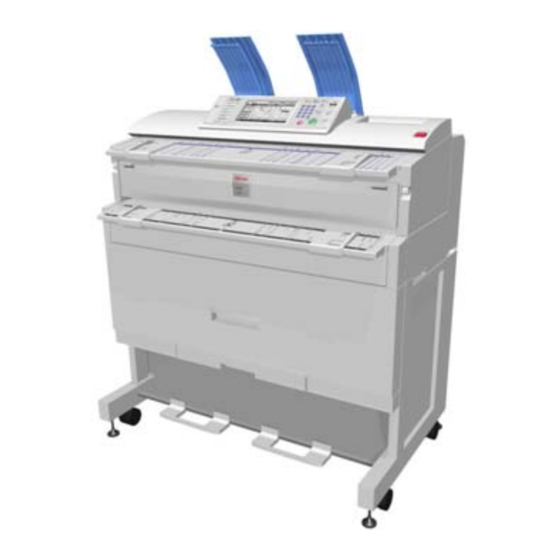
Rear Stacker (D312) 1.8 REAR STACKER (D312) The rear stacker is an optional device installed on the back of the unit (B286/B289). 1.8.1 ACCESSORIES Check the accessories and their quantities against the table below. Description Copy Tray Holder Guide Mylar... -
Page 116: Installation
Rear Stacker (D312) 1.8.2 INSTALLATION Attach: [1] Copy tray holder ("x4) [2] Rear copy tray (x3) [3] Guide mylar (x1) ) to center of copy tray B286/B289 1-80... -
Page 117: Preventive Maintenance
PREVENTIVE MAINTENANCE... -
Page 119: Pm Table
Key for the PM Table A = Adjust, C = Clean, I = Inspect, L = Lubricate, R = Replace Units of measure in the PM Interval column: Metric: 1,000 meters, Feet: 1,000 feet 2.1.1 MAIN MACHINE (B286) PM Interval Description Q’ty... - Page 120 36.0 T&S Unit Casing and 18.0 Lens paper or dry cloth. Guides Quenching Lamp 18.0 Lens paper or dry cloth ID Sensor 18.0 Dry cloth; do SP3001 2 to initialize the sensor after Pick-off Pawl 18.0 you clean it. B286/B289...
- Page 121 Fusing Exit Guide Plate 18.0 Paper Junction Gate 18.0 Fusing Entrance Guide 18.0 Cleaner brush Spurs Alcohol, dry cloth at every visit. (See section 2.2 “Cleaning the Entrance Spurs”) Fusing Exit Rollers 11.0 36.0 Damp cloth Fusing Exit Sensor 18.0 Blower brush B286/B289...
-
Page 122: Roll Feeder (B851/B852)
Metric Feet Blower brush, dry cloth. Cutter unit 18.0 (Estimated service life: 127 K cuts) Feed Rollers 18.0 Damp cloth Exit Rollers 18.0 Exit Sensor 11.0 36.0 Blower brush or dry cloth Roll End Sensors 3, 4 11.0 36.0 B286/B289... -
Page 123: Paper Cassette (B853)
Fan Fold Rollers 11.0 36.0 Damp cloth Fan Fold Sensors 11.0 36.0 Blower brush or dry cloth The circuit breaker should be tested once a year. See Circuit Breaker section 1.7.3 under “Checking the Circuit Breaker” in the folder installation procedure. B286/B289... -
Page 124: Manual Feeder (D333)
PM Table 2.1.5 MANUAL FEEDER (D333) PM Interval Comments Description Q’ty Metric Feet Paper Width Sensors Blower brush or dry cloth Bypass Relay Sensor Blower brush or dry cloth B286/B289... -
Page 125: Cleaning The Entrance Spurs
Open the upper unit. Retrieve the flat brush from [1] from its storage location. Use the flat brush to clean the 5 entrance spurs [2]. Be sure to return the flat brush to its storage location when you are finished. B286/B289... -
Page 126: Lubrication Points
Lubrication Points 2.3 LUBRICATION POINTS 2.3.1 DEVELOPMENT SECTION Development Unit Gears: (Silicone Grease G501). Apply at the points shown by the numbers in the drawing. 2.3.2 FUSING GEARS [1]: Fusing Gears (Barrieta S552R). Apply to the surface of the rim. B286/B289... -
Page 127: Replacement And Adjustment
REPLACEMENT AND ADJUSTMENT... -
Page 129: Common Procedures
[B]: Copy exit selection lever (x 1) [C]: Original output guides (x 6) [D]: Upper output guide (x 1) Lower output trays (x 3) (not shown) Attach the upper output stacker as shown above. Attach the bottom first then the top B286/B289... -
Page 130: Side Covers
Do Steps 3 and 4 to remove the right upper cover and right cover. Reinstallation Make sure the original feed unit and upper unit are open. Always install the lower covers before the upper covers. If necessary, push in the upper unit release buttons [D] when you attach the upper covers. B286/B289... -
Page 131: Rear Cover
Disconnect the ground wire [A] and connector [B] on the left (& x 1, # x 1, " x 1). Disconnect the ground wire [C] and connector [D] on the right (& x 1, # x 1, " x 1). Remove the rear cover (" x 2). (See section 3.1.3 “Rear Cover.”) B286/B289... -
Page 132: Unlocking, Opening The Original Unit
Open the upper unit. Remove the lock screws [A] (" x 2). On the left and right sides, lift the hinges [B] off the support screws and lift the unit to the vertical position. (Do not remove the support screws.) B286/B289... -
Page 133: Removing The Original Feed Unit
Hold the Teflon arms up. At the same time, lower the original feed unit in your direction. When it is approximately 70° from the vertical, lift it off the top of the machine. Be sure to remove the Teflon arms from the ends of the shaft. B286/B289... -
Page 134: Raising And Locking The Scanner Unit
Remove the original table ([C] "x2). Lift the scanner unit [D] Put a long screwdriver [E] through the holes to lock the scanner unit in the “up position.” Always lock the scanner with a screwdriver when it is in the “up position.” B286/B289... -
Page 135: Toner Hopper Cover
Toner hopper cover (See section 3.18 “Toner Hopper Cover.”) Disconnect the connector and ground wire [A] (# x 1, " x 1). Idle registration roller panel [B] (" x 2) Remove the two rear screws [C] first and let the panel come down. Use a very B286/B289... -
Page 136: Manual Feed Table, Original Feed Sensor Cover
Open the upper unit. Side covers (See section 3.1.2 “Side Covers.”) Manual feed table [A] (" x 2) Original feed sensor cover [B] (" x 2) Reinstallation Make sure that the mylar [C] is on the front edge of the exposure glass. B286/B289... - Page 137 Common Procedures 3.1.11 DRAWER FRONT COVER Open the front drawer of the roll feeder [A]. Push the cutter [B] to the right. Front cover [C] (" x 3) B286/B289...
-
Page 138: Scanner
Original Feed Sensor Cover.”) Original width sensor bracket [A] (# x 3, "x3) Original width sensors [B] (# x 1 each) Scanner switch [C] (# x 1, " x 2) Registration sensor [D] (# x 1, " x 2) B286/B289 3-10... -
Page 139: Original Feed Unit Rollers
After you replace the original feed roller or the original exit roller, do the CIS sub scan test and adjustment as follows. Do SP2902-2 (IPU Test Pattern) and print Pattern 11. Make a copy of the Pattern 11 output that you made in step 1. On the copy, first, check Area “B.” 3-11 B286/B289... -
Page 140: Exposure Glass
Side covers (See Side Covers.) Left exposure glass plate [A] (" x 1) Right exposure glass plate [B] (" x 1) Exposure glass [C] The exposure glass is very long and thin. It is very easy to break. B286/B289 3-12... -
Page 141: Cis
Exposure glass (See section 3.2.3 “Exposure Glass.”) Remove the original exit sensor (& x2, "x1, # x1) CIS unit [B] (# x 19, "x2) Be sure to disconnect each ferrite core. Reinstallation After you replace the CIS, do the following procedure: 3-13 B286/B289... -
Page 142: Smdb, Vdb
3.2.5 SMDB, VDB Side covers (See section 3.1.2 “Side Covers.”) Manual feed table, original feed sensor cover (See section 3.1.10 “Manual Feed Table, Original Feed Sensor Cover.”) VDB [A] (FFC x 6, # x 4, " x2, Standoff x2) B286/B289 3-14... -
Page 143: Sib, Cgb Power Pack
Side covers (See section 3.1.2 “Side Covers.”) Remove (See section 3.1 “Common Procedures”): Manual feed table Original feed sensor cover SIB [A] (#x9, "x4, Standoff x2) CGB power pack [B] (# x 4, " x 2, standoffs x 2) 3-15 B286/B289... -
Page 144: Around The Drum
Attach the right plate, then the left plate. Make sure the T-bar of the cleaning pad [D] is connected to the guide wire. After you replace the charge corona wire, do SP2803 (Corona Wire Cleaning) to clean the new corona wire. B286/B289 3-16... -
Page 145: Quenching Lamps
Grid wires [A] (Spring x 1 each) Two cover plates [B] (pressure release) 10. Charge corona wire [C] (x1) 3.3.2 QUENCHING LAMPS Remove OPC drum unit (See section 3.5 “Drum Unit.”) Charge corona unit (See section 3.3.1 “Charge Corona Wire, Grid Wire, Wire Cleaner.”) 3-17 B286/B289... - Page 146 Around the Drum Quenching lamp unit [A] (# x 3, " x 3) Quenching lamps (x3) [B] (& x all, # x 3) The quenching lamps are attached to the plate with double-sided tape. B286/B289 3-18...
-
Page 147: Lph (Led Print Head)
Do SP2952 and input the values that are printed on the label attached to the replacement unit. (See section 3.11.3 “LPH Adjustment with SP Codes.”) Make a test print and adjust if necessary. (See section 3.11.3 “LPH Adjustment with SP Codes.”) 3-19 B286/B289... -
Page 148: Transfer Corona, Separation Corona Wires
At each end of the unit, make sure that the tabs [B] are fully engaged with the studs [C]. When the tabs are engaged correctly, the caps on the end are fully level. Disassembling the Transfer Unit Left cap [A] (tab release) Right cap [B] (tab release) B286/B289 3-20... - Page 149 For each pair, the high guide is set on the outer side and the low guide is set on the inner side. If each guide is not installed at its original position, this will cause paper to wrinkle. 3-21 B286/B289...
-
Page 150: Development
Toner cartridge Development unit [A] (# x 2, " x 6) The development unit is very heavy. Pull it out slowly. Reinstallation Attach the large shoulder screws [B] on each side first, then attach the flat-head screws [C]. B286/B289 3-22... -
Page 151: Developer
Hold the development unit above the paper with the gears up. Turn the paddle roller knob [D] clockwise until all developer is out of the unit. Clean the development unit (especially the right end), the development filter, and development filter bracket. 3-23 B286/B289... - Page 152 You must enter the lot numbers with SP2801-2 and -3 before doing SP2801-1. The machine will return an error (“Failed”) if you attempt to do SP2801-1 before SP2801-2 and -3. B286/B289 3-24...
-
Page 153: Paper Set Sensor, Registration Sensor
Do SP2801-1 to mix the developer and initialize the ID sensor. 3.4.3 PAPER SET SENSOR, REGISTRATION SENSOR Idle registration roller panel (See section 3.1.9 “Idle Registration Roller Panel.”) Sensor bracket [A] (" x 1) Paper set sensor [B] (# x 1) Registration sensor [C] (# x 1) 3-25 B286/B289... -
Page 154: Toner Supply Clutch
The stopper is spring-loaded and will come out suddenly after you remove the e-ring. 3.4.5 DEVELOPMENT FILTER Remove the development unit (See section 3.4.1 “Development Unit.”) Development unit casing [A] (" x 2) Filter rack [B] Filter [C] B286/B289 3-26... -
Page 155: Used Toner Collection Bottle, Toner Overflow Sensor
Lift the upper unit. Right upper cover [A] (" x 2) Right cover [B] (" x 3) Loosen the leaf spring [C] and lift it. Toner overflow sensor [D] (# x 1, " x 1) Toner collection bottle [E] 3-27 B286/B289... -
Page 156: Drum
Drive belt plate [B], drive belt (" x 4) Use the long end of a hexagonal wrench to remove drum gear [C] (" x 2). Left hub [D] of drum shaft (" x 2) Right hub [E] of drum shaft (" x 2) B286/B289 3-28... - Page 157 If you do this, scratches on the drum or a bent cleaning blade are less possible to occur. Do SP3001-2 to initialize the ID sensor. Be sure to tighten the hexagonal lock screws in the drum gear. 3-29 B286/B289...
-
Page 158: Cleaning Blade
Do SP2923 (Cleaning Blade Replace Mode). This applies toner to the drum and blade to decrease friction between the drum and the cleaning blade. If you do this, scratches on the drum or a bent cleaning blade are less possible to occur. B286/B289 3-30... -
Page 159: Id Sensor, Pick-Off Pawls, Pick-Off Pawl Solenoid
If the ID sensor is damaged and cannot be replaced immediately, set SP2208-3 (Toner Supply Setting – Toner Supply Mode) to “1.” Then the customer can continue to use the machine until a new ID sensor is available. After you install a new ID sensor, reset this SP to 0. 3-31 B286/B289... -
Page 160: Paper Feed
Gear cover plate [B] (" x 7, cap x 1, drive belt x 1) Gear [C] ($ x 1, spring x 1) Gear [D] ($ x 1) Used toner collection bottle (See section 3.4.6 “Used Toner Collection Bottle, Toner Overflow Sensor”) B286/B289 3-32... - Page 161 [H] (see illustration above). Front plate [I] (" x 6) 10. Transport roller dust cover [J] (" x 4) 11. Registration roller [K] ($ x 2, bushings x 2, torque limiter x 1, " x1) 3-33 B286/B289...
-
Page 162: Roll 1 Paper Feed Clutch, Feed Roller
Roll 1 feed clutch [B] (# x 1, $ x 1) Roll 1 feed rollers [C] ($ x 3, bushings x 2) After you replace the roller or the clutch, adjust the cut length with SP1920-111 and SP 1920-115. (See section 3.11.1 “Image Adjustment with SP Codes.”) B286/B289 3-34... -
Page 163: Roll 2 Paper Clutch, Feed Roller
Roll 2 feed clutch [B] (# x 1, $ x 1) Roll 2 feed rollers [C] ($ x3, bushings x 2) After you replace the roller or the clutch, adjust the cut length with SP 1920-211 and SP 1920-215. (See section 3.11.1 “Image Adjustment with SP Codes.”) 3-35 B286/B289... -
Page 164: Rf Exit Sensor
Plate [A] (" x 2) RF exit sensor [B] (# x 1, " x 1) 3.6.5 ROLL FEED MOTOR Open the roll feeder drawer. Drawer front cover (See section 3.1.11 “Drawer Front Cover.”) Loosen belt tension bracket [A]. B286/B289 3-36... -
Page 165: Cutter Motor, Hp Sensors
Roll feeder motor [C] (& x 2, # x 1, " x 2) 3.6.6 CUTTER MOTOR, HP SENSORS Open the roller feeder drawer. Drawer front cover (See section 3.1.11 “Drawer Front Cover”) Upper bracket [A] (" x 2) Lower bracket [B] (spring x 1, " x 1, $ x 1) 3-37 B286/B289... -
Page 166: Roll Paper End Sensors
Open the roll feeder drawer. Roll feeder back plate [A] ("x 2) Roll end sensors [B] (# x 1, " x 1 each) The Roll Feeder B641 has one roll end sensor, and the Roll Feeder B642 has two roll end sensors. B286/B289 3-38... -
Page 167: Cassette Feed Roller
Open the roll feeder drawer and remove the paper cassette. Roll feeder rear plate (" x 2 Blue) RFDB shield plate [A] (" x 2 Blue). Paper cassette unit [B] (& x 6, # x 2, " x 4 Blue) 3-39 B286/B289... -
Page 168: Cassette Feed Motor, Cassette Open Sensor
Cassette end sensor [F] (# x 1, " x 1, pinch release x 3) 3.6.10 CASSETTE FEED MOTOR, CASSETTE OPEN SENSOR Open the roll feeder drawer and remove the paper cassette unit. Relay sensor plate, cassette end sensor plate [A] (" x 1 each) B286/B289 3-40... -
Page 169: Cassette Feed Clutch
Paper cassette motor [D] (& x 2, # x 1, " x 2) 3.6.11 CASSETTE FEED CLUTCH Cassette feed motor (See section 3.6.10 “Cassette Feed Motor, Cassette Open Sensor”) Motor mount plate [A] ("x 2) Cassette feed clutch [B] (& x 1, # x 1) 3-41 B286/B289... -
Page 170: Fusing
Left: Less tension, less pressure. Set to this position to decrease wrinkling Right: More tension, more pressure. Can give better fusing with thick paper. Wrinkling occurs more frequently with some types of paper or film. Adjust the tension of the spring only when necessary. B286/B289 3-42... -
Page 171: Hot Roller Strippers
Hot roller strippers [B] (pressure release, spring x 1 each) 3.7.3 FUSING EXIT SENSOR Remove: Rear cover (See section 3.1.2 “Side Covers”) Paper exit unit (See section 3.1.4 “Paper Exit Unit”) Remove fusing exit sensor [A] (# x 1, " x 1) 3-43 B286/B289... -
Page 172: Pressure Roller Thermistors
Remove pressure roller thermistors [A] (# x 1, " x 2, &x1). The end roller thermistor is at The center roller thermistor is at You must first remove the stripper unit [B] in order to remove the center thermistor B286/B289 3-44... -
Page 173: Pressure Roller Strippers
Pressure roller strippers [C] (Spring x 1 each) There are 11 pressure roller strippers. To remove them, push back and pull out. 3.7.6 EXIT UNIT SWITCH Remove the pressure roller stripper unit [A]. (See section 3.7.5 “Pressure Roller Strippers”). 3-45 B286/B289... -
Page 174: Fusing Unit
The fusing unit is heavy. Pull it out slowly. Reinstallation Make sure that the upper unit is open when you install the fusing unit. Push down on the levers [C] while you set the fusing unit in the machine. B286/B289 3-46... -
Page 175: Fusing Cleaning Roller
Fusing unit (See section 3.7.7 “Fusing Unit”) Springs [A] (x 2) Felt plate [B] (" x 2) Fusing cleaning roller [C] (" x 2, bushings x 2) The brown bushing is on the right; the white bushing is on the left. 3-47 B286/B289... -
Page 176: Fusing Lamp
This is the support with the anti-static brush. Fusing lamp [E] (# x 2, metal harness clamps x 2) Reinstallation Make sure that the ends of the fusing lamp are given support by the rubber grommets of the right support [B] and left support [D]. B286/B289 3-48... -
Page 177: Hot Roller
Hot roller [A] (springs x 2, sleeve bearings x 2, gear x 1) Lubricate [B] with Barrierta – S552R (x 2) 3.7.11 PRESSURE ROLLER Hot roller (See section 3.7.10 “Hot Roller.”) Pressure roller plate [A] (" x 4) Thermistor/Thermostat plate [B] (" x 4) 3-49 B286/B289... -
Page 178: Hot Roller Thermistor, Thermostats
Thermostat 2 – 199 °C [B] (" M3x6 x 2) Thermostat 1 – 200 °C [C] (" M3x6 x 2) Reinstallation The thermostats (199 °C and 200 °C) must be installed at [B] and [C]. “199” and “200” are clearly shown on the edge of each thermostat. B286/B289 3-50... -
Page 179: Motors
Original feed unit (See section 3.1.6 “Removing the Original Feed Unit.”) Lift and lock the scanning unit (See section 3.1.7 “Raising and Locking the Scanner Unit.”) Scanner motor assembly [A] (& x 2, # x 1, " x 2) Scanner motor [B] (" x 2) 3-51 B286/B289... -
Page 180: Drum Motor
Belt tension plate [B] (" x 2, Spring x 1) Drum motor [C] (# x 1, " x 3) 3.8.3 FUSING MOTOR, MAIN MOTOR Open the upper unit. Side covers (See section 3.1.2 “Side Covers.”) Registration clutch [A] (& x 1, # x 1) B286/B289 3-52... - Page 181 If it is not easy to connect the connector at the rear of the motor when you install the motor mount plate: Remove the rear cover. At the left rear corner of the main machine, open two or three harness clamps to release the motor harnesses. This will decrease the tension in the harnesses. 3-53 B286/B289...
-
Page 182: Used Toner Bottle Motor
Toner collection bottle (See section 3.4.6 “Used Toner Collection Bottle, Toner Overflow Sensor.”) T&S power pack (See section 3.9.5 “T&S Power Pack.”) Motor plate [A] (& x 1, # x 1, " x 2) Motor [B] (" x 2) B286/B289 3-54... -
Page 183: Mcu/Ipu/Mb
Boards 3.9 BOARDS 3.9.1 MCU/IPU/MB Remove: [A] Rear cover ("x2) [B] Controller cover ("x1) Remove: [A] Ground plate ("x3) [B] PCB shield cover ("x8) 3-55 B286/B289... - Page 184 Remove the file format converter board. [1] Connectors (#x3) [2] File format converter board ("x2). Slide the board out slowly to avoid snagging the board on any connector harnesses below the board. Remove the controller unit ("x7). B286/B289 3-56...
- Page 185 Boards (&x7, #x all). Disconnect the IPU and MCU harnesses Disconnect the MCU/IPU bracket. [A] MCU side ("x2, #x1) [B] IPU side ("x2, #x2) Pull the controller housing out of the machine. 3-57 B286/B289...
- Page 186 Boards Remove the shield cover [A] ("x12). 10. Remove: [A] MCU ("x4, #x1) [B] IPU ("x4) B286/B289 3-58...
-
Page 187: Psu/Circuit Breaker
Boards 11. Remove: [A] Motherboard bracket ("x3, &x3, #x1) [B] Motherboard ("x7) If you install a new MCU board, do SP3001 2 to initialize the ID sensor. 3.9.2 PSU/CIRCUIT BREAKER Remove the rear cover [A] ("x2). 3-59 B286/B289... - Page 188 Boards Remove: [A] Earth plate ("x2) [B] Earth plate ("x2) Disconnect the white and black harnesses [C] (#x2). Remove the circuit breaker [D] ("x2, #x4). Remove the PSU [A] ("x1, #x10, &x all) B286/B289 3-60...
-
Page 189: Controller Board
Boards 3.9.3 CONTROLLER BOARD Remove: [A] Rear cover ("x2) [B] Controller cover ("x1) Remove: [A] Ground plate ("x3) [B] PCB shield cover ("x8) 3-61 B286/B289... - Page 190 Remove the file format converter board. [1] Connectors (#x3) [2] File format converter board ("x2). Slide the board out slowly to avoid snagging the board on any connector harnesses below the board. Remove the controller unit ("x7). B286/B289 3-62...
- Page 191 Boards Remove the controller board [A] ("x7, #x3). [A] Memory chips [B] NVRAM (if you change the controller board, put the old NVRAM on the new board) [C] Rails [D] SD card (if installed) 3-63 B286/B289...
-
Page 192: Nvram
Do SP5811 (Machine Serial Number) to set the serial number. Insert the SD card with the NVRAM data in SD card Slot 3. Switch the main power switch on. Go into SP mode and do SP5825 (Download NVRAM Data). B286/B289 3-64... -
Page 193: T&S Power Pack
11. Do SP3001 2 to initialize the ID sensor. 3.9.5 T&S POWER PACK Remove: PSU (See section 3.9.2 “PSU/Circuit Breaker”) [A] T&S power pack mounting plate (& x 2, # x 3, " x 1) [B] T&S power pack (" x 1) 3-65 B286/B289... -
Page 194: Rfdb (Roll Feeder Drive Board)
Remove the rear plate of the roll feeder (# x 2 blue) [A] Shield plate (# x 2) [B] RFDB (# x 3, standoffs x 2) 3.9.7 SFDB (SHEET FEED DRIVE BOARD) Open the roll feeder drawer and remove the paper cassette. B286/B289 3-66... - Page 195 [A] RFDB shield plate [A] (" x 2). [B] Paper cassette unit [B] (&x 4, # x 2, " x 4) Pull the unit to the rear, remove it from the front. Remove the SFDB [A] (# x 2, " x 2, standoffs x 2) 3-67 B286/B289...
-
Page 196: Others
A new hard disk should always be formatted with SP5832-1, even if it has already been formatted. The fixed stamp data, the files for fixed stamps such as “Confidential”, “Urgent”, etc. should always be downloaded from ROM with SP5853 after the HDD is replaced or reformatted. B286/B289 3-68... -
Page 197: Cooling Fan, Ozone Filter
Others 3.10.2 COOLING FAN, OZONE FILTER Remove: Side covers (See section 3.1.2 Side Covers”) [A] Rear top cover (& x 1, #x1, " x 2) Remove the plates [B] (press release) Remove the ozone filter [C] 3-69 B286/B289... - Page 198 Others Remove the cooling fan [D] (# x 1, " x 3) B286/B289 3-70...
-
Page 199: Sp Adjustments
Set a blank sheet of A1 SEF paper in the original tray. Press [Start] to print a test pattern. Print two more test patterns (you need three grid pattern prints). Refer to the diagram and instruction table below to do the SP magnification corrections (if needed). 3-71 B286/B289... -
Page 200: Step 2: Scanning Magnification
Measure the length and width of the images on the original and the copy. Do the same measurements that you did for “Step 1: Magnification for Paper Type: Plain.” Do these SPs in the sequence shown in this table, if the measurements are not in the B286/B289 3-72... -
Page 201: Step 4: Magnification For Paper Type: Film
Scanner Erase Margin DF – LEdge 4012-6 Scanner Erase Margin DF – TEdge 4012-7 Scanner Erase Margin DF – Left 4012-8 Scanner Erase Margin DF – Right Step 6: Erase Margins Set these SPs to “5” to make measurement easier: 3-73 B286/B289... -
Page 202: Step 7: Printer: Leading Edge, Side-To-Side Registration
Roll Feeder Roll 1 Roll Feeder Roll 2 Paper Cassette Measure the gaps for the leading edge and side-to-side registration. Touch “SP Mode” and adjust these SPs if a measurement is not in the standard range. Standard: Comments B286/B289 3-74... -
Page 203: Step 8: Scanner Mask Setting
Do these SPs to replace the settings done in Step 6. Set To: Comments 2101-1 Print Erase Margin – Leading Edge 2101-2 Print Erase Margin – Trailing Edge 2101-3 Print Erase Margin – Left Edge 2101-4 Print Erase Margin – Right Edge 3-75 B286/B289... -
Page 204: Step 10: Scanner Registration
After these settings are done you may still need to do fine adjustments for each paper size. SP1920-1 to 238 (Cut Length Adjustment) Use the Preset Cut feature to make standard cuts of plain paper for these sizes: Size Orientation Sideways Lengthways B286/B289 3-76... -
Page 205: Step 12: Synchro Cut (Trailing Edge Registration)
1 original 1000 mm long (measure and cut) Go into the SP mode and do SP4961-1. Touch “COPY Window” and copy the 210 mm sheet that you prepared in Step 1. Touch “SP Mode” to go back to the SP mode. 3-77 B286/B289... -
Page 206: Cis Adjustment With Sp Codes
Put the blank sheet of paper on the original feed tray and feed it into the original feed unit. Pattern 11 (grid pattern) prints. Touch “SP Mode” to return to the SP mode. Open SP4973, push [1] on the operation panel to change the setting from “0” to “1”, then push [#] B286/B289 3-78... -
Page 207: To Adjust The Image At The Cis Joints
Main Scan) as described below. [B]: The lines at CIS 1-2 are broken. If the output from CIS 1 is lower (as shown above) or higher, adjust the sub scan offset at CIS 1-2 with SP4972-11 (CIS Joint 3-79 B286/B289... - Page 208 Repeat these procedures until the image at CIS 1-2 is correct. Do these procedures for the other joints (CIS 2-3, CIS 3-4, CIS 4-5) The “Effect” column in the table below tells you which area moves with the adjustment, and which area does not move. B286/B289 3-80...
-
Page 209: Lph Adjustment With Sp Codes
Read the label attached to the replacement LPH and note of the settings for SP2952 and SP2943. This label is attached to the replacement LPH only. Remove the old LPH and install the new LPH unit. (See section 3.3.3 “LPH (LED Print Head)”) 3-81 B286/B289... -
Page 210: To Print Pattern Ipu Test Pattern 10
“Main Scan Adjustment: White, Black Vertical Lines”). If you see the areas are not aligned, do the misalignment adjustments (See below, “To Adjust the LPH for Misalignment”). If you see vertical white/black lines and misalignment, do the vertical line adjustment first. B286/B289 3-82... -
Page 211: Main Scan Adjustment: White, Black Vertical Lines
If the right line is black, adjust SP2952-2 to a larger value. After the adjustment, feed the blank sheet again to print one more pattern. Check the results of the adjustment. Do the adjustment again until the lines appear faint. The lines cannot be completely erased. 3-83 B286/B289... -
Page 212: Main Scan Adjustment: Led Light Level At Lph Joints
Broken lines [A] or [B] in the IPU Test Pattern (SP2902-2, Pattern 11) indicate incorrect sub scan timing at one or both joints. Go into the SP mode, and do SP2952-11 for LPH 1-2 Adjust the position of LPH 2 (LPH 1 does not move). B286/B289 3-84... - Page 213 For operators who frequently use paper that is less than 420 mm wide, do the sub scan adjustments for the LPH joints with SP2952-51, -52 after you input the values of SP 2952-11 and -12 from the decal. 3-85 B286/B289...
-
Page 214: Lph Density Adjustment With Sp Codes
Touch “SP Mode” to return to the SP mode. 10. Check the density of the patterns in LPH 1, LPH 2, and LPH 3. If density is equal for all areas, no adjustment is necessary. If the density is not equal, do the next procedure. B286/B289 3-86... -
Page 215: To Correct Pattern Density
Do SP2902-2, select Pattern #10, touch [OK], then print the pattern by feeding the blank sheet and check the density. Do this procedure for LPH2 and LPH3 until the density is the same in each of the three sections. LPH2: SP2943-2 LPH3: SP2943-3 3-87 B286/B289... -
Page 217: Troubleshooting
TROUBLESHOOTING... -
Page 219: Service Call Conditions
SP mode. This does not include Level B codes. Many SC codes contain more than one level (SC303-1, SC303-2, SC303-3, and others). Some SC codes can show a “-1,” even if there is only one level. B286/B289... - Page 220 Service Call Conditions The following abbreviations are used in these SC tables: (F) means “Front” (R) means “Rear” B286/B289...
-
Page 221: Sc Code Descriptions
SIB serial transmission did MCU defective not begin within 1 sec. after SIB defective power on. No communication SIB-to-MCU harness connector loose, with SIB. disconnected, or defective 4.2.2 SC2XXX There are no Group 2 SC codes for this machine B286/B289... -
Page 222: Sc3Xxx
The development bias feedback voltage Bias terminal damaged was less than 0.3 V for longer than 200 High voltage cable damaged, ms while the PWM duty value was more defective than 5% (indicating a development bias CGB power pack defective leak). B286/B289... -
Page 223: Sc4Xxx
ID sensor dirty The Vsp level was twice detected at 0V or ID sensor harness, connector at more than 2.5 V. loose, disconnected, damaged, defective ID sensor defective MCU defective Development unit defective CGB power pack defective B286/B289... -
Page 224: Sc5Xxx
Note: Paper can be fed from the bypass table if the roll feeder or paper cassette is not operationg. Main Motor Error After the motor started, the main Physical obstruction blocking motor motor lock signal remained HIGH for Motor harness damaged, defective 5 sec. Motor defective B286/B289... - Page 225 HIGH for 5 sec. Motor defective Fusing Thermistor Errors The thermistor measured the hot Thermistor positioned incorrectly roller temperature every 1 sec. for 30 Thermistor cable loose, sec. and the temperature remained disconnected, damaged below 5 C (54 Thermistor defective B286/B289...
- Page 226 After the hot roller reached the Hot roller thermistor not positioned ready temperature, the fusing correctly lamp stayed on at full power for Fusing lamp harness loose, 50 sec. while the hot roller was disconnected, defective not rotating. MCU defective B286/B289...
- Page 227 Pressure roller center thermistor rotating, the pressure roller center connector loose, broken, defective thermistor measured a value Pressure roller center thermistor higher than 3.3V 10 consecutive defective times at 600 ms intervals. MCU defective B286/B289...
- Page 228 Pressure roller end thermistor roller and pressure roller were connector loose, broken, defective rotating, the end thermistor on the Pressure roller end thermistor pressure roller returned a digital defective reading of more than 3.3V. MCU defective B286/B289 4-10...
-
Page 229: Sc6Xxx
3 retries. defective. Key/card counter device error 2 Serial line from the device to During communication with the device, the main machine is unstable, the MCU received a break (Low) signal. disconnected, or defective 4-11 B286/B289... - Page 230 Software bug @Remote. Engine startup error Connections between MCU and The MCU failed to respond controller board are loose, within the prescribed time disconnected, or damaged when the machine was turned MCU defective Controller board defective B286/B289 4-12...
- Page 231 After normal startup, communication with the controller stopped. VDB communication error VDB-to-MCU harness or connectors broken, loose, There was no serial communication with defective the VDB within 1 sec. after power on. VDB defective MCU defective 4-13 B286/B289...
-
Page 232: Sc7Xxx
Fold plate motor (R) defective change 1 sec. after the plate Rear fold plate HP sensor defective started to move. Undetected paper is jamming the action of the motor or fold plate Fan folder unit MCU defective B286/B289 4-14... - Page 233 The machine detected a Overload on the fan motor due to physical continuous lock signal from obstruction such has undetected paper, the PCB cooling fan on the etc. PSU for 20 sec. Fan defective MCU folder unit defective 4-15 B286/B289...
-
Page 234: Sc8Xxx
An error occurred when the self-check was performed when the machine HDD defective was switched on after the HDD was HDD harness disconnected, replaced. (The diagnostic command defective was issued to the HDD device but the Controller board defective result was an error). B286/B289 4-16... - Page 235 The resident RAM returned a verify error Controller board defective during the self-diagnostic test. Replace RAM DIMM Self-diagnostic error 8: ROM Measuring the CRC for the boot monitor Software defective and operating system program resulted Controller board defective in an error. 4-17 B286/B289...
- Page 236 LAN, but not (was removed) to the wireless LAN card (802.11b or Bluetooth). Wireless LAN error 3 Wireless LAN card defective An error was detected on the Wireless LAN card connection wireless LAN card. incorrect B286/B289 4-18...
- Page 237 HDD power connector HDD was awakened from the energy disconnected save mode it did not return to the HDD defective ready status within 30 sec. Controller board defective 4-19 B286/B289...
- Page 238 SC863, 864. SD card error 1: Confirmation error The machine detected an electronic license error in the application on the SD card in Program missing from the the controller slot immediately after the SD card machine was turned on. B286/B289 4-20...
- Page 239 Procedure Do SP5846-50 (UCS Settings – Initialize all Directory Info.) to reset all address book data. After 3 sec. reset the user information with SP5832-6 (HDD Formatting– User Information). Turn the main power switch off/on. 4-21 B286/B289...
- Page 240 Data Overwrite Security Unit B735 running from the DOS SD card. File Format Converter (MLB) error A request to access the MLB was not File format converter board answered within the specified time (60 defective sec.). B286/B289 4-22...
-
Page 241: Sc9Xxx
Controller RW3600 signal from the FLUTE serial driver was rebooted detected, or BREAK signal from the other Connection to Controller station was detected. RW3600 loose 4-23 B286/B289... - Page 242 IPU. Memory Setting Error Firmware bug The settings that are required for Hard disk unit defective image processing using the memory Controller defective are not sent from the IPU. MCU defective IPU defective B286/B289 4-24...
- Page 243 Update printer firmware sensor and roller for buckle Check the connections between adjustment but the signal to start the LPH sections (x3) and the VDB image writing was not received LPH defective within 60 sec. VDB defective MCU defective 4-25 B286/B289...
- Page 244 SP7901 to display details about An incorrect internal parameter. SC992 (software file name, line Work memory not sufficient. number, and variable), and An error occurred that could not be inform your supervisor of the detected by other SC codes. results. B286/B289 4-26...
- Page 245 A RAM or DIMM option needed for 60 s after the machine power is the application not installed, or not turned on. No applications start installed correctly correctly, and all end Controller board defective abnormally. 4-27 B286/B289...
-
Page 246: Jam Code Tables
The “Code” numbers in the table are also shown. Use SP 7507 (Plotter Jam History) to see the most recent codes. Code Location Code Location Paper Cassette Feed Folder unit junction gate Roll Paper Feed Fan folder entrance Bypass Paper Feed, Paper Fan folder exit Registration B286/B289 4-28... -
Page 247: Scanner Jams
Initial jam: Original Set Sensor Sensor ON Initial jam: Original Registration Sensor ON Sensor Initial jam: Original Width Sensor Sensor ON (A0) Initial jam: Original Width Sensor Sensor ON (A1) Initial jam: Original Width Sensor Sensor ON (A2) 4-29 B286/B289... - Page 248 Next Original Time Limit The paper set sensor detected the leading edge of the next original (before the IPU received the scan end signal). [Scanner Stop] button was Original Stop pushed to remove the original. B286/B289 4-30...
-
Page 249: Scanner Late Jams
Scanner Lag Jams Code Location Display Comment Registration Jam (Sensor not OFF) Registration Jam 4.3.3 PLOTTER (PRINTER) JAMS Plotter Standby Jams Code Location Display Comment Initial Jam: Registration Sensor Initial Jam: Paper Set Sensor Initial Jam: Fusing Exit Sensor 4-31 B286/B289... -
Page 250: Plotter Late Jams
Roll Feeder Exit Jam RF exit sensor failed to go OFF Paper registration sensor failed to go Registration Jam OFF. Fusing Exit Jam Fusing exit sensor failed to go OFF. Bypass Jam Paper set sensor failed to go OFF. B286/B289 4-32... -
Page 251: Folder Unit Jams
Initial Jam: Bypass Entrance Paper Width Sensor (594) Initial Jam: Bypass Entrance Paper Width Sensor (420) Initial Jam: Bypass Entrance Paper Width Sensor (297) Initial Jam: Bypass Entrance Paper Width Sensor (30 in.) Initial Jam: Bypass Entrance Paper Width Sensor (B4) 4-33 B286/B289... -
Page 252: Folder Unit Late Jams
Fan fold LED (F1), Fan fold sensor Check (F2) Rear Fan Fold LE Detect ON Fan fold LED (R1), Fan fold sensor Check (R2) Fan Fold Exit LE Detect ON Folder unit exit sensor Check Minimum Length Bypass Check Bypass Relay Sensor B286/B289 4-34... -
Page 253: Folder Unit Lag Jams
Fan folder entrance sensor Check Rear Fan Fold TE Detect OFF Fan fold LED (R1), Fan fold sensor Check (R2) Fan Fold Exit TE Detect OFF Folder unit exit sensor Check Fold Count Limit Front/Rear Fold Sensor Pairs 4-35 B286/B289... -
Page 254: Cover Open
Toner supply clutch, paper registration clutch, drum motor, main motor, CGB power pack, cooling fan, paper junction gate solenoid, quenching lamp, pick-off pawl solenoid, fusing Upper Unit Switch motor, T&S power pack (24 V dc line), fusing lamp (power relay/ac line) B286/B289 4-36... -
Page 255: Fuses
220 - 240V 11071054 T6.3AH 250Vac FU301 120V, 220 - 240V 11071067 T6.3AL 250Vac FU302 11071067 T6.3AL 250Vac FU303 11071067 T6.3AL 250Vac RFDB FU501 120V, 220 - 240V T 2A 250V SFDB FU601 120V, 220 - 240V T1 A/250V 4-37 B286/B289... -
Page 256: Image Problem Troubleshooting
Image Problem Troubleshooting 4.6 IMAGE PROBLEM TROUBLESHOOTING 4.6.1 FLOW CHART Follow this flow chart to determine the cause of an image problem. Use SP2902 to print the VDB/IPU test patterns. B286/B289 4-38... -
Page 257: Scanning
2. No image (solid black copy/print, or no image with only vertical white lines on the output) Possible causes: Connection problem between CIS and IPU. CIS defective 3. Light image Possible causes: Low CIS output IPU board defective 4-39 B286/B289... - Page 258 Dirt or scratches on the white plate above the CIS CIS defective 6. Black or white bands with no image-width 1/8 A0 (E) size Possible causes: Connection problem between CIS and IPU CIS output error IPU board adjustment error B286/B289 4-40...
-
Page 259: Printing
7. White lines every 1mm pitch in halftone areas Possible causes: CIS defective 8. Bands/lines every 8mm pitch in halftone areas Possible causes: LPH defective 4.6.3 PRINTING 1. No Image (blank copy/print) Possible causes: VDB board defective IPU board defective LPH (LED head) defective 4-41 B286/B289... - Page 260 Connection problem between VDB and LPH LPH head defective 3. Bands with no image-width 1/8 A0 (E) size Possible causes: VDB board defective 4. Vertical white and black line at 150 mm from center. Possible causes: LPH Joints adjustment error B286/B289 4-42...
-
Page 261: Density Changes At Cis Joints
The main machine is installed near a window. Direct sunlight is hitting the CIS units inside the scanner unit. Case 2: Dark image density at CIS2 and CIS4. Possible causes: The white plate is not flat against the original. 4-43 B286/B289... -
Page 262: Other Problems
There is no way to correct this. Operators should be instructed to use cut sheets if possible. 2. Shrinkage of areas in incomplete images Possible causes: Some customers complained about loss of borderlines at the trailing edge of copies when an A1 original is reduced to A3. This problem has not been corrected. B286/B289 4-44... -
Page 263: Board Leds
PSU defective, or the –12 V system has shorted or is defective. Normal Vca2 +12 V GREEN PSU defective, or the +12 V system (HDD) has shorted or is defective. Normal Vcc +5.1 V GREEN PSU defective, or the +5.1 system (Vcc2) has 4-45 B286/B289... -
Page 264: Mcu Leds
Flashes slowly Firmware update LED 2 GREEN End of firmware update, normal operation Firmware update Flashes rapidly LED 3 ORANGE End of firmware update, normal operation Flashes slowly Firmware update LED 4 ORANGE End of firmware update, normal operation B286/B289 4-46... -
Page 265: Ipu Leds
LED 1 Green Image Processing 1 Flashes LED 2 Green Image Processing 1 Flashes LED 3 Green Image Processing 1 Flashes LED 4 Green Image Processing 1 Flashes LED 5 Green Image Processing 1 (while data is transferring) 4-47 B286/B289... -
Page 266: Sib, Vdb
LED Action LED 100 GREEN Timer Flashes LED 101 YELLOW During image writing (RFGATE signal) LED 102 GREEN Outputting LPH 2 print data (1-bit) LED 103 YELLOW Outputting ID sensor sampling LED 104 GREEN Calibrating amount of LPH light B286/B289 4-48... -
Page 267: Sib Leds
Operation LED Action Normal operation During firmware update Alternates flashes with LED 2 LED 1 At completion of firmware update Normal operation Flashes During firmware update Alternates flashes with LED 1 LED 2 At completion of firmware update 4-49 B286/B289... - Page 268 Setting On: FlashROM (Default) Boot mode selection Off: SD Card Not Used Not Used Not Used Not Used Not Used Not Used On: HDD OFF in CTL_OFF mode (Default) HDD Power Control Off: HDD ON in CTL_OFF mode B286/B289 4-50...
-
Page 269: Service Tables
SERVICE TABLES... -
Page 271: Using The Sp Mode
SP. Then push the key below “Set” or push [#]. Set the adjustment value. If a minus sign (-) is necessary, push ( to change the +/- sign. If a decimal point is necessary, do not push the decimal point button. For example, B286/B289... -
Page 272: Rapid Direct Entry
Shows the setting screen for the first level below SP2001 (1). [1] (Copy) [2001] Note: To see the level before or after, push “PrevMenu” or “NextMenu.” With SP2001-xxx on the display, input the full number again to go directly to 2001-2. B286/B289... -
Page 273: Firmware Update
5.2.2 UPDATING FIRMWARE Turn the main power switch off. Remove the SD slot cover [1]. Insert the SD card [2] with the firmware in SD card Slot 3. (If there is an SD card in Slot 3, remove it.) B286/B289... - Page 274 If the NEW number is higher than the ROM number the application needs to be updated. If the numbers are the same, the application does not need to be updated. Press the down arrow to see the next screen. If no application needs to be updated, touch [Exit]. B286/B289...
- Page 275 Controller applications and the operation panel update must be done separately. If you select a controller application and the operation panel for update, the machine will display a message: Caution! Controller applications and Op Panel must be installed separately. B286/B289...
-
Page 276: User Tools
Up/Down Function Priority Copier, Document Server Display Mode, Print Priority Copier/Document Server, Interleave, Job Order Function Reset Timer Set Time Interleave Printing Enter the number of sheets… Original Feed Delay 1 1 sec. Original Feed Delay 2 1 sec. B286/B289... - Page 277 Tray Paper Size: Tray 3 Others 'Next Paper Type: Paper Bypass No Display, Recycled Paper, Paper Type: Tray 1 Translucent Paper Paper Type: Tray 2 Paper Type: Tray 3 No Display, Recycled Paper Paper Thickness: Paper Tray Paper Thickness: Paper Bypass B286/B289...
- Page 278 Enter the date… Set Time Enter the time… Auto Logout Timer Administrator See “Operating Address Book Management Tools Instructions” Address Book: Program/Change/Delete Group Address Book: Change Order Address Book: Edit Title Address Book: Switch Title Back Up/Restore Address Book Display/Print Counter B286/B289...
-
Page 279: Copier/Document Server Features
Administrator Authentication Management Program/Change Administrator Key Counter Management See “Operating External Charge Unit Management Instructions” Enhanced External Charge Unit Management Extended Security Auto Delete File in Document Server Copier/Document Server Features Item General Features Auto Image Density Priority Copy Quality B286/B289... - Page 280 User Tools Image Density Max Copy Quantity 99 Sheet(s) With Image Rotation, Auto Tray Switches Without Image Rotation, Off Job End Call On/Off Reproduction Select % … User Reduce/Enlarge Ratio Ratio Reproduction Ratio B286/B289 5-10...
- Page 281 Image Repeat Separation Line Double Copies Separation Line See “Operating Instructions” Separation Line in Combine Copy Order in Combine Program/Delete Format Margin Adjustment Priority Partial Copy Size Stamp Background Numbering Preset Stamp See “Operating User Stamp Instructions” Date Stamp Page Numbering 5-11 B286/B289...
-
Page 282: Espanol
User Tools Rotate Sort: Auto Paper Continue See “Operating Input/Output Instructions” Administrator Menu Protect See “Operating Tools Instructions” Espanol Espanol English Inquiry Counter ) Total Counter [ 11] Meters [Print Counter List] B286/B289 5-12... -
Page 283: Input Check
1: Open & 2 Roll Input Status bit-7 Not used bit-6 Roll End Sensor 2 0: Paper present 1: Paper out bit-5 Not used bit-4 Roll End Sensor 4 (EXP) 0: No paper 1: Paper present bit-3 Not used 5-13 B286/B289... - Page 284 Fusing Exit Sensor 0: No paper 1: Paper present Paper Registration bit-3 0: No paper 1: Paper present Sensor bit-2 Paper Set Sensor 0: No paper 1: Paper present bit-1 RF Exit Sensor 0: No paper 1: Paper present B286/B289 5-14...
- Page 285 0: Normal 1: Lock bit-4 Main Motor 0: Normal 1: Lock Exit Cover Sensor bit-3 0: Close 1: Open (Right) Toner Hopper Cover bit-2 0: Close 1: Open bit-1 Upper Unit SW 1 (Left) 0: Close 1: Open 5-15 B286/B289...
- Page 286 0: Off 1: On bit-4 DIP SW5 0: Off 1: On bit-3 DIP SW4 0: Off 1: On bit-2 DIP SW3 0: Off 1: On bit-1 DIP SW2 0: Off 1: On bit-0 DIP SW1 0: Off 1: On B286/B289 5-16...
- Page 287 13 Original Size Input Status Sensor 2 bit-7 Not used bit-6 Not used bit-5 Not used bit-4 Not used 1: Paper bit-3 Original Width Sensor (30”) 0: No paper present bit-2 Original Width Sensor 914 0: No paper 1: Paper 5-17 B286/B289...
- Page 288 Sensor present bit-4 Copy Exit Sensor 0: Straight-thru 1: Up 1: Paper bit-3 Original Exit Sensor 0: No paper present bit-2 Scanner Stop Key 0: Normal 1: Depressed bit-1 Scanner Switch 0: Close 1: Open bit-0 Not used B286/B289 5-18...
-
Page 289: Output Check
Cutter 1 Cassette Feed Motor Cassette Feed Clutch Registration Motor Main Motor Fusing/Exit Motor Registration Clutch Paper Junction Gate Solenoid Used Toner Motor Charge Corona Charge Grid: Image Area Charge Grid: ID Sensor Pattern Charge Corona/Grid: Image Area 5-19 B286/B289... - Page 290 Development Bias: Image Area Development Bias: ID Sensor Pattern Transfer Corona: Leading Edge Transfer Corona Separation Corona: Leading Edge Separation Corona Toner Supply Clutch Quenching Lamp Pick-off Pawl Solenoid ID Sensor LED Charge Corona Wire Cleaner Motor Recycle Counter Dehumidifier B286/B289 5-20...
-
Page 291: Sp Table Key
Note: Executing these SP’s has no effect on operation of the main machine or any peripheral device. Japan Only This feature or item is for Japan only. Do not change this value. Always turn the machine power off/on after changing an SP setting. 5-21 B286/B289... -
Page 292: Sp1-Xxx Feed
Sets the copy ready fusing temperature. The setting is the difference from the target fusing temperature that is set with SP1931. DFU 1 Copy Ready Temperature [0 to +20/10/1°C] Copying can start at this temperature before the hot roller reaches its target temperature (SP1931). B286/B289 5-22... - Page 293 Calibration: Edge roller. DFU [-10 to +10/0/1°C step] 1106 Fusing Temperature Display This SP displays the hot roller and pressure roller temperatures. 1 Hot Roller Temperature 2 Pressure Roller Temperature: Center 3 Pressure Roller Temperature: Edge 5-23 B286/B289...
- Page 294 [-30 to +30/0/1] For every change of “1”, speed is adjusted 1/1635 or approximately 0.06% Std: (70 MHz/32)/1635 = 1338 pps Example: If the setting is changed by “+10” then: (70 MHz/32)/(1635-10) = (70 MHz/32)/(1625) = 1346 pps B286/B289 5-24...
- Page 295 (19.6608 MHz/8)/(1848-10) = (19.6608 MHz/8)/(1838) = 1337.11 pps 1911 By-pass Feed Start Timing Adj. Adjusts the time that the operator has to adjust the paper skew manually when feeding paper manually from the bypass tray. [1.0 to 8.0/2.0/0.1 sec.] 5-25 B286/B289...
- Page 296 Note: “Mode 1 to 5” below refer to the paper thickness set with [User Tools]> “System Settings”> “Tray Paper Settings”> “Paper Thickness: Paper Tray” or “Paper Thickness: Bypass Tray.” 21 Plain:Mode1 [-100 to +100/0/1] 22 Plain:Mode2 23 Plain:Mode3 B286/B289 5-26...
- Page 297 For every change of “1”, speed is adjusted 1/1848 = 0.054%. Example: If the setting is changed by “+10”, then: (19.6608 MHz/8)/(1848-10) = (19.6608 MHz/8)/(1838) = 1337.11 pps 51 Man:420mm over [-100 to +100/0/1] 52 Man:420mm less [-100 to +100/9/1] 53 Cassette [-100 to +100/0/1] 5-27 B286/B289...
- Page 298 Chg Timing/Plain/Width 298-460mm 13 Roll/1 Chg Timing/Plain/Width < 297mm 15 Roll/1 Chg %/Plain/Width > 611mm [-9.99 to 9.99/-0.2/0.01%] 16 Roll/1 Chg %/Plain/Width 461-610mm 17 Roll/1 Chg %/Plain/Width 298-460mm [-9.99 to 9.99/-0.4/0.01%] 18 Roll/1 Chg %/Plain/Width < 297mm [-9.99 to 9.99/-0.5/0.01%] B286/B289 5-28...
- Page 299 Chg Timing/Width < 297mm 47 Cassette/1 Chg %/Width 298-460mm [-9.99 to 9.99/-1.0/0.01%] 48 Cassette/1 Chg %/Width < 297mm [-9.99 to 9.99/-1.3/0.01%] 50 Bypass/1 Chg Timing/Width > 611mm [0 to 15000/170/1mm] 51 Bypass/1 Chg Timing/Width 461-610mm 52 Bypass/1 Chg Timing/Width 298-460mm 5-29 B286/B289...
- Page 300 125 Roll/2 Chg %/Trans/Width > 611mm 126 Roll/2 Chg %/Trans/Width 461-610mm [-9.99 to 9.99/0/0.01%] 127 Roll/2 Chg %/Trans/Width :298-460mm 128 Roll/2 Chg %/Trans/Width < 297mm 130 Roll/2 Chg Timing/Film/Width > 611mm [0 to 15000/0/1mm] 131 Roll/2 Chg Timing/Film/Width 461-610mm B286/B289 5-30...
- Page 301 Chg %/Width < 297mm 210 Roll/3 Chg Timing/Plain/Width > 611mm 211 Roll/3 Chg Timing/Plain/Width 461-610mm [0 to 15000/0/1mm] 212 Roll/3 Chg Timing/Plain/Width 298-460mm 213 Roll/3 Chg Timing/Plain/Width < 297mm 215 Roll/3 Chg %/Plain/Width > 611mm [-9.99 to 9.99/0/0.01%] 5-31 B286/B289...
- Page 302 Chg Timing/Film/Width < 297mm 235 Roll/3 Chg %/Film/Width > 611mm 236 Roll/3 Chg %/Film/Width 461-610mm [-9.99 to 9.99/0/0.01%] 237 Roll/3 Chg %/Film/Width 298-460mm 238 Roll/3 Chg %/Film/Width < 297mm 250 1 Chg Speed Min Length [0 to 300/0/1 mm] B286/B289 5-32...
- Page 303 Roll: 3600mm: Translucent Paper 128 1 Roll: 6000mm: Translucent Paper 129 1 Roll: 15000mm: Translucent Paper [-100 to +100/0/ 1 mm] 131 1 Roll: 297mm: Film 132 1 Roll: 420mm: Film 133 1 Roll: 594mm: Film [-10 to +10/0/0.1 mm] 5-33 B286/B289...
- Page 304 224 2 Roll: 841mm: Translucent Paper [-20 to +20/0/0.1 mm] 225 2 Roll: 1189mm: Translucent Paper 226 2 Roll: 2000mm: Translucent Paper [-30 to +30/0/1 mm] 227 2 Roll: 3600mm: Translucent Paper 228 2 Roll: 6000mm: Translucent Paper B286/B289 5-34...
- Page 305 The “0” (default) setting does not mean that the gap is eliminated. When set to “0” the standard gap between sheets is maintained (480 mm for the B286 and 168 mm for the B289.) 1925 Cut Length Offset Correction Not Used...
-
Page 306: Paper Thickness Default Selection
Touching a button on the right lowers the temperature and lowers the pressure for thinner paper. These settings can be done independently for paper fed from either the paper cassette or the bypass tray. B286/B289 5-36... - Page 307 [120 to 220/*/5 11 Film: Mode1 [120 to 220/195/5 12 Film: Mode2 [120 to 220/190/5 13 Film: Mode3 [120 to 220/185/5 14 Film: Mode4 15 Film: Mode5 [120 to 220/175/5 16 Plain: Low Temp Mode [120 to 220/195/5 5-37 B286/B289...
- Page 308 [60 to 80 /100/5 8 Trans.: Mode3 9 Trans.: Mode4 10 Trans.: Mode5 11 Film: Mode1 [60 to 80 /60/5 12 Film: Mode2 13 Film: Mode3 14 Film: Mode4 15 Film: Mode5 16 Plain: Low Temp Mode [60 to 80 /120/5 B286/B289 5-38...
- Page 309 7 Trans.: Mode2 8 Trans.: Mode3 9 Trans.: Mode4 [0 to 50/20/5] 10 Trans.: Mode5 11 Film: Mode1 12 Film: Mode2 13 Film: Mode3 14 Film: Mode4 15 Film: Mode5 16 Plain: Low Temp Mode [0 to 50/0/5] 5-39 B286/B289...
- Page 310 4 Plain: Mode4 5 Plain: Mode5 6 Trans.: Mode1 7 Trans.: Mode2 8 Trans.: Mode3 9 Trans.: Mode4 [0 to 50/20/5] 10 Trans.: Mode5 11 Film: Mode1 12 Film: Mode2 13 Film: Mode3 14 Film: Mode4 15 Film: Mode5 B286/B289 5-40...
- Page 311 1 Plain: Mode1 2 Plain: Mode2 [0 to 50/20/5 3 Plain: Mode3 4 Plain: Mode4 5 Plain: Mode5 6 Trans.: Mode1 [0 to 50/0/5 7 Trans.: Mode2 [0 to 50/20/5 8 Trans.: Mode3 9 Trans.: Mode4 5-41 B286/B289...
- Page 312 SP1937-1. If the hot roller does not reach the SP1937-1 temperature within this time limit, the machine will not allow copying to start when the temperature reaches the ready temperature. [0 to 120/120/1 sec.] B286/B289 5-42...
- Page 313 [0 to 20/7/0.5 min.] 13 Low Temp Mode Paper Interval Ratio This SP sets the size of the gap between sheets of paper while the machine is in the low temperature environment cold start mode. [1 to 10/3/0.1 mm] 5-43 B286/B289...
- Page 314 5 Plain: Mode5 6 Trans.: Mode1 7 Trans.: Mode2 [0 to 1/0/1] 0: Disabled 8 Trans.: Mode3 1: Enabled 9 Trans.: Mode4 10 Trans.: Mode5 11 Film: Mode1 12 Film: Mode2 13 Film: Mode3 14 Film: Mode4 15 Film: Mode5 B286/B289 5-44...
- Page 315 This SP sets Step 1 of CPM down mode. If the amount of the difference between the actual temperature and target temperature falls in the range between this SP and SP1940 012, this is judged as Step 1. [0 to 150/50/5] 12 Temp Differential: Step 2 5-45 B286/B289...
- Page 316 The default setting (1.4) is the variable for Step 1 multiplied by the constant set for Step 1 of the machine: B286: 480 mm. The default interval is 672 mm (1.4 x 480 mm). B289: 168 mm. The default interval is 235 mm (1.4 x 168 mm).
- Page 317 The default setting (3.5) is the variable for Step 3 multiplied by the constant set for Step 2 of the machine: B286: 480 mm. The default interval is 1680 mm (3.5 x 480 mm). B289: 168 mm. The default interval is 588 mm (3.5 x 168 mm).
- Page 318 Note: Modes “1” to “5” below refer to the paper type and thickness settings selected in User Tools (see “Paper Thickness Default Selection” in this section). 1 Plain: Mode1 [0 to 50/0/5 2 Plain: Mode2 3 Plain: Mode3 4 Plain: Mode4 [0 to 50/20/5 5 Plain: Mode5 [0 to 50/0/5 B286/B289 5-48...
- Page 319 SP1947 Press FB Stop: Time Period 1 Level 1 [1000 to 15000/1300/1 mm] 2 Level 2 [1000 to 15000/3700/1 mm] 3 Level 3 [1000 to 15000/61001 mm] 4 Level 4 [1000 to 15000/9100/1 mm] 5 Level 5 [1000 to 15000/12100/1 mm] 5-49 B286/B289...
- Page 320 12 Length Level 2: Cold Start [0 to 30/5/1 13 Length Level 3: Cold Start [0 to 30/3/1 14 Length Level 4: Cold Start [0 to 30/0/1 15 Length Level 5: Cold Start 16 Length Level 0: Cold Start B286/B289 5-50...
- Page 321 (length = 0). But if copying was started while feedback control was not operating, during a cold start for example, then feedback control operates using the setting of this SP code. [0 to 300/15/1 sec.] 5-51 B286/B289...
- Page 322 1 Plain: Mode1 [60 to 180/100/5 2 Plain: Mode2 [60 to 180/65/5 3 Plain: Mode3 [60 to 180/60/5 4 Plain: Mode4 5 Plain: Mode5 6 Trans.: Mode1 [60 to 180/130/5 B286/B289 5-52...
- Page 323 When the prescribed time has elapsed after a cold start, temperature control returns to the paper type and thickness settings. However, this low temperature cold start does temperature control for plain paper only, not for either translucent paper or film. [60 to 80/120/5 5-53 B286/B289...
- Page 324 21 Normal Mode2: > 611mm 22 Normal Mode2: 461-610mm 23 Normal Mode2: 298-460 24 Normal Mode2: < 297mm 31 Normal Mode3: > 611mm 32 Normal Mode3: 461-610mm 33 Normal Mode3: 298-460 34 Normal Mode3: < 297mm 41 Normal Mode4: > 611mm B286/B289 5-54...
- Page 325 64 Trans Mode: < 297mm 111 Film Mode: > 611mm 112 Film Mode: 461-610mm 113 Film Mode: 298-460 114 Film Mode: < 297mm 1970 Fan Stop Time This SP sets the fan stop time. [0 to 30/1/1 min.] 5-55 B286/B289...
-
Page 326: Sp2-Xxx Drum
[0.0 to 10/0.5/0.5 mm step] 2110 Test Mode dpi DFU This SP adjusts the pixel resolution. [0 to 19/8/1] 0: 400 x 400 dpi (reduction) 4: 300 x 300 dpi (reduction) 8: 600 x 600 dpi 19: 200 x 200 dpi (reduction) B286/B289 5-56... - Page 327 Forced Toner Supply Push [Execute] to force toner supply. Make a copy and check the image density. This SP supplies more toner to make light copies darker. Each time this SP is done, toner is supplied one time. 5-57 B286/B289...
- Page 328 Adjusts the transfer output coefficient for the image at the center, leading edge, and 4 Plain Paper: Coefficient trailing edge on plain paper. DFU [1.0 to 2.0/1.0/0.2 step] 5 Translucent: Img LEdge Adjusts the transfer output power for B286/B289 5-58...
- Page 329 Adjusts the separation dc timing. DFU [0 to 300/100/4 mm step] 2402 Separation AC Current Adjustment Adjusts the separation ac voltage for roll paper and cut sheets. 1 Roll Paper [18 to 466/280/1 mA step] 2 Cut Paper 5-59 B286/B289...
- Page 330 15 Bypass: Film: Img LEdge [0.0 to -66/ -15/0.1 mA] 16 Bypass: Film: Outside Img LEdge [0.0 to -66/ -15/0.1 mA] 17 Cassette: Img LEdge [0.0 to -66/0/0.1 mA] 18 Cassette: Outside Img LEdge [0.0 to -66/0/0.1 mA] B286/B289 5-60...
- Page 331 1: After the main switch is turned on. 2: After 300 m of copies 3: After 600 m of copies 4: After 900 m of copies 5: After 1200 m of copies 6: After 1500 m of copies 5-61 B286/B289...
- Page 332 Select this test pattern if you suspect there is a problem with image printing. Select one of 11 available test patterns (1-11). Refer to “3. Replacement and Adjustment” for more details about how to use these patterns to check these items: B286/B289 5-62...
- Page 333 4: Grid Pattern (4-dot) 17: Checkered Flag 5: Grid Pattern (5-dot) 18: Alternating Dot Pattern (1-dot) 6: Grid Pattern (6-dot) 19: Alternating Dot Pattern (2-dot) 7: Argyle Pattern (1-dot) 20: Alternating Dot Pattern (4-dot) 8: Argyle Pattern (2-dot) 21: Trimming Area 5-63 B286/B289...
- Page 334 In “1. Installation” See section 3.11. 1 Plain Paper: Mode1-4: Horiz 2 Plain Paper: Mode1-4: Vert 3 Translucent: Mode1-4: Horiz 4 Translucent: Mode1-4: Vert 5 Film: Mode1-4: Horiz 6 Film: Mode1-4: Vert 7 Recycled Paper: Mode1-4: Horiz 8 Recycled Paper: Mode1-4: Vert B286/B289 5-64...
- Page 335 0: Vsg is read immediately after the machine is switched on with the fusing temperature less than 50°C (122 1: Vsg is always read during warm-up immediately after the machine is switched on, regardless of the fusing temperature level. 2: Vsg is not read during warm-up. 5-65 B286/B289...
- Page 336 2 Used Tnr M (TE Recovery) Sets the length of time that the used toner bottle motor operates after TE (toner end). [0 to 80/30/5 sec.] B286/B289 5-66...
- Page 337 The machine compares the Vsp value with Vsg, which is read from the bare sursection of the drum (Vsg/Vsg=Vref) If Vsp/Vsg < Vref (the value of this SP setting), recovery is completed and the machine goes back to normal operation. 5-67 B286/B289...
- Page 338 Adjusts sub scanning at LPH 1-2 for paper 11 LPH1-2 Sub Scan more than 420 mm wide. [300 to 500/412/1] Adjusts sub scanning at LPH 2-3 for paper 12 LPH2-3 Sub Scan more than 420 mm wide. [2 to 100/16/1] B286/B289 5-68...
- Page 339 Adjusts the four LEDs at each end of LPH 2. This fine adjustment is not usually necessary in the field. [-63 to +63/0/1] 1 1-Dot: Left 011 1-Dot: Right 2 2-Dot: Left 012 2-Dot: Right 3 3-Dot: Left 013 3-Dot: Right 4 4-Dot: Left 014 4-Dot: Right 5-69 B286/B289...
- Page 340 This SP selects the level for fine line processing of vertical lines thicker than two dots. [0 to 3/1/1] 0: Strongest processing (thinnest) 1: Normal processing 2: Weaker processing 3: Weakest processing (thickest) The illustration above shows how two elements comprise each dot. This example shows vertical and horizontal 1-dot lines. B286/B289 5-70...
- Page 341 When line thickness more than 2 dots the value selected for SP2954-10 affects only the outer lines. The diagram above shows “1” selected for SP2954-10. The setting does not affect the horizontal line. 5-71 B286/B289...
-
Page 342: Test Pattern Printing
Put the blank sheet of paper on the original feed tray and feed it into the original feed unit. The pattern selected prints. Touch SP Mode to return to the SP mode list. Then press 0: None and select OK before selecting a different set of patterns or exiting out of the SP mode. B286/B289 5-72... -
Page 343: Sp3-Xxx Process Control
This SP agitates and mixes developer to raise its triboelectric charge and prevent dirty background on copies. Do this SP only if the machine has not been used for a long time. Note: Execution of this SP is not required at machine installation or after developer replacement. 5-73 B286/B289... -
Page 344: Sp4-Xxx Scanner
These SP’s define borders around the image area output by the scanner. Each edge can be set indepent of the others. 5 DF: LEdge [0 to 9/1.5/1 mm] 6 DF: TEdge 7 DF: Left 8 DF: Right [0 to 9/0.5/1 mm] B286/B289 5-74... - Page 345 [0 to 25/10/0.1 s] Sets the interval between multiple feeds for the DF 3 Original Length Setting free run. [0.1 to 15/1.2/0.1 m] 4101 Scanner Main Scan Magnification Adjusts the side- to -side scan magnification. [-0.9 to +0.9/0.0/0.1 %] 5-75 B286/B289...
- Page 346 8 Contrast:1-255 [1 to 255/128/1] 1: Weak < 128: Default > 255: Strong Sets the level of independent dot erasure to improve the appearance of background. 9 Independent Dot Erase:0-7 [0 to 7/0/1] 0: Default (Off) → 7: Strongest B286/B289 5-76...
- Page 347 8 Contrast:1-255 [1 to 255/128/1] 1: Weak < 128: Default > 255: Strong Sets the level of independent dot erasure to improve Independent Dot the appearance of background. Erase:0-7 0: Default (Off) → 7: Strongest [0 to 7/0/1] 5-77 B286/B289...
- Page 348 8 Contrast:1-255 [1 to 255/128/1] 1: Weak < 128: Default > 255: Strong Sets the level of independent dot erasure to 9 Independent Dot Erase:0-7 improve the appearance of background. [0 to 7/0/1] 0: Default (Off) → 7: Strongest B286/B289 5-78...
- Page 349 8 Contrast:1-255 [1 to 255/128/1] 1: Weak < 128: Default > 255: Strong Sets the level of independent dot erasure to 9 Independent Dot Erase:0-7 improve the appearance of background. [0 to 7/0/1] 0: Default (Off) → 7: Strongest 5-79 B286/B289...
- Page 350 8 Contrast:1-255 [1 to 255/128/1] 1: Weak < 128: Default > 255: Strong Sets the level of independent dot erasure to 9 Independent Dot Erase:0-7 improve the appearance of background. [0 to 7/0/1] 0: Default (Off) → 7: Strongest B286/B289 5-80...
- Page 351 Note: Do this SP to correct the problem of uneven density in copies, especially in filled areas. 4713 CIS White Level Adjustment DFU These SP’s display the standard white board values after adjustment with SP4705-2. 1 CIS1 2 CIS2 [0 to 511/0/1] 3 CIS3 4 CIS4 5 CIS5 5-81 B286/B289...
- Page 352 [0 to 255/0/1] 2 CIS1 : GO(dd) 3 CIS2 : GE(ven) 4 CIS2 : GO(dd) 5 CIS3 : GE(ven) 6 CIS3 : GO(ven) 7 CIS4 : GE(ven) 8 CIS4 : GO(dd) 9 CIS5 : GE(ven) 10 CIS5 : GO(dd) B286/B289 5-82...
- Page 353 These SP’s display the peak level of the shading data after white level adjustment is done immediately after power on. 1 CIS1 : GE(ven) [0 to 255/0/1] 2 CIS1 : GO(dd) 3 CIS2 : GE(ven) 4 CIS2 : GO(dd) 5 CIS3 : GE(ven) 5-83 B286/B289...
- Page 354 Density adjustment timeout. After 20 attempts a value within range could not be acquired. Standard white roller adjustment interrupted. Something interrupted the adjustment sequence (jam, upper unit opened, etc.) Standard white roller density adjustment timeout. The original (T6200) was output before the adjustment completed. B286/B289 5-84...
- Page 355 [0 to 255/0/1] 2 CIS1 : GO(dd) 3 CIS2 : GE(ven) 4 CIS2 : GO(dd) 5 CIS3 : GE(ven) 6 CIS3 : GO(dd) 7 CIS4 : GE(ven) 8 CIS4 : GO(dd) 9 CIS5 : GE(ven) 10 CIS5 : GO(dd) 5-85 B286/B289...
- Page 356 [0 to 255/0/1] 2 CIS1 : GO 3 CIS2 : GE 4 CIS2 : GO 5 CIS3 : GE 6 CIS3 : GO 7 CIS4 : GE 8 CIS4 : GO 9 CIS5 : GE 10 CIS5 : GO B286/B289 5-86...
- Page 357 To increase the effect, use a higher setting. To decrease the effect, use a lower setting. The higher settings can make text look better, but can also decrease the quality of the image. MTF Filter Settings 1 Text (25.0-55.0%) 5-87 B286/B289...
- Page 358 12 Photo: Error Diffusion (160.1-400.0%) 13 Text/Photo (25.0-55.0%) 14 Text/Photo (55.1-75.0%) 15 Text/Photo (75.1-160.0%) 16 Text/Photo (160.1-400.0%) 21 Generation (25.0-55.0%) 22 Generation (55.1-75.0%) 23 Generation (751-160.0%) 24 Generation (160.1-400.0%) 25 Drawing (25.0-55.0%) 26 Drawing (55.1-75.0%) 27 Drawing (75.1-160.0%) 28 Drawing (160.1-400.0%) B286/B289 5-88...
- Page 359 66 Independent Dot Erase: Patched Original 67 Independent Dot Erase: Blue Line Background Erase 70 Background Erase: Text 71 Background Erase: Photo 72 Background Erase: Text/Photo 74 Background Erase: Generation 75 Background Erase: Drawing 76 Background Erase: Patched Original 5-89 B286/B289...
- Page 360 99 Line Width Corr: Patched Original: Main Scan 100 Line Width Corr: Patched Original: Sub Scan 101 Line Width Corr: Blue Line: Mode Select 102 Line Width Corr: Blue Line: Main Scan 103 Line Width Corr: Blue Line: Sub Scan B286/B289 5-90...
- Page 361 11 Smoothing Filter Level: Photo [0 to 3/2/1] 12 Smoothing Filter Level: Text/Photo [0 to 3/1/1] 14 Smoothing Filter Level: Generation 15 Smoothing Filter Level: Drawing 16 Smoothing Filter Level: Patched Original 17 Smoothing Filter Level: Blue Line 5-91 B286/B289...
- Page 362 3: Line width correction 7: Scan mask IPU Plotter Image Module This SP checks the operations of the print image processing modules on the IPU board. (7) 0000 0000 (0) 0: Print magnification 1: Gamma 2: Gradation processing 4: Print mask B286/B289 5-92...
- Page 363 You may also need to adjust this SP if you see image distortion after CIS adjustments with SP4872. For more about how to use SP4865, please refer to “Replacements and Adjustments “ > “Scanner”, “Original Feed Unit Rollers’ for how to use SP 4965. [-1.0 to 0.0/ -0.2 /0.1] 5-93 B286/B289...
- Page 364 14 CIS4-5 Sub Scan 4973 CIS Scan Setting This SP disables and enables correction of the alignment of the CIS elements with SP4972. For more, see SP Adjustments. [0 to 1/0/1] 0: Correction allowed 1: Correction not allowed B286/B289 5-94...
- Page 365 “0”, the LED lights and Blue can be adjusted. [+127 to -127/0/1] 4975 Original Edge Hold This SP determines whether the machine stops and holds the original after the original is fed so that it does not fall. [0 to 1/0/1] *0: Disable, 1: Enable 5-95 B286/B289...
- Page 366 2 CIS1 : GO(dd) 3 CIS2 : GE(ven) 4 CIS2 : GO(dd) 5 CIS3 : GE(ven) [0 to 255/255/1] 6 CIS3 : GO(dd) 7 CIS4 : GE(ven) 8 CIS4 : GO(dd) 9 CIS5 : GE(ven) 10 CIS5 : GO(dd) B286/B289 5-96...
-
Page 367: Sp5-Xxx Mode
0: Development counter (black prints) 1: Paper counter. Shows the total page counts 2 Counter Unit [0 to 8/0/1] Meters Yards Feet Meters Yards Feet A3=1 Surface area count 0.1 meters Only for counting devices/meters by user. 01. yards 5-97 B286/B289... - Page 368 [0 to 3/3/1] 0: Low power level 1 1: Low power level 2 2: Low power level 3 3: Low power level 4 5113 Optional Counter Type Default Optional Counter Type Selects the type of counter: 0: None B286/B289 5-98...
- Page 369 Important Note: Only settings that can be enabled for machines outside Japan are listed here. 0: Disabled 1: Key Cards (RK2, 3, 4) 2: Decrementing keycard 11: Incrementing key cards for use outside Japan 12: Decrementing key cards for use outside Japan 5-99 B286/B289...
- Page 370 1: No feed count 5127 APS Off Mode This SP can be used to switch APS (Auto Paper Select) off while a coin lock or pre-paid key card device is connected to the machine. [0 to 1/1] 0: On 1: Off B286/B289 5-100...
- Page 371 [0 to 1/1/1] 0: Count number of sheets by paper size 1: Count frequency by paper size 5188 Copy NV Version DFU This SP displays the NVRAM version to determine whether the NVRAM has been initialized. Used during debugging. 5-101 B286/B289...
- Page 372 “Sunday”, for example, and the selected Sunday is the start of the 2 week, then input a “2” for this digit. The time when the change occurs (24-hour as hex code). Example: 00:00 (Midnight) = 00, 01:00 (1 a.m.) = 01, and so on. B286/B289 5-102...
- Page 373 DFU 220 SDK3 Unique ID 221 SDK3 Certification Method User Code Count Clear 5404 Clears the counts for the user codes assigned by the key operator to restrict the use of the machine. Press [Execute] to clear. 5-103 B286/B289...
- Page 374 Switches the control call on/off for the paper supply. DFU 0: Off, 1: On 0: No alarm. 1: Sets the alarm to sound for the specified number transfer sheets for each paper size (A3, A4, B4, B5, DLT, LG, LT, HLT) B286/B289 5-104...
- Page 375 228 Interval: 12inch 109 Interval: 257mm 229 Interval: 9inch 128 Interval: Others 234 Interval: 34inch 132 Interval: A3 235 Interval: 22inch 133 Interval: A4 236 Interval: 17inch 141 Interval: B4 237 Interval: 11inch 160 Interval: DLT 238 Interval: 8.5inch 5-105 B286/B289...
- Page 376 (set to 1). Sets the length of time the door remains opens to determine when to initiate a call. 13 Door Open: Time Length [03 to 30/1] This setting is enabled only when SP5508-3 is enabled (set to 1). B286/B289 5-106...
- Page 377 4 User Call 6 Communication Test Call 7 Machine Information Notice 8 Alarm Notice 10 Supply Automatic Ordering Call 11 Supply Management Report Call 12 Jam/Door Open Call 5792 MCS Debug SW DFU 5793 ECS Debug SW DFU 5-107 B286/B289...
- Page 378 Netfiles: Jobs to be printed from the document server using a PC and the DeskTopBinder software Initializes the system defaults and intersection settings (IP addresses also), the SmartNetMonitor 11 NCS for Admin settings, WebStatusMonitor settings, and the TELNET settings. (NCS: Network Control Service) B286/B289 5-108...
- Page 379 & 2 Roll 9 Door Open/Motor Lock & 4 Roll 10 Others 4 Cassette Tray 11 Dip Switch 1 Cassette 12 Original Size Sensor 1 cassette 13 Original Size Sensor 2 7 Paper Path Sensors 14 Original Feed unit 5-109 B286/B289...
- Page 380 35 Paper Junction Gate Solenoid 36 Used Toner Motor 41 Charge Corona 42 Charge Grid: Image Area 43 Charge Grid: ID Sensor Pattern 44 Charge Corona/Grid: Image Area 45 Development Bias: Image Area 46 Development Bias: ID Sensor Pattern B286/B289 5-110...
- Page 381 Press the ( key to input a pause. Press the “Clear modes” key to delete the telephone number. 1 Service Service representative telephone number. 2 Facsimile Fax number of service representative 3 Supply Supplier of consumables 4 Operation Operation support 5-111 B286/B289...
- Page 382 Communication Gate) connects during a call via the @Remote network. [1 to 90/1 sec.] RCG Write to Timeout Sets the length of time (seconds) for the time-out when sent data is written to the RCG during a call over the @Remote network. B286/B289 5-112...
- Page 383 This SP displays the Embedded RC Gate installation status. 0: Basil not registered 1: Basil registered 2: Device registered Connect Type (N/M) 23 This SP displays and selects the Embedded RC Gate connection method. 0: Internet connection 1: Dial-up connection 5-113 B286/B289...
- Page 384 31 characters (characters beyond the 31 character are ignored). Proxy Password This is the certification password of the HTTP proxy. The length of the password is limited to 31 characters (characters beyond the 31 character are ignored). B286/B289 5-114...
- Page 385 The notification of the certification request has been received from the rescue GW URL, and the certification is being stored. The certification has been stored, and the GW URL is being notified of the successful completion of this event. 5-115 B286/B289...
- Page 386 GW URL does not exist. CERT: Up ID The ID of the request for certification. Firm Up Status Displays the status of the firmware update. Non-HDD Firm Up This setting determines if the firmware can be updated, even without the HDD installed. B286/B289 5-116...
- Page 387 Displays serial number for the @Remote certification. Asterisks (****) indicate that no DESS exists. CERT: Issuer Displays the common name of the issuer of the @Remote certification. CN = the following 30 bytes. Asterisks (****) indicate that no DESS exists. 5-117 B286/B289...
- Page 388 Used by designers for debugging and evaluation of gateway security devices. Debug Rescue G/W URL Set DFU 99 Executing this SP sets “i01/AS” in the rescue gateway URL path. Used for 2-line displays, or when input with lowercase alphanumeric characters is not possible. B286/B289 5-118...
- Page 389 Used only for Embedded RC Gate-M to display the status of the execution of SP5816-151 identify the type of line. Success Currently dialing Line abnormal Could not confirm external line carrier with automatic detection. Line disconnected Power supply insufficient 5-119 B286/B289...
- Page 390 Local Phone Number DFU This is the number of the local line where Embedded RC Gate-M is connected. This is the line used to communicate with the Call Center. 162 Connection Timing Adjustment Incoming DFU B286/B289 5-120...
- Page 391 Use this SP to manually send a registration update request to Embedded RC Gate-M. RCG-C M Debug Bit SW DFU This SP code sets the bit switch for Embedded RC Gate-M to enable debugging. [0 to 1/0/1] 0: Enable 1: Disable 5-121 B286/B289...
- Page 392 The @Remote device is being set. In this status the Embedded RC Gate device cannot be set. The @Remote module has not started. Letter Number Allows entry of the number of the request needed for the Embedded RC Gate device. B286/B289 5-122...
- Page 393 205 Displays the result of the notification sent to the device from the GW URL in answer to the inquiry request. Displayed only when the result is registered at the GW URL. Register Execute Executes Embedded RC Gate Registration. 5-123 B286/B289...
- Page 394 -11002 Chat execution error -11003 Unexpected error Inquiry, registration attempted without -12002 acquiring device status. Operation Error, Incorrect Attempted registration without Setting -12003 execution of an inquiry and no previous registration. -12004 Attempted setting with illegal entries for B286/B289 5-124...
- Page 395 Box ID for Basil is illegal -2396 Device ID for Basil is illegal -2397 Incorrect ID2 format -2398 Incorrect request number format 209 Instl Clear Releases a machine from its embedded RCG setup. 250 CommLog Print Prints the communication log. 5-125 B286/B289...
- Page 396 66 Job Spool Clear This SP determines whether the job interrupted at power off is resumed at the next power on. This SP operates only when SP5828065 is set to 1. 1: Resumes printing spooled jog. 0: Clears spooled job. B286/B289 5-126...
- Page 397 Disables or enables Telnet operation. If this SP is disabled, the Telnet port is closed. [0 to 1/1] 0: Disable 1: Enable 91 Web Operation Web (0:OFF 1:ON) Disables or enables the Web operation. [0 to 1/1] 0: Disable 1: Enable 5-127 B286/B289...
- Page 398 LAN (802.11b) in the format: “Manual Set Address” + “Prefix Length” The IPv6 address consists of a total 128 bits configured in 8 blocks of 16 bits each. These notations can be abbreviated. See “Note: IPV6 Addresses” below this table. B286/B289 5-128...
- Page 399 The example in “2” and “3” above then becomes: fe80::207:40ff:0:340e (only the first null sets zero digits are abbreviated as “::”) • fe80:0:0:0:207:40ff::340e (only the last null set before “340e” is abbreviated as “::”) 5-129 B286/B289...
- Page 400 4 HDD Formatting (Job Log) 5 HDD Formatting (Printer Fonts) 6 HDD Formatting (User Info) 7 Mail RX Data 8 Mail TX Data 9 HDD Formatting (Data for Design) 10 HDD Formatting (Log) 11 HDD Formatting (Ridoc I/F) (for Ridoc DesktopBinder) B286/B289 5-130...
- Page 401 Determines the resolution conversion ratio when a Copy Text image document is sent to the Document Capture Setting: Server via the MLB (Media Link Board). Resolution Conversion [0 to 2/0/1] for Copy Text 0: 1 x 1: ½ x 2: ¼ x 5-131 B286/B289...
- Page 402 Server via the MLB (Media Link Board). Resolution Conversion [1 to 3/1/1] for Dither Print (1200 1: ½ x dpi) 2: ¼ x 3: 1/8 x [0 to 3/1] 81 Format for Copy Color 0: JFIF/JPEG, 1: TIFF/MMR, 2: TIFF/MH, 3: TIFF/MR B286/B289 5-132...
- Page 403 3: TIFF/MR Determines the image format for Dither Print images sent to the Document Server via the MLB (Media Link Board). Capture Setting: Format [0 to 3/1/1] for Dither Print 0: JFIF/JPEG (1200dpi) 1: TIFF/MMR 2: TIFF/MH 3: TIFF/MR 5-133 B286/B289...
- Page 404 Backup File 1: ½x 2: 1/3 x 3: ¼x Allows the user to set the default user name for the Default User Name for backup files created during the copy job. 20 Backup Files characters are allowed. B286/B289 5-134...
- Page 405 6 Sets the maximum range of the bandwidth for the wireless LAN. This bandwidth setting varies for different countries. [1 to 14/1] Channel MIN 7 Sets the minimum range of the bandwidth for operation of the wireless LAN. This bandwidth setting varies for different countries. [1 to 14/1] 5-135 B286/B289...
- Page 406 System & other groups (LSB) Capture related This is a debugging tool. It sets Certification related the debugging output mode of each Net File process. Address book related Bit SW 0011 1111 Machine management related Output related (printing, delivery) Repository related B286/B289 5-136...
- Page 407 1 Transfer Rate Sets the speed for USB data transmission. [Full Speed], [Auto Change] 2 Vendor ID Sets the vendor ID: Initial Setting: 0x05A Ricoh Company [0x0000~0xFFFF/1] DFU 3 Product ID Sets the product ID. [0x0000~0xFFFF/1] DFU 4 Device Release No.
- Page 408 IP address without reference to the DNS setting. 9 Delivery Server Model [0 to 4/ 0 / 1] Allows changing the model of the delivery server registered by the I/O device. 0: Unknown 1: SG1 Provided 2: SG1 Package 3: SG2 Provided 4: SG2 Package B286/B289 5-138...
- Page 409 There are eight bits (Bit 0 to Bit 7). All are unused at this time. 13 Server Scheme (Primary) 14 Server Port Number (Primary) 15 Server URL Path (Primary) 16 Server Scheme (Secondary) 17 Server Port Number (Secondary) 18 Server URL Path (Secondary) 19 Capture Server Scheme 20 Capture Server Port Number 5-139 B286/B289...
- Page 410 Clears the unique ID of the device used as the name in the file transfer directory. Execute this SP if the connection of the device to the delivery server is unstable. After clearing the ID, the ID will be established again automatically by cycling the machine off and on. B286/B289 5-140...
- Page 411 8 Lets you set the maximum number of account entries and information about the users of the delivery server controlled by UCS. [20000 to 50000/1] LDAP Search Timeout Sets the length of the time-out for the search of the LDAP server. [1 to 255/1] 5-141 B286/B289...
- Page 412 Turn the machine off. Install the new HDD. Turn the machine on. The address book and its initial data are created on the HDD automatically. However, at this point the address book can be accessed by only the B286/B289 5-142...
- Page 413 This feature does not work if the card is write-protected. Note: After you do this SP, go out of the SP mode, turn the power off. Do not remove the SD card until the Power LED stops flashing. 5-143 B286/B289...
- Page 414 [0 to 32/1] Note: This SP does not normally require adjustment. This SP is enabled only after the system administrator has set up a group password policy to control access to the address book. B286/B289 5-144...
- Page 415 This SP is enabled only after the system administrator has set up a group password policy to control access to the address book. FTP Auth. Port Settings 91 Sets the FTP port to get the delivery server address book that is used in the individual authorization mode. [0 to 65535/1] 5-145 B286/B289...
- Page 416 Note: “6:” above (2/3x) applies to 3, 5, 6 only. Network Quality Default for JPEG 21 Sets the default value for the quality of JPEG images sent as NetFile pages. This function is available only with the MLB (Media Link Board) option installed. [5 to 95/1] B286/B289 5-146...
- Page 417 Set to “0” (disabled) or “1” (enabled) as needed for image download. (1) Mac OS (2) Windows OS (3) OS other than Mac or Windows Note: This SP is used primarily by designers. 100 Repository: Download Image Max. Size [1 to 1024/1 K] 5-147 B286/B289...
- Page 418 Note: These SP’s are for display Setting: Start Time DFU only; they cannot be changed. [0 to 0xFFFFFFFF/0/1] Setting: Interval Time DFU [1 to 100/1/1] Setting: Timing DFU [0 to 2/0/1] 0: Transmission off 1: Transmission 1 by 1 2: Periodic transmission B286/B289 5-148...
- Page 419 (“Confidential”, “Secret”, etc.) until this SP has been executed. Note: This SP must always be executed after the HDD has been reformatted or replaced. Always switch the machine off and on after executing this SP. 5-149 B286/B289...
- Page 420 3: SD Card Save to HDD Specifies the decimal key number of the log to be written to the hard disk. Save to SD Card Specifies the decimal key number of the log to be written to the SD Card. B286/B289 5-150...
- Page 421 SD card. Copy SD to SD (Latest 4MB Any Key) This SP copies the log on an SD card (the file that contains the information written directly from shared memory) to a log specified by key number. 5-151 B286/B289...
- Page 422 These SP’s allow you to set up to 10 keys for log 5 Key 5 files for functions that use common memory on the controller board. 6 Key 6 [-9999999 to 9999999 / 0 / 1] 7 Key 7 8 Key 8 9 Key 9 10 Key 10 B286/B289 5-152...
- Page 423 SMTP server does not meet RFC standards. In such cases you can use this SP to set the SMTP certification method directly. However, this SP can be used only after SP5860-3 has been set to “1” (On). Bit0: LOGIN Bit1: PLAIN Bit2: CRAM_MD5 Bit3: DIGEST_MD5 Bit4 to Bit 7: Not Used 5-153 B286/B289...
- Page 424 SD Card Appli Move 5873 Moves an application from one SD card to another.. 1 Move Exec Executes the move from one SD card to another. 2 Undo Exec This is an undo function. It cancels the previous execution. B286/B289 5-154...
- Page 425 Clear all security data for both NCS and UCS. 11 Clear NCS Sec. Clears all security data for NCS. 15 Clr UCS Sercurity Clears all security data for UCS. Option Setup 5878 Press [Execute] to initialize the Data Overwrite Security option for the main machine. 5-155 B286/B289...
- Page 426 This SP outputs a text file (*.txt) that lists the counts for the application SD card inserted in to the SD service slot. Before executing this SP, you must first create a folder entitled “SD_COUNTER” in the root direc to ry of the SD card. B286/B289 5-156...
- Page 427 Disables and enables the document server. This is a security measure that prevents image data from being left in the temporary file sector of the HDD. After changing this setting, switch the main switch off and on to enable the new setting. [0 to 1/0/1] 0: Enable 1: Disable 5-157 B286/B289...
- Page 428 In order to use the NIC and USB functions built into the controller board, these SP’s must be set to “1.” [0 to 2/0/1] 0: Disable 1: Enable 2: Enable for @Remote 1 On Board NIC 2 On Board USB B286/B289 5-158...
- Page 429 Input the number for the item 6 Non-Default that you want to print, and then press [1]: “Execute” on the touch panel. 7 NIB Summary 8 Capture Log 21 Copier User Program 22 Scanner SP 23 Scanner User Program 5-159 B286/B289...
-
Page 430: Sp6-Xxx Peripherals
2 Fan Folder 2 Input Status Original width sensor: 24 in. 0: No paper, 1: Paper present Original width sensor: 18 in. 0: No paper, 1: Paper present Original width sensor: 12 in. 0: No paper, 1: Paper present B286/B289 5-160... - Page 431 Folder unit entrance sensor 0: No paper, 1: Paper present Corner fold entrance sensor 0: No paper, 1: Paper present Fan fold sensors (F) 0: No paper, 1: Paper present Corner fold sensors (F) 0: No paper, 1: Paper present 5-161 B286/B289...
- Page 432 Cross folder entrance sensor 0: No paper, 1: Paper present Cross folder (U) sensor 0: No paper, 1: Paper present Cross folder (L) sensor 0: No paper, 1: Paper present Cross fold plate HP sensor (U) 0: Off, 1: On B286/B289 5-162...
- Page 433 0: No paper, 1: Paper present Shift tray HP sensor 0: Off, 1: On Paper sensor 0: No paper, 1: Paper present Lower limit sensor 0: Off, 1: On Door Switch 0: Off, 1: On 9 Punch: Horiz (Not Used) Input Status 5-163 B286/B289...
- Page 434 0: Off, 1: On Punch HP sensor (V) 0: Off, 1: On 11 Door 1: Fan Folder Input Status N3 door switch 0: Close, 1: Open N5 door switch 0: Close, 1: Open N6 door switch 0: Close, 1: Open B286/B289 5-164...
- Page 435 Bypass jam door microswitch 0: Close, 1: Open 13 Door 1: Cross Folder Input Status Not used Not used Not used Not used Transport JG door sensor (F) 0: Close, 1: Open Transport JG door sensor (U) 0: Close, 1: Open 5-165 B286/B289...
- Page 436 2 Bypass Feed Clutch: Fan Folder 3 Paper Entrance Clutch: Fan Folder 4 Output Junction Gate SOL: Fan Folder 5 Pre-Fold Motor: SE: Fwd: Fan Folder 6 Pre-Fold Motor: LE Fwd: Fan Folder 7 Pre-Fold Clutch: SE: Fan Folder B286/B289 5-166...
- Page 437 39 Horiz Feed Motor: Fwd: Cross Folder 40 Horiz Feed Motor: Rev: Cross Folder 41 Vert Feed Pres Idle SOL 1: L: Cross Folder 42 Vert Feed Pres Idle SOL 2: C: Cross Folder 43 Vert Feed Pres Idle SOL 3: R: Cross Folder 5-167 B286/B289...
- Page 438 63 Shift Tray Motor: Fwd: Cross Folder 64 Tray Lift Motor HP Sensor: Cross Folder 66 Punch Move Motor: Fwd Horiz 67 Punch Move Motor: Rev Horiz 73 Punch Move Motor: Fwd Vert 74 Punch Move Motor: Rev Vert B286/B289 5-168...
- Page 439 On line mode. The Folder unit entrance sensor detects the length of the paper fed from the main machine. Off line mode. The leading edge sensor of the Manual Feeder detects the length of the paper fed directly into the manual feeder. 5-169 B286/B289...
- Page 440 After two sheets of different length have passed, the amount of skew and offset are calculated then corrected using this equation: Y = aX + b where: X: Actual paper length Y: Paper length read by machine (SP6962-1) a: Skew correction (SP6962-21) b: Offset correction (SP6962-22) [70 to 130/100/0.1 %] B286/B289 5-170...
- Page 441 This SP adjusts the length of the fan folds in the paper to be sent to the cross fold unit. [-10 to +10/0/0.1 mm] 41 Fold Motor Rotation This SP adjusts the rotations of the fan fold motor. [-10 to +10/0/0.1 %] 5-171 B286/B289...
- Page 442 [-100 to 500/0/10 ms] Note: An adjustment in the “+” direction sets a longer time, and an adjustment in the “-“ direction sets a shorter time. B286/B289 5-172...
- Page 443 An adjustment of 1 step is equivalent to 0.191 mm. An adjustment in the “+” direction moves the fan fold plates closer to the fan fold rollers, and an adjustment in the “-“ direction moves the plate away from the fan fold rollers. 5-173 B286/B289...
- Page 444 An adjustment of 1 step is equivalent to 0.191 mm. An adjustment in the “+” direction moves the fan fold plates closer to the fan fold rollers, and an adjustment in the “-“ direction moves the plate away from the fan fold rollers. B286/B289 5-174...
- Page 445 ON until the fan fold plate starts to move when feeding the copy out of the folder unit after the last fold. [0 to 350/0/1 mm] Note: An adjustment in the “+” direction lengthens the distance, and an adjustment in the “-“ shortens the distance. 5-175 B286/B289...
- Page 446 In a “file fold” like Stack [B], the first fold is always a valley fold (done after creating the longer bottom sheet with the protruding leading edge). To create this difference in length, the fan fold motor feeds the leading edge to the rear slightly farther (about 40 mm) than the other folded sections above. B286/B289 5-176...
- Page 447 Stack [D] is a file fold (the first fold is a valley fold). The folds are adjusted at so that the last flap is the same size as the other sections of the stack and long enough to cover the short adjusted folds below. 5-177 B286/B289...
- Page 448 If the first fold is a valley fold, this SP setting determines the length of odd sections. Note: Adjustment in the “-“ or “+” direction decreases or increases amount of paper that feeds past the sensor. This decreases or increases the length of the even or odd sections. B286/B289 5-178...
- Page 449 Fold: A2 SEF This SP adjusts the length of the 3 section when folding A2 SEF paper. [-20 to +20/-6/01. mm] Note: Adjustment in the “-“ or “+” direction decreases or increases the length of the 3 section. 5-179 B286/B289...
- Page 450 32 Margin Fold Length: Long Print This SP adjusts the length of the last section (from last fold to the trailing edge) during long fan folding. [-20 to +20/0/0.1 mm] Note: Adjustment in the “-“ or “+” direction decreases or increases the length. B286/B289 5-180...
- Page 451 If the first fold is a valley fold, this SP setting determines the length of odd sections. Note: Adjustment in the “-“ or “+” direction decreases or increases the length. 44 Margin Fold: 1 Fold Valley: After 2 Fold 5-181 B286/B289...
- Page 452 91 Regular Size Fold Switching This SP determines whether the lengths of the sections can be adjusted for folding standard paper sizes. [0 to 1/0/1] 0: Adjustment allowed 1: Adjustment not allowed 6965 Pre-Fold Adjustment (Corner Folder) Not Used B286/B289 5-182...
- Page 453 1: NA (North America) 6971 Transport Switch Adj (Cross Folder) Not Used 6972 Cross Fold Adjustment (Cross Folder) Not Used 6973 Invert/Rotate Adjustment (Cross Folder) Not Used 6974 Shift Tray Adjustment: Cross Wait Position (Cross Folder) Not Used 5-183 B286/B289...
- Page 454 5 Cross Fold Count Number of folds done by cross folder. Number of vertical punches (2 holes 6 Punch Count (Vert) across direction of feed) Number of vertical punches (2 holes 7 Punch Count (Horiz) parallel to direction of feed) B286/B289 5-184...
-
Page 455: Sp7-Xxx Data Log
Display the most recent service calls in their order of occurrence. 6 Latest 5 7 Latest 6 8 Latest 7 9 Latest 8 10 Latest 9 7502 Total Paper Jam Counter Displays the total number of copy jams. Display range: 0000 to 9999 5-185 B286/B289... - Page 456 Display range: 0000 to 9999 Main Machine 1: At Power On Main Machine (B286) 3: Tray 1: No Feed 4: Tray 2: No Feed 5: Tray 3: No Feed 8: RF Exit Sn: Not On...
- Page 457 143: Accordion Folder Exit Sn: Not On 144: Folder Exit Sn: Not Off 145: Maximum Paper Length 146: Fold Count Limit Cross Folder 150: Cross Folder: At Power On Not used 170: Trans Unit Ent Sn: Not On Not used 5-187 B286/B289...
- Page 458 189: Rotation Ent Sn: Not Off Not used 190: No Rotation Sn Not used 191: Rotation Exit Sn: Not On Not used 192: Rotation Exit Sn: Not Off Not used 193: Cross Folder Exit Sn: Not On Not used B286/B289 5-188...
- Page 459 7505 Panel Display Org at Power On Org Reg Sn: Not On Org Reg Sn/Exit Sn: Both Off Org Reg Sn: Not Off Org Exit Sn: Not Off Org Stop Org Exit Sn: Not On Org Interval Error 5-189 B286/B289...
- Page 460 98 A1T/A2 99 A2T/A3 100 A3T/A4 101 A4T 106 B1T/B2 107 B2T/B3 108 B3T/B4 109 B4T 225 36x48T/24x36 226 24x36T/18x24 227 18x24T/12x18 228 12x18T/9x12 229 9x127 234 34x44T/22x34 235 22x34T/17x22 236 17x22T/11x17 237 11x17T/8.5x11 238 8.5x11T 255 Others B286/B289 5-190...
- Page 461 10 jams. Display contents are as follows: 7508 CODE: SP7505-*** number. SIZE: Paper size code in hex. (See table below.) TOTAL: Total jam error count (SP7003) DATE: Date the previous jam occurred 1 Latest Sample Display: CODE: 007 2 Latest 1 5-191 B286/B289...
- Page 462 Others 7801 ROM Version Displays the ROM number, firmware version numbers, and other important information about the machine. Press ' or * to see more information. 7803 PM Counter Display Displays the PM counter since the last PM. B286/B289 5-192...
- Page 463 Displays the coverage ratio of the output (the ratio of the total pixel area of the image data to the total printable area on the paper). Note This value is not directly proportional to the amount of toner consumed. It is, however, one factor that affects this amount. 5-193 B286/B289...
- Page 464 These SPs clear the counters for the following items. 1 Last & Average 2 Total Toner Cartridges Used 3 Toner Cartridge Count: Last & Before Last 4 Page Counts 255 All Clear Total Memory Size 7836 Displays the memory capacity of the controller system: “1024 MB.” B286/B289 5-194...
- Page 465 1 File Name Module name 2 Number of Lines Lines where error occurred. 3 Location Component affected by error 7999 Engine Debug Log Switch DFU Allows selection of the log to save with the debug log switch. [0 to 100/0/1] 5-195 B286/B289...
-
Page 466: Sp8-Xxx Data Log 2
Grand total of the items counted for all Total: (Grand Total). applications (C, F, P, etc.).. Copy application. Totals (pages, jobs, etc.) executed for each application when the job was not stored on the Print application. document server. Scan application. B286/B289 5-196... - Page 467 Key for Abbreviations Abbreviation What It Means “By”, e.g. “T:Jobs/Apl” = Total Jobs “by” Application > More (2> “2 or more”, 4> “4 or more” AddBook Address Book Application Black & White Black Cyan 5-197 B286/B289...
- Page 468 11-10 =1) IFax Internet Fax Image Edit performed on the original with the copier GUI, e.g. ImgEdt border removal, adding stamps, page numbers, etc. Black (YMCK) Local Storage. Refers to the document server. LSize Large (paper) Size B286/B289 5-198...
- Page 469 Duplex pages count as two pages, and A3 simplex count as two pages if the A3/DLT counter SP is switched ON. PJob Print Jobs Paper PrtJam Printer (plotter) Jam PrtPGS Print Pages Resolution Service Code (Error SC code displayed) Scan Sim, Simplex Simplex, printing on 1 side. 5-199 B286/B289...
- Page 470 “Delete Data” or “Specify Output” is specified. When a copy job on the document server is printed, SP8022 also increments, and when a print job stored on the document server is printed, SP8024 also increments. B286/B289 5-200...
- Page 471 When a print job is sent to the document server, the P: counter increments. When a network application sends data to the document server, the O: counter increments. When an image from Palm 2 is stored on the document server, the O: counter increments. 5-201 B286/B289...
- Page 472 8034 P:Pjob/DesApl [0 to 9999999/ 0 / 1] The L: counter counts the number of jobs printed 8035 S:Pjob/DesApl from within the document server mode screen at 8036 L:Pjob/DesApl the operation panel. 8037 O:Pjob/DesApl B286/B289 5-202...
- Page 473 The L: counter counts the number of jobs 8056 L:TX Jobs/DesApl sent from within the document server mode 8057 O:TX Jobs/DesApl screen at the operation panel. If the send is started from Desktop Binder or Web Image Monitor, for example, then the O: counter increments. 5-203 B286/B289...
- Page 474 Number of jobs started in Sort mode. 806x 3 Staple Number of jobs started in Staple mode. Number of jobs started in Booklet mode. If the machine is in 806x 4 Booklet staple mode, the Staple counter also increments. B286/B289 5-204...
- Page 475 O:Jobs/PGS [0 to 9999999/ 0 / 1] These SP’s count and calculate the number of “Other” application jobs (Web 8077 Image Monitor, Palm 2, etc.) by size based on the number of pages in the job. 5-205 B286/B289...
- Page 476 These SP’s count the total number of jobs scanned and attached to an e-mail, regardless of whether the document server was used or not. S:S-to-Email Jobs 8135 These SP’s count the number of jobs scanned and attached to an e-mail, without storing the original on the document server. B286/B289 5-206...
- Page 477 If the job is cancelled during sending, it may or may not be counted, depending on what stage of the process had been reached when the job was cancelled. Even if several files are combined for sending, the transmission counts as one job. 5-207 B286/B289...
- Page 478 These counters do not count reading user stamp data, or reading color charts to adjust color. Previews done with a scanner driver are not counted. A count is done only after all images of a job have been scanned. Scans made in SP mode are not counted. B286/B289 5-208...
- Page 479 If both sides of 3 A4 sheets are copied and stored to the document server, the C: count is 6 and the L: count is 6. If you enter document server mode then scan 6 pages, the L: count is 6. 5-209 B286/B289...
- Page 480 When 1 sheet is fed for duplex scanning the Front count is 1 and the Back count is 1. If a jam occurs during the job, recovery processing is not counted to avoid double counting. Also, the pages are not counted if the jam occurs before the first sheet is output. B286/B289 5-210...
- Page 481 If the user selects “Mixed Sizes” for copying in the platen mode, the Mixed Size count is enabled. In the SADF mode if the user copies 1 page in platen mode and then copies 2 pages with SADF, the Platen count is 1 and the SADF count is 3. 5-211 B286/B289...
- Page 482 824x 4: GenCopy, Pale 824x 5: Map 824x 11: Other If the scan mode is changed during the job, for example, if the user switches from ADF to Platen mode, the count is done for the last selected mode. B286/B289 5-212...
- Page 483 [0 to 9999999/ 0 / 1] Note: At the present time, these counters perform identical counts. 8291 T:Scan PGS/Stamp These SP’s count the number of pages stamped with the stamp in the ADF unit. 8295 S:Scan PGS/Stamp [0 to 9999999/ 0 / 1] 5-213 B286/B289...
- Page 484 830x 104 830x 2 830x 105 830x 4 830x 106 30x42 830x 6 830x 107 34x44 830x 8 830x 108 22x34 830x 100 830x 109 17x22 830x 101 830x 254 Other (Standard) 830x 102 830x 255 Other (Custom) B286/B289 5-214...
- Page 485 400dpi ~ 599dpi 831x 4 200dpi ~ 399dpi 831x 5 ~ 199dpi Copy resolution settings are fixed so they are not counted. The Fax application does not allow finely-adjusted resolution settings so no count is done for the Fax application. 5-215 B286/B289...
- Page 486 “1” in the “High” field and “00 000 000” in the “Low.” Multiply the “1” in the “High” field by: 1) 10 ” (100,000,000 mm), 2) 10 (100, 000 m) or 3) 10 (100 kilometers) to determine the accurate count. B286/B289 5-216...
- Page 487 Fax jobs done with Web Image Monitor and Desktop Binder are added to the F: count. This SP counts the amount of paper (front/back counted as 1 page) used for duplex printing. Last pages printed only on 8411 Prints/Duplex one side are not counted. [0 to 9999999/ 0 / 1] 5-217 B286/B289...
- Page 488 These SP’s count by binding and combine, and n-Up settings the number of pages processed for printing by Other applications 842x 1 Simplex> Duplex 842x 2 Duplex> Duplex 842x 3 Book> Duplex 842x 4 Simplex Combine 842x 5 Duplex Combine 842x 6 2> 2 pages on 1 side (2-Up) B286/B289 5-218...
- Page 489 ISO standards for the reduction of paper consumption. Pages that are only partially printed with the n-Up functions are counted as 1 page. Here is a summary of how the counters work for Booklet and Magazine modes: Booklet Magazine Original Pages Count Original Pages Count 5-219 B286/B289...
- Page 490 The number of pages printed where stamps were 843x 3 User Stamp applied, including page numbering and date stamping. T:PrtPGS/Ppr Size [0 to 9999999/ 0 / 1] 8441 These SP’s count by print paper size the number of pages printed by all applications. B286/B289 5-220...
- Page 491 210 mm Custom 844x 100 844x 245 728 mm Custom 844x 101 844x 246 515 mm Custom 844x 102 844x 247 364 mm Custom 844x 103 844x 248 257 mm Custom 844x 104 844x 249 30/34/36 inch Custom 5-221 B286/B289...
- Page 492 3 Tray 2 Copier 4 Tray 3 Paper Tray Unit (Option) 5 Tray 4 Paper Tray Unit (Option) 6 Tray 5 LCT (Option) 7 Tray 6 8 Tray 7 Currently not used. 9 Tray 8 10 Tray 9 B286/B289 5-222...
- Page 493 These SP’s count by paper type the number pages printed from within the document server mode window at the operation panel. 846x 1 Normal 846x 2 Recycled 846x 3 Special 846x 4 Thick 846x 5 Normal (Back) 846x 6 Thick (Back) 846x 7 846x 8 Other 5-223 B286/B289...
- Page 494 P:PrtPGS/TonSave These SP’s count the number of pages printed with the toner Save feature switched on. Note: These SP’s return the same results as this SP is limited to the Print application. [0 to 9999999/ 0 / 1] B286/B289 5-224...
- Page 495 851x 11 PCL XL 851x 12 IPDL-C 851x 13 BM-Links Japan Only 851x 14 Other SP8511 and SP8514 return the same results as they are both limited to the Print application. Print jobs output to the document server are not counted. 5-225 B286/B289...
- Page 496 If stapling is selected for finishing and the stack is too large for stapling, the unstapled pages are still counted. The counts for staple finishing are based on output to the staple tray, so jam recoveries are counted. B286/B289 5-226...
- Page 497 O:Counter [0 to 9999999/ 0 / 1] These SP’s count the totals for A3/DLT paper use, number of duplex pages 8591 printed, and the number of staples used. These totals are for Other (O:) applications only. 5-227 B286/B289...
- Page 498 For example, if a 10-page document is sent to 200 addresses, the count is 10 for the first 100 destinations and the count is also 10 for the second 100 destinations, for a total of 20.). B286/B289 5-228...
- Page 499 If several documents are merged for sending, the number of pages s to red are counted for the application that stored them. When several documents are sent by a Fax broadcast, the F: count is done for the number of pages sent to each destination. 5-229 B286/B289...
- Page 500 [0 to 9999999/ 1] 8 711 These SP’s count the number of compressed pages scanned in to the document server, counted by the formats listed below. 1 JPEG/JPEG2000 2 TIFF (Multi/Single) 3 PDF 4 Other 5 PDF Comp B286/B289 5-230...
- Page 501 These SP’s count the frequency of use (number of rotations of the development rollers) for black and other color toners. 8771 Note: For machines that do not support color, the Black toner count is the same as the total count. [0 to 9999999/ 0 / 1] 5-231 B286/B289...
- Page 502 10 (10% steps). [0 to 100/ 0 / 1] Cover Cnt: 0-10% 8851 These SP’s count the percentage of toner dot coverage. [0 to 9999999] 11 0~2% 21 3~4% 31 5~7% 41 8~10% B286/B289 5-232...
- Page 503 Page/Toner_Prev1 Previous but 1 of pages per toner cartridge. 8911 Page/Toner_Prev2 Previous but 2 Cvr Cnt Total 8921 These SP’s display the percent and number of pages for black toner coverage. 1 Coverage (%): BK 11 Coverage (/P):BK 5-233 B286/B289...
- Page 504 Total down time due to SC errors. 7 PrtJam Total down time due to paper jams during printing. Total down time due to original jams during 8 OrgJam scanning. 9 Supply PM Unit End Total down time due to toner end. B286/B289 5-234...
- Page 505 8 Fax Program with the Program (job settings) feature. [0 to 255 / 0 / 255] Printer application 9 Printer Program registrations with the Program (job settings) feature. Scanner application 10 Scanner Program registrations with the Program (job settings) feature. 5-235 B286/B289...
- Page 506 Print totals (not copy jobs) 15 Coverage: BW(%) Total coverage (copies/prints) 17 Coverage: BW Print Page (%) Total coverage (print jobs only) Jobs sent to document server, 102 Transmission Total: BW scan-to-email. Jobs scanned to document server, 105 Scanner Transmission: BW scan-to-email. B286/B289 5-236...
- Page 507 DETAILS...
-
Page 509: Details
6. DETAILS 6.1 OVERVIEW 6.1.1 MACHINE GENERAL LAYOUT Image Writing Unit Uses an LPH (LED Print Head) Uses a CIS (Contact Image Sensor) unit for scanning. The Scanner Unit CIS is made of 5 sensor arrays connected at four joints. B286/B289... - Page 510 Paper also feeds from the optional roll feeder with one or Roll Feeder two paper rolls installed. Cut sheets are also supplied from the optional paper Paper Cassette cassette. Toner transfers from a magnetic roller to the OPC drum. Development Unit An ID sensor controls the toner concentration. B286/B289...
-
Page 511: Mechanical Component Layout
Overview 6.1.2 MECHANICAL COMPONENT LAYOUT B286/B289... - Page 512 25. Roll 1 Paper Feed Rollers 11. Paper Exit Junction Gate 26. Cutter 12. Fusing Exit Rollers 27. Roll/Cassette Exit Rollers 13. Fusing Cleaning Roller 28. Registration Rollers 14. Hot Roller 29. Manual Feed Table (Bypass) 15. Pressure Roller B286/B289...
-
Page 513: Drive Layout
Overview 6.1.3 DRIVE LAYOUT 1. Scanner Motor 2. Drum Motor 3. Main Motor 4. Fusing Motor B286/B289... -
Page 514: Original/Copy Paper Paths
Manual Feed (Bypass) Path Original Path (Upper) Upper output stacker installed. Original Path (Straight-Through) Upper output stacker removed. Paper Path (Upper) Normal (Default) Paper Path (Rear) Selectable *1 Paper Path (Paper Cassette) Paper Path (Rolls) B851 (1 Roll), B852 (2 Rolls) B286/B289... - Page 515 Lower: Copy feeds out at “4” be selected. For normal operation, the copy exit selection lever must be up, so that the operator always has the option of selecting either “Upper” or “Lower” for copy exit. B286/B289...
-
Page 516: Scanner
Delay 2 can be adjusted. User Tools > System Settings > General Features > Original Feed Delay 2. CIS (Contact Image Sensor) [D]: Scans the original from below. Original exit sensor [E]: Detects the leading and trailing edge of the original to make sure that there is no jam. B286/B289... -
Page 517: Scanner Layout
[E]: CIS. Scans the original and sends the image data to the VDB. [F]: Original Exit Sensor. Detects the leading and trailing edge of the original for job timing. [G]: Original Exit Roller. Feeds the original out of the machine. B286/B289... -
Page 518: Original Width Detection
Sensor [2] above is not in the EU machine. Inch. 11 sensors: 10 original width sensors and the original set sensor [1] which also functions as a width sensor. Sensor [2] (30”) above is included in the NA machine. B286/B289 6-10... -
Page 519: Original Drive Mechanism
The scanner motor [A] (a stepper motor) and timing belt [B] control the original feed rollers [C] and original exit rollers [D]. The signal from the original set sensor controls the on/off timing. 6.2.5 ORIGINAL FEED SPEED The speed of the original is faster if the magnification ratio is lower. 6-11 B286/B289... -
Page 520: Scanning Mechanism
926.5 mm (361/2 inches) wide at 600 dpi. The CIS unit is made of 5 sections connected at four joints [B]. If you look from above, the CIS sections are numbered from left to right as CIS-1 to CIS-5. B286/B289 6-12... -
Page 521: Printed Image
6.2.7 AUTO IMAGE DENSITY CORRECTION Auto Image Density Correction corrects the background density. First, the CIS reads the surface of the white strips on the platen plate[A]. The machine uses these readings as a reference points for density correction. 6-13 B286/B289... - Page 522 Then, during scanning, the CIS corrects the image density line by line. To do this, it starts 5 mm from the leading edge of the original [B], and reads 65 mm to the left and to the right of the center. B286/B289 6-14...
-
Page 523: Image Processing
Image Processing 6.3 IMAGE PROCESSING 6.3.1 GENERAL IMAGE PROCESSING FLOWCHART Image processing is done for all seven original image modes on the IPU which handles data compression and decompression. 6-15 B286/B289... -
Page 524: Original Modes
Prevents background from appearing in copies of originals where the Patched textures of the backgrounds differ. For example, this mode will even out the Original backgrounds and eliminate the shadows and lines on page or sheets B286/B289 6-16... -
Page 525: Drawing Mode
Copy originals which are 2 , etc. generation copies themselves. When this mode is selected, the auto image density feature (ADS) is automatically switched off. Drawing Mode 6-17 B286/B289... -
Page 526: Text Mode
Image Processing Text Mode B286/B289 6-18... -
Page 527: Photo Mode
4 x 4 dithering Error diffusion If dithering is selected (0, 1, or 2), this enables the settings of SP4903-5, 6, 7, 8. If error diffusion is selected (3), this enables the settings of SP4903-9, 10, 11, 12 6-19 B286/B289... -
Page 528: Background Lines Mode
Image Processing Background Lines Mode In order to prevent the thickening of text in the main scan direction, stronger line width correction is done in the main scan direction. B286/B289 6-20... -
Page 529: Patched Original Mode
Image Processing Patched Original Mode 6-21 B286/B289... -
Page 530: Generation Mode
Image Processing Generation Mode B286/B289 6-22... -
Page 531: Around The Drum
3. Quenching Lamp (LED Array) 8. Registration Rollers 4. Cleaning Blade 9. Development Roller 5. Pick-off Pawl Drum diameter: 80 mm (3.2”) Drum speed: 80 mm/s 3 arrays, each array the same width as one A3 LPH: sheet 6-23 B286/B289... -
Page 532: Drum Drive
Vsp/Vsg for toner density control. The drum motor turns the drum in the opposite direction at the end of each job for 0.3 s. This removes paper dust (caused when the paper roll is cut) from the cleaning blade. B286/B289 6-24... -
Page 533: Charge Corona Unit
There is one gold-plated charge wire behind some grid wires. The grid wires make sure that the charge on the OPC drum is constant. Charges used for this machine: Grid: -825 V Drum surface: -850 V Corona wire: About 1200 μA 6-25 B286/B289... -
Page 534: Corona Wire Cleaning
If the wire cleaner stops before it gets to the end, or if stops too long at the far left position, the wire cleaner sensor detects an error. B286/B289 6-26... -
Page 535: Drum Cleaning
Before you remove the OPC drum Before you move the machine a long distance If you will move the machine to a different location on the same floor, then it is not necessary to move the lever to the left. 6-27 B286/B289... -
Page 536: Collecting Used Toner
The machine cannot be used until you remove the used toner from the collection bottle. The length of paper that can be printed after the toner-bottle-full indication can be made shorter or longer with SP2926-3 (Used Toner Control – Used Toner Overflow Detection). B286/B289 6-28... -
Page 537: Quenching
After the drum [A] is cleaned by the cleaning blade, light from the quenching lamp removes unwanted charge on the drum. This prepares the drum for the subsequent copy cycle. The quenching lamp switches on and off with the drum motor (the lamp stays on while the OPC drum turns). 6-29 B286/B289... -
Page 538: Drum Anti-Condensation Heaters
A cooling fan [B] moves the air. The on/off timing of these heaters is: When the main power switch or operation switch is switched on, the heaters switch off. When the main power switch or operation switch is switched off, the heaters switch on. B286/B289 6-30... -
Page 539: Image Writing
The maximum printing width of the print head is 914 mm (36”). The LPH has three sections: LPH 1, LPH 2, and LPH 3. The two joints between the sections are identified as “LPH 1-2” and “LPH-2-3” (see above). 6-31 B286/B289... -
Page 540: Development
7. Toner Agitator 3. Development Entrance Seal 8. Toner Cartridge 4. OPC Drum 9. Separator 5. Development Roller The development unit does not have a TD sensor. The machine uses only the ID sensor for toner supply control. B286/B289 6-32... -
Page 541: Development Drive Mechanism
Switches on 1.25 s after the drum motor switches on. Turns the development roller at 60 mm/s, to be the same speed as the drum. Stops 83 ms (approx. 5 mm turned) after the ID sensor pattern is written during the initial rotation of the drum motor. 6-33 B286/B289... -
Page 542: Toner Supply Mechanism
[D].To control the quantity of toner that is supplied to the development unit, the machine switches the toner supply clutch on and off. The output from the ID sensor controls the clutch on/off timing. This development unit does not have a TD sensor. B286/B289 6-34... -
Page 543: Developer Cross-Mixing
Development 6.6.4 DEVELOPER CROSS-MIXING (! Photocopying Processes – Development – Crossmixing) [A]: Doctor blade [B]: Development roller [C]: Backspill plate [D]: Paddle roller [E]: Auger inlet [F]: Mixing auger [G]: Paddle roller inlet 6-35 B286/B289... -
Page 544: Development Bias
The CGB power pack [A] applies a negative bias (-650V) to the development roller [B], slightly higher than the remaining charge on the drum. The development bias during copying is set by SP 2201-1 (Development Bias Adjustment – Image Area). B286/B289 6-36... -
Page 545: Id Sensor
(Vsp) in NVRAM. The machine makes an ID sensor pattern to read Vsp after each copy. But, the machine reads Vsg only one time. This is done during machine warm-up (see the next section). 6-37 B286/B289... -
Page 546: Warmup Control (Vsg Correction)
Vsg = 4.1 to 4.2 PWM value -0.2% Vsg = 4.2 to 4.5 PWM value -0.5% Vsg = 4.5 to 4.8 PWM value -1.0% SC401 occurs (ID Sensor Vsg Error). For more details see Vsg > 4.8 section 4.2 “SC Code Descriptions.” B286/B289 6-38... -
Page 547: Toner Density Control
If an ID sensor problem occurs during the job, the machine stops the end of the job. The machine does not go into fixed supply mode automatically. The technician must repair the machine. If the machine cannot be repaired, the technician must put the machine into fixed supply mode with SP 2208-3. 6-39 B286/B289... -
Page 548: Detect Supply Mode
Because of this, the machine does not change to the Length Table. The Length Table ignores the Vsp/Vsg ratio. Toner is supplied at a set rate. This rate is controlled by the toner supply level set with SP 2208-1. Length Table B286/B289 6-40... -
Page 549: Fixed Supply Mode
When the toner supply clutch switches on, it stays on for 0.4 second. The length of the intervals when the clutch is off is set by the percentage values shown in the diagram on the next page. 6-41 B286/B289... - Page 550 The percentage values in this chart correspond to the percentages listed in the Main, Length, and Abnormal ID Sensor Tables. For example, if the value is 10%, the toner supply clutch is on for 10% of the time; it switches on for 0.3 second at 3.0 second intervals B286/B289 6-42...
-
Page 551: Toner Near End
If Vsp/Vsg is more than Vref 5 times, then the machine stays in the toner end condition, and it cannot be used. In some conditions, the machine recovers from toner end if you switch the machine off and on. 6-43 B286/B289... - Page 552 Development Toner End Recovery Flow Chart B286/B289 6-44...
-
Page 553: Paper Feed And Registration
Paper Feed and Registration 6.7 PAPER FEED AND REGISTRATION 6.7.1 OVERVIEW Layout Diagrams 6-45 B286/B289... - Page 554 20. Grip Rollers 9. Fusing Exit Rollers 21. Roll 1 Paper End Sensor 10. Exit Sensor 22. Feed Rollers (Roll 1) 11. Roll 1 End Sensor 23. RF Exit Rollers 12. Roll 2 End Sensor 24. RF Exit Sensor B286/B289 6-46...
-
Page 555: Feed Station Overview
The paper goes into the machine from the paper supply source, goes through the RF exit rollers, and then to the registration rollers. The registration rollers stop temporarily for paper skew correction, and then start again to feed the paper to the drum. 6-47 B286/B289... -
Page 556: Paper Cassette
The optional universal-type paper cassette, installed in the bottom of the roll feeder, feeds cut sheets. Paper Width and Type Settings After a roll is installed, the width of the paper and the type of paper must be set. For more, see section 1.2 “Main Machine Installation (B286).” B286/B289 6-48... -
Page 557: Manual Feed Mechanism
The registration sensor [D] detects the edge of the sheet and the registration clutch switches off for 2 seconds. This gives the user time to adjust the position of the paper to make it straight. The 2-second interval can be adjusted with SP1911 (By-Pass Feed Start Timing Adj.). 6-49 B286/B289... -
Page 558: Roll Feed Mechanism
There is a plastic knob [F] at the end of each feed roller. After a new roll is installed, or after a paper jam is removed, the user turns these knobs to feed the paper manually to the cutting position. B286/B289 6-50... -
Page 559: Roll Pre-Feeding
This makes sure that the spring-loaded paper holder opens to let paper feed. (See section 6.7.5 “Roll Paper Cutting Mechanism.”) The machine pre-feeds paper from each roll after the pre-feed check completes without error. Pre-feeding is done for Roll 1 first. 6-51 B286/B289... - Page 560 The two sheets stay at their pre-feed positions for the start of the next copy job. There are no rollers in this part of the paper path. As a result, when the two rolls are at the pre-feed positions, one can easily feed, and the other does not move. B286/B289 6-52...
-
Page 561: Roll Paper Feed
The exit rollers feed the sheet to the paper junction gate [12]. The paper junction gate sends the paper to the upper exit rollers [13] or sends it out the rear [14] of the machine. (see section 6.10.2 “Switching the Paper Exit.”) 6-53 B286/B289... -
Page 562: Roll Feeder Paper Holders
A roll stopper [B] is put in each end of a roll. The roll lever [C] locks the stoppers in their position after they are put in the ends of a roll. The roll is put on the rack with each stopper locked in its position. B286/B289 6-54... -
Page 563: Roll Paper Cutting Mechanism
This removes the tension between the registration roller and the cutter. It also lets paper feed past the drum at the same speed during cutting. After you install a roll of paper, push the cutter with your hand fully to the left or right side. 6-55 B286/B289... -
Page 564: Roll End Detection
Paper Feed and Registration 6.7.6 ROLL END DETECTION To detect roll end, these two reflective photo-sensors detect the black core of an empty roll: Roll end sensor 1 [A], above Roll 1 Roll end sensor 2 [B], above Roll 2 B286/B289 6-56... - Page 565 (or roll not installed). If the leading edge of the sheet does not get to the paper exit sensor from Roll 2 in 6.7 seconds or less, the machine detects paper end (or roll not installed). 6-57 B286/B289...
-
Page 566: Paper Cassette Mechanism
A friction pad [D] below the feed roller gives sufficient friction to stop sheets from double feeding. The grip rollers [E] (also driven by the cassette feed motor), pull the paper into the paper feed path and feed it up to the RF exit rollers. B286/B289 6-58... -
Page 567: Paper Cassette Feed
(the paper is not cut). Refer to the previous page. The cassette set sensor [F] detects paper after the paper cassette is pulled out or is not correctly locked in its position. 6-59 B286/B289... -
Page 568: Paper Cassette Pre-Feeding
Pre-feed position 2 [C] is 184.4 mm below the RF exit sensor. This is for cut sheets less than 18.7 inches long. Position 1 (lower than Position 2) is used for longer paper. This prevents overlap between the leading edge of a sheet and the trailing edge of the sheet before it. B286/B289 6-60... -
Page 569: Paper Cassette Paper End Detection
The feeler [B] falls through a hole in the cassette plate after the last sheet feeds from the cassette. The actuator [C] moves forward away from the sensor and the machine detects paper end. The cassette sensor [D] detects when the paper cassette is set and locked in its position. 6-61 B286/B289... -
Page 570: Condensation Prevention
Operation Switch The dehumidifiers stay on unless the fusing lamp is on. When the fusing lamp switches on, the dehumidifiers switch off. When the fusing lamp switches off, the dehumidifiers switch on again. The dehumidifiers always stay off. B286/B289 6-62... -
Page 571: Paper Registration
(see section 6.7.2 “Manual Feed Mechanism”). The 2-second interval can be adjusted with SP1911 (By-Pass Feed Start Timing Adj.). Then the registration clutch switches on again to feed the paper to the drum. 6-63 B286/B289... -
Page 572: Overview
60 μA to transfer toner from the drum to the paper. Transfer method: Scorotron charger 2 Guide plates: The first is a conductive mylar and guide plate, and Entrance guides: the second is a conductive mylar and leaf spring. They are 0.85 mm above the drum. B286/B289 6-64... -
Page 573: Separation Corona Unit
When the leading edge of the paper on the drum goes into the separation corona unit, the solenoid switches on. About 198 mm (7.8”) of the paper touches the drum. The pick-off pawl shaft starts to turn, and the pawls on the shaft are held against the drum by a spring. 6-65 B286/B289... -
Page 574: Overview
5. Fusing Exit Sensor 12. Thermostats 6. Pressure Roller Strippers 13. Hot Roller Thermistor 7. Pressure Roller Thermistors (Center, End) The hot roller wall thickness is 1.3 mm. As a result, warm-up time is short (less than 120 s from 23°C). B286/B289 6-66... -
Page 575: Paper Feed Through The Fusing Unit
The hot roller strippers [6] pull the copy off the hot roller. The fusing exit sensor [7] detects the leading edge and trailing edge of the sheet, and checks the timing to detect paper jams. The fusing exit rollers [8] feed the paper out of the fusing unit. 6-67 B286/B289... -
Page 576: Fusing Pressure Control Mechanism
Left: Less tension, less pressure. Set to this position to decrease wrinkling Right: More tension, more pressure. Can make better fusing with thick paper. Wrinkling occurs more frequently for some types of media (plain, translucent, film, thick paper). B286/B289 6-68... -
Page 577: Temperature Control
Changing the paper thickness default setting can improve results if copy images are blurred or wrinkled. The paper thickness default setting screen can be opened by the operator with the User Tool: [User Tools] > “System Settings” > “Tray Paper Settings” > “Paper Thickness” > “Paper Tray” or “Bypass.” 6-69 B286/B289... - Page 578 0.07 to 0.095 g/m Fusing Mode Selection Table: NA Mode (g/m /lb. Paper Type Plain 29.3 lb 23.9 lb 18.6 lb 15.9 lb 13.3 lb Translucent 18.6-29.3 lb 18.6-21.3 lb 13.3-18.6 lb 13.3-15.9 lb 18.6-21.3 lb Film 2.8-3.7 mil B286/B289 6-70...
-
Page 579: Zero-Cross Control Test
Switching on the Fusing Lamp Power When the fusing lamp is switched on, the applied voltage is added in steps. This “soft start” prevents problems that can be caused by voltages that fluctuate rapidly. 6-71 B286/B289... -
Page 580: Fusing Temperature Control: Warm-Up Sequence
Here is an example of the sequence of events for cold start, with the temperature below C (SP 1937-11) and the hot roller and pressure roller target temperatures are as shown below. Target Temp. SP Code Comment Hot Roller SP1931 Default settings Pressure Roller SP1932 B286/B289 6-72... - Page 581 Reach target hot roller Temperature of the hot roller is monitored and controlled within temperature ±5°C of target hot roller temperature. Reach target pressure Temperature of the pressure roller is monitored and controlled roller temperature within ±5°C target pressure roller temperature. 6-73 B286/B289...
-
Page 582: Fusing Temperature Control: Temperature Feedback During
SP1932 (Target Temp: Pressure Roller) +SP1935 (Press FB Control Steps). Sets the temperature differential that Press FB Ctrl Switch by Temp determines when the machine switches to the 1941 Diff supplement mode for pressure roller feedback control. (See description below.) B286/B289 6-74... - Page 583 0 to 50 Plain -6 to 10 0 to 50 Translucent -11 to 15 0 to 50 Film 1935-1 to -5 0 to 50 Plain -6 to 10 0 to 50 Translucent -11 to 15 0 to 50 Film 6-75 B286/B289...
-
Page 584: Pressure Roller Temperature Feedback
SP1941 (Press FB Ctrl Switch by Temp Diff). Difference between Center, End Temperatures < SP1941 (20 > SP1941 (20 Hot Roller SP1931 to SP1935 SP1942 to SP1944 Control Temp. (Black Line) (Blue Line) B286/B289 6-76... - Page 585 Fusing Unit In the table below “PR” is the “Pressure Roller” and “HR” is the “Hot Roller.” 6-77 B286/B289...
- Page 586 (°C) (°C) SP Codes HR:SP1931 PR:SP1932 < SP1941(20°C) 61-90 194-175 HR:SP1931-SP1934 PR:SP1932+SP1935 > 96 HR:SP1931 < 60 PR:SP1932 HR:SP1931-SP1934 61-90 194-175 PR:SP1932+SP1935 > SP1941 (20°C) PR:SP1942 (91°C to 95°C) 91-95 HR:SP1931-SP1934 PR:SP1932+SP1935 96-120 174-165 HR:SP1931+(SP1934+SP1944) PR:SP1932+(SP1935+SP1943) < 121 B286/B289 6-78...
-
Page 587: Fusing Temperature Control: Inching
This extra time allows slightly more time so that the temperature of the hot roller and pressure roller can rise. The operation of CPM down is controlled by SP1940-1 (CPM Down Setting). This SP code should remain on. For more about adjusting these settings see the description of SP1940 in “Service Tables.” 6-79 B286/B289... -
Page 588: Hot Roller Cleaning
The cleaning roller [B] (parallel to the hot roller) always touches the hot roller [A] with a low pressure. The cleaning roller has a layer of material that is soaked with silicone oil. Each time the fusing motor switches on, it reverses for 400 ms (at line speed 30 mm/s) to clean the hot roller. B286/B289 6-80... -
Page 589: Fusing Unit Drive Mechanism
The width of the paper in the feed source that is used. (The width in each feed source is set with the User Tool 1 System Setting > 1 General Features > Tray Paper Size. The feed source for the job is set at the operation panel.) 6-81 B286/B289... -
Page 590: Wrinkle Prevention
This stretches the paper between the registration rollers and the fusing unit to keep the paper from wrinkling inside the fusing unit. Inching Control This machine also has an inching control feature that controls the temperature of the pressure roller to prevent wrinkling. (See Section 6.9.5 “Temperature Control.”) B286/B289 6-82... -
Page 591: Paper Exit
The upper exit rollers feed the paper out of the upper paper exit [1] to a wire guide on top of the machine. The user can remove this wire guide. The wire guide holds the paper against the rear side of the original output tray. 6-83 B286/B289... -
Page 592: Rear Exit
The fusing exit rollers [3] send the paper to the paper junction gate [4]. The closed junction gate sends the paper to the upper exit rollers [5]. The upper exit rollers feed the paper out of the upper exit [6]. B286/B289 6-84... -
Page 593: Rear Exit
The paper exit selection sensor [2] detects the lever in the up position. The solenoid [3] switches on and opens the paper junction gate [4]. The fusing exit rollers [5] send the paper past the paper junction gate to the rear paper exit [6]. 6-85 B286/B289... -
Page 594: Paper Exit Drive
Keep the copy exit selection lever in the vertical position for normal operation. This allows the operator to select the copy output destination on the operation panel. 6.10.3 PAPER EXIT DRIVE See Section 6.9.7 “Fusing Unit Drive Mechanism.” B286/B289 6-86... -
Page 595: Electrical Components
Electrical Components 6.11 ELECTRICAL COMPONENTS 6.11.1 OVERVIEW Overall System The illustration below shows the configuration of the system components. 6-87 B286/B289... - Page 596 IPU, GW controller, file format converter, and VLB, and 2) for machine power supply. VDB (Video Drive Board). Controls operation of the LPH (LED Print Head), including the conversion of video sent to the LPH. GW controller (Type-Bz2). Performs overall control of all multi-function peripheral (MFP) devices. B286/B289 6-88...
-
Page 597: Ipu Board Details
Electrical Components IPU Board Details Image data scanned by the CIS elements is converted from analog to digital data by the SIB and then sent to the IPU for processing. 6-89 B286/B289... -
Page 598: Description Of Electrical Components
Toner Supply Clutch This controls the toner supply mechanism. Motors This stepper motor controls the paper feed Cassette Feed Motor roller in the paper cassette. This is an exhaust fan for the area around the Cooling Fan Motor drum. B286/B289 6-90... - Page 599 This is the machine’s main board. It contains the SCU (Scanner Control Unit) and ECU PCB2 MCU (Main Control Unit) (Engine Control Unit). These units control all parts of the machine, and this includes the print engine, scanner, and image processing. 6-91 B286/B289...
- Page 600 (copying, printing, and scanning). Option. This relay board must be installed with PCB11 Interface Board the external printer controller for interface between the server PC and the copier. File Format Converter PCB12 Option. (MLB) B286/B289 6-92...
- Page 601 The machine uses this sensor to control toner ID Sensor supply, toner near-end, and toner end. There is no toner density sensor in this machine. This detects the original when it feeds out of Original Exit Sensor the scanner. 6-93 B286/B289...
- Page 602 Original Width Sensor (30”) Detects 30”-width paper. (-17 version only) Original Width Sensor Detects B1/24”-width paper. (B1/24”) Original Width Sensor Detects B2/18”-width paper. (B2/18”) Original Width Sensor Detects B3/12”-width paper. (B3/12”) Original Width Sensor Detects B4/9”-width paper. (B4/9”) B286/B289 6-94...
- Page 603 (which is black), after there is no more paper on Roll 1. This reflective photosensor above Roll 2 Roll End Sensor 2 detects the core of the roll (which is black), after there is no more paper on Roll 2. 6-95 B286/B289...
- Page 604 When closed, paper feeds out at the top. When open, paper feeds out at the back. This moves the pick-off pawls until they touch SOL2 Pick-Off Pawl Solenoid the drum. Switches Switches the dehumidifiers (x4) in the roll Dehumidifier Switch feeder on/off. B286/B289 6-96...
- Page 605 This detects if the cutter in the roller feeder is at the home position at the right side. In this SW10 Right Cutter HP Switch condition, the paper holder of the cutter is locked open (the paper feed path is open). 6-97 B286/B289...
- Page 606 These are below the OPC drum. They keep (Left) the copier free of moisture, which could cause Anti-Condensation Heater problems with paper feed and fusing. (Right) HDD1 The CPU uses this thermistor to monitor the Hot Roller Thermistor temperature of the hot roller. B286/B289 6-98...
- Page 607 Located on the back of the machine, this switch is set Circuit Breaker manually. This breaker switch must be at the down position for the machine to operate. For more, see section 1.2.3 “Main Machine Final Installation.” 6-99 B286/B289...
-
Page 608: Mcu, Ipu
SCU: (System & Scanner Control Unit). Does overall system and scanner control. ECU: (Engine Control Unit). Does print engine and image processing control. The MCU DIP switches must always be OFF (default) and they must not be changed in the field. B286/B289 6-100... -
Page 609: Ipu (Image Processing Unit)
The IPU DIP switches must always be OFF (default) and they must not be changed in the field. 6.11.4 PSU The PSU (Power Supply Unit) supplies dc for all electrical components in the machine, and controls ac input to the fusing lamps and anti-condensation lamps. 6-101 B286/B289... -
Page 610: Smdb, Vdb, Sib
The SIB controls the CIS (Contact Image Sensor) and changes analog data to digital data (A/D) for scanned images. CIS I/F (1 to 5) These small PCBs interface between the CIS units and the SIB. This facilitates replacement of the CIS unit. B286/B289 6-102... -
Page 611: Rfdb, Sfdb
The RFDB, on the floor panel of the roll feeder, controls the motors, solenoids, and clutches for the two paper rolls in the roll sheet feeder. SFDB (Sheet Feed Drive Board) The SFDB, on the left side of the paper cassette unit, controls the paper feed mechanisms for the optional paper cassette. 6-103 B286/B289... -
Page 612: Gw Controller Board
The controller board controls the memory and all peripheral devices. The GW architecture allows the board to control all applications, i.e. copying, printing, and scanning. In order to add an option (printer, scanner), the appropriate ROM DIMM must be installed on the controller. B286/B289 6-104... - Page 613 SPECIFICATIONS...
-
Page 615: Specifications
Paper Cassette: 210 x 297 mm (8½” x 11”) 52.3 ∼ 110 g/m² (13.9 ∼ 29.3 lb) 68 ∼ 148 μm (Plain paper, Translucent) Copy Paper Weight 3 ∼ 4 mils (Film) Copying Speed (cpm: B286: 2 cpm (A0/E SEF), 4 cpm (A1/D LEF) B286/B289... - Page 616 Main Machine (B286/B289) copies/minute): B289: 3 cpm (A0/E SEF), 6 cpm (A1/D LEF) Photoconductor: Organic photoconductor drum Inch Version, Engineering: Reduction: 25.0, 32.4, 50.0, 64.7% Enlargement: 129.4, 200.0, 258.8, 400.0% Inch Version, Architecture: Reduction/Enlargement: Reduction: 25.0, 33.3, 50.0, 66.7% Enlargement: 133.3, 200.0, 266.7, 400.0% Metric Version Reduction: 25.0, 35.4, 50.0, 70.7%...
- Page 617 Main Machine (B286/B289) Bypass Feed: 1 sheet Roll Feed: Max. Diameter: 175 mm (6.9”) Copy Paper Capacity: Max. Length: 150 m (16.4 yd) Roll Core Diameter: 76.4 ±0.25 mm (about 3”) Paper Cassette: 250 sheets Upper Output Stocker Plain paper: 50 sheets (maximum A1/D LEF)
- Page 618 Main Machine (B286/B289) AC120V Version B286 B289 Warm-up 1.4 kW Ready* 0.090 kW During Copying 0.94 kW 0.96 kW Maximum 1.5 kW Power Consumption* AC220-240V Version B286 B289 Warm-up 1.4 kW Ready* 0.110 kW During Copying 0.92 kW 0.94 kW Maximum 1.5 kW...
- Page 619 Main Machine (B286/B289) Weight: Less than 107 kg (235.9 lb) Roll Feeder Type 240A/B (B851/B852) Paper Cassette Type 240 (B853) Table Type 240 (B854) Original Hanger (D311) Rear Stacker (D312) Interface PCB Type 240 (D329) Printer Option Type W3600 (D320)
-
Page 620: Options
Roll Core Diameter: 76.4 ± 0.25 mm (about 3”) Power Source: From main frame Dimensions (w x d x h) 1,080 x 720 x 700 mm (43” x 28” x 27”) B851: 70 kg (154 lb.) Weight: B852: 72 kg (158.4 lb) B286/B289... - Page 621 A3 SEF, A4 SEF, B4 SEF Copy Paper Size LT SEF, LG SEF, DLT SEF, 8.5 x 13 SEF, 12 x 18 SEF Copy Paper Weight 64 to105 g/m (17 to 28 lb) Power Source From Roll Feeder Weight 6 kg (13.2 lb) B286/B289...
-
Page 622: Main Machine Configuration
Main Machine Configuration 7.3 MAIN MACHINE CONFIGURATION Item Machine Code Main Machine B286 Interface PCB Type 3600 D329 Table Type 240 B854 Roll Feeder Type 240A/B B851/B852 Rear Stacker (Option for copies) D312 Original Hanger (Option for originals) D311 Paper Cassette Type 240...